EP3678103B1 - Remote control button actuation system with proxy remote - Google Patents
Remote control button actuation system with proxy remote Download PDFInfo
- Publication number
- EP3678103B1 EP3678103B1 EP20150100.4A EP20150100A EP3678103B1 EP 3678103 B1 EP3678103 B1 EP 3678103B1 EP 20150100 A EP20150100 A EP 20150100A EP 3678103 B1 EP3678103 B1 EP 3678103B1
- Authority
- EP
- European Patent Office
- Prior art keywords
- remote
- vehicle
- proxy
- command signal
- mobile device
- Prior art date
- Legal status (The legal status is an assumption and is not a legal conclusion. Google has not performed a legal analysis and makes no representation as to the accuracy of the status listed.)
- Active
Links
Images


Classifications
-
- G—PHYSICS
- G07—CHECKING-DEVICES
- G07C—TIME OR ATTENDANCE REGISTERS; REGISTERING OR INDICATING THE WORKING OF MACHINES; GENERATING RANDOM NUMBERS; VOTING OR LOTTERY APPARATUS; ARRANGEMENTS, SYSTEMS OR APPARATUS FOR CHECKING NOT PROVIDED FOR ELSEWHERE
- G07C9/00—Individual registration on entry or exit
- G07C9/00174—Electronically operated locks; Circuits therefor; Nonmechanical keys therefor, e.g. passive or active electrical keys or other data carriers without mechanical keys
- G07C9/00182—Electronically operated locks; Circuits therefor; Nonmechanical keys therefor, e.g. passive or active electrical keys or other data carriers without mechanical keys operated with unidirectional data transmission between data carrier and locks
-
- G—PHYSICS
- G07—CHECKING-DEVICES
- G07C—TIME OR ATTENDANCE REGISTERS; REGISTERING OR INDICATING THE WORKING OF MACHINES; GENERATING RANDOM NUMBERS; VOTING OR LOTTERY APPARATUS; ARRANGEMENTS, SYSTEMS OR APPARATUS FOR CHECKING NOT PROVIDED FOR ELSEWHERE
- G07C9/00—Individual registration on entry or exit
- G07C9/00174—Electronically operated locks; Circuits therefor; Nonmechanical keys therefor, e.g. passive or active electrical keys or other data carriers without mechanical keys
- G07C9/00309—Electronically operated locks; Circuits therefor; Nonmechanical keys therefor, e.g. passive or active electrical keys or other data carriers without mechanical keys operated with bidirectional data transmission between data carrier and locks
-
- G—PHYSICS
- G07—CHECKING-DEVICES
- G07C—TIME OR ATTENDANCE REGISTERS; REGISTERING OR INDICATING THE WORKING OF MACHINES; GENERATING RANDOM NUMBERS; VOTING OR LOTTERY APPARATUS; ARRANGEMENTS, SYSTEMS OR APPARATUS FOR CHECKING NOT PROVIDED FOR ELSEWHERE
- G07C9/00—Individual registration on entry or exit
- G07C9/00174—Electronically operated locks; Circuits therefor; Nonmechanical keys therefor, e.g. passive or active electrical keys or other data carriers without mechanical keys
- G07C9/00571—Electronically operated locks; Circuits therefor; Nonmechanical keys therefor, e.g. passive or active electrical keys or other data carriers without mechanical keys operated by interacting with a central unit
-
- G—PHYSICS
- G07—CHECKING-DEVICES
- G07C—TIME OR ATTENDANCE REGISTERS; REGISTERING OR INDICATING THE WORKING OF MACHINES; GENERATING RANDOM NUMBERS; VOTING OR LOTTERY APPARATUS; ARRANGEMENTS, SYSTEMS OR APPARATUS FOR CHECKING NOT PROVIDED FOR ELSEWHERE
- G07C9/00—Individual registration on entry or exit
- G07C9/00174—Electronically operated locks; Circuits therefor; Nonmechanical keys therefor, e.g. passive or active electrical keys or other data carriers without mechanical keys
- G07C9/00817—Electronically operated locks; Circuits therefor; Nonmechanical keys therefor, e.g. passive or active electrical keys or other data carriers without mechanical keys where the code of the lock can be programmed
-
- G—PHYSICS
- G08—SIGNALLING
- G08C—TRANSMISSION SYSTEMS FOR MEASURED VALUES, CONTROL OR SIMILAR SIGNALS
- G08C17/00—Arrangements for transmitting signals characterised by the use of a wireless electrical link
- G08C17/02—Arrangements for transmitting signals characterised by the use of a wireless electrical link using a radio link
-
- G—PHYSICS
- G07—CHECKING-DEVICES
- G07C—TIME OR ATTENDANCE REGISTERS; REGISTERING OR INDICATING THE WORKING OF MACHINES; GENERATING RANDOM NUMBERS; VOTING OR LOTTERY APPARATUS; ARRANGEMENTS, SYSTEMS OR APPARATUS FOR CHECKING NOT PROVIDED FOR ELSEWHERE
- G07C9/00—Individual registration on entry or exit
- G07C9/00174—Electronically operated locks; Circuits therefor; Nonmechanical keys therefor, e.g. passive or active electrical keys or other data carriers without mechanical keys
- G07C9/00182—Electronically operated locks; Circuits therefor; Nonmechanical keys therefor, e.g. passive or active electrical keys or other data carriers without mechanical keys operated with unidirectional data transmission between data carrier and locks
- G07C2009/00206—Electronically operated locks; Circuits therefor; Nonmechanical keys therefor, e.g. passive or active electrical keys or other data carriers without mechanical keys operated with unidirectional data transmission between data carrier and locks the keyless data carrier being hand operated
- G07C2009/00214—Electronically operated locks; Circuits therefor; Nonmechanical keys therefor, e.g. passive or active electrical keys or other data carriers without mechanical keys operated with unidirectional data transmission between data carrier and locks the keyless data carrier being hand operated by one push button
-
- G—PHYSICS
- G07—CHECKING-DEVICES
- G07C—TIME OR ATTENDANCE REGISTERS; REGISTERING OR INDICATING THE WORKING OF MACHINES; GENERATING RANDOM NUMBERS; VOTING OR LOTTERY APPARATUS; ARRANGEMENTS, SYSTEMS OR APPARATUS FOR CHECKING NOT PROVIDED FOR ELSEWHERE
- G07C9/00—Individual registration on entry or exit
- G07C9/00174—Electronically operated locks; Circuits therefor; Nonmechanical keys therefor, e.g. passive or active electrical keys or other data carriers without mechanical keys
- G07C9/00182—Electronically operated locks; Circuits therefor; Nonmechanical keys therefor, e.g. passive or active electrical keys or other data carriers without mechanical keys operated with unidirectional data transmission between data carrier and locks
- G07C2009/00206—Electronically operated locks; Circuits therefor; Nonmechanical keys therefor, e.g. passive or active electrical keys or other data carriers without mechanical keys operated with unidirectional data transmission between data carrier and locks the keyless data carrier being hand operated
- G07C2009/00222—Electronically operated locks; Circuits therefor; Nonmechanical keys therefor, e.g. passive or active electrical keys or other data carriers without mechanical keys operated with unidirectional data transmission between data carrier and locks the keyless data carrier being hand operated by more than one push button
-
- G—PHYSICS
- G07—CHECKING-DEVICES
- G07C—TIME OR ATTENDANCE REGISTERS; REGISTERING OR INDICATING THE WORKING OF MACHINES; GENERATING RANDOM NUMBERS; VOTING OR LOTTERY APPARATUS; ARRANGEMENTS, SYSTEMS OR APPARATUS FOR CHECKING NOT PROVIDED FOR ELSEWHERE
- G07C9/00—Individual registration on entry or exit
- G07C9/00174—Electronically operated locks; Circuits therefor; Nonmechanical keys therefor, e.g. passive or active electrical keys or other data carriers without mechanical keys
- G07C9/00182—Electronically operated locks; Circuits therefor; Nonmechanical keys therefor, e.g. passive or active electrical keys or other data carriers without mechanical keys operated with unidirectional data transmission between data carrier and locks
- G07C2009/00261—Electronically operated locks; Circuits therefor; Nonmechanical keys therefor, e.g. passive or active electrical keys or other data carriers without mechanical keys operated with unidirectional data transmission between data carrier and locks the keyless data carrier having more than one function
-
- G—PHYSICS
- G07—CHECKING-DEVICES
- G07C—TIME OR ATTENDANCE REGISTERS; REGISTERING OR INDICATING THE WORKING OF MACHINES; GENERATING RANDOM NUMBERS; VOTING OR LOTTERY APPARATUS; ARRANGEMENTS, SYSTEMS OR APPARATUS FOR CHECKING NOT PROVIDED FOR ELSEWHERE
- G07C9/00—Individual registration on entry or exit
- G07C9/00174—Electronically operated locks; Circuits therefor; Nonmechanical keys therefor, e.g. passive or active electrical keys or other data carriers without mechanical keys
- G07C9/00309—Electronically operated locks; Circuits therefor; Nonmechanical keys therefor, e.g. passive or active electrical keys or other data carriers without mechanical keys operated with bidirectional data transmission between data carrier and locks
- G07C2009/00507—Electronically operated locks; Circuits therefor; Nonmechanical keys therefor, e.g. passive or active electrical keys or other data carriers without mechanical keys operated with bidirectional data transmission between data carrier and locks keyless data carrier having more than one function
-
- G—PHYSICS
- G07—CHECKING-DEVICES
- G07C—TIME OR ATTENDANCE REGISTERS; REGISTERING OR INDICATING THE WORKING OF MACHINES; GENERATING RANDOM NUMBERS; VOTING OR LOTTERY APPARATUS; ARRANGEMENTS, SYSTEMS OR APPARATUS FOR CHECKING NOT PROVIDED FOR ELSEWHERE
- G07C9/00—Individual registration on entry or exit
- G07C9/00174—Electronically operated locks; Circuits therefor; Nonmechanical keys therefor, e.g. passive or active electrical keys or other data carriers without mechanical keys
- G07C2009/00753—Electronically operated locks; Circuits therefor; Nonmechanical keys therefor, e.g. passive or active electrical keys or other data carriers without mechanical keys operated by active electrical keys
- G07C2009/00769—Electronically operated locks; Circuits therefor; Nonmechanical keys therefor, e.g. passive or active electrical keys or other data carriers without mechanical keys operated by active electrical keys with data transmission performed by wireless means
- G07C2009/00793—Electronically operated locks; Circuits therefor; Nonmechanical keys therefor, e.g. passive or active electrical keys or other data carriers without mechanical keys operated by active electrical keys with data transmission performed by wireless means by Hertzian waves
-
- G—PHYSICS
- G07—CHECKING-DEVICES
- G07C—TIME OR ATTENDANCE REGISTERS; REGISTERING OR INDICATING THE WORKING OF MACHINES; GENERATING RANDOM NUMBERS; VOTING OR LOTTERY APPARATUS; ARRANGEMENTS, SYSTEMS OR APPARATUS FOR CHECKING NOT PROVIDED FOR ELSEWHERE
- G07C9/00—Individual registration on entry or exit
- G07C9/00174—Electronically operated locks; Circuits therefor; Nonmechanical keys therefor, e.g. passive or active electrical keys or other data carriers without mechanical keys
- G07C9/00817—Electronically operated locks; Circuits therefor; Nonmechanical keys therefor, e.g. passive or active electrical keys or other data carriers without mechanical keys where the code of the lock can be programmed
- G07C2009/00841—Electronically operated locks; Circuits therefor; Nonmechanical keys therefor, e.g. passive or active electrical keys or other data carriers without mechanical keys where the code of the lock can be programmed by a portable device
-
- G—PHYSICS
- G07—CHECKING-DEVICES
- G07C—TIME OR ATTENDANCE REGISTERS; REGISTERING OR INDICATING THE WORKING OF MACHINES; GENERATING RANDOM NUMBERS; VOTING OR LOTTERY APPARATUS; ARRANGEMENTS, SYSTEMS OR APPARATUS FOR CHECKING NOT PROVIDED FOR ELSEWHERE
- G07C9/00—Individual registration on entry or exit
- G07C9/00174—Electronically operated locks; Circuits therefor; Nonmechanical keys therefor, e.g. passive or active electrical keys or other data carriers without mechanical keys
- G07C2009/00968—Electronically operated locks; Circuits therefor; Nonmechanical keys therefor, e.g. passive or active electrical keys or other data carriers without mechanical keys shape of the data carrier
- G07C2009/00984—Electronically operated locks; Circuits therefor; Nonmechanical keys therefor, e.g. passive or active electrical keys or other data carriers without mechanical keys shape of the data carrier fob
-
- G—PHYSICS
- G08—SIGNALLING
- G08C—TRANSMISSION SYSTEMS FOR MEASURED VALUES, CONTROL OR SIMILAR SIGNALS
- G08C2201/00—Transmission systems of control signals via wireless link
- G08C2201/90—Additional features
- G08C2201/93—Remote control using other portable devices, e.g. mobile phone, PDA, laptop
Definitions
- Electronic systems in automotive vehicles and other devices may utilize handheld remote controls with finger-pressable buttons. These devices can be utilized to remotely actuate vehicle or device functions by hand, where such functions may be difficult to access otherwise by a vehicle operator.
- the remote controls of these electronic systems generally permit secure remote actuation of unlocking, locking, power door and trunk opening, remote engine starting, activation of horns, lights and panic features as well as other types of vehicle or device functions when the remote is within a communication range of the vehicle and the remote.
- Delphi Automotive has recently introduced a system that can be plugged into a standardized on-board diagnostics (OBD-II) connector found on all light-duty vehicles since 1996.
- OBD-II on-board diagnostics
- the vehicle owner can easily install the system and, after downloading a smartphone application, can have remote control of vehicle access functions from their smartphone or a web-enabled device.
- this system advantageously allows for the addition of a new radio-frequency (RF) transmitter to operate as a secure remote control using procedures built into the vehicle by its manufacturer.
- RF radio-frequency
- the main limitation of a data bus control technique is the extensive effort to reverse-engineer data bus commands for each vehicle. Additionally, many vehicles cannot be controlled via this connector at some or all of the time, such as when an owner is away from their vehicle due and/or due to a lack of available data bus commands.
- U.S. Patent Publication No. 2009/0108989 A1 describes a remote control actuation system using a controller and solenoid(s) to press one or two remote control actuation buttons of a vehicle remote control. The system would be placed in a location within the confines of the vehicle.
- the '989 application describes an actuation method specific to a single type of remote control with a specific button location layout.
- the '989 application does not describe a configurable, or adaptable, system for mounting or actuating more than 2 buttons.
- the '989 application also fails to accommodate the numerous and widely-varying remote control multi-button designs found on vehicle remote control fobs, for example.
- Vehicle remote controls can have from 2 to 8 buttons in any type of layout and orientation on up to 3 surface planes of the remote control, varieties of package sizes and designs without a mechanical key blade and ones with fixed or movable mechanical key blades.
- the '989 application also fails to provide for the linkage of remote control actuation to a user's mobile devices, e.g., a mobile smartphone application. Furthermore, the '989 application fails to describe a technique for blocking the vehicle detection of the remote control within the vehicle by low-frequency techniques used in vehicle immobilization or push-button engine start features. It is generally understood that vehicles and their remote controls can include a low-frequency circuitry that enables secure detection of the presence of the remote control within the vehicle. As such, blocking the RF function of the remote control and detection of the presence of the remote control can be used to prevent or alleviate the vehicle from being a target of drive-away theft.
- a remote control to control the functions of a vehicle and/or other device, specifically for a singular design for wireless connectivity enhancements of linkage to mobile devices which can be added to all existing vehicle or device remote control systems without special tools or training.
- Document US 2016/0049033 discloses a vehicle key base station configures to comprise at least one controller in communication with a key fob and a nomadic device using one or more transceivers.
- the invention provides a system and a method as set out in the accompanying claims.
- PCD portable computing device
- 3G third generation
- a PCD may be a cellular telephone, a satellite telephone, a pager, a PDA, a smartphone, a navigation device, a smartbook or reader, a media player, a combination of the aforementioned devices, a laptop computer with a wireless connection, among others.
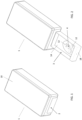
- Fig. 1 illustrates a remote control button actuation system 1 used to actuate a remote control constructed in accordance with the present disclosure.
- the actuation system 1 shown in Fig. 1 includes an outer housing 10 that is formed in two separate sections as will be described below.
- the outer housing 10 defines an open interior that receives a removable key fob drawer 3, which is shown in the retracted position in Fig. 1 and in the extended position in Fig. 2 .
- the key fob drawer 3 is sized to receive a key fob 4 that includes a series of individual buttons 12 that can be separately depressed to send wireless command signals to a vehicle.
- buttons 12 can be used to lock the car doors, unlock the car doors, start the engine, open the trunk, send a panic signal or perform other functions depending upon the configuration of the key fob 4.
- a key fob 4 is shown in Fig. 2 , it should be understood that various other configurations of the key fob 4 are contemplated as being within the scope of the present disclosure.
- the key fob 4 could be any type of remote that includes one or more buttons 12 that can be depressed to send a command signal to the vehicle when the remote is within the communication range of the vehicle.
- the communication range of the vehicle is typically all locations within the vehicle and a very close proximity to the vehicle.
- the key fob 4 is shown positioned on a floor 14 of the drawer 3. It is contemplated that the floor 14 could include one or more sticky pads that allow the key fob 4 to be securely held in the position as shown in Fig. 2 .
- the key fob drawer 3 includes a series of side walls 16 and a front wall 18. The front wall 18 can receive a removal cover 2 that forms part of an isolation enclosure as will be described.
- a three axis button actuator operable to move a plunger in the x, y and z axes such that the movable plunger can be accurately positioned above any one of the multiple buttons 12 on the key fob 4 when the key fob 4 is positioned within the key fob drawer.
- the actuator system includes a controller that is operable to control the position of the plunger and the movement in the z direction.
- One example embodiment of the three axis button actuator is shown and described in U.S. Patent 9,576,41 4 .
- Fig. 2 illustrates the key fob drawer 3 is in the extended position.
- the user can take a photo of the key fob 4 located within the drawer 3 utilizing a smartphone that is running application software.
- the application software on the smartphone processes the image to define the x and y positions of the center of each button 12 relative to the key fob drawer 3.
- the location of each button is determined based upon reference points of the drawer that are present in the photograph.
- the photograph of the key fob 4 within the drawer is taken with the drawer in the extended position. It is contemplated that the reference point in the drawer 3 could be reflective areas or markings on the floor 14 or the side walls 16 that allows the position of the key fob 4 to be accurately identified.
- this information is used to create location identification information which is sent from the application software on the smartphone to the controller located within the actuation system 1.
- the drawer 3 is retracted.
- the drawer 3 retracts to a known and physically defined location. Since the location of the key fob 4 is known relative to the floor 14 of the drawer 3 and the location of the drawer is also known, the controller can then operate the three-axis button actuator to position the plunger above any of the selected buttons 12 on the key fob 4.
- the depth of the button press which is the z button parameter, is determined using one or both of the following methods: 1) depressing the plunger while monitoring motor current and stopping at a predetermined amount of motor current and/or 2) monitoring for RF transmissions from the key fob indicating a button has been depressed.
- the housing is designed to create part of a Faraday cage for blocking all RF signals into or out of the housing.
- the removable drawer cover 2 shown in Fig. 1 is also formed from a metallic material to define a portion of the Faraday cage when the key fob drawer 3 is in the retracted position shown in Fig. 1 .
- An antenna is placed inside the Faraday cage for capturing RF transmissions of the key fob by the control system, which can then be relayed out of the housing.
- the remote control button actuation system 1 is designed such that the remote control button actuation system can be located in a secure location, such as a home or office 30.
- the entire remote control actuator system 1 can be securely located at the vehicle owner's home or business rather than being placed within the vehicle itself. In this manner, the key fob 4 can be completely separate from the vehicle to enhance security.
- the remote control actuator system 1 includes the three-axis button pressing system 32 that can be programed to press any one of multiple buttons 12 on the key fob 4.
- the three-axis button pressing system 32 is illustrated, it is contemplated that such system 32 could be replaced with a much simpler actuating system, such as if the system is used with a key fob having only one or two buttons. In either event, the system 32 is designed to activate/press a selected button on the key fob.
- the button pressing robot 32 can be actuated to move a plunger to cause the key fob 4 to generate the RF remote command signal that would otherwise be used to perform certain functions with respect to the vehicle.
- the wireless signals 34 generated by the key fob 4 are received within the control system 36.
- the control system 36 includes an RF transceiver, a decoder, a transmitter and a control unit for controlling activation of the systems within the remote control actuator system.
- the control system 36 decodes the wireless transmission and converts the RF transmission into a digital data message utilizing the decoder and controller. In this manner, the control system is able to convert an RF transmission into a digital message for further transmission.
- the digital message generated by the control system 36 can be transmitted away from the remote control button actuation system 1 utilizing multiple different types of communication.
- a wireless router 38 can be used to communicate to a remote server platform 40 utilizing a WiFi communication protocol.
- a wireless antenna 42 can be utilized to communicate to a receiver 44, which in turn is in communication with the remote server platform 40.
- the remote control actuator system can communicate utilizing long-range connectivity to the internet via cellular or Wi-Fi or can utilize Bluetooth or other wireless communication techniques to communicate to the remote server platform 40 through the receiver 44.
- the system of the present disclosure includes a proxy remote 46 that can be carried by the vehicle owner.
- the proxy remote 46 is a remote that is separate and distinct from the key fob remote 4 that is typically used with the vehicle.
- the proxy remote 46 can be positioned within or near the vicinity of the vehicle and is designed to interact with various systems in the vehicle when the proxy remote is within the communication range of the vehicle.
- the vehicle can include an RFID reader and/or low frequency passive entry/start.
- the proxy remote 46 is able to communicate with the vehicle ignition RFID reader 48 and the keyless entry system 50. Further, the proxy remote 46 is able to communicate with a telematics gateway 52 and with a wireless receiver/repeater 54.
- the proxy remote 46 is designed with the capability of decoding RF transmissions received from the vehicle and to encode RF transmissions that are transmitted to the vehicle. In this manner, the proxy remote 46 acts as a communication interface between a mobile device 22 of the user and the systems of the vehicle.
- the mobile device 22 shown in Fig. 4 can be any type of user interface that allows a vehicle owner to enter desired commands relative to the vehicle. It is contemplated that the mobile device 22 will be a smartphone although other mobile devices are able to be used in accordance with the present disclosure. Many different types of visual interfaces can be displayed on the mobile device 22 that could replicate typical key fob button commands, such as locking/unlocking doors, opening a trunk. Through the use of the mobile device 22, the vehicle owner would be able to control operation of the vehicle.
- a vehicle owner wishes to carry out some commands related to operation of the vehicle, such as unlocking doors, opening the trunk, or starting the vehicle
- the user engages a user interface 24 displayed on the screen of the mobile device 22.
- the mobile device 22 relays this desired command to the remote server platform 40 shown in Fig. 4 .
- the remote server platform 40 relays the desired command to the control system 36 of the remote control button actuation system 1.
- a controller of the control system 36 would then issue control commands to the three-axis button pressing system 32 to press the corresponding button on the key fob 4, resulting in the generation of an RF remote command signal.
- the RF remote command signal generated by the key fob 4 is received by the control system 36 and converted into digital form and stored in memory.
- the digital form of the RF remote command message is then transmitted away from the button actuation system 1, either utilizing the wireless router 38 or the antenna 42, to the remote server platform 40.
- the digital version of the button command is relayed either to the telematics gateway 52, to the mobile device 22 or directly to the proxy remote 46.
- the telematics gateway 52 is in communication with the proxy remote 46 such that the digital message from the controller of the remote control actuator system 1 is received by the proxy remote 46.
- the digital message from the controller corresponds to the RF remote command signal generated by the key fob 4 for the vehicle.
- the proxy remote 46 is designed to convert the digital message to an RF vehicle command signal which can then be transmitted by the proxy remote 46 and received by the ignition RFID reader 48 or the keyless entry system 50 of the vehicle.
- the RF vehicle command signal transmitted by the proxy remote 46 corresponds to the RF remote command signal generated by the key fob 4 such that the proxy remote 46 acts like the key fob 4.
- a command received from a user at the mobile device 22, such as unlock the doors ultimately results in the generation of an RF vehicle command signal by the proxy remote 46 to control the desired operation of various vehicle systems, such as the ignition, vehicle locks or trunk within the vehicle.
- the key fob 4 remains securely located at a home or office of the vehicle owner and is not present within the vehicle or located within communication range of the vehicle.
- the proxy remote 46 is able to generate the RF commands only upon receipt of digital messages from the remote control button actuation system 1. Thus, the proxy remote 46 can only function in combination with the key fob 4. Such enhanced security is believed to be a desirable feature and component of the system of the present disclosure.
- buttons commands messages can be preloaded into the memory on either the remote server platform 40 or directly onto the proxy remote 46.
- the controller of the control system 36 can actuate the door unlock button on the key fob 4 multiple times and create a digital message for the RF remote command signal generated during each button actuation.
- the digital messages could then be stored in the remote server platform 40 or stored directly on memory included within the proxy remote 46.
- the pre-stored command messages would then be accessed immediately after the interface screen on the mobile device 22 is depressed.
- the proxy remote 46 would be configured to enable the proxy remote 46 to interact with a vehicle ignition immobilizer or passive entry system by receiving RF commands from the vehicle.
- the RF commands from the vehicle would be decoded within the proxy remote 46, transmitted to the remote control button actuation system 1 and finally retransmitted via RF to the key fob 4.
- the key fob 4 would then respond with an RF response, which would be decoded within the remote control button actuation system 1 and transmitted back to the proxy remote, which would then transmit the response via RF to the vehicle.
- Such configuration would allow the proxy remote 46 to communicate the required response to the vehicle even though the key fob 4 for the vehicle is located at a remote location.
- the encryption algorithm used by the vehicle ignition immobilizer and keyless entry system could be decoded by studying the RF commands and responses from the vehicle and key fob 4.
- a duplicate encryption system would be created in the remote server platform 40, a mobile device app or proxy remote 46 that was synchronized to the vehicle.
- a remote control button actuation system 1 could be requested to command a key fob button press every time the duplicate encryption system issues a command. This would ensure that if the vehicle owner decided to return the original key fob, it would be in synchronization with the vehicle.
- the remote server platform 40 or other processing locations can be used to reverse engineer the public and private keys of the encryption algorithm utilized by the vehicle and key fob 4.
- the transmissions can be analyzed in an attempt to determine the encryption algorithm. Once the encryption algorithm has been determined, direct communication with the key fob 4 will no longer be required since the RF signal generated by the key fob 4 can be replicated either at the remote server platform 40 or at the proxy remote 46.
- the rolling code RF signals can be used to control a variety of controlled RF devices, such as vehicles, garage door openers, and security systems.
- controlled RF devices such as vehicles, garage door openers, and security systems.
- the use of such systems would eliminate the need of a physical remote control device such that the devices could become part of an internet of things (IoT) business model.
- IoT internet of things
- the three-axis button press robot 32 is included as part of the remote control button actuation system 1.
- the three-axis button press robot 32 could be replaced with a much more simple design that includes an actuator that is movable along a single-axis.
- one or more plungers would be manually located above a button on the key fob 4. The manual location of the plungers would thus require the plungers to move only in the z direction since the plunger would be accurately positioned above the key fob button 12.
- the controller 36 shown in Fig. 4 would still control the actuation of the plunger causing the key fob 4 to generate the RF signal.
- Such an embodiment may drastically decrease the cost of the remote control actuator system 1 since the button pressing robot 32 would be drastically simplified and manually set up by the user.
Landscapes
- Physics & Mathematics (AREA)
- General Physics & Mathematics (AREA)
- Engineering & Computer Science (AREA)
- Computer Networks & Wireless Communication (AREA)
- Lock And Its Accessories (AREA)
Description
- The present application is based on and claims priority to
U.S. Provisional Patent Application Serial Number 62/788,225, filed January 4, 2019 - Electronic systems in automotive vehicles and other devices may utilize handheld remote controls with finger-pressable buttons. These devices can be utilized to remotely actuate vehicle or device functions by hand, where such functions may be difficult to access otherwise by a vehicle operator. The remote controls of these electronic systems generally permit secure remote actuation of unlocking, locking, power door and trunk opening, remote engine starting, activation of horns, lights and panic features as well as other types of vehicle or device functions when the remote is within a communication range of the vehicle and the remote.
- In recent years, the rapid and widespread growth in long-range wireless connectivity and sophisticated hand-held mobile devices with touch-type graphical user interfaces and short or long-range wireless connectivity has led to the proliferation of machine-to-machine connectivity solutions and "anywhere at any time" device interactivity. Consumers now expect all of their vehicles, homes and devices to be connected and able to be interacted with via their mobile technology from anywhere and at any time.
- An increasing number of new vehicles come equipped with built-in wireless connectivity that enables connectivity to these vehicles via mobile devices and web-enabled devices for remote function actuation. Vehicles from General Motors, for example, equipped with ONSTAR telematics connectivity can be remotely started or unlocked with a smartphone running a downloaded software application ("app"). This is a proprietary, designed-in solution available only to purchasers of these vehicles and requires the purchase of an ongoing subscription from ONSTAR for the cellular data connectivity to the vehicle to enable this function.
- It is generally known that vehicle electronics suppliers have been offering retrofitted systems to expand the remote control capabilities available to vehicle owners. Directed Electronics, for example, offers aftermarket systems that control more functions and provide longer-range of connectivity, including the addition of telematics communications for control from any location with a smartphone application One primary limitation of these systems includes the need for extensive custom engineering efforts to enable the electronics to interface to and work with the electronics of the vehicles. In addition, consumers may be required to employ a professional technician for all installation efforts due to the technical complexity of the different vehicle installations. Consequently, these installations are generally expensive for consumers to consider.
- More recently, suppliers of aftermarket vehicle electronics have introduced systems that consumers can self-install at low-cost and complexity. Delphi Automotive, for example, has recently introduced a system that can be plugged into a standardized on-board diagnostics (OBD-II) connector found on all light-duty vehicles since 1996. The vehicle owner can easily install the system and, after downloading a smartphone application, can have remote control of vehicle access functions from their smartphone or a web-enabled device. By leveraging features found standard in many vehicles, this system advantageously allows for the addition of a new radio-frequency (RF) transmitter to operate as a secure remote control using procedures built into the vehicle by its manufacturer. Other suppliers are attempting to reverse engineer data bus commands for each vehicle to permit long-range remote control of the functions of the vehicle by transmitting data bus commands onto the OBD-II connector from a consumer-installed device. The main limitations of the RF control technique are that many vehicles do not have any available method for adding a new transmitter by the owner. Additionally, many vehicles have such sophisticated secure RF designs that no method can be found practically to transmit the proper secure codes to a vehicle.
- The main limitation of a data bus control technique is the extensive effort to reverse-engineer data bus commands for each vehicle. Additionally, many vehicles cannot be controlled via this connector at some or all of the time, such as when an owner is away from their vehicle due and/or due to a lack of available data bus commands.
-
U.S. Patent Publication No. 2009/0108989 A1 describes a remote control actuation system using a controller and solenoid(s) to press one or two remote control actuation buttons of a vehicle remote control. The system would be placed in a location within the confines of the vehicle. The '989 application describes an actuation method specific to a single type of remote control with a specific button location layout. The '989 application does not describe a configurable, or adaptable, system for mounting or actuating more than 2 buttons. The '989 application also fails to accommodate the numerous and widely-varying remote control multi-button designs found on vehicle remote control fobs, for example. Vehicle remote controls can have from 2 to 8 buttons in any type of layout and orientation on up to 3 surface planes of the remote control, varieties of package sizes and designs without a mechanical key blade and ones with fixed or movable mechanical key blades. - The '989 application also fails to provide for the linkage of remote control actuation to a user's mobile devices, e.g., a mobile smartphone application. Furthermore, the '989 application fails to describe a technique for blocking the vehicle detection of the remote control within the vehicle by low-frequency techniques used in vehicle immobilization or push-button engine start features. It is generally understood that vehicles and their remote controls can include a low-frequency circuitry that enables secure detection of the presence of the remote control within the vehicle. As such, blocking the RF function of the remote control and detection of the presence of the remote control can be used to prevent or alleviate the vehicle from being a target of drive-away theft.
- Therefore, there is a need in the art for a remote control to control the functions of a vehicle and/or other device, specifically for a singular design for wireless connectivity enhancements of linkage to mobile devices which can be added to all existing vehicle or device remote control systems without special tools or training. A further need exists for a system that allows the remote or key fob for a vehicle or a remote actuator for another device to be retained at a remote location outside of the communication range of the vehicle or device for security of the device while allowing for operation of the vehicle or device utilizing a mobile device. Document
US 2016/0049033 discloses a vehicle key base station configures to comprise at least one controller in communication with a key fob and a nomadic device using one or more transceivers. - The invention provides a system and a method as set out in the accompanying claims.
- In the Figures, like reference numerals refer to like parts throughout the various views unless otherwise indicated. For reference numerals with letter character designations such as "102A" or "102B", the letter character designations may differentiate two like parts or elements present in the same Figure. Letter character designations for reference numerals may be omitted when it is intended that a reference numeral to encompass all parts having the same reference numeral in all Figures.
-
Fig. 1 is a top isometric view of an exemplary embodiment of the remote control button actuation system of the present disclosure; -
Fig. 2 is a top isometric view showing the key fob drawer extended from the drawer housing; -
Fig. 3 is a schematic illustration of the proxy remote in the vehicle and illustrating the communication with various components of the system; and -
Fig. 4 is a mechanization diagram showing exemplary components of an exemplary embodiment of the remote button actuation system. - Aspects, features and advantages of several exemplary embodiments of the remote button actuation system will become better understood with regard to the following description in connection with the accompanying drawing(s). It should be apparent to those skilled in the art that the described embodiments of the present description provided herein are illustrative only and not limiting, having been presented by way of example only. All features disclosed in this description may be replaced by alternative features serving the same or similar purpose, unless expressly stated otherwise. Therefore, numerous other embodiments of the modifications thereof are contemplated as falling within the scope of the present description as defined herein and equivalents thereto. Hence, use of absolute terms such as, for example, "will," "will not," "shall," "shall not," "must" and "must not" are not meant to limit the scope of the present description as the embodiments disclosed herein are merely exemplary.
- The word "exemplary" is used herein to mean "serving as an example, instance, or illustration." Any aspect described herein as "exemplary" is not necessarily to be construed as exclusive, preferred or advantageous over other aspects.
- In this description, the term "portable computing device" ("PCD") is used to describe any device operating on a limited capacity power supply, such as a battery. Although battery operated PCDs have been in use for decades, technological advances in rechargeable batteries coupled with the advent of third generation ("3G") wireless technology have enabled numerous PCDs with multiple capabilities. Therefore, a PCD may be a cellular telephone, a satellite telephone, a pager, a PDA, a smartphone, a navigation device, a smartbook or reader, a media player, a combination of the aforementioned devices, a laptop computer with a wireless connection, among others.
-
Fig. 1 illustrates a remote controlbutton actuation system 1 used to actuate a remote control constructed in accordance with the present disclosure. Theactuation system 1 shown inFig. 1 includes anouter housing 10 that is formed in two separate sections as will be described below. Theouter housing 10 defines an open interior that receives a removablekey fob drawer 3, which is shown in the retracted position inFig. 1 and in the extended position inFig. 2 . Thekey fob drawer 3 is sized to receive akey fob 4 that includes a series ofindividual buttons 12 that can be separately depressed to send wireless command signals to a vehicle. As an example, thebuttons 12 can be used to lock the car doors, unlock the car doors, start the engine, open the trunk, send a panic signal or perform other functions depending upon the configuration of thekey fob 4. Although one specific configuration of akey fob 4 is shown inFig. 2 , it should be understood that various other configurations of thekey fob 4 are contemplated as being within the scope of the present disclosure. In addition, thekey fob 4 could be any type of remote that includes one ormore buttons 12 that can be depressed to send a command signal to the vehicle when the remote is within the communication range of the vehicle. The communication range of the vehicle is typically all locations within the vehicle and a very close proximity to the vehicle. - The
key fob 4 is shown positioned on afloor 14 of thedrawer 3. It is contemplated that thefloor 14 could include one or more sticky pads that allow thekey fob 4 to be securely held in the position as shown inFig. 2 . Thekey fob drawer 3 includes a series of side walls 16 and afront wall 18. Thefront wall 18 can receive a removal cover 2 that forms part of an isolation enclosure as will be described. - Included within the open interior of the
housing 10 is a three axis button actuator operable to move a plunger in the x, y and z axes such that the movable plunger can be accurately positioned above any one of themultiple buttons 12 on thekey fob 4 when thekey fob 4 is positioned within the key fob drawer. The actuator system includes a controller that is operable to control the position of the plunger and the movement in the z direction. One example embodiment of the three axis button actuator is shown and described inU.S. Patent 9,576,41 4 -
Fig. 2 illustrates thekey fob drawer 3 is in the extended position. When thedrawer 3 is in the extended position, the user can take a photo of thekey fob 4 located within thedrawer 3 utilizing a smartphone that is running application software. The application software on the smartphone processes the image to define the x and y positions of the center of eachbutton 12 relative to thekey fob drawer 3. The location of each button is determined based upon reference points of the drawer that are present in the photograph. The photograph of thekey fob 4 within the drawer is taken with the drawer in the extended position. It is contemplated that the reference point in thedrawer 3 could be reflective areas or markings on thefloor 14 or the side walls 16 that allows the position of thekey fob 4 to be accurately identified. - Once the location of the
key fob 4 is identified within the drawer, this information is used to create location identification information which is sent from the application software on the smartphone to the controller located within theactuation system 1. - After the location of the key fob is identified utilizing the application software on the smartphone, the
drawer 3 is retracted. Thedrawer 3 retracts to a known and physically defined location. Since the location of thekey fob 4 is known relative to thefloor 14 of thedrawer 3 and the location of the drawer is also known, the controller can then operate the three-axis button actuator to position the plunger above any of the selectedbuttons 12 on thekey fob 4. - The depth of the button press, which is the z button parameter, is determined using one or both of the following methods: 1) depressing the plunger while monitoring motor current and stopping at a predetermined amount of motor current and/or 2) monitoring for RF transmissions from the key fob indicating a button has been depressed.
- The housing is designed to create part of a Faraday cage for blocking all RF signals into or out of the housing. The removable drawer cover 2 shown in
Fig. 1 is also formed from a metallic material to define a portion of the Faraday cage when thekey fob drawer 3 is in the retracted position shown inFig. 1 . An antenna is placed inside the Faraday cage for capturing RF transmissions of the key fob by the control system, which can then be relayed out of the housing. - Referring now to
Fig. 4 , the remote controlbutton actuation system 1 is designed such that the remote control button actuation system can be located in a secure location, such as a home oroffice 30. The entire remotecontrol actuator system 1 can be securely located at the vehicle owner's home or business rather than being placed within the vehicle itself. In this manner, thekey fob 4 can be completely separate from the vehicle to enhance security. As described previously, the remotecontrol actuator system 1 includes the three-axisbutton pressing system 32 that can be programed to press any one ofmultiple buttons 12 on thekey fob 4. Although the three-axisbutton pressing system 32 is illustrated, it is contemplated thatsuch system 32 could be replaced with a much simpler actuating system, such as if the system is used with a key fob having only one or two buttons. In either event, thesystem 32 is designed to activate/press a selected button on the key fob. - Once the
key fob 4 is positioned within the drawer and the drawer is closed, thebutton pressing robot 32 can be actuated to move a plunger to cause thekey fob 4 to generate the RF remote command signal that would otherwise be used to perform certain functions with respect to the vehicle. In the embodiment shown inFig. 4 , the wireless signals 34 generated by thekey fob 4 are received within thecontrol system 36. Thecontrol system 36 includes an RF transceiver, a decoder, a transmitter and a control unit for controlling activation of the systems within the remote control actuator system. - When the wireless RF signals are received from the
key fob 4, thecontrol system 36 decodes the wireless transmission and converts the RF transmission into a digital data message utilizing the decoder and controller. In this manner, the control system is able to convert an RF transmission into a digital message for further transmission. The digital message generated by thecontrol system 36 can be transmitted away from the remote controlbutton actuation system 1 utilizing multiple different types of communication. In the embodiment illustrated, awireless router 38 can be used to communicate to aremote server platform 40 utilizing a WiFi communication protocol. Alternatively, awireless antenna 42 can be utilized to communicate to areceiver 44, which in turn is in communication with theremote server platform 40. In this manner, the remote control actuator system can communicate utilizing long-range connectivity to the internet via cellular or Wi-Fi or can utilize Bluetooth or other wireless communication techniques to communicate to theremote server platform 40 through thereceiver 44. - Referring now to
Figs 3 and4 , the system of the present disclosure includes a proxy remote 46 that can be carried by the vehicle owner. The proxy remote 46 is a remote that is separate and distinct from thekey fob remote 4 that is typically used with the vehicle. The proxy remote 46 can be positioned within or near the vicinity of the vehicle and is designed to interact with various systems in the vehicle when the proxy remote is within the communication range of the vehicle. As an illustrative example, the vehicle can include an RFID reader and/or low frequency passive entry/start. As illustrated inFig. 4 , the proxy remote 46 is able to communicate with the vehicleignition RFID reader 48 and thekeyless entry system 50. Further, the proxy remote 46 is able to communicate with atelematics gateway 52 and with a wireless receiver/repeater 54. - The proxy remote 46 is designed with the capability of decoding RF transmissions received from the vehicle and to encode RF transmissions that are transmitted to the vehicle. In this manner, the proxy remote 46 acts as a communication interface between a
mobile device 22 of the user and the systems of the vehicle. - The
mobile device 22 shown inFig. 4 can be any type of user interface that allows a vehicle owner to enter desired commands relative to the vehicle. It is contemplated that themobile device 22 will be a smartphone although other mobile devices are able to be used in accordance with the present disclosure. Many different types of visual interfaces can be displayed on themobile device 22 that could replicate typical key fob button commands, such as locking/unlocking doors, opening a trunk. Through the use of themobile device 22, the vehicle owner would be able to control operation of the vehicle. - The operation of the system of the present disclosure will now be described with reference to the drawing figures. Initially, when a vehicle owner wishes to carry out some commands related to operation of the vehicle, such as unlocking doors, opening the trunk, or starting the vehicle, the user engages a
user interface 24 displayed on the screen of themobile device 22. Themobile device 22 relays this desired command to theremote server platform 40 shown inFig. 4 . Theremote server platform 40, in turn, relays the desired command to thecontrol system 36 of the remote controlbutton actuation system 1. A controller of thecontrol system 36 would then issue control commands to the three-axisbutton pressing system 32 to press the corresponding button on thekey fob 4, resulting in the generation of an RF remote command signal. The RF remote command signal generated by thekey fob 4 is received by thecontrol system 36 and converted into digital form and stored in memory. The digital form of the RF remote command message is then transmitted away from thebutton actuation system 1, either utilizing thewireless router 38 or theantenna 42, to theremote server platform 40. From theremote server platform 40, the digital version of the button command is relayed either to thetelematics gateway 52, to themobile device 22 or directly to the proxy remote 46. Thetelematics gateway 52 is in communication with the proxy remote 46 such that the digital message from the controller of the remotecontrol actuator system 1 is received by the proxy remote 46. As indicated, the digital message from the controller corresponds to the RF remote command signal generated by thekey fob 4 for the vehicle. - The proxy remote 46 is designed to convert the digital message to an RF vehicle command signal which can then be transmitted by the proxy remote 46 and received by the
ignition RFID reader 48 or thekeyless entry system 50 of the vehicle. The RF vehicle command signal transmitted by the proxy remote 46 corresponds to the RF remote command signal generated by thekey fob 4 such that the proxy remote 46 acts like thekey fob 4. In this manner, a command received from a user at themobile device 22, such as unlock the doors, ultimately results in the generation of an RF vehicle command signal by the proxy remote 46 to control the desired operation of various vehicle systems, such as the ignition, vehicle locks or trunk within the vehicle. In such an embodiment, thekey fob 4 remains securely located at a home or office of the vehicle owner and is not present within the vehicle or located within communication range of the vehicle. The proxy remote 46 is able to generate the RF commands only upon receipt of digital messages from the remote controlbutton actuation system 1. Thus, the proxy remote 46 can only function in combination with thekey fob 4. Such enhanced security is believed to be a desirable feature and component of the system of the present disclosure. - As described above, several transmissions of information must occur when a vehicle owner selects a function on the
mobile device 22. In a best case scenario, the messages are transmitted without any significant delays. However, in order to avoid transmission delays over the cellular and internet connections, several different button commands messages can be preloaded into the memory on either theremote server platform 40 or directly onto the proxy remote 46. As an example, the controller of thecontrol system 36 can actuate the door unlock button on thekey fob 4 multiple times and create a digital message for the RF remote command signal generated during each button actuation. The digital messages could then be stored in theremote server platform 40 or stored directly on memory included within the proxy remote 46. The pre-stored command messages would then be accessed immediately after the interface screen on themobile device 22 is depressed. - If the
mobile device 22 were in direct communication with the proxy remote 46, such as shown by thecommunication line 56, depression of a portion of the screen of themobile device 22 would immediately result in the proxy remote generating the RF vehicle command signals to the system within the vehicle. Once a pre-loaded command was utilized, the command would be removed from memory and a fresh pre-loaded command would be requested from the remotecontrol actuator system 1. In this manner, a stored queue of commands would be available either within theremote server platform 40 or the memory on the proxy remote 46. - In yet another alternate embodiment of the present disclosure, the proxy remote 46 would be configured to enable the proxy remote 46 to interact with a vehicle ignition immobilizer or passive entry system by receiving RF commands from the vehicle. The RF commands from the vehicle would be decoded within the proxy remote 46, transmitted to the remote control
button actuation system 1 and finally retransmitted via RF to thekey fob 4. Thekey fob 4 would then respond with an RF response, which would be decoded within the remote controlbutton actuation system 1 and transmitted back to the proxy remote, which would then transmit the response via RF to the vehicle. Such configuration would allow the proxy remote 46 to communicate the required response to the vehicle even though thekey fob 4 for the vehicle is located at a remote location. - In yet another alternate embodiment of the present disclosure, the encryption algorithm used by the vehicle ignition immobilizer and keyless entry system could be decoded by studying the RF commands and responses from the vehicle and
key fob 4. In such an embodiment, a duplicate encryption system would be created in theremote server platform 40, a mobile device app or proxy remote 46 that was synchronized to the vehicle. To prevent a loss of synchronization of the original key fob with a vehicle through non-use, a remote controlbutton actuation system 1 could be requested to command a key fob button press every time the duplicate encryption system issues a command. This would ensure that if the vehicle owner decided to return the original key fob, it would be in synchronization with the vehicle. - In accordance with another contemplated feature of the present disclosure, the
remote server platform 40 or other processing locations can be used to reverse engineer the public and private keys of the encryption algorithm utilized by the vehicle andkey fob 4. As an illustrative example, when thekey fob 4 and vehicle use an encrypted, rolling code RF signal from thekey fob 4, the transmissions can be analyzed in an attempt to determine the encryption algorithm. Once the encryption algorithm has been determined, direct communication with thekey fob 4 will no longer be required since the RF signal generated by thekey fob 4 can be replicated either at theremote server platform 40 or at the proxy remote 46. - In the embodiment described immediately above, the rolling code RF signals can be used to control a variety of controlled RF devices, such as vehicles, garage door openers, and security systems. The use of such systems would eliminate the need of a physical remote control device such that the devices could become part of an internet of things (IoT) business model.
- As previously described, the three-axis
button press robot 32 is included as part of the remote controlbutton actuation system 1. However, it is contemplated that the three-axisbutton press robot 32 could be replaced with a much more simple design that includes an actuator that is movable along a single-axis. In such an embodiment, one or more plungers would be manually located above a button on thekey fob 4. The manual location of the plungers would thus require the plungers to move only in the z direction since the plunger would be accurately positioned above thekey fob button 12. In such an embodiment, thecontroller 36 shown inFig. 4 would still control the actuation of the plunger causing thekey fob 4 to generate the RF signal. Such an embodiment may drastically decrease the cost of the remotecontrol actuator system 1 since thebutton pressing robot 32 would be drastically simplified and manually set up by the user.
Claims (12)
- A system (1) to actuate one or more functions associated with one or more buttons on a remote for a vehicle based on command signals generated by a mobile device, the system comprising:a housing (10) configured to securely receive the remote;the mobile device (22);a user interface included on the mobile device, wherein command signals are generated by the mobile device based on interaction with the user interface;a controller located within the housing (10) and configured to receive command signals from the mobile device;a button actuator in the housing (10) and operable by the controller based upon the received command signal from the mobile device, wherein the button actuator is operable to engage one of the buttons of the remote such that the remote generates an RF remote command signal, wherein the controller receives the RF remote command signal and converts the RF remote command signal into a digital message, and wherein the housing (10) and button actuator are locatable for use outside of a communication range of the vehicle;a transmitter operable by the controller to transmit the digital message to a remote server platform;a proxy remote (46) positionable within the communication range of the vehicle to receive the digital message, whereinthe housing (10) is located outside a communication range of the vehicle and separate from the proxy remote, and wherein the proxy remote (46) is separate from the mobile device (22), convert the digital message into a RF vehicle command signal and transmit the RF vehicle command signal to the vehicle.
- The system (1) of claim 1 wherein the button actuator is positioned within the housing and/or wherein the housing is located outside of the communication range of the vehicle.
- The system (1) of claim 1 wherein the remote is a key fob.
- The actuation system (1) of claim 1,wherein the controller is configured to convert the command signal into position commands; andwherein the button actuator is configured to receive the position commands from the controller and actuate one of the buttons of the remote such that the remote generates the RF remote command signal.
- The system (1) of claim 1 or claim 4 further comprising the remote server platform operable to receive the digital message from the controller and to relay the digital message to the proxy remote.
- The system (1) of claim 5 wherein the remote server platform is operable to receive the command signal from the mobile device.
- The system (1) of claim 5 or claim 6 further comprising a telematics gateway operable to communicate with the proxy remote and the remote server platform.
- The system (1) of claim 1 or claim 4 wherein the proxy remote is operable to receive an RF identification signal from the vehicle and to transmit a response RF identification signal to the vehicle.
- The system (1) of claim 1 or claim 4 further comprising a memory device on the remote server platform or within the proxy remote operable to store a plurality of digital messages from the controller.
- A method of initiating one or more functions of a vehicle that are each associated with one or more buttons on a remote for the vehicle utilizing a mobile device, the method comprising:positioning the remote in a housing (10) that is located outside of a communication range of the vehicle;generating and transmitting a command signal from the mobile device based upon interaction with a user interface on the mobile device;receiving the command signal from the mobile device with a controller located within the housing;utilizing the controller to operate a button actuator within the housing (1) to engage one of the buttons on the remote associated with the command signal such that the remote generates an RF remote command signal;utilizing the controller to convert the RF remote command signal into a digital message;operating a transmitter in the housing (10) to transmit the digital message from the housing to a remote server platform;receiving the digital message at a proxy remote positioned within the communication range of the vehicle, wherein the housing (10) is located outside a communication range of the vehicle and separate from the proxy remote, and wherein the proxy remote (46) is separate from the mobile device (22);converting the digital message into a RF vehicle command signal at the proxy remote; andtransmitting the RF vehicle command signal from the proxy remote to the vehicle.
- The method of claim 10 further comprising the step of receiving the digital message in the remote server platform and relaying the digital message from the remote server platform to the proxy remote.
- The method of claim 10 further comprising the steps of:receiving an RF identification signal from the vehicle at the proxy remote; andtransmitting a response RF identification signal to the vehicle from the proxy remote.
Applications Claiming Priority (1)
| Application Number | Priority Date | Filing Date | Title |
|---|---|---|---|
| US201962788225P | 2019-01-04 | 2019-01-04 |
Publications (2)
| Publication Number | Publication Date |
|---|---|
| EP3678103A1 EP3678103A1 (en) | 2020-07-08 |
| EP3678103B1 true EP3678103B1 (en) | 2024-08-28 |
Family
ID=69104322
Family Applications (1)
| Application Number | Title | Priority Date | Filing Date |
|---|---|---|---|
| EP20150100.4A Active EP3678103B1 (en) | 2019-01-04 | 2020-01-02 | Remote control button actuation system with proxy remote |
Country Status (3)
| Country | Link |
|---|---|
| US (1) | US10977930B2 (en) |
| EP (1) | EP3678103B1 (en) |
| CA (1) | CA3066531A1 (en) |
Families Citing this family (7)
| Publication number | Priority date | Publication date | Assignee | Title |
|---|---|---|---|---|
| US11340649B2 (en) * | 2019-02-07 | 2022-05-24 | Blue Eclipse, Llc | Two button remote control actuator |
| US12534045B2 (en) | 2019-12-28 | 2026-01-27 | Light Wave Technology Inc. | Vehicle control system |
| WO2023113331A1 (en) * | 2021-12-13 | 2023-06-22 | 주식회사 위드라이브 | Bluetooth-based universal smart key control device using rack-and-pinion gear and servo motor |
| CN115188110A (en) * | 2022-08-02 | 2022-10-14 | 广州中胜物联网络科技有限公司 | Device and method for starting vehicle by using original vehicle remote controller in vehicle |
| CN115291551A (en) * | 2022-08-25 | 2022-11-04 | 开工啦(沈阳)科技有限公司 | Remote control system |
| US12128853B2 (en) * | 2022-12-16 | 2024-10-29 | The Adt Security Corporation | Integration of car security and home security system |
| JP2024113848A (en) * | 2023-02-10 | 2024-08-23 | 株式会社東海理化電機製作所 | ENCLOSURE DEVICE, CONTROL DEVICE, COMPUTER PROGRAM, AND METHOD FOR DETECTING WIRELESS COMMUNICATION DEVICE IN ENCLOSURE DEVICE |
Family Cites Families (9)
| Publication number | Priority date | Publication date | Assignee | Title |
|---|---|---|---|---|
| EP1848616A4 (en) | 2005-02-11 | 2010-05-19 | Keyless Lifestyles Pty Ltd | A personal access arrangement for a vehicle |
| US9199825B2 (en) * | 2009-10-06 | 2015-12-01 | Leonard Rudy Dueckman | Method and an apparatus for controlling a machine using motion based signals and inputs |
| US9576414B2 (en) | 2013-12-24 | 2017-02-21 | Tieman Vehicle Technologies LLC | Remote control button actuation module, system, and method |
| US9409297B2 (en) * | 2013-12-24 | 2016-08-09 | Tieman Vehicle Technologies LLC | Remote control button actuation module, system, and method |
| US9754431B2 (en) * | 2014-08-18 | 2017-09-05 | Livio, Inc. | Method and system for a key fob base station enabling remote car access using a nomadic device |
| US9483886B2 (en) * | 2014-10-01 | 2016-11-01 | Continental Intelligent Transportation Systems, LLC | Method and system for remote access control |
| US9710983B2 (en) * | 2015-01-29 | 2017-07-18 | GM Global Technology Operations LLC | Method and system for authenticating vehicle equipped with passive keyless system |
| US10960849B2 (en) * | 2018-08-14 | 2021-03-30 | Blue Eclipse, Llc | Remote control button actuator with removable tray |
| US10793108B2 (en) * | 2018-11-09 | 2020-10-06 | Ford Global Technologies, Llc | Bluetooth-enabled key fob |
-
2019
- 2019-12-31 US US16/731,380 patent/US10977930B2/en active Active - Reinstated
-
2020
- 2020-01-02 EP EP20150100.4A patent/EP3678103B1/en active Active
- 2020-01-02 CA CA3066531A patent/CA3066531A1/en active Pending
Also Published As
| Publication number | Publication date |
|---|---|
| CA3066531A1 (en) | 2020-07-04 |
| US20200219383A1 (en) | 2020-07-09 |
| EP3678103A1 (en) | 2020-07-08 |
| US10977930B2 (en) | 2021-04-13 |
Similar Documents
| Publication | Publication Date | Title |
|---|---|---|
| US10977930B2 (en) | Remote control button actuation system with proxy remote | |
| US10960849B2 (en) | Remote control button actuator with removable tray | |
| US11340649B2 (en) | Two button remote control actuator | |
| US8053922B2 (en) | Closing system for motor vehicles | |
| EP2048626B1 (en) | Apparatus for medium-range vehicle communications and control | |
| CN106558128B (en) | System and method for enhancing the range of a key fob | |
| EP1970264B2 (en) | Remote control method and system, vehicle with remote controllable function, and control server | |
| US20220180679A1 (en) | Vehicle control system | |
| KR102190894B1 (en) | Car management system | |
| US11285917B1 (en) | Vehicle control system | |
| US8581696B2 (en) | Universal garage door opener and appliance control system | |
| US20150061828A1 (en) | Intermediary Access Device for Communication With a Vehicle | |
| JP2016079600A (en) | Vehicle verification system | |
| KR102045033B1 (en) | Control device and method for unlocking a car with integrated NFC control | |
| US12534045B2 (en) | Vehicle control system | |
| JP2019078040A (en) | Key unit and control system | |
| WO2018145008A1 (en) | Selective transmission of commands associated with a single transceiver channel | |
| CN112622816A (en) | Networked vehicle control system and method thereof | |
| CN111163977A (en) | Access systems and access verification methods | |
| JP2022114671A (en) | Enclosure device and remote control system | |
| JP7808876B2 (en) | Systems and programs | |
| EP4489998A1 (en) | Multiuser authenticating system and method for keyless entry and starting a vehicle | |
| JP2018104958A (en) | Vehicle communication device | |
| JP2022114672A (en) | Housing device and remote control system | |
| JP2021123986A (en) | Door opening and closing system |
Legal Events
| Date | Code | Title | Description |
|---|---|---|---|
| PUAI | Public reference made under article 153(3) epc to a published international application that has entered the european phase |
Free format text: ORIGINAL CODE: 0009012 |
|
| STAA | Information on the status of an ep patent application or granted ep patent |
Free format text: STATUS: THE APPLICATION HAS BEEN PUBLISHED |
|
| AK | Designated contracting states |
Kind code of ref document: A1 Designated state(s): AL AT BE BG CH CY CZ DE DK EE ES FI FR GB GR HR HU IE IS IT LI LT LU LV MC MK MT NL NO PL PT RO RS SE SI SK SM TR |
|
| AX | Request for extension of the european patent |
Extension state: BA ME |
|
| STAA | Information on the status of an ep patent application or granted ep patent |
Free format text: STATUS: REQUEST FOR EXAMINATION WAS MADE |
|
| 17P | Request for examination filed |
Effective date: 20201231 |
|
| RBV | Designated contracting states (corrected) |
Designated state(s): AL AT BE BG CH CY CZ DE DK EE ES FI FR GB GR HR HU IE IS IT LI LT LU LV MC MK MT NL NO PL PT RO RS SE SI SK SM TR |
|
| STAA | Information on the status of an ep patent application or granted ep patent |
Free format text: STATUS: EXAMINATION IS IN PROGRESS |
|
| 17Q | First examination report despatched |
Effective date: 20211021 |
|
| GRAP | Despatch of communication of intention to grant a patent |
Free format text: ORIGINAL CODE: EPIDOSNIGR1 |
|
| STAA | Information on the status of an ep patent application or granted ep patent |
Free format text: STATUS: GRANT OF PATENT IS INTENDED |
|
| INTG | Intention to grant announced |
Effective date: 20231025 |
|
| RIN1 | Information on inventor provided before grant (corrected) |
Inventor name: TIEMAN, CRAIG ARNOLD |
|
| GRAS | Grant fee paid |
Free format text: ORIGINAL CODE: EPIDOSNIGR3 |
|
| GRAA | (expected) grant |
Free format text: ORIGINAL CODE: 0009210 |
|
| STAA | Information on the status of an ep patent application or granted ep patent |
Free format text: STATUS: THE PATENT HAS BEEN GRANTED |
|
| AK | Designated contracting states |
Kind code of ref document: B1 Designated state(s): AL AT BE BG CH CY CZ DE DK EE ES FI FR GB GR HR HU IE IS IT LI LT LU LV MC MK MT NL NO PL PT RO RS SE SI SK SM TR |
|
| REG | Reference to a national code |
Ref country code: CH Ref legal event code: EP |
|
| REG | Reference to a national code |
Ref country code: DE Ref legal event code: R096 Ref document number: 602020036485 Country of ref document: DE |
|
| REG | Reference to a national code |
Ref country code: IE Ref legal event code: FG4D |
|
| REG | Reference to a national code |
Ref country code: LT Ref legal event code: MG9D |
|
| PG25 | Lapsed in a contracting state [announced via postgrant information from national office to epo] |
Ref country code: NO Free format text: LAPSE BECAUSE OF FAILURE TO SUBMIT A TRANSLATION OF THE DESCRIPTION OR TO PAY THE FEE WITHIN THE PRESCRIBED TIME-LIMIT Effective date: 20241128 |
|
| REG | Reference to a national code |
Ref country code: AT Ref legal event code: MK05 Ref document number: 1718834 Country of ref document: AT Kind code of ref document: T Effective date: 20240828 |
|
| PG25 | Lapsed in a contracting state [announced via postgrant information from national office to epo] |
Ref country code: NL Free format text: LAPSE BECAUSE OF FAILURE TO SUBMIT A TRANSLATION OF THE DESCRIPTION OR TO PAY THE FEE WITHIN THE PRESCRIBED TIME-LIMIT Effective date: 20240828 Ref country code: PL Free format text: LAPSE BECAUSE OF FAILURE TO SUBMIT A TRANSLATION OF THE DESCRIPTION OR TO PAY THE FEE WITHIN THE PRESCRIBED TIME-LIMIT Effective date: 20240828 Ref country code: FI Free format text: LAPSE BECAUSE OF FAILURE TO SUBMIT A TRANSLATION OF THE DESCRIPTION OR TO PAY THE FEE WITHIN THE PRESCRIBED TIME-LIMIT Effective date: 20240828 Ref country code: GR Free format text: LAPSE BECAUSE OF FAILURE TO SUBMIT A TRANSLATION OF THE DESCRIPTION OR TO PAY THE FEE WITHIN THE PRESCRIBED TIME-LIMIT Effective date: 20241129 Ref country code: PT Free format text: LAPSE BECAUSE OF FAILURE TO SUBMIT A TRANSLATION OF THE DESCRIPTION OR TO PAY THE FEE WITHIN THE PRESCRIBED TIME-LIMIT Effective date: 20241230 |
|
| PG25 | Lapsed in a contracting state [announced via postgrant information from national office to epo] |
Ref country code: BG Free format text: LAPSE BECAUSE OF FAILURE TO SUBMIT A TRANSLATION OF THE DESCRIPTION OR TO PAY THE FEE WITHIN THE PRESCRIBED TIME-LIMIT Effective date: 20240828 |
|
| PG25 | Lapsed in a contracting state [announced via postgrant information from national office to epo] |
Ref country code: LV Free format text: LAPSE BECAUSE OF FAILURE TO SUBMIT A TRANSLATION OF THE DESCRIPTION OR TO PAY THE FEE WITHIN THE PRESCRIBED TIME-LIMIT Effective date: 20240828 |
|
| REG | Reference to a national code |
Ref country code: NL Ref legal event code: MP Effective date: 20240828 |
|
| PG25 | Lapsed in a contracting state [announced via postgrant information from national office to epo] |
Ref country code: IS Free format text: LAPSE BECAUSE OF FAILURE TO SUBMIT A TRANSLATION OF THE DESCRIPTION OR TO PAY THE FEE WITHIN THE PRESCRIBED TIME-LIMIT Effective date: 20241228 Ref country code: AT Free format text: LAPSE BECAUSE OF FAILURE TO SUBMIT A TRANSLATION OF THE DESCRIPTION OR TO PAY THE FEE WITHIN THE PRESCRIBED TIME-LIMIT Effective date: 20240828 |
|
| PG25 | Lapsed in a contracting state [announced via postgrant information from national office to epo] |
Ref country code: HR Free format text: LAPSE BECAUSE OF FAILURE TO SUBMIT A TRANSLATION OF THE DESCRIPTION OR TO PAY THE FEE WITHIN THE PRESCRIBED TIME-LIMIT Effective date: 20240828 |
|
| PG25 | Lapsed in a contracting state [announced via postgrant information from national office to epo] |
Ref country code: ES Free format text: LAPSE BECAUSE OF FAILURE TO SUBMIT A TRANSLATION OF THE DESCRIPTION OR TO PAY THE FEE WITHIN THE PRESCRIBED TIME-LIMIT Effective date: 20240828 Ref country code: RS Free format text: LAPSE BECAUSE OF FAILURE TO SUBMIT A TRANSLATION OF THE DESCRIPTION OR TO PAY THE FEE WITHIN THE PRESCRIBED TIME-LIMIT Effective date: 20241128 |
|
| PG25 | Lapsed in a contracting state [announced via postgrant information from national office to epo] |
Ref country code: RS Free format text: LAPSE BECAUSE OF FAILURE TO SUBMIT A TRANSLATION OF THE DESCRIPTION OR TO PAY THE FEE WITHIN THE PRESCRIBED TIME-LIMIT Effective date: 20241128 Ref country code: PT Free format text: LAPSE BECAUSE OF FAILURE TO SUBMIT A TRANSLATION OF THE DESCRIPTION OR TO PAY THE FEE WITHIN THE PRESCRIBED TIME-LIMIT Effective date: 20241230 Ref country code: PL Free format text: LAPSE BECAUSE OF FAILURE TO SUBMIT A TRANSLATION OF THE DESCRIPTION OR TO PAY THE FEE WITHIN THE PRESCRIBED TIME-LIMIT Effective date: 20240828 Ref country code: NO Free format text: LAPSE BECAUSE OF FAILURE TO SUBMIT A TRANSLATION OF THE DESCRIPTION OR TO PAY THE FEE WITHIN THE PRESCRIBED TIME-LIMIT Effective date: 20241128 Ref country code: NL Free format text: LAPSE BECAUSE OF FAILURE TO SUBMIT A TRANSLATION OF THE DESCRIPTION OR TO PAY THE FEE WITHIN THE PRESCRIBED TIME-LIMIT Effective date: 20240828 Ref country code: LV Free format text: LAPSE BECAUSE OF FAILURE TO SUBMIT A TRANSLATION OF THE DESCRIPTION OR TO PAY THE FEE WITHIN THE PRESCRIBED TIME-LIMIT Effective date: 20240828 Ref country code: IS Free format text: LAPSE BECAUSE OF FAILURE TO SUBMIT A TRANSLATION OF THE DESCRIPTION OR TO PAY THE FEE WITHIN THE PRESCRIBED TIME-LIMIT Effective date: 20241228 Ref country code: HR Free format text: LAPSE BECAUSE OF FAILURE TO SUBMIT A TRANSLATION OF THE DESCRIPTION OR TO PAY THE FEE WITHIN THE PRESCRIBED TIME-LIMIT Effective date: 20240828 Ref country code: GR Free format text: LAPSE BECAUSE OF FAILURE TO SUBMIT A TRANSLATION OF THE DESCRIPTION OR TO PAY THE FEE WITHIN THE PRESCRIBED TIME-LIMIT Effective date: 20241129 Ref country code: FI Free format text: LAPSE BECAUSE OF FAILURE TO SUBMIT A TRANSLATION OF THE DESCRIPTION OR TO PAY THE FEE WITHIN THE PRESCRIBED TIME-LIMIT Effective date: 20240828 Ref country code: ES Free format text: LAPSE BECAUSE OF FAILURE TO SUBMIT A TRANSLATION OF THE DESCRIPTION OR TO PAY THE FEE WITHIN THE PRESCRIBED TIME-LIMIT Effective date: 20240828 Ref country code: BG Free format text: LAPSE BECAUSE OF FAILURE TO SUBMIT A TRANSLATION OF THE DESCRIPTION OR TO PAY THE FEE WITHIN THE PRESCRIBED TIME-LIMIT Effective date: 20240828 Ref country code: AT Free format text: LAPSE BECAUSE OF FAILURE TO SUBMIT A TRANSLATION OF THE DESCRIPTION OR TO PAY THE FEE WITHIN THE PRESCRIBED TIME-LIMIT Effective date: 20240828 |
|
| PG25 | Lapsed in a contracting state [announced via postgrant information from national office to epo] |
Ref country code: SM Free format text: LAPSE BECAUSE OF FAILURE TO SUBMIT A TRANSLATION OF THE DESCRIPTION OR TO PAY THE FEE WITHIN THE PRESCRIBED TIME-LIMIT Effective date: 20240828 Ref country code: RO Free format text: LAPSE BECAUSE OF FAILURE TO SUBMIT A TRANSLATION OF THE DESCRIPTION OR TO PAY THE FEE WITHIN THE PRESCRIBED TIME-LIMIT Effective date: 20240828 Ref country code: DK Free format text: LAPSE BECAUSE OF FAILURE TO SUBMIT A TRANSLATION OF THE DESCRIPTION OR TO PAY THE FEE WITHIN THE PRESCRIBED TIME-LIMIT Effective date: 20240828 |
|
| PG25 | Lapsed in a contracting state [announced via postgrant information from national office to epo] |
Ref country code: EE Free format text: LAPSE BECAUSE OF FAILURE TO SUBMIT A TRANSLATION OF THE DESCRIPTION OR TO PAY THE FEE WITHIN THE PRESCRIBED TIME-LIMIT Effective date: 20240828 |
|
| PG25 | Lapsed in a contracting state [announced via postgrant information from national office to epo] |
Ref country code: CZ Free format text: LAPSE BECAUSE OF FAILURE TO SUBMIT A TRANSLATION OF THE DESCRIPTION OR TO PAY THE FEE WITHIN THE PRESCRIBED TIME-LIMIT Effective date: 20240828 |
|
| PG25 | Lapsed in a contracting state [announced via postgrant information from national office to epo] |
Ref country code: SK Free format text: LAPSE BECAUSE OF FAILURE TO SUBMIT A TRANSLATION OF THE DESCRIPTION OR TO PAY THE FEE WITHIN THE PRESCRIBED TIME-LIMIT Effective date: 20240828 Ref country code: IT Free format text: LAPSE BECAUSE OF FAILURE TO SUBMIT A TRANSLATION OF THE DESCRIPTION OR TO PAY THE FEE WITHIN THE PRESCRIBED TIME-LIMIT Effective date: 20240828 |
|
| REG | Reference to a national code |
Ref country code: DE Ref legal event code: R097 Ref document number: 602020036485 Country of ref document: DE |
|
| PLBE | No opposition filed within time limit |
Free format text: ORIGINAL CODE: 0009261 |
|
| STAA | Information on the status of an ep patent application or granted ep patent |
Free format text: STATUS: NO OPPOSITION FILED WITHIN TIME LIMIT |
|
| 26N | No opposition filed |
Effective date: 20250530 |
|
| REG | Reference to a national code |
Ref country code: CH Ref legal event code: PL |
|
| PG25 | Lapsed in a contracting state [announced via postgrant information from national office to epo] |
Ref country code: SE Free format text: LAPSE BECAUSE OF FAILURE TO SUBMIT A TRANSLATION OF THE DESCRIPTION OR TO PAY THE FEE WITHIN THE PRESCRIBED TIME-LIMIT Effective date: 20240828 |
|
| PG25 | Lapsed in a contracting state [announced via postgrant information from national office to epo] |
Ref country code: MC Free format text: LAPSE BECAUSE OF FAILURE TO SUBMIT A TRANSLATION OF THE DESCRIPTION OR TO PAY THE FEE WITHIN THE PRESCRIBED TIME-LIMIT Effective date: 20240828 Ref country code: LU Free format text: LAPSE BECAUSE OF NON-PAYMENT OF DUE FEES Effective date: 20250102 |
|
| PGFP | Annual fee paid to national office [announced via postgrant information from national office to epo] |
Ref country code: DE Payment date: 20250715 Year of fee payment: 6 |
|
| PG25 | Lapsed in a contracting state [announced via postgrant information from national office to epo] |
Ref country code: BE Free format text: LAPSE BECAUSE OF NON-PAYMENT OF DUE FEES Effective date: 20250131 |
|
| PGFP | Annual fee paid to national office [announced via postgrant information from national office to epo] |
Ref country code: GB Payment date: 20250715 Year of fee payment: 6 |
|
| PGFP | Annual fee paid to national office [announced via postgrant information from national office to epo] |
Ref country code: FR Payment date: 20250715 Year of fee payment: 6 |
|
| PG25 | Lapsed in a contracting state [announced via postgrant information from national office to epo] |
Ref country code: CH Free format text: LAPSE BECAUSE OF NON-PAYMENT OF DUE FEES Effective date: 20250131 |
|
| REG | Reference to a national code |
Ref country code: BE Ref legal event code: MM Effective date: 20250131 |
|
| PG25 | Lapsed in a contracting state [announced via postgrant information from national office to epo] |
Ref country code: IE Free format text: LAPSE BECAUSE OF NON-PAYMENT OF DUE FEES Effective date: 20250102 |