EP3677961A2 - Curved segmented active dimmable lens for a display system - Google Patents
Curved segmented active dimmable lens for a display system Download PDFInfo
- Publication number
- EP3677961A2 EP3677961A2 EP20150038.6A EP20150038A EP3677961A2 EP 3677961 A2 EP3677961 A2 EP 3677961A2 EP 20150038 A EP20150038 A EP 20150038A EP 3677961 A2 EP3677961 A2 EP 3677961A2
- Authority
- EP
- European Patent Office
- Prior art keywords
- ito
- display
- active
- layer
- segmented
- Prior art date
- Legal status (The legal status is an assumption and is not a legal conclusion. Google has not performed a legal analysis and makes no representation as to the accuracy of the status listed.)
- Pending
Links
Images


Classifications
-
- G—PHYSICS
- G02—OPTICS
- G02F—OPTICAL DEVICES OR ARRANGEMENTS FOR THE CONTROL OF LIGHT BY MODIFICATION OF THE OPTICAL PROPERTIES OF THE MEDIA OF THE ELEMENTS INVOLVED THEREIN; NON-LINEAR OPTICS; FREQUENCY-CHANGING OF LIGHT; OPTICAL LOGIC ELEMENTS; OPTICAL ANALOGUE/DIGITAL CONVERTERS
- G02F1/00—Devices or arrangements for the control of the intensity, colour, phase, polarisation or direction of light arriving from an independent light source, e.g. switching, gating or modulating; Non-linear optics
- G02F1/01—Devices or arrangements for the control of the intensity, colour, phase, polarisation or direction of light arriving from an independent light source, e.g. switching, gating or modulating; Non-linear optics for the control of the intensity, phase, polarisation or colour
- G02F1/13—Devices or arrangements for the control of the intensity, colour, phase, polarisation or direction of light arriving from an independent light source, e.g. switching, gating or modulating; Non-linear optics for the control of the intensity, phase, polarisation or colour based on liquid crystals, e.g. single liquid crystal display cells
- G02F1/137—Devices or arrangements for the control of the intensity, colour, phase, polarisation or direction of light arriving from an independent light source, e.g. switching, gating or modulating; Non-linear optics for the control of the intensity, phase, polarisation or colour based on liquid crystals, e.g. single liquid crystal display cells characterised by the electro-optical or magneto-optical effect, e.g. field-induced phase transition, orientation effect, guest-host interaction or dynamic scattering
-
- G—PHYSICS
- G02—OPTICS
- G02F—OPTICAL DEVICES OR ARRANGEMENTS FOR THE CONTROL OF LIGHT BY MODIFICATION OF THE OPTICAL PROPERTIES OF THE MEDIA OF THE ELEMENTS INVOLVED THEREIN; NON-LINEAR OPTICS; FREQUENCY-CHANGING OF LIGHT; OPTICAL LOGIC ELEMENTS; OPTICAL ANALOGUE/DIGITAL CONVERTERS
- G02F1/00—Devices or arrangements for the control of the intensity, colour, phase, polarisation or direction of light arriving from an independent light source, e.g. switching, gating or modulating; Non-linear optics
- G02F1/01—Devices or arrangements for the control of the intensity, colour, phase, polarisation or direction of light arriving from an independent light source, e.g. switching, gating or modulating; Non-linear optics for the control of the intensity, phase, polarisation or colour
- G02F1/13—Devices or arrangements for the control of the intensity, colour, phase, polarisation or direction of light arriving from an independent light source, e.g. switching, gating or modulating; Non-linear optics for the control of the intensity, phase, polarisation or colour based on liquid crystals, e.g. single liquid crystal display cells
- G02F1/133—Constructional arrangements; Operation of liquid crystal cells; Circuit arrangements
- G02F1/1333—Constructional arrangements; Manufacturing methods
- G02F1/1347—Arrangement of liquid crystal layers or cells in which the final condition of one light beam is achieved by the addition of the effects of two or more layers or cells
- G02F1/13475—Arrangement of liquid crystal layers or cells in which the final condition of one light beam is achieved by the addition of the effects of two or more layers or cells in which at least one liquid crystal cell or layer is doped with a pleochroic dye, e.g. GH-LC cell
-
- G—PHYSICS
- G02—OPTICS
- G02F—OPTICAL DEVICES OR ARRANGEMENTS FOR THE CONTROL OF LIGHT BY MODIFICATION OF THE OPTICAL PROPERTIES OF THE MEDIA OF THE ELEMENTS INVOLVED THEREIN; NON-LINEAR OPTICS; FREQUENCY-CHANGING OF LIGHT; OPTICAL LOGIC ELEMENTS; OPTICAL ANALOGUE/DIGITAL CONVERTERS
- G02F1/00—Devices or arrangements for the control of the intensity, colour, phase, polarisation or direction of light arriving from an independent light source, e.g. switching, gating or modulating; Non-linear optics
- G02F1/01—Devices or arrangements for the control of the intensity, colour, phase, polarisation or direction of light arriving from an independent light source, e.g. switching, gating or modulating; Non-linear optics for the control of the intensity, phase, polarisation or colour
- G02F1/13—Devices or arrangements for the control of the intensity, colour, phase, polarisation or direction of light arriving from an independent light source, e.g. switching, gating or modulating; Non-linear optics for the control of the intensity, phase, polarisation or colour based on liquid crystals, e.g. single liquid crystal display cells
- G02F1/137—Devices or arrangements for the control of the intensity, colour, phase, polarisation or direction of light arriving from an independent light source, e.g. switching, gating or modulating; Non-linear optics for the control of the intensity, phase, polarisation or colour based on liquid crystals, e.g. single liquid crystal display cells characterised by the electro-optical or magneto-optical effect, e.g. field-induced phase transition, orientation effect, guest-host interaction or dynamic scattering
- G02F1/13731—Devices or arrangements for the control of the intensity, colour, phase, polarisation or direction of light arriving from an independent light source, e.g. switching, gating or modulating; Non-linear optics for the control of the intensity, phase, polarisation or colour based on liquid crystals, e.g. single liquid crystal display cells characterised by the electro-optical or magneto-optical effect, e.g. field-induced phase transition, orientation effect, guest-host interaction or dynamic scattering based on a field-induced phase transition
- G02F1/13737—Devices or arrangements for the control of the intensity, colour, phase, polarisation or direction of light arriving from an independent light source, e.g. switching, gating or modulating; Non-linear optics for the control of the intensity, phase, polarisation or colour based on liquid crystals, e.g. single liquid crystal display cells characterised by the electro-optical or magneto-optical effect, e.g. field-induced phase transition, orientation effect, guest-host interaction or dynamic scattering based on a field-induced phase transition in liquid crystals doped with a pleochroic dye
-
- G—PHYSICS
- G02—OPTICS
- G02F—OPTICAL DEVICES OR ARRANGEMENTS FOR THE CONTROL OF LIGHT BY MODIFICATION OF THE OPTICAL PROPERTIES OF THE MEDIA OF THE ELEMENTS INVOLVED THEREIN; NON-LINEAR OPTICS; FREQUENCY-CHANGING OF LIGHT; OPTICAL LOGIC ELEMENTS; OPTICAL ANALOGUE/DIGITAL CONVERTERS
- G02F1/00—Devices or arrangements for the control of the intensity, colour, phase, polarisation or direction of light arriving from an independent light source, e.g. switching, gating or modulating; Non-linear optics
- G02F1/01—Devices or arrangements for the control of the intensity, colour, phase, polarisation or direction of light arriving from an independent light source, e.g. switching, gating or modulating; Non-linear optics for the control of the intensity, phase, polarisation or colour
- G02F1/13—Devices or arrangements for the control of the intensity, colour, phase, polarisation or direction of light arriving from an independent light source, e.g. switching, gating or modulating; Non-linear optics for the control of the intensity, phase, polarisation or colour based on liquid crystals, e.g. single liquid crystal display cells
- G02F1/133—Constructional arrangements; Operation of liquid crystal cells; Circuit arrangements
- G02F1/1333—Constructional arrangements; Manufacturing methods
- G02F1/1335—Structural association of cells with optical devices, e.g. polarisers or reflectors
- G02F1/133509—Filters, e.g. light shielding masks
- G02F1/133512—Light shielding layers, e.g. black matrix
-
- G—PHYSICS
- G02—OPTICS
- G02F—OPTICAL DEVICES OR ARRANGEMENTS FOR THE CONTROL OF LIGHT BY MODIFICATION OF THE OPTICAL PROPERTIES OF THE MEDIA OF THE ELEMENTS INVOLVED THEREIN; NON-LINEAR OPTICS; FREQUENCY-CHANGING OF LIGHT; OPTICAL LOGIC ELEMENTS; OPTICAL ANALOGUE/DIGITAL CONVERTERS
- G02F1/00—Devices or arrangements for the control of the intensity, colour, phase, polarisation or direction of light arriving from an independent light source, e.g. switching, gating or modulating; Non-linear optics
- G02F1/01—Devices or arrangements for the control of the intensity, colour, phase, polarisation or direction of light arriving from an independent light source, e.g. switching, gating or modulating; Non-linear optics for the control of the intensity, phase, polarisation or colour
- G02F1/13—Devices or arrangements for the control of the intensity, colour, phase, polarisation or direction of light arriving from an independent light source, e.g. switching, gating or modulating; Non-linear optics for the control of the intensity, phase, polarisation or colour based on liquid crystals, e.g. single liquid crystal display cells
- G02F1/133—Constructional arrangements; Operation of liquid crystal cells; Circuit arrangements
- G02F1/1333—Constructional arrangements; Manufacturing methods
- G02F1/1335—Structural association of cells with optical devices, e.g. polarisers or reflectors
- G02F1/133526—Lenses, e.g. microlenses or Fresnel lenses
-
- G—PHYSICS
- G02—OPTICS
- G02F—OPTICAL DEVICES OR ARRANGEMENTS FOR THE CONTROL OF LIGHT BY MODIFICATION OF THE OPTICAL PROPERTIES OF THE MEDIA OF THE ELEMENTS INVOLVED THEREIN; NON-LINEAR OPTICS; FREQUENCY-CHANGING OF LIGHT; OPTICAL LOGIC ELEMENTS; OPTICAL ANALOGUE/DIGITAL CONVERTERS
- G02F1/00—Devices or arrangements for the control of the intensity, colour, phase, polarisation or direction of light arriving from an independent light source, e.g. switching, gating or modulating; Non-linear optics
- G02F1/01—Devices or arrangements for the control of the intensity, colour, phase, polarisation or direction of light arriving from an independent light source, e.g. switching, gating or modulating; Non-linear optics for the control of the intensity, phase, polarisation or colour
- G02F1/13—Devices or arrangements for the control of the intensity, colour, phase, polarisation or direction of light arriving from an independent light source, e.g. switching, gating or modulating; Non-linear optics for the control of the intensity, phase, polarisation or colour based on liquid crystals, e.g. single liquid crystal display cells
- G02F1/133—Constructional arrangements; Operation of liquid crystal cells; Circuit arrangements
- G02F1/1333—Constructional arrangements; Manufacturing methods
- G02F1/1335—Structural association of cells with optical devices, e.g. polarisers or reflectors
- G02F1/133528—Polarisers
-
- G—PHYSICS
- G02—OPTICS
- G02F—OPTICAL DEVICES OR ARRANGEMENTS FOR THE CONTROL OF LIGHT BY MODIFICATION OF THE OPTICAL PROPERTIES OF THE MEDIA OF THE ELEMENTS INVOLVED THEREIN; NON-LINEAR OPTICS; FREQUENCY-CHANGING OF LIGHT; OPTICAL LOGIC ELEMENTS; OPTICAL ANALOGUE/DIGITAL CONVERTERS
- G02F1/00—Devices or arrangements for the control of the intensity, colour, phase, polarisation or direction of light arriving from an independent light source, e.g. switching, gating or modulating; Non-linear optics
- G02F1/01—Devices or arrangements for the control of the intensity, colour, phase, polarisation or direction of light arriving from an independent light source, e.g. switching, gating or modulating; Non-linear optics for the control of the intensity, phase, polarisation or colour
- G02F1/13—Devices or arrangements for the control of the intensity, colour, phase, polarisation or direction of light arriving from an independent light source, e.g. switching, gating or modulating; Non-linear optics for the control of the intensity, phase, polarisation or colour based on liquid crystals, e.g. single liquid crystal display cells
- G02F1/133—Constructional arrangements; Operation of liquid crystal cells; Circuit arrangements
- G02F1/1333—Constructional arrangements; Manufacturing methods
- G02F1/1339—Gaskets; Spacers; Sealing of cells
-
- G—PHYSICS
- G02—OPTICS
- G02F—OPTICAL DEVICES OR ARRANGEMENTS FOR THE CONTROL OF LIGHT BY MODIFICATION OF THE OPTICAL PROPERTIES OF THE MEDIA OF THE ELEMENTS INVOLVED THEREIN; NON-LINEAR OPTICS; FREQUENCY-CHANGING OF LIGHT; OPTICAL LOGIC ELEMENTS; OPTICAL ANALOGUE/DIGITAL CONVERTERS
- G02F1/00—Devices or arrangements for the control of the intensity, colour, phase, polarisation or direction of light arriving from an independent light source, e.g. switching, gating or modulating; Non-linear optics
- G02F1/01—Devices or arrangements for the control of the intensity, colour, phase, polarisation or direction of light arriving from an independent light source, e.g. switching, gating or modulating; Non-linear optics for the control of the intensity, phase, polarisation or colour
- G02F1/13—Devices or arrangements for the control of the intensity, colour, phase, polarisation or direction of light arriving from an independent light source, e.g. switching, gating or modulating; Non-linear optics for the control of the intensity, phase, polarisation or colour based on liquid crystals, e.g. single liquid crystal display cells
- G02F1/133—Constructional arrangements; Operation of liquid crystal cells; Circuit arrangements
- G02F1/1333—Constructional arrangements; Manufacturing methods
- G02F1/1343—Electrodes
- G02F1/13439—Electrodes characterised by their electrical, optical, physical properties; materials therefor; method of making
-
- G—PHYSICS
- G02—OPTICS
- G02F—OPTICAL DEVICES OR ARRANGEMENTS FOR THE CONTROL OF LIGHT BY MODIFICATION OF THE OPTICAL PROPERTIES OF THE MEDIA OF THE ELEMENTS INVOLVED THEREIN; NON-LINEAR OPTICS; FREQUENCY-CHANGING OF LIGHT; OPTICAL LOGIC ELEMENTS; OPTICAL ANALOGUE/DIGITAL CONVERTERS
- G02F1/00—Devices or arrangements for the control of the intensity, colour, phase, polarisation or direction of light arriving from an independent light source, e.g. switching, gating or modulating; Non-linear optics
- G02F1/01—Devices or arrangements for the control of the intensity, colour, phase, polarisation or direction of light arriving from an independent light source, e.g. switching, gating or modulating; Non-linear optics for the control of the intensity, phase, polarisation or colour
- G02F1/13—Devices or arrangements for the control of the intensity, colour, phase, polarisation or direction of light arriving from an independent light source, e.g. switching, gating or modulating; Non-linear optics for the control of the intensity, phase, polarisation or colour based on liquid crystals, e.g. single liquid crystal display cells
- G02F1/133—Constructional arrangements; Operation of liquid crystal cells; Circuit arrangements
- G02F1/1333—Constructional arrangements; Manufacturing methods
- G02F1/1335—Structural association of cells with optical devices, e.g. polarisers or reflectors
- G02F1/13356—Structural association of cells with optical devices, e.g. polarisers or reflectors characterised by the placement of the optical elements
- G02F1/133562—Structural association of cells with optical devices, e.g. polarisers or reflectors characterised by the placement of the optical elements on the viewer side
-
- G—PHYSICS
- G02—OPTICS
- G02F—OPTICAL DEVICES OR ARRANGEMENTS FOR THE CONTROL OF LIGHT BY MODIFICATION OF THE OPTICAL PROPERTIES OF THE MEDIA OF THE ELEMENTS INVOLVED THEREIN; NON-LINEAR OPTICS; FREQUENCY-CHANGING OF LIGHT; OPTICAL LOGIC ELEMENTS; OPTICAL ANALOGUE/DIGITAL CONVERTERS
- G02F1/00—Devices or arrangements for the control of the intensity, colour, phase, polarisation or direction of light arriving from an independent light source, e.g. switching, gating or modulating; Non-linear optics
- G02F1/01—Devices or arrangements for the control of the intensity, colour, phase, polarisation or direction of light arriving from an independent light source, e.g. switching, gating or modulating; Non-linear optics for the control of the intensity, phase, polarisation or colour
- G02F1/13—Devices or arrangements for the control of the intensity, colour, phase, polarisation or direction of light arriving from an independent light source, e.g. switching, gating or modulating; Non-linear optics for the control of the intensity, phase, polarisation or colour based on liquid crystals, e.g. single liquid crystal display cells
- G02F1/133—Constructional arrangements; Operation of liquid crystal cells; Circuit arrangements
- G02F1/1333—Constructional arrangements; Manufacturing methods
- G02F1/1339—Gaskets; Spacers; Sealing of cells
- G02F1/13398—Spacer materials; Spacer properties
-
- G—PHYSICS
- G02—OPTICS
- G02F—OPTICAL DEVICES OR ARRANGEMENTS FOR THE CONTROL OF LIGHT BY MODIFICATION OF THE OPTICAL PROPERTIES OF THE MEDIA OF THE ELEMENTS INVOLVED THEREIN; NON-LINEAR OPTICS; FREQUENCY-CHANGING OF LIGHT; OPTICAL LOGIC ELEMENTS; OPTICAL ANALOGUE/DIGITAL CONVERTERS
- G02F1/00—Devices or arrangements for the control of the intensity, colour, phase, polarisation or direction of light arriving from an independent light source, e.g. switching, gating or modulating; Non-linear optics
- G02F1/01—Devices or arrangements for the control of the intensity, colour, phase, polarisation or direction of light arriving from an independent light source, e.g. switching, gating or modulating; Non-linear optics for the control of the intensity, phase, polarisation or colour
- G02F1/13—Devices or arrangements for the control of the intensity, colour, phase, polarisation or direction of light arriving from an independent light source, e.g. switching, gating or modulating; Non-linear optics for the control of the intensity, phase, polarisation or colour based on liquid crystals, e.g. single liquid crystal display cells
- G02F1/137—Devices or arrangements for the control of the intensity, colour, phase, polarisation or direction of light arriving from an independent light source, e.g. switching, gating or modulating; Non-linear optics for the control of the intensity, phase, polarisation or colour based on liquid crystals, e.g. single liquid crystal display cells characterised by the electro-optical or magneto-optical effect, e.g. field-induced phase transition, orientation effect, guest-host interaction or dynamic scattering
- G02F1/13725—Devices or arrangements for the control of the intensity, colour, phase, polarisation or direction of light arriving from an independent light source, e.g. switching, gating or modulating; Non-linear optics for the control of the intensity, phase, polarisation or colour based on liquid crystals, e.g. single liquid crystal display cells characterised by the electro-optical or magneto-optical effect, e.g. field-induced phase transition, orientation effect, guest-host interaction or dynamic scattering based on guest-host interaction
-
- G—PHYSICS
- G02—OPTICS
- G02F—OPTICAL DEVICES OR ARRANGEMENTS FOR THE CONTROL OF LIGHT BY MODIFICATION OF THE OPTICAL PROPERTIES OF THE MEDIA OF THE ELEMENTS INVOLVED THEREIN; NON-LINEAR OPTICS; FREQUENCY-CHANGING OF LIGHT; OPTICAL LOGIC ELEMENTS; OPTICAL ANALOGUE/DIGITAL CONVERTERS
- G02F2201/00—Constructional arrangements not provided for in groups G02F1/00 - G02F7/00
- G02F2201/44—Arrangements combining different electro-active layers, e.g. electrochromic, liquid crystal or electroluminescent layers
-
- G—PHYSICS
- G02—OPTICS
- G02F—OPTICAL DEVICES OR ARRANGEMENTS FOR THE CONTROL OF LIGHT BY MODIFICATION OF THE OPTICAL PROPERTIES OF THE MEDIA OF THE ELEMENTS INVOLVED THEREIN; NON-LINEAR OPTICS; FREQUENCY-CHANGING OF LIGHT; OPTICAL LOGIC ELEMENTS; OPTICAL ANALOGUE/DIGITAL CONVERTERS
- G02F2202/00—Materials and properties
- G02F2202/04—Materials and properties dye
Definitions
- the active cell includes an indium-tin-oxide (ITO) common plane layer disposed on the second surface of the cover layer, one or more segmented ITO layers adjacent the ITO common plane layer, a dye-doped liquid crystal disposed between the ITO common plane layer and the one or more segmented ITO layers, and an encapsulation layer.
- the encapsulation layer cooperates with the ITO common plane layer to retain the dye-doped liquid crystal and one or more ITO segmented layers.
- a linear polarizer is disposed adjacent the encapsulation layer of the active cell and positioned between the encapsulation layer and the display.
- an active dimmable lens for use with a display in a display system includes a curved cover layer having a first surface and an opposing second surface.
- An active cell is disposed adjacent the second surface of the cover layer and operable to vary an optical signal transmitted from the display.
- the display system may convey graphical information to an occupant in a vehicle.
- the display system may utilize segmentation to convey graphical information. For example, the display system may divide a viewing window, which may also be referred to as a display area, into two or more regions. Each region may convey graphical information that is independent of the other region(s).
- the system may also include a flexible encapsulant layer disposed on the segmented indium-tin-oxide layer opposite the rigid lens.
- the system may further include a linear polarizer disposed on the flexible encapsulant layer, opposite the segmented indium tin-oxide layer.
- Figure 1 may reduce reflections behind the front, first surface of the lens by using either an active polarizer, such as E-Tint.
- an active polarizer such as E-Tint.
- the display area may appear black to a viewer's eye(s) and may be similar in appearance to a surrounding, black non-display area.
- a display system 20 for a platform 10 is disclosed.
- the display system 20 is not shown or described as part of a specific application. However, it should be appreciated that the display system 20, or embodiments thereof, may be utilized in many different applications for the platform 10, such as but not limited to a vehicular application, an entertainment application, an advertising display application, etc.,
- Control signals used to generate images on the displays 16a, 16b, 16c may be received from the control circuit 14.
- the display system 20 may also be mounted in other locations such as, for example, within a center stack below the console 12, between the front seats, or the like.
- the display system 20 may be operable in an inactive or "off state and in an active state, with one or more portions being illuminated.
- the control circuit 14 may receive commands and information, in the form of one or more input signals from various controls or components in the vehicle (not shown) and generate control signals that drive the one or more displays 16a, 16b, 16c of the display system 20.
- the cover layer 30 may be formed of one or more substances to create a substantially inelastic or rigid body or layer.
- the cover layer 30 may be constructed using glass that is formed under high temperature and pressure to create the curved lens surface.
- the cover layer 30 may be formed of a polycarbonate, acrylic or other optically clear substrate material using a molding process to form the curved lens arrangement.
- the optically clear substrate material of the cover layer 30 allows the optical signal DSP to pass through the second surface 38 and out of the first surface 36.
- a layer defined by a perimeter seal 44 for a liquid crystal cell 46 there may be a layer defined by a perimeter seal 44 for a liquid crystal cell 46.
- the perimeter seal 44 may seal in a guest host dye-doped liquid crystal system, which may comprise the liquid crystal cell 46.
- the type of guest host can be used as an active polarizer wherein the device polarizes light in one axis in the OFF state and allows light transmission in the ON state.
- the center of the display area 32 may not be covered by the fade pattern 60. As such, the center of the display area 32 may not be covered by any dots.
- dots may be printed (or otherwise applied) in a dense pattern at and near the edges of the display area 32, becoming gradually less dense until they are discontinued. In FIG. 4 , the dots of the fade pattern 60 are so large at the shown edges of the upper left corner that the display area 32 is completely opaque, with 0% light transmission. Within five millimeters (for example) of this position, the dots of the fade pattern 60 may get gradually smaller until they are discontinued. This may serve to soften the edges of the display area 32.
Landscapes
- Physics & Mathematics (AREA)
- Nonlinear Science (AREA)
- Chemical & Material Sciences (AREA)
- Crystallography & Structural Chemistry (AREA)
- General Physics & Mathematics (AREA)
- Optics & Photonics (AREA)
- Mathematical Physics (AREA)
- Liquid Crystal (AREA)
- Devices For Indicating Variable Information By Combining Individual Elements (AREA)
- Lenses (AREA)
Abstract
Description
- This application claims the benefit of
U.S. Provisional Patent Application No. 62/787,658, filed on January 2, 2019 - The present disclosure generally relates to visibility of electronic displays, and in particular to a curved segmented active dimmable lens for use with a display system.
- An automotive vehicle may include a display for conveying graphical information to one or more occupants in a vehicle. The display may be positioned in a dashboard of the vehicle. In the vehicle, the display may be part of an instrument cluster or an infotainment system. The display may include a flat screen.
- As electronic displays are utilized increasingly in automotive instrument clusters, original equipment manufacturers seek to hide the display opening and present a "seamless" appearance to the user such that the user cannot see any apertures or margin gaps around the display. The seamless lens hides the location of the display in an unlit condition, often referred to as a "dead front", "secret until lit", "black panel" or "dark panel" effect. In addition, the original equipment manufacturers seek to minimize an appearance of the rectangular display opening in an "on" condition caused by a back-luminance leakage of the display. Organic light emitting diode displays minimize the "on" condition leakage. However, the organic light emitting diode displays do not have sufficient luminance capability to utilize a neutral density film in front of the displays to generate a seamless dark panel effect.
- This section provides a general summary of the disclosure and is not a comprehensive disclosure of its full scope or all its features, aspects or objectives.
- According to one or more embodiments, a system may include a segmented indium-tin-oxide layer. The system may also include a rigid lens disposed over the segmented indium-tin-oxide layer. The rigid lens may be curved. The transmission rate of the curved lens element is variable in one or more segmented regions.
- In one or more embodiments, a display system includes a control circuit and a display in communication with the control circuit operable to generate an optical signal. An active dimmable lens cooperates with the display to receive the optical signal. The active dimmable lens includes a curved cover layer having a first surface and an opposing second surface and an active cell disposed adjacent the second surface of the cover layer operable to vary the optical signal transmitted from the display through the lens in response to a signal from the control circuit.
- The active cell includes an indium-tin-oxide (ITO) common plane layer disposed on the second surface of the cover layer, one or more segmented ITO layers adjacent the ITO common plane layer, a dye-doped liquid crystal disposed between the ITO common plane layer and the one or more segmented ITO layers, and an encapsulation layer. The encapsulation layer cooperates with the ITO common plane layer to retain the dye-doped liquid crystal and one or more ITO segmented layers. A linear polarizer is disposed adjacent the encapsulation layer of the active cell and positioned between the encapsulation layer and the display.
- The curved cover layer of the display is formed of a rigid optically clear substrate. The active cell includes a perimeter seal disposed between the one or more segmented ITO layers and the ITO common plane layer. The perimeter seal is configured to contain the dye-doped liquid crystal. The active cell includes ITO segmentations cooperating with the ITO common plane layer to define the one or more segmented ITO layers therebetween, wherein the ITO segmentations are non-conductive paths.
- The cover layer defines a display area. A fade pattern is disposed around a periphery of the display area. The fade pattern comprises a sinusoidal fade pattern. The sinusoidal fade pattern may include a half-sinusoidal fade pattern or rely on halftone fade technology.
- In one or more embodiments, a display system includes a control circuit and a display in communication with the control circuit operable to generate an optical signal. An active dimmable lens cooperates with the display to receive the optical signal. The active dimmable lens includes a curved cover layer having a first surface and an opposing second surface and defines a display area. A fade pattern is disposed around the periphery of the display area. An active cell is disposed adjacent the second surface of the cover layer operable to vary the optical signal transmitted from the display through the lens in response to a signal from the control circuit.
- The active cell includes an indium-tin-oxide (ITO) common plane layer disposed on the second surface of the cover layer, one or more segmented ITO layers adjacent the ITO common plane layer and ITO segmentations cooperating with the ITO common plane layer to define the one or more segmented ITO layers therebetween, wherein the ITO segmentations are non-conductive paths. A dye-doped liquid crystal is disposed between the ITO common plane layer and the one or more segmented ITO layers. A perimeter seal is disposed between the one or more segmented ITO layers and the ITO common plane layer. The perimeter seal is configured to contain the dye-doped liquid crystal.
- An encapsulation layer cooperates with the ITO common plane layer to retain the dye-doped liquid crystal and one or more ITO segmented layers. A linear polarizer is disposed adjacent the encapsulation layer of the active cell and positioned between the encapsulation layer and the display.
- In one or more embodiments, an active dimmable lens for use with a display in a display system includes a curved cover layer having a first surface and an opposing second surface. An active cell is disposed adjacent the second surface of the cover layer and operable to vary an optical signal transmitted from the display.
- The active cell includes an indium-tin-oxide (ITO) common plane layer disposed on the second surface of the cover layer, one or more segmented ITO layers adjacent the ITO common plane layer, a dye-doped liquid crystal disposed between the ITO common plane layer and the one or more segmented ITO layers, and an encapsulation layer. The encapsulation layer cooperates with the ITO common plane layer to retain the dye-doped liquid crystal and one or more ITO segmented layers. A linear polarizer is disposed adjacent the encapsulation layer of the active cell.
- The above features and advantages and other features and advantages of the present teachings are readily apparent from the following detailed description of the best modes for carrying out the teachings when taken in connection with the accompanying drawings.
- The accompanying drawings are provided for purposes of illustration and not by way of limitation.
-
FIGURE 1 is a perspective view of a display system positioned in a vehicular platform in accordance with one or more embodiments; -
FIGURE 2 is a schematic view of a display system positioned in a vehicular platform in accordance with one or more embodiments; -
FIGURE 3 is a perspective illustrative view of a display system positioned in a vehicular platform in accordance with one or more embodiments; -
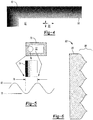
FIGURE 4 illustrates a schematic diagram of a fade pattern in a corner of a clear area of an opaque print in accordance with one or more embodiments; -
FIGURE 5 illustrates a schematic diagram of a half-sinusoidal transmission fade pattern in accordance with one or more embodiments; -
FIGURE 6 illustrates a schematic diagram of a sinusoidal spatial fade pattern in accordance with one or more embodiments; and - FIGURE 7 is an illustration of the spatial frequencies of the contrast sensitivity and contrast threshold functions in accordance with one or more embodiments.
- The present disclosure may have various modifications and alternative forms, and some representative embodiments are shown by way of example in the drawings and will be described in detail herein. Novel aspects of this disclosure are not limited to the forms illustrated in the above-enumerated drawings. Rather, the disclosure is to cover modifications, equivalents, and combinations falling within the scope of the disclosure as encompassed by the appended claims.
- Those having ordinary skill in the art will recognize that terms such as "above," "below," "upward," "downward," "top," "bottom," etc., are used descriptively for the figures, and do not represent limitations on the scope of the disclosure, as defined by the appended claims. Furthermore, the teachings may be described herein in terms of functional and/or logical block components and/or various processing steps. It should be realized that such block components may be comprised of any number of hardware, software, and/or firmware components operable to perform the specified functions.
- Referring to the Figures, wherein like numerals indicate corresponding parts throughout the several views, one or more embodiments relate to a display system. The display system may convey graphical information to an occupant in a vehicle. As opposed to a single, uniform presentation, the display system may utilize segmentation to convey graphical information. For example, the display system may divide a viewing window, which may also be referred to as a display area, into two or more regions. Each region may convey graphical information that is independent of the other region(s).
- One or more embodiments relate to a display system. The display system may convey graphical information to an occupant in a vehicle. As opposed to a single, uniform presentation, the display system may utilize segmentation to convey graphical information. For example, the display system may divide a viewing window, which may also be referred to as a display area, into two or more regions. Each region may convey graphical information that is independent of the other region(s). As part of the segmentation, the display system may include a segmented indium-tin-oxide layer. The system may also include a rigid lens disposed over the segmented indium-tin-oxide (ITO) layer. The rigid lens may be curved.
- The system may further include an indium-tin-oxide common plane layer disposed between the segmented indium-tin-oxide layer and the rigid lens. The system may additionally include dye-doped liquid crystal disposed between the segmented indium tin-oxide layer and the indium-tin-oxide common plane layer.
- The system may also include a perimeter seal disposed between the segmented indium-tin-oxide layer and the indium-tin-oxide common plane layer and may be configured to contain the dye-doped liquid crystal.
- The system may also include a flexible encapsulant layer disposed on the segmented indium-tin-oxide layer opposite the rigid lens. The system may further include a linear polarizer disposed on the flexible encapsulant layer, opposite the segmented indium tin-oxide layer.
- The rigid lens may define a display area. The system may further include a fade pattern disposed around a periphery of the display area. The fade pattern may include a two (2) dot pattern. The dots of the dot pattern type fade pattern may be on the order of thirty (30) microns.
- The fade pattern may be a sinusoidal fade pattern. In one example, the sinusoidal fade pattern may be a half-sinusoid. The sinusoidal fade pattern may rely on halftone fade technology. Halftone may refer to a technique that simulates continuous tone imagery using dots, varying in size, spacing, or both, thereby achieving a gradient-like effect. The sinusoidal fade pattern may include a combination of sine and cosine functions.
- One or more embodiments relate to a display system with a curved lens. The curved lens may include a variable transmission rate in one or more segmented regions of the curved lens. The curved lens may allow for a perfect black panel effect and curvature along one axis of the curved lens. The curvature may be a cross-car curvature, also known as a lateral curvature, or a side-to-side curvature.
- One or more embodiments relate to a display system that may include a curved, segmented, active dimmable lens with an active polarizer, such as E-Tint, to actively control transmission of a display area. The system may reduce reflections in the display area to mimic black reflection characteristics of a surrounding non-display area, so that a driver or other viewer may be unable to ascertain where the display system is located within a larger non-display area. This effect may be referred to as a hidden display effect. The hidden display effect may provide a seamless transition between the surrounding non-display area and the display system.
- The system may include a rigid, curved lens that is capable of being dimmed in selective regions. The interactive portion of the lens or display may be constructed of 3 polycarbonate or glass, for example. A portion of the interior side of the lens may be covered with ITO. A second surface may be operable to control the segmented dimming of the regions of the lens. The second surface may include electrically conductive and nonconductive paths. The second surface, or interactive layer, may conceal the conductive paths.
- One or more embodiments may include a display system that may permit reconfigurable content, such as graphical content, on a curved surface, while also hiding the display system when it is not needed.
- One or more embodiments may also have functionality to hide a location of a display system, when the display system is in an unlit condition. This effect may be referred to as dead front, secret until lit, black panel, or dark panel. In addition, one or more embodiments may minimize an appearance of a rectangular display area, when a display system is in the on condition. This may result from minimizing black luminance leakage the display system.
- One or more embodiments may provide a seamless design that uses the following principles. First, one or more embodiments may use a segmented active polarizer, such as E-Tint, to actively control the transmission of a display area. Second, one or more embodiments may reduce reflections in the display area to mimic a black reflection characteristic in a surrounding non-display area. Third, one or more embodiments may use a sinusoidal fade pattern to hide a display area. Fourth, one or more embodiments may use an anti-glare (AG) surface with good light scattering, low sparkle, and good image clarity characteristics. Fifth, one or more embodiments may use a rigid, curved lens as a first surface, which may also be a common plane of a liquid crystal active polarizer. ITO may be applied to an interior surface of the lens to make it electrically conductive. Sixth, one or more embodiments may use a flexible, optically clear substrate for a second layer of an active polarizer, which also has segmented ITO regions. Seventh, one or more embodiments may use a black printing layer on an interior surface of a rigid curved lens to hide the metallic tracking on a flexible substrate.
- In one or more embodiments, an interactive surface, or in other words, the surface that a user or occupant may touch and view, may include glass, polycarbonate, acrylic, or other such optically clear substrate. If glass, the interactive surface may be formed under high temperature and pressure to take a curved shape. Polymeric substrates may be molded or otherwise formed into rigid curved shapes. After shaping the glass to the desired shape, ITO may be applied to the interior surface, or in other words, the surface that is not touchable or directly viewable by the user or occupant.
- A second surface may control a dimming state for a display area. For example, the second surface may control dimming states over each segmented region on a lens. The second surface may include a flexible substrate, upon which ITO may be applied in one or more regions separated by nonconductive paths. Metallic tracking may be applied to connect the dimmable segmented regions to a connector, such as a flexible printed circuit (FPC) tail or the like.
- The interior surface of the interactive surface may cover and conceal the metallic tracking on the flexible substrate. The covering or concealing features may rely on a sinusoidal or other type of gradient pattern applied to hide the transition from the dimmable segmented regions to a surrounding non-display area.
- The flexible layer may be attached to a rigid layer such that the alignment of the dimmable segmented regions corresponds to undecorated windows on the lens. The layers may be secured with a perimeter bond. Prior to attachment of the two layers, micro spacers may be deposited between the layers to control the distance between the layers and prevent the flexible layer from collapsing and coming into direct contact with the rigid layer. A small opening may be left in a perimeter seal.
- Utilizing Liquid Crystal Injection (LCI), the lens assembly may be dipped into a vat of dye doped liquid crystal such that the opening in the perimeter seal is submerged in the liquid crystal material.
- Negative pressure may be applied, causing the liquid crystal material to fill a cell gap between the rigid layer, which may be a front layer, and the flexible segmented layer, which may be a rear layer. After the cell is filled, the opening in the perimeter seal may be closed to prevent the liquid crystal material from leaking out. At this point, this may result in a sub-assembly, which may be known as an Active Polarizer Cell.
- In the case of an active polarizer configuration, the display system may be further optimized by applying a linear polarizer to the back of the lens sub-assembly. The transmission axis of the linear polarizer and the transmission axis of the active polarizer (in the OFF state) may be ninety degrees (90°) from one another. The linear polarizer may be a static linear polarizer. The transmission axis of the linear polarizer may be the same as a display that is installed behind the linear polarizer.
- Through one or more methods, a display may be mounted behind the segmented regions, such as by utilizing perimeter bonding, Liquid Optically Clear Adhesive (LOCA) bonding, optically clear adhesive (OCA) lamination, air gap construction, or the like. In the case of air gap assemblies, optical performance may be further enhanced using one or more moth-eye films.
- Optical treatments, such as Anti-Glare (AG), Anti-Fingerprint (AF), Anti-Reflection (AR), or the like, may be applied to the front, interactive surface of the lens to further improve the optical performance of the system.
- As will be discussed below, an example is outlined in
Figure 1 . The example ofFigure 1 may reduce reflections behind the front, first surface of the lens by using either an active polarizer, such as E-Tint. By reducing reflections after the AG surface, the display area may appear black to a viewer's eye(s) and may be similar in appearance to a surrounding, black non-display area. - Referring now to
FIG. 1 , adisplay system 20 for aplatform 10 is disclosed. Thedisplay system 20 is not shown or described as part of a specific application. However, it should be appreciated that thedisplay system 20, or embodiments thereof, may be utilized in many different applications for theplatform 10, such as but not limited to a vehicular application, an entertainment application, an advertising display application, etc., - Exemplary vehicular applications of the
platform 10 include but are not limited to automobiles, airplanes, trains, boats, motorcycles, all-terrain vehicles (ATVs), utility type vehicles (UTVs), etc. For example, thedisplay system 20 may be incorporated into an instrument cluster, a center console display, a passenger entertainment display, or the like. Thedisplay system 20 may convey graphical information, vehicular applications, entertainment applications and the like to an occupant in theplatform 10. Exemplary entertainment applications include, but are not limited to, gaming systems, televisions, computer screens, etc. In some embodiments, theplatform 10 may be part of a stationary object which may include, but are not limited to, billboards, kiosks and/or marquees. - As shown in
FIG. 1 , an exemplary platform is avehicle 10 generally including a dashboard orconsole 12, an electronic control unit or control circuit (CC) 14 and a crosscockpit display console 16. Thecross-cockpit display console 16 generally includes one ormore displays display system 20. One or more of thedisplays display system 20 may be located directly in front of a driver or viewer as shown bydisplay 16a. However, as illustrated bydisplays more displays 16 of thedisplay system 20 may be located proximate the driver in other positions of thevehicle 10 such as in a central portion of theconsole 12. - The
cross-cockpit display console 16 may extend across a console area of thevehicle 10. As illustrated, thedisplay 16a may be an instrument cluster display or instrument panel console positioned for use by a driver. Thedisplay 16b may be a center console or an information display positioned on a central portion of theconsole 12 for use by the driver and a passenger. Thedisplay 16c may be an information display positioned for use by the passenger. - Other numbers of
displays displays display system 20 may utilize segmentation to convey graphical information. For example, thedisplay system 20 may divide a viewing window, which may also be referred to as a display area, into two or more regions. Each region may convey graphical information that is independent of the other region(s). In various embodiments, alldisplays display other displays - Control signals used to generate images on the
displays control circuit 14. Thedisplay system 20 may also be mounted in other locations such as, for example, within a center stack below theconsole 12, between the front seats, or the like. Thedisplay system 20 may be operable in an inactive or "off state and in an active state, with one or more portions being illuminated. Thecontrol circuit 14 may receive commands and information, in the form of one or more input signals from various controls or components in the vehicle (not shown) and generate control signals that drive the one ormore displays display system 20. - In various embodiments, the control signals may be operable to provide instrumentation (e.g. speed, tachometer, fuel, temperature, etc.) to at least one
display 16a of the one ormore displays displays displays - Referring now to
FIG. 2 , a schematic illustration of anexemplary display system 20 in accordance with one or more embodiments is disclosed. In some embodiments, thedisplay system 20 may be representative of thedisplays FIG. 1 . Thedisplay system 20 cooperates with thecontrol circuit 14, adisplay 22 and an activedimmable lens 24. The activedimmable lens 24 may be positioned before thedisplay 22. The activedimmable lens 24 and thedisplay 22 may be electrically connected to thecontrol circuit 14. - The components of the
display system 20, including, but not limited to, thedisplay 22 and activedimmable lens 24, may be coupled to thecontrol circuit 14 in a wired or wireless manner. The control circuit (CC) 14 may implement one or more display-drive circuits. Thecontrol circuit 14 may include one or more processors, each of which may be embodied as a separate processor, an application specific integrated circuit (ASIC), or a dedicated electronic control unit. - The
control circuit 14 may be any sort of electronic processor (implemented in hardware, software, or a combination of both). Thecontrol circuit 14 also includes tangible, non-transitory memory, e.g., read only memory in the form of optical, magnetic, and/or flash memory. For example, thecontrol circuit 14 may include application-suitable amounts of random-access memory, read-only memory, flash memory and other types of electrically-erasable programmable read-only memory, as well as accompanying hardware in the form of a high-speed clock or timer, analog-to-digital and digital-to-analog circuitry, and input/output circuitry and devices, as well as appropriate signal conditioning and buffer circuitry. - Computer-readable and executable instructions embodying the present method may be stored in memory and executed as set forth herein. The executable instructions may be a series of instructions employed to run applications on the control circuit 14 (either in the foreground or background).
- An optical signal (e.g., DSP) may be generated by the
display 22 and transmitted through the activedimmable lens 24. The optical signal DSP may be an optical signal that carries multiple visible images. The visible images may include words, numbers, pictures, graphical shapes, video and information related to the vehicular platform (e.g., radio, entertainment, climate control, etc.). - A display signal (e.g., D) may be generated by the
control circuit 14 and received by the display 2. The display signal D may carry information used by thedisplay 22 to modulate the optical signal DSP. Thecontrol circuit 14 may also generate a brightness signal (e.g., B) received by the activedimmable lens 24. The brightness signal B may convey control data (e.g., a voltage) used to control the dimming of the activedimmable lens 24. The brightness signal B may be implemented as multiple brightness signals B, one for each of the segments as will be defined in more detail below. - The control circuit is generally operational to generate the display information in the display signal D. The
control circuit 14 may also be operational to generate and present the brightness information in the brightness signal B. In various embodiments, aseparate control circuit 14 may be implemented for eachdisplay FIG. 1 . In some designs, asingle control circuit 14 may be operational to simultaneously control two ormore displays - The
display 22 may implement a display panel that generates the optical signal DSP. Thedisplay 22 may be a color display or a black-and-white display. Thedisplay 22 may be mounted adjacent (or adjoining) the activedimmable lens 24. Thedisplay 22 may be on an opposite side of the activedimmable lens 24 as the people. Thedisplay 22 is generally operational to change the images in the optical signal DSP in response to the display signal D. The changes generally include modulating the intensity and the color of the images. The modulated light may form the images in the optical signal DSP. In various embodiments, thedisplay 22 may be implemented as a liquid crystal display (LCD), a thin-film transistor (TFT) liquid crystal display, an active-matrix liquid crystal display or a passive liquid crystal display with a backlighting source. Other display technologies may be implemented to meet the design criteria of an application. - The active
dimmable lens 24 may implement a segmented type active dimmable lens. A segmented type activedimmable lens 24 may be operable to control the optical transmission characteristics through multiple segments (or areas) of the activedimmable lens 24. The transmission characteristics of each segment may be controlled separately. - By way of example, the active
dimmable lens 24 of thedisplays display 16a, another segment for thedisplay 16b and still another segment for thedisplay 16c. Therefore, the driver sitting on a shaded side of the vehicle may adjust thedisplay 16a to a preferred brightness level while the passenger sitting on a sunny side of the vehicle may adjust thedisplay 16c to a different brightness level. In various embodiments, the activedimmable lens 24 may rigid. In other embodiments, activedimmable lens 24 may be flexible to conform to contours of a console of the vehicle. -
FIGS. 2 and3 show an exemplary cross-section of thedisplay system 20 having a curved activedimmable lens 24 with multiple layers disposed proximate thedisplay 22. It is understood that the curvature, thickness, and the like of the activedimmable lens 24 are for purposes of illustration and are not drawn or described to scale. - One or more embodiments may include a
display system 20 that may permit reconfigurable content, such as graphical content, on a curved surface of thelens 24, while also hiding thedisplay system 20 when it is not needed. The curved activedimmable lens 24 may include a variable transmission rate in one or more segmented regions of thecurved lens 24. Thecurved lens 24 may allow for a perfect black panel effect and curvature along one axis of thecurved lens 24. The curvature may be a cross-car curvature, also known as a lateral curvature, or a side-to-side curvature. - One or more embodiments may also have functionality to hide a location of a
display system 20, when thedisplay system 20 is in an unlit condition. This effect may be referred to as dead front, secret until lit, black panel, or dark panel. In addition, one or more embodiments may minimize an appearance of a rectangular display area, when adisplay system 20 is in the on condition. This may result from minimizing black luminance leakage thedisplay system 20. - The curved active
dimmable lens 24 may include a cover layer orlens 30 defining a display area, generally referenced bynumeral 32. The curved activedimmable lens 24 may be capable of being dimmed in selective regions. In an exemplary embodiment, the activedimmable lens 24 may be curved along at least oneaxis 34. It is understood that the activedimmable lens 24 may be curved alongmultiple axes 34. It is further appreciated that, where curvatures of the activedimmable lens 24 occur aboutmultiple axes 34, that the multiple curvatures do not intersect to create a compound curvature. - The
cover layer 30 may be implemented as an optically transparent layer. Thecover layer 30 may provide mechanical support for the curved activedimmable lens 24. Afirst surface 36 of thecover layer 30 may face the passenger compartment of thevehicle 10 shown inFIG. 1 . Asecond surface 38 of thecover layer 30 may face thedisplay 22. Protection of the lower layers of the activedimmable lens 24 may be provided by thecover layer 30. - The
cover layer 30 may be formed of one or more substances to create a substantially inelastic or rigid body or layer. In one non-limiting example, thecover layer 30 may be constructed using glass that is formed under high temperature and pressure to create the curved lens surface. Alternatively, thecover layer 30 may be formed of a polycarbonate, acrylic or other optically clear substrate material using a molding process to form the curved lens arrangement. The optically clear substrate material of thecover layer 30 allows the optical signal DSP to pass through thesecond surface 38 and out of thefirst surface 36. - In one non-limiting embodiment, an anti-glare film (not shown) may be implemented as an anti-glare neutral density film. The anti-glare film may be applied to the
first surface 36 of thecover layer 30. The anti-glare film is generally operational to reduce glare caused external light incident on thedisplay system 20. Other optical treatments, such as anti-fingerprint (AF), anti-reflection (AR), or the like, may be applied to the front, interactive surface orfirst surface 36 of thecover layer 30 to further improve the optical performance of thedisplay system 20. - An
active cell 40 may be positioned proximate or disposed adjacent thesecond surface 38 of thecover layer 30 and disposed between thecover layer 30 and thedisplay 22. Active segmented liquid crystal technologies may be utilized together with a gradient transition pattern to foster a seamless appearance. As will be described in greater detail below, theactive cell 40 may include an active polarizer cell configuration or an electronic tint ("E-tint") cell configuration. - The
active cell 40 cooperates with thecover layer 30 to reduce reflections behind thefirst surface 36 of thecover layer 30 during operation, thereby creating an effect that the display opening area appears black to a viewer and similar in appearance to the surrounding black area. Theactive cell 40 of the curved activedimmable lens 24 cooperates with thedisplay 22 to receive the optical signal DSP from thedisplay 22 and vary a transmission of the optical signal DSP through theactive cell 40 in response to a brightness signal B from thecontrol circuit 14. - The
active cell 40 includes an indium-tin-oxide (ITO)common plane layer 42 applied to or cooperating with thesecond surface 38 of thecover layer 30. The ITOcommon plane layer 42 may be applied to at least a portion of the second or interior receivingsurface 38 of thelens 24. It is contemplated that the ITOcommon plane layer 42 is not viewable or touchable by a user of thedisplay system 20. - In one or more exemplary embodiments, a flexible substrate may be applied to the
second surface 38 of thecover layer 30 to receive the ITOcommon plane layer 42. Metallic tracking may be applied to the flexible substrate positioned proximate thesecond surface 38 of thecover layer 30. The ITOcommon plane layer 42 may include electrically conductive paths in one or more regions of the flexible substrate. Non-conductive paths separate the segmented one or more regions of the ITOcommon plane layer 42 and may be concealed on thesecond surface 38. - On the ITO
common plane layer 42, there may be a layer defined by aperimeter seal 44 for aliquid crystal cell 46. Theperimeter seal 44 may seal in a guest host dye-doped liquid crystal system, which may comprise theliquid crystal cell 46. In one non-limiting embodiment, the type of guest host can be used as an active polarizer wherein the device polarizes light in one axis in the OFF state and allows light transmission in the ON state. - The
liquid crystal cell 46 of theactive cell 40 may be based on a guest-host dichroic dye liquid crystal system where the guest dye acts as the polarizing element. The dye may either be orthogonal or parallel to the host liquid crystal molecules and therefore the off state may be the polarizing state or the unpolarized state. For a key-off dead-front application, the off state may be the polarizing state. An amount (density) of the dye added to the liquid crystal mixture generally affects the cell operation. As an example, if the dye density is selected for a perpendicular (e.g., dye molecules are perpendicular to the surface, unpolarized state) transmission of 70%, when the polarized state is activated the transmission may drop to about 2%. - The
liquid crystal cell 46 may be disposed between the ITOcommon plane layer 42 and one or more segmented ITO layers 48. Different segments of the one or more segmented ITO layers 48 may be separated from one another withITO segmentations 50. The one or more segmented ITO layers 48 andITO segmentations 50 may be disposed within theactive cell 40 and may be applied to and received by aflexible encapsulant layer 52 of theactive cell 40. - In one non-limiting embodiment, the segmented ITO layers 48 are regionally applied to portions of the
flexible encapsulant layer 52 in areas that correspond to areas where active control of transmission rate occurs. As shown inFIGS. 2 and3 , theflexible encapsulant layer 52 cooperates with thecover layer 30 and theperimeter seal 44 to define a cell gap receiving theliquid crystal cell 46 for theactive cell 40. It is contemplated that theliquid crystal cell 46 may be assembled in the cell gap under negative pressure or a vacuum through a liquid crystal injection (LCI) process. - Transmission of the optical signals DSP through the
active cell 40 may be variable in response to brightness signals applied to the one or more ITO segmented layers 48. The electrically conductive and non-conductive paths may connect the dimmable segments of theactive cell 40 to a connector, such as a flexible printed circuit (FPC) tail for communication with thecontrol circuit 14. Theactive cell 40, in response to thecontrol circuit 14, may control a dimming state for thedisplay area 32 of thecover layer 30. - Each ITO segmented
layer 48 may be individually controlled by a component of the brightness signal B. When a non-zero control voltage in the brightness signal B is applied by thecontrol circuit 14 across the one or moresegmented layers 48, a portion of theactive cell 40 may establish a polarization of the optical signal DSP from thedisplay 22. A degree of the polarization may be controlled by an amplitude of the control voltage. Use of the one or moresegmented layers 48 with theliquid crystal cell 46 allows the transmission of the display opening area to be adjusted dynamically to the level required for display visibility while maintaining a seamless appearance to a viewer of thedisplay system 20. - While the one or more ITO segmented layers 48 are in the power-off condition, the polarization of light passing between the one or more ITO segmented layers 48 may be oriented relative to the polarization of a
linear polarizer 54 to provide a maximum attenuation of the light (e.g., the optical signal DSP). While a maximum the control voltage is applied to one or more of the ITO segmented layers 48, the resulting polarization may align with the polarization of thelinear polarizer 54 and so provide minimum attenuation of the light. - In an exemplary embodiment, the optical performance of the
lens system 24 can be further improved by addition of alinear polarizer 54. Thelinear polarizer 54 may be static. The transmission axis of thelinear polarizer 54 is aligned with the transmission axis of thedisplay 22. When theactive cell 40 is in an OFF state, theactive cell 40 and thelinear polarizer 54 are orthogonal to each other, wherein theactive cell 40 and thelinear polarizer 54 cross polarize the light or optical signal DSP generated by thedisplay 22. In this OFF condition, near zero light or portion of the optical signal DSP passes through thecover layer 30 of thelens 24. - When the
control circuit 14 places theactive cell 40 in an ON condition to adjust the brightness B of thedisplay 22, a voltage is applied to the ITO segment layers 48 in theactive cell 40. The dye-dopedliquid crystal cell 46 realigns within theactive cell 40 in response to the applied voltage to allow the light or optical signal DSP to pass through theactive cell 40 with only a minor transmission loss and then through thecover layer 30 of thelens 24. - It is contemplated that the
display 22 andlens 24 of thedisplay system 20 may be connected to each other by a bonding process, including, but not limited to, perimeter bonding, Liquid Optically Clear Adhesive (LOCA) bonding, Optically Clear Adhesive (OCA) lamination, air gap construction or the like. In the case of air gap bonding construction or assembly, optical performance may be enhanced using moth-eye films or other optical enhancement techniques. - Referring now to
FIGS. 2-6 , thedisplay area 32 of thecover layer 30 of the activedimmable lens 24 may include an opaque print including anexemplary fade pattern 60 disposed around a periphery of thedisplay area 32. The opaque print may include an opaque area surrounding the clear area. The opaque print may include afade pattern 60 between the opaque area and the clear area. The fade pattern may serve as a transition between the opaque area and the clear area. The fade pattern may include a dot pattern. For example, the dot pattern may include columns of dots. A column may include a first dot proximal to the opaque area and distal the clear area and a second dot proximal to the clear area and distal to the opaque area. The first dot may have a dimension that is greater than the second dot. In a column, the size of the dots may taper the size of the dots from a greatest size being proximal to the opaque area to a smallest size being proximal to the clear area. The fade pattern, such as for the dot pattern, may include a sinusoidal pattern or half-sinusoidal pattern. - In one exemplary embodiment, the
fade pattern 60 may be applied to thesecond surface 38 of thecover layer 30. The fade pattern may incorporate a two (2) dot pattern, though it is appreciated different quantity and configuration of dot patterns may be adopted to accomplish the objectives of the disclosure. The dots of the dot pattern type fadepattern 60 may be on the order of around 30 microns. Thefade pattern 60 may be applied to at least partially hide or obscure the display opening from view of an occupant of the vehicle. - The fade pattern may be a sinusoidal fade pattern. In one example, the sinusoidal fade pattern may be a half-sinusoid. The sinusoidal fade pattern may rely on halftone fade technology. Halftone may refer to a technique that simulates continuous tone imagery using dots, varying in size, spacing, or both, thereby achieving a gradient-like effect. The sinusoidal fade pattern may include a combination of sine and cosine functions.
-
FIG. 4 illustrates a schematic diagram of afade pattern 60 in a corner of theclear area 62 of thedisplay area 32 of thecover layer 30 in accordance with one or more embodiments. Thefade pattern 60 as shown inFIG. 4 is applied to an upper left corner of thedisplay area 32 of thecover layer 30 and cooperates to define aclear area 62 of thedisplay area 32. It is understood that that fade pattern may be applied in one or more locations of thedisplay area 32 of thecover layer 30 to accomplish the objectives of the disclosure. - In addition to the film and display configurations, another aspect that may be added to the solution is the
fade pattern 60 surrounding theclear area 62 and intruding into the active area of thedisplay area 32. Thefade pattern 60 may implement dot pattern comprising rows and columns of smaller andsmaller dots 64. Thefade pattern 60 may be only an example of a sinusoidal fade pattern. Other dot patterns that are not periodic and are more random in nature may be implemented to meet the design criteria of an application. Asize 66 of theclear area 62 may be smaller than that of thedisplay 22. - The center of the
display area 32 may not be covered by thefade pattern 60. As such, the center of thedisplay area 32 may not be covered by any dots. As part of thefade pattern 60, dots may be printed (or otherwise applied) in a dense pattern at and near the edges of thedisplay area 32, becoming gradually less dense until they are discontinued. InFIG. 4 , the dots of thefade pattern 60 are so large at the shown edges of the upper left corner that thedisplay area 32 is completely opaque, with 0% light transmission. Within five millimeters (for example) of this position, the dots of thefade pattern 60 may get gradually smaller until they are discontinued. This may serve to soften the edges of thedisplay area 32. -
FIG. 5 illustrates a schematic diagram of a half-sinusoidaltransmission fade pattern 70 in accordance with one or more embodiments. Half-sinusoidal fade patterns may be good fade patterns in nature. The fade pattern may be half-sinusoidal, meaning that the light transmission is at a minimum at the outside edge of the pattern and at a maximum at the inside edge of the pattern, with a variation approximating that of a sine wave. For example, light transmission T may vary with respect to distance from the edge x. If the entire width of the pattern is treated as x going from O degrees to 90 degrees, then light transmission over the width of the pattern may be expressed by T = sin(x), such that at the outside edge x = 0 and T = 0, whereas at the inside edge x = 90 degrees and T = 1. - The half-sinusoidal
transmission fade pattern 70 may be implemented as a halftone fade pattern or other types of fade technologies since a sinusoidal pattern has the lowest number of Fourier spatial frequencies. The lowest sinusoidal spatial frequency may work well due to a contrast sensitivity characteristics per the Contrast Sensitivity Function (CSF) of the human eye. The half-sinusoidaltransmission fade pattern 70 may be developed by several means. For example, a combination of cosine and sine functions may be used to produce the half-sinusoidal fade pattern 70 along the edge of adisplay opening 72. Due to fabrication feature size capabilities, a pitch of the pattern may be made small, for example, around thirty (30) micrometers, and the half-sinusoidaltransmission fade pattern 70 may appear as acontinuous fade pattern 74 to the eye and the periodic structure would not be seen. Spatial frequencies below about six (6) cycles per degree generally have a lower contrast sensitivity (e.g., are harder to see). - In various embodiments, a
width 76 of thecontinuous fade pattern 74 may extend over a range of approximately three (3) millimeters (mm) to approximately seven (7) mm (e.g., five (5) mm). Thecontinuous fade pattern 74 may range from a zero percent (e.g., no)transmission level 78 to a specifiedtransmission level 80. -
FIG. 6 illustrates a schematic diagram of a sinusoidalspatial fade pattern 82 in accordance with one or more embodiments. The sinusoidalspatial fade pattern 82 may include a spatially varyingopaque area 84 adjoining a solidopaque area 86. The varyingopaque area 84 may be spatially modulated in a series of sinusoidal patterns as shown. As shown in FIG. 7, a contrast sensitivity function of the eye shows that spatial frequencies below approximately 6 cycles per degree generally have a lower contrast sensitivity (e.g., harder to see). Note that the solidopaque area 86 of thesinusoidal fade pattern 82 may also help to hide the display border in the on condition. - The above examples have focused on a rectangular display, but the same principles may be applied to other shapes of displays, including circular displays, square displays, and so on. Other modifications to the above embodiments are permitted, as the preceding are merely non-limiting examples.
- The detailed description and the drawings or figures are supportive and descriptive of the disclosure, but the scope of the disclosure is defined solely by the claims. While some of the best modes and other embodiments for carrying out the claimed teachings have been described in detail, various alternative designs and embodiments exist for practicing the disclosure defined in the appended claims.
Claims (15)
- A display system comprising:a control circuit;a display in communication with the control circuit operable to generate an optical signal; andan active dimmable lens cooperating with the display to receive the optical signal from the display and vary a transmission of the optical signal through the lens, wherein the active dimmable lens includes:a curved cover layer having a first surface and an opposing second surface,an active cell disposed adjacent the second surface of the cover layer operable to vary the optical signal transmitted from the display through the active cell in response to a signal from the control circuit, wherein the active cell includes:an indium-tin-oxide (ITO) common plane layer disposed on the second surface of the cover layer,one or more segmented ITO layers adjacent the ITO common plane layer,a dye-doped liquid crystal disposed between the ITO common plane layer and the one or more segmented ITO layers, andan encapsulation layer, wherein the encapsulation layer cooperates with the ITO common plane layer to retain the dye-doped liquid crystal and one or more ITO segmented layers, anda linear polarizer operable to polarize the optical signal disposed adjacent the encapsulation layer of the active cell and positioned between the encapsulation layer and the display.
- The display system of claim 1 wherein the cover layer is formed of a rigid optically clear substrate.
- The display system of claim 1 wherein the active cell of the active dimmable lens further comprises a perimeter seal disposed between the one or more segmented ITO layers and the ITO common plane layer, wherein the perimeter seal is configured to contain the dye-doped liquid crystal.
- The display system of claim 1 wherein the active cell of the active dimmable lens further comprises ITO segmentations cooperating with the ITO common plane layer to define the one or more segmented ITO layers therebetween, wherein the ITO segmentations are non-conductive paths.
- The display system of claim 1 wherein the cover layer of the active dimmable lens is configured to define a display area.
- The display system of claim 5 wherein a fade pattern is disposed around a periphery of the display area.
- The display system of claim 6 wherein the fade pattern comprises a sinusoidal fade pattern.
- The display system of claim 7 wherein the sinusoidal fade pattern comprises a half-sinusoidal fade pattern.
- The display system of claim 7 wherein the sinusoidal fade pattern relies on halftone fade technology.
- An active dimmable lens for use with a display in a display system, the active dimmable lens comprising:a curved cover layer having a first surface and an opposing second surface;an active cell disposed adjacent the second surface of the cover layer operable to vary an optical signal transmitted from the display, wherein the active cell includes:an indium-tin-oxide (ITO) common plane layer disposed on the second surface of the cover layer,one or more segmented ITO layers adjacent the ITO common plane layer,a dye-doped liquid crystal disposed between the ITO common plane layer and the one or more segmented ITO layers, andan encapsulation layer, wherein the encapsulation layer cooperates with the ITO common plane layer to retain the dye-doped liquid crystal and one or more ITO segmented layers; anda linear polarizer operable to polarize the optical signal from the display disposed adjacent the encapsulation layer of the active cell.
- The active dimmable lens of claim 10 wherein the active cell further comprises a perimeter seal disposed between the one or more segmented ITO layers and the ITO common plane layer, wherein the perimeter seal is configured to contain the dye-doped liquid crystal.
- The active dimmable lens of claim 10 wherein the active cell further comprises ITO segmentations cooperating with the ITO common plane layer to define the one or more segmented ITO layers therebetween, wherein the ITO segmentations are non-conductive paths.
- The active dimmable lens of claim 10 wherein the cover layer of the active dimmable lens is configured to define a display area.
- The active dimmable lens of claim 13 wherein a fade pattern is disposed around a periphery of the display area.
- The active dimmable lens of claim 14 wherein the fade pattern comprises a sinusoidal fade pattern.
Priority Applications (1)
| Application Number | Priority Date | Filing Date | Title |
|---|---|---|---|
| EP26156306.8A EP4715461A2 (en) | 2019-01-02 | 2020-01-02 | Curved segmented active dimmable lens for a display system |
Applications Claiming Priority (1)
| Application Number | Priority Date | Filing Date | Title |
|---|---|---|---|
| US201962787658P | 2019-01-02 | 2019-01-02 |
Related Child Applications (1)
| Application Number | Title | Priority Date | Filing Date |
|---|---|---|---|
| EP26156306.8A Division EP4715461A2 (en) | 2019-01-02 | 2020-01-02 | Curved segmented active dimmable lens for a display system |
Publications (2)
| Publication Number | Publication Date |
|---|---|
| EP3677961A2 true EP3677961A2 (en) | 2020-07-08 |
| EP3677961A3 EP3677961A3 (en) | 2020-07-22 |
Family
ID=69104285
Family Applications (2)
| Application Number | Title | Priority Date | Filing Date |
|---|---|---|---|
| EP26156306.8A Pending EP4715461A2 (en) | 2019-01-02 | 2020-01-02 | Curved segmented active dimmable lens for a display system |
| EP20150038.6A Pending EP3677961A3 (en) | 2019-01-02 | 2020-01-02 | Curved segmented active dimmable lens for a display system |
Family Applications Before (1)
| Application Number | Title | Priority Date | Filing Date |
|---|---|---|---|
| EP26156306.8A Pending EP4715461A2 (en) | 2019-01-02 | 2020-01-02 | Curved segmented active dimmable lens for a display system |
Country Status (3)
| Country | Link |
|---|---|
| US (1) | US10871693B2 (en) |
| EP (2) | EP4715461A2 (en) |
| CN (1) | CN111399297B (en) |
Families Citing this family (1)
| Publication number | Priority date | Publication date | Assignee | Title |
|---|---|---|---|---|
| US12566330B2 (en) * | 2021-10-22 | 2026-03-03 | Samsung Display Co., Ltd. | Head mount display device |
Family Cites Families (12)
| Publication number | Priority date | Publication date | Assignee | Title |
|---|---|---|---|---|
| US5220442A (en) | 1991-09-06 | 1993-06-15 | Xerox Corporation | Method of making color liquid crystal display with dead front appearance |
| JPH0673739U (en) * | 1993-03-30 | 1994-10-18 | 株式会社ニコン | Prescription electrochromic spectacle lens |
| JP2000122085A (en) * | 1998-10-12 | 2000-04-28 | Kawaguchiko Seimitsu Co Ltd | Liquid crystal photochromic glass and electronic instrument and device using the same |
| US7145611B2 (en) * | 2000-12-22 | 2006-12-05 | Honeywell International, Inc. | Seamless tiled display system |
| US7893890B2 (en) * | 2007-03-05 | 2011-02-22 | The Boeing Company | Electrically dimmable combiner optics for head-up display |
| CN102388333A (en) * | 2009-04-09 | 2012-03-21 | Lg电子株式会社 | Display apparatus |
| EP2983040B1 (en) * | 2014-07-25 | 2019-05-22 | LG Display Co., Ltd. | Transparent display based on a guest-host cholesteric liquid crystal device |
| CN105487157A (en) * | 2014-08-13 | 2016-04-13 | 南京晶多新材料科技有限公司 | Construction and application of electric control light modulation film serving as scattering polaroid |
| WO2017134865A1 (en) * | 2016-02-05 | 2017-08-10 | 日立マクセル株式会社 | Head-up display device |
| CN105572930A (en) * | 2016-03-23 | 2016-05-11 | 京东方科技集团股份有限公司 | Display module and display system |
| JP2017181888A (en) * | 2016-03-31 | 2017-10-05 | 大日本印刷株式会社 | Light control film and laminate of light control film |
| JP2018088010A (en) * | 2018-02-28 | 2018-06-07 | 大日本印刷株式会社 | Dimmer |
-
2020
- 2020-01-02 US US16/732,870 patent/US10871693B2/en active Active
- 2020-01-02 CN CN202010002444.4A patent/CN111399297B/en active Active
- 2020-01-02 EP EP26156306.8A patent/EP4715461A2/en active Pending
- 2020-01-02 EP EP20150038.6A patent/EP3677961A3/en active Pending
Also Published As
| Publication number | Publication date |
|---|---|
| CN111399297B (en) | 2024-04-02 |
| EP3677961A3 (en) | 2020-07-22 |
| EP4715461A2 (en) | 2026-03-25 |
| CN111399297A (en) | 2020-07-10 |
| US10871693B2 (en) | 2020-12-22 |
| US20200209657A1 (en) | 2020-07-02 |
Similar Documents
| Publication | Publication Date | Title |
|---|---|---|
| EP3699678B1 (en) | System for adjusting light intensity in a display system | |
| US20190331959A1 (en) | Segmented active dimmable lens with radiant transition pattern | |
| US6654070B1 (en) | Interactive heads up display (IHUD) | |
| KR102263702B1 (en) | Display with high transparency | |
| US5920363A (en) | Liquid crystal windshield display | |
| US10227007B1 (en) | Seamlessly integrated instrument panel display | |
| CN106199965B (en) | A kind of abnormity display device and system | |
| JP2017045059A (en) | Seamless instrument cluster | |
| US10871693B2 (en) | Curved segmented active dimmable lens for a display system | |
| US20240377674A1 (en) | Display element having camouflage technology | |
| GB2597923A (en) | A backlight unit for a vehicle component | |
| US11747672B2 (en) | System and method for adjusting light intensity in a display system | |
| US20190086723A1 (en) | Electronic mirror with an enhanced switch-able lens system | |
| EP3931629B1 (en) | System for adjusting light intensity in a display system | |
| US12345986B2 (en) | Electronic device with switchable modes | |
| CN219225254U (en) | Vehicle-mounted display panel and electronic equipment | |
| US20190281251A1 (en) | Glass backplane and television with the same | |
| TWI872820B (en) | Display device | |
| US12197069B1 (en) | System and method for adjusting light intensity in a display system | |
| CN220430010U (en) | Novel rearview mirror | |
| CN114667467B (en) | Optical path control component and display with optical path control component | |
| US11699403B2 (en) | Display system | |
| WO2020176408A1 (en) | Display system | |
| WO2020176407A1 (en) | System and method for adjusting light intensity in a display system | |
| JP2020197623A (en) | Display device |
Legal Events
| Date | Code | Title | Description |
|---|---|---|---|
| PUAI | Public reference made under article 153(3) epc to a published international application that has entered the european phase |
Free format text: ORIGINAL CODE: 0009012 |
|
| STAA | Information on the status of an ep patent application or granted ep patent |
Free format text: STATUS: THE APPLICATION HAS BEEN PUBLISHED |
|
| PUAL | Search report despatched |
Free format text: ORIGINAL CODE: 0009013 |
|
| AK | Designated contracting states |
Kind code of ref document: A2 Designated state(s): AL AT BE BG CH CY CZ DE DK EE ES FI FR GB GR HR HU IE IS IT LI LT LU LV MC MK MT NL NO PL PT RO RS SE SI SK SM TR |
|
| AX | Request for extension of the european patent |
Extension state: BA ME |
|
| AK | Designated contracting states |
Kind code of ref document: A3 Designated state(s): AL AT BE BG CH CY CZ DE DK EE ES FI FR GB GR HR HU IE IS IT LI LT LU LV MC MK MT NL NO PL PT RO RS SE SI SK SM TR |
|
| AX | Request for extension of the european patent |
Extension state: BA ME |
|
| RIC1 | Information provided on ipc code assigned before grant |
Ipc: G02F 1/137 20060101ALI20200617BHEP Ipc: G02F 1/1347 20060101AFI20200617BHEP Ipc: G02F 1/1335 20060101ALI20200617BHEP |
|
| STAA | Information on the status of an ep patent application or granted ep patent |
Free format text: STATUS: REQUEST FOR EXAMINATION WAS MADE |
|
| 17P | Request for examination filed |
Effective date: 20210121 |
|
| RBV | Designated contracting states (corrected) |
Designated state(s): AL AT BE BG CH CY CZ DE DK EE ES FI FR GB GR HR HU IE IS IT LI LT LU LV MC MK MT NL NO PL PT RO RS SE SI SK SM TR |
|
| STAA | Information on the status of an ep patent application or granted ep patent |
Free format text: STATUS: EXAMINATION IS IN PROGRESS |
|
| 17Q | First examination report despatched |
Effective date: 20220617 |
|
| APBN | Date of receipt of notice of appeal recorded |
Free format text: ORIGINAL CODE: EPIDOSNNOA2E |