EP3677954A1 - Backlight module and display device - Google Patents
Backlight module and display device Download PDFInfo
- Publication number
- EP3677954A1 EP3677954A1 EP18851856.7A EP18851856A EP3677954A1 EP 3677954 A1 EP3677954 A1 EP 3677954A1 EP 18851856 A EP18851856 A EP 18851856A EP 3677954 A1 EP3677954 A1 EP 3677954A1
- Authority
- EP
- European Patent Office
- Prior art keywords
- edge
- edges
- optical film
- display panel
- guide plate
- Prior art date
- Legal status (The legal status is an assumption and is not a legal conclusion. Google has not performed a legal analysis and makes no representation as to the accuracy of the status listed.)
- Withdrawn
Links
- 239000012788 optical film Substances 0.000 claims abstract description 96
- 125000006850 spacer group Chemical group 0.000 claims abstract description 61
- 229920001296 polysiloxane Polymers 0.000 claims description 6
- 238000002834 transmittance Methods 0.000 claims description 5
- 230000008602 contraction Effects 0.000 description 2
- 239000000463 material Substances 0.000 description 2
- 230000003247 decreasing effect Effects 0.000 description 1
- 239000004973 liquid crystal related substance Substances 0.000 description 1
Images

Classifications
-
- G—PHYSICS
- G02—OPTICS
- G02F—OPTICAL DEVICES OR ARRANGEMENTS FOR THE CONTROL OF LIGHT BY MODIFICATION OF THE OPTICAL PROPERTIES OF THE MEDIA OF THE ELEMENTS INVOLVED THEREIN; NON-LINEAR OPTICS; FREQUENCY-CHANGING OF LIGHT; OPTICAL LOGIC ELEMENTS; OPTICAL ANALOGUE/DIGITAL CONVERTERS
- G02F1/00—Devices or arrangements for the control of the intensity, colour, phase, polarisation or direction of light arriving from an independent light source, e.g. switching, gating or modulating; Non-linear optics
- G02F1/01—Devices or arrangements for the control of the intensity, colour, phase, polarisation or direction of light arriving from an independent light source, e.g. switching, gating or modulating; Non-linear optics for the control of the intensity, phase, polarisation or colour
- G02F1/13—Devices or arrangements for the control of the intensity, colour, phase, polarisation or direction of light arriving from an independent light source, e.g. switching, gating or modulating; Non-linear optics for the control of the intensity, phase, polarisation or colour based on liquid crystals, e.g. single liquid crystal display cells
- G02F1/133—Constructional arrangements; Operation of liquid crystal cells; Circuit arrangements
- G02F1/1333—Constructional arrangements; Manufacturing methods
- G02F1/1335—Structural association of cells with optical devices, e.g. polarisers or reflectors
- G02F1/1336—Illuminating devices
- G02F1/133615—Edge-illuminating devices, i.e. illuminating from the side
-
- G—PHYSICS
- G02—OPTICS
- G02F—OPTICAL DEVICES OR ARRANGEMENTS FOR THE CONTROL OF LIGHT BY MODIFICATION OF THE OPTICAL PROPERTIES OF THE MEDIA OF THE ELEMENTS INVOLVED THEREIN; NON-LINEAR OPTICS; FREQUENCY-CHANGING OF LIGHT; OPTICAL LOGIC ELEMENTS; OPTICAL ANALOGUE/DIGITAL CONVERTERS
- G02F1/00—Devices or arrangements for the control of the intensity, colour, phase, polarisation or direction of light arriving from an independent light source, e.g. switching, gating or modulating; Non-linear optics
- G02F1/01—Devices or arrangements for the control of the intensity, colour, phase, polarisation or direction of light arriving from an independent light source, e.g. switching, gating or modulating; Non-linear optics for the control of the intensity, phase, polarisation or colour
- G02F1/13—Devices or arrangements for the control of the intensity, colour, phase, polarisation or direction of light arriving from an independent light source, e.g. switching, gating or modulating; Non-linear optics for the control of the intensity, phase, polarisation or colour based on liquid crystals, e.g. single liquid crystal display cells
- G02F1/133—Constructional arrangements; Operation of liquid crystal cells; Circuit arrangements
- G02F1/1333—Constructional arrangements; Manufacturing methods
- G02F1/1335—Structural association of cells with optical devices, e.g. polarisers or reflectors
- G02F1/1336—Illuminating devices
- G02F1/133602—Direct backlight
- G02F1/133606—Direct backlight including a specially adapted diffusing, scattering or light controlling members
-
- G—PHYSICS
- G02—OPTICS
- G02B—OPTICAL ELEMENTS, SYSTEMS OR APPARATUS
- G02B6/00—Light guides; Structural details of arrangements comprising light guides and other optical elements, e.g. couplings
- G02B6/0001—Light guides; Structural details of arrangements comprising light guides and other optical elements, e.g. couplings specially adapted for lighting devices or systems
- G02B6/0011—Light guides; Structural details of arrangements comprising light guides and other optical elements, e.g. couplings specially adapted for lighting devices or systems the light guides being planar or of plate-like form
- G02B6/0081—Mechanical or electrical aspects of the light guide and light source in the lighting device peculiar to the adaptation to planar light guides, e.g. concerning packaging
- G02B6/0086—Positioning aspects
- G02B6/0088—Positioning aspects of the light guide or other optical sheets in the package
-
- G—PHYSICS
- G02—OPTICS
- G02B—OPTICAL ELEMENTS, SYSTEMS OR APPARATUS
- G02B6/00—Light guides; Structural details of arrangements comprising light guides and other optical elements, e.g. couplings
- G02B6/0001—Light guides; Structural details of arrangements comprising light guides and other optical elements, e.g. couplings specially adapted for lighting devices or systems
- G02B6/0011—Light guides; Structural details of arrangements comprising light guides and other optical elements, e.g. couplings specially adapted for lighting devices or systems the light guides being planar or of plate-like form
- G02B6/0033—Means for improving the coupling-out of light from the light guide
-
- G—PHYSICS
- G02—OPTICS
- G02F—OPTICAL DEVICES OR ARRANGEMENTS FOR THE CONTROL OF LIGHT BY MODIFICATION OF THE OPTICAL PROPERTIES OF THE MEDIA OF THE ELEMENTS INVOLVED THEREIN; NON-LINEAR OPTICS; FREQUENCY-CHANGING OF LIGHT; OPTICAL LOGIC ELEMENTS; OPTICAL ANALOGUE/DIGITAL CONVERTERS
- G02F1/00—Devices or arrangements for the control of the intensity, colour, phase, polarisation or direction of light arriving from an independent light source, e.g. switching, gating or modulating; Non-linear optics
- G02F1/01—Devices or arrangements for the control of the intensity, colour, phase, polarisation or direction of light arriving from an independent light source, e.g. switching, gating or modulating; Non-linear optics for the control of the intensity, phase, polarisation or colour
- G02F1/13—Devices or arrangements for the control of the intensity, colour, phase, polarisation or direction of light arriving from an independent light source, e.g. switching, gating or modulating; Non-linear optics for the control of the intensity, phase, polarisation or colour based on liquid crystals, e.g. single liquid crystal display cells
- G02F1/133—Constructional arrangements; Operation of liquid crystal cells; Circuit arrangements
- G02F1/1333—Constructional arrangements; Manufacturing methods
- G02F1/133308—Support structures for LCD panels, e.g. frames or bezels
-
- G—PHYSICS
- G02—OPTICS
- G02F—OPTICAL DEVICES OR ARRANGEMENTS FOR THE CONTROL OF LIGHT BY MODIFICATION OF THE OPTICAL PROPERTIES OF THE MEDIA OF THE ELEMENTS INVOLVED THEREIN; NON-LINEAR OPTICS; FREQUENCY-CHANGING OF LIGHT; OPTICAL LOGIC ELEMENTS; OPTICAL ANALOGUE/DIGITAL CONVERTERS
- G02F1/00—Devices or arrangements for the control of the intensity, colour, phase, polarisation or direction of light arriving from an independent light source, e.g. switching, gating or modulating; Non-linear optics
- G02F1/01—Devices or arrangements for the control of the intensity, colour, phase, polarisation or direction of light arriving from an independent light source, e.g. switching, gating or modulating; Non-linear optics for the control of the intensity, phase, polarisation or colour
- G02F1/13—Devices or arrangements for the control of the intensity, colour, phase, polarisation or direction of light arriving from an independent light source, e.g. switching, gating or modulating; Non-linear optics for the control of the intensity, phase, polarisation or colour based on liquid crystals, e.g. single liquid crystal display cells
- G02F1/133—Constructional arrangements; Operation of liquid crystal cells; Circuit arrangements
- G02F1/1333—Constructional arrangements; Manufacturing methods
- G02F1/1335—Structural association of cells with optical devices, e.g. polarisers or reflectors
-
- G—PHYSICS
- G02—OPTICS
- G02F—OPTICAL DEVICES OR ARRANGEMENTS FOR THE CONTROL OF LIGHT BY MODIFICATION OF THE OPTICAL PROPERTIES OF THE MEDIA OF THE ELEMENTS INVOLVED THEREIN; NON-LINEAR OPTICS; FREQUENCY-CHANGING OF LIGHT; OPTICAL LOGIC ELEMENTS; OPTICAL ANALOGUE/DIGITAL CONVERTERS
- G02F1/00—Devices or arrangements for the control of the intensity, colour, phase, polarisation or direction of light arriving from an independent light source, e.g. switching, gating or modulating; Non-linear optics
- G02F1/01—Devices or arrangements for the control of the intensity, colour, phase, polarisation or direction of light arriving from an independent light source, e.g. switching, gating or modulating; Non-linear optics for the control of the intensity, phase, polarisation or colour
- G02F1/13—Devices or arrangements for the control of the intensity, colour, phase, polarisation or direction of light arriving from an independent light source, e.g. switching, gating or modulating; Non-linear optics for the control of the intensity, phase, polarisation or colour based on liquid crystals, e.g. single liquid crystal display cells
- G02F1/133—Constructional arrangements; Operation of liquid crystal cells; Circuit arrangements
- G02F1/1333—Constructional arrangements; Manufacturing methods
- G02F1/1335—Structural association of cells with optical devices, e.g. polarisers or reflectors
- G02F1/133524—Light-guides, e.g. fibre-optic bundles, louvered or jalousie light-guides
-
- G—PHYSICS
- G02—OPTICS
- G02F—OPTICAL DEVICES OR ARRANGEMENTS FOR THE CONTROL OF LIGHT BY MODIFICATION OF THE OPTICAL PROPERTIES OF THE MEDIA OF THE ELEMENTS INVOLVED THEREIN; NON-LINEAR OPTICS; FREQUENCY-CHANGING OF LIGHT; OPTICAL LOGIC ELEMENTS; OPTICAL ANALOGUE/DIGITAL CONVERTERS
- G02F1/00—Devices or arrangements for the control of the intensity, colour, phase, polarisation or direction of light arriving from an independent light source, e.g. switching, gating or modulating; Non-linear optics
- G02F1/01—Devices or arrangements for the control of the intensity, colour, phase, polarisation or direction of light arriving from an independent light source, e.g. switching, gating or modulating; Non-linear optics for the control of the intensity, phase, polarisation or colour
- G02F1/13—Devices or arrangements for the control of the intensity, colour, phase, polarisation or direction of light arriving from an independent light source, e.g. switching, gating or modulating; Non-linear optics for the control of the intensity, phase, polarisation or colour based on liquid crystals, e.g. single liquid crystal display cells
- G02F1/133—Constructional arrangements; Operation of liquid crystal cells; Circuit arrangements
- G02F1/1333—Constructional arrangements; Manufacturing methods
- G02F1/1339—Gaskets; Spacers; Sealing of cells
-
- G—PHYSICS
- G02—OPTICS
- G02F—OPTICAL DEVICES OR ARRANGEMENTS FOR THE CONTROL OF LIGHT BY MODIFICATION OF THE OPTICAL PROPERTIES OF THE MEDIA OF THE ELEMENTS INVOLVED THEREIN; NON-LINEAR OPTICS; FREQUENCY-CHANGING OF LIGHT; OPTICAL LOGIC ELEMENTS; OPTICAL ANALOGUE/DIGITAL CONVERTERS
- G02F1/00—Devices or arrangements for the control of the intensity, colour, phase, polarisation or direction of light arriving from an independent light source, e.g. switching, gating or modulating; Non-linear optics
- G02F1/01—Devices or arrangements for the control of the intensity, colour, phase, polarisation or direction of light arriving from an independent light source, e.g. switching, gating or modulating; Non-linear optics for the control of the intensity, phase, polarisation or colour
- G02F1/13—Devices or arrangements for the control of the intensity, colour, phase, polarisation or direction of light arriving from an independent light source, e.g. switching, gating or modulating; Non-linear optics for the control of the intensity, phase, polarisation or colour based on liquid crystals, e.g. single liquid crystal display cells
- G02F1/133—Constructional arrangements; Operation of liquid crystal cells; Circuit arrangements
- G02F1/1333—Constructional arrangements; Manufacturing methods
- G02F1/133308—Support structures for LCD panels, e.g. frames or bezels
- G02F1/133317—Intermediate frames, e.g. between backlight housing and front frame
Definitions
- the present disclosure relates to the field of display technology, in particular to a backlight module and a display device.
- Liquid crystal display is a kind of flat-panel display.
- Backlight module is a key component for LCD and serves as light source for LCD when the LCD works.
- narrow-bezel LCD the quality of backlight is decreased and particularly, a problem of bright line inside the backlight module is caused.
- the present disclosure provided a backlight module and a display device.
- the backlight module includes: a light guide plate, having a light incoming side and a light outgoing face; a rubber frame, arranged at four edges of the light guide plate; an optical film, arranged on the light outgoing face of the light guide plate and having four edges, where at least a portion of at least one edge among the four edges of the optical film exceeds an edge of the light guide plate and is placed on the rubber frame such that the rubber frame supports the optical film; and one or more spacers, where the one or more spacers are located on the portion of the at least one edge of the optical film that is placed on the rubber frame and are located on a surface of the optical film away from the rubber frame, and the one or more spacers are used to support a display panel on the backlight module.
- the one or more spacers are silicone spacers having a set transmittance.
- the four edges includes a first edge located at the light incoming side of the light guide plate and three edges in addition to the first edge, and in a direction perpendicular to the light outgoing face, the first edge of the optical film and an edge of the light incoming side of the light guide plate are located in a same plane. At least a portion of each of the three edges of the optical film exceeds an edge of the light guide plate and is placed on the rubber frame, and the one or more spacers are arranged at each of the three edges of the optical film.
- the rubber frame includes four edge frames and the four edge frames comprises a first edge frame located at the light incoming side of the light guide plate and three edge frames in addition to the first edge frame.
- First supporting faces are provided at two ends of each edge frame of the three edge frames of the rubber frame, the first supporting faces being protruding and used to support the display panel.
- a second supporting face is provided at a center of each of the three edge frames, the second supporting face being sunk and used to support the optical film. The at least the portion of each of the three edges of the optical film, exceeding the edge of the light guide plate, is placed on the second supporting face.
- the edge of the optical film, an edge of the one or more spacers and an outer edge of the rubber frame are located in a same plane in the direction perpendicular to the light outgoing face of the light guide plate.
- the optical film extends out of the edge of the light guide plate and abuts against an inner edge of the rubber frame.
- the one or more spacers are spaced from each other by a same distance on a corresponding edge of the three edges.
- the set distance is larger than or equal to a sum of a thickness of the portion of the optical film that is placed on the second supporting face and a thickness of the one or more spacers.
- At least two spacers are provided at each edge of the three edges of the optical film.
- each of the three edges of the optical film exceeds a corresponding edge of the light guide plate by 0.5mm or more than 0.5mm.
- the present disclosure provides a display device.
- the display device includes: the backlight module in the first aspect, a display panel and a backboard.
- the backboard supports the backlight module and the display panel and surrounds an exterior of the backlight module and the display panel. At least one edge of four edges of the display panel is supported by the one or more spacers on the optical film.
- the display panel includes a first edge at the light incoming side of the light guide plate and three edges in addition to the first edge, the first edge of the display panel is supported by the rubber frame, and each of the three edges of the display panel is placed on the one or more spacers on a corresponding edge of the three edges of the optical film.
- the first edge of the display panel is placed on the first edge frame of the rubber frame and is supported by the first edge frame of the rubber frame, two ends of each edge of the three edges of the display panel are placed on the first supporting faces at the two ends of a corresponding edge frame of the rubber frame, and a center of each edge of the three edges of the display panel is placed on the one or more spacers on a corresponding edge of the three edges of the optical film, such that the two ends of each of the three edges of the display panel are supported by the first supporting faces and the center of each of the three edges of the display panel is supported by the one or more spacers.
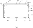
- Fig.1 is a main view of a display panel according to some embodiments of the present disclosure.
- Fig.2 is a sectional view of the display panel and a backlight module taken along line A-A in Fig.1 .
- the backlight module provided in the present disclosure includes: a light bar (not shown in Fig.1 and Fig.2 ), a light guide plate 100 having a light incoming side and a light outgoing face, a rubber frame 300 arranged at exteriors of four edges of the light guide plate 100, an optical film 200 arranged on the light outgoing face of the light guide plate 100, and one or more spacers 400.
- the optical film 200 includes four edges, at least a portion of at least one edge among the four edges exceeds an edge of the light guide plate and is placed on the rubber frame 300, such that the rubber frame 300 supports the optical film 200.
- the one or more spacers 400 are located on the portion of the at least one edge of the optical film 200 that is placed on the rubber frame 300 and are located on a surface of the optical film 200 away from the rubber frame 300.
- the one or more spacers 400 are used to support a display panel 500.
- the light bar is located at the light incoming side of the light guide plate 100.
- the light bar may be an LED light bar but it is not limited thereto.
- At least a portion of at least one edge among the four edges of the optical film 200 is extended to exceed the edge of the light guide plate 100 and is placed on the rubber frame 300, the one or more spacers 400 are arranged on the portion of the optical film 200 that is placed on the rubber frame 300, such that the rubber frame 300 supports the optical film 200 and the one or more spacers 400 on the optical film 200 support the display panel 500.
- the one or more spacers 400 are made of a silicone material having a transmittance.
- the one or more spacers may not damage the display panel 500 while supporting the display panel 500; on the other hand, the transmittance and shape of the silicone may be adjusted according to needs, to adjust a brightness uniformity at an edge of the optical film 200.
- the optical film 200 includes four edges.
- the four edges includes a first edge located at the light incoming side of the light guide plate 100 and three edges other than the first edge. In a direction perpendicular to the light outgoing face, the first edge of the optical film and an edge of the light incoming side of the light guide plate are located in a same plane. At least a portion of each of the three edges of the optical film 200 exceeds an edge of the light guide plate 100 and is placed on the rubber frame 300.
- a spacer 400 is arranged at each of the three edges of the optical film 200.
- the edge of the optical film 200, an edge of the spacer 400 and an outer edge of the rubber frame are located in a same plane in a direction perpendicular to the light outgoing face of the light guide plate 100.
- the optical film extends out of the edge of the light guide plate 100 and abuts against an inner edge of the rubber frame 300.
- the edge of the optical film 200 may not exceed the light guide plate 100 and the rubber frame 300 supports the display panel 500; at the other three edges of the light guide plate 100, each of the three edges of the optical film 200 extends out of the light guide plate 100 and the spacer 400 supports the display panel 500.
- one or more edges of the optical film 200 may extend out of the light guide plate and may be supported by the rubber frame 300, and a spacer 400 is arranged at the one or two edges to support the display panel and prevent light leakage.
- the rubber frame 300 includes four edges.
- the four edges includes a first edge frame located at the light incoming side of the light guide plate 100 and three edge frames other than the first edge frame.
- First supporting faces 301 are provided at two ends of each edge frame of the three edge frames of the rubber frame 300, where the first supporting faces 301 are protruding and are used to support the display panel 500.
- a second supporting face 302 is provided at a center of each of the three edge frames, where the second supporting face 302 is sunk and is used to support the optical film 200. At least a portion of the optical film 200, exceeding an edge of the light guide plate 100, is placed on the second supporting face 302.
- the display panel 500 includes a first edge located at the light incoming side of the light guide plate 100 and three edges other than the first edge.
- the first edge of the display panel 500 is supported by the rubber frame 300.
- a center of each of the three edges of the display panel 500 is placed on the spacer 400 on a corresponding edge of the three edges of the optical film 200.
- Two ends of each of the three edges of the display panel 500 are placed on the first supporting faces 301 at two ends of a corresponding edge frame of the three edge frames of the rubber frame 300.
- the display panel 500 is supported by a whole edge of the rubber frame 300 at the light incoming side of the light guide plate 100, while the other three edges of display panel 500 each are supported by a three-point structure. That is, for each of the three edges of the display panel other than an edge at the light incoming side of the light guide plate 100, two ends are supported by the rubber frame 300 and a center is supported by one or more spacers 400 on the optical film 200. In this way, the display panel 500 is better supported, fixed and prevented from contraction. By supporting the center of each edge with the spacer 400 on the optical film 200, a distance L between the optical film 200 and the display region of the display panel 500 is increased, which prevents light leakage.
- At each edge of the three edges of the optical film 200 at least two spacers 400 are provided.
- three spacers 400 are provided.
- the at least two spacers 400 are spaced from each other by a same distance.
- the edge of the display panel 500 is supported by the three-point structure, a difference between a brightness at the two ends of the display panel 500 and a brightness at the center of the display panel 500 may be prevented by adjusting a transmittance and a shape of the silicone spacer 400.
- the second supporting face 302 and the first supporting face 301 there is a set distance between the second supporting face 302 and the first supporting face 301 in a direction perpendicular to the light outgoing face of the light guide plate 100.
- the set distance is larger than or equal to a sum of a thickness of the portion of the optical film 200 that is placed on the second supporting face 302 and a thickness of the spacer 400.
- a supporting height of the second supporting faces 302 of the rubber frame 300, the optical film 200 and the spacers 400 for supporting the display panel 500 together is required to be same as a supporting height of the first supporting faces 301 of the rubber frame 300 for supporting the display panel 500.
- the distance between the first supporting face 301 and the second supporting face 302 in the direction perpendicular to the light outgoing face of the light guide plate 100 is required to be same as a sum of a thickness of the optical film 200 and a thickness of the spacer 400.
- each of the three edges of the optical film 200 exceeds a corresponding edge of the light guide plate 100 by 0.5mm or more than 0.5mm.
- a distance L between the edge of the optical film 200 and the display region of the display panel 500 is increased by about 0.5mm, which better preventing light leakage.
- a display device is further provided in the present disclosure.
- the display device includes a backlight module, a display panel 500 and a backboard 600.
- the backlight module adopts the backlight module according to foregoing embodiments of the present disclosure.
- An edge of at least one side of the display panel 500 is supported by a spacer 400 on the optical film 200.
- the backboard 600 supports the backlight module and the display panel 500 and surrounds an exterior of the backlight module and the display panel 500.
- the display panel 500 includes a first edge at the light incoming side of the light guide plate 100 and three edges other than the first edge.
- the first edge of the display panel 500 is supported by the rubber frame 300.
- Each of the three edges of the display panel 500 is placed on the spacer 400 on a corresponding edge among the three edges of the optical film 200.
- an edge of the optical film 200 may not exceed the light guide plate 100 and the display panel 500 is supported by the rubber frame 300.
- three edges of the optical film 200 each exceed the light guide plate 100 and the display panel 500 is supported by spacers 400.
- the first edge of the display panel is placed on the first edge frame of the rubber frame 300 and is supported by the first edge frame of the rubber frame 300.
- Two ends of each edge of the three edges of the display panel 500 other than the first edge are placed on first supporting faces 301 at two ends of a corresponding edge frame of the rubber frame 300 other than the first edge frame, and a center of each edge of the three edges of the display panel 500 other than the first edge is placed on a spacer 400 on a corresponding edge of the three edges of the optical film 200, such that the two ends of each of the three edges of the display panel 500 are supported by the first supporting faces 301 and the center of each of the three edges of the display panel 500 is supported by the spacer 400.
- the display panel 500 is supported by a whole edge of the rubber frame 300 at the light incoming side of the light guide plate 100, while the other three edges of display panel 500 each are supported by a three-point structure rather than a whole edge of the rubber frame 300. That is, for each of the three edges of the display panel other than the edge at the light incoming side of the light guide plate 100, two ends are supported by the rubber frame 300 and a center is supported by one or more spacers 400 on the optical film 200. In this way, two ends of each edge of the display panel 500 are still supported by the rubber frame 300 and the display panel 500 is better supported, fixed and prevented from contraction. By supporting the center of each edge with the spacer 400 on the optical film 200, a distance between the optical film 200 and the display region of the display panel 500 is increased, which prevents light leakage.
- At least one edge of the optical film is extended, such that at least a portion of the at least one edge of the optical film exceed the edge of the light guide plate and is placed on the rubber frame.
- a spacer is arranged at the at least one edge of the optical film to support the display panel.
Landscapes
- Physics & Mathematics (AREA)
- Nonlinear Science (AREA)
- General Physics & Mathematics (AREA)
- Optics & Photonics (AREA)
- Mathematical Physics (AREA)
- Chemical & Material Sciences (AREA)
- Crystallography & Structural Chemistry (AREA)
- Liquid Crystal (AREA)
- Planar Illumination Modules (AREA)
Abstract
Description
- This application claims a priority to Chinese Patent Application No.
201710750908.8 filed on August 28, 2017 - The present disclosure relates to the field of display technology, in particular to a backlight module and a display device.
- Liquid crystal display (LCD) is a kind of flat-panel display. Backlight module is a key component for LCD and serves as light source for LCD when the LCD works. As the rapid development of smart phones, backlight module with high brightness, narrow bezel and optimal image quality is required in the market. In the evolution of narrow-bezel LCD, the quality of backlight is decreased and particularly, a problem of bright line inside the backlight module is caused.
- The present disclosure provided a backlight module and a display device.
- In a first aspect, the present disclosure provided a backlight module. The backlight module includes: a light guide plate, having a light incoming side and a light outgoing face; a rubber frame, arranged at four edges of the light guide plate; an optical film, arranged on the light outgoing face of the light guide plate and having four edges, where at least a portion of at least one edge among the four edges of the optical film exceeds an edge of the light guide plate and is placed on the rubber frame such that the rubber frame supports the optical film; and one or more spacers, where the one or more spacers are located on the portion of the at least one edge of the optical film that is placed on the rubber frame and are located on a surface of the optical film away from the rubber frame, and the one or more spacers are used to support a display panel on the backlight module.
- Optionally, the one or more spacers are silicone spacers having a set transmittance.
- Optionally, the four edges includes a first edge located at the light incoming side of the light guide plate and three edges in addition to the first edge, and in a direction perpendicular to the light outgoing face, the first edge of the optical film and an edge of the light incoming side of the light guide plate are located in a same plane. At least a portion of each of the three edges of the optical film exceeds an edge of the light guide plate and is placed on the rubber frame, and the one or more spacers are arranged at each of the three edges of the optical film.
- Optionally, the rubber frame includes four edge frames and the four edge frames comprises a first edge frame located at the light incoming side of the light guide plate and three edge frames in addition to the first edge frame. First supporting faces are provided at two ends of each edge frame of the three edge frames of the rubber frame, the first supporting faces being protruding and used to support the display panel. A second supporting face is provided at a center of each of the three edge frames, the second supporting face being sunk and used to support the optical film. The at least the portion of each of the three edges of the optical film, exceeding the edge of the light guide plate, is placed on the second supporting face.
- Optionally, at a center of each edge of the three edges of the optical film, the edge of the optical film, an edge of the one or more spacers and an outer edge of the rubber frame are located in a same plane in the direction perpendicular to the light outgoing face of the light guide plate. At two ends of each edge of the three edges of the optical film, the optical film extends out of the edge of the light guide plate and abuts against an inner edge of the rubber frame.
- Optionally, the one or more spacers are spaced from each other by a same distance on a corresponding edge of the three edges.
- Optionally, there is a set distance between the second supporting face and the first supporting face in the direction perpendicular to the light outgoing face of the light guide plate, and the set distance is larger than or equal to a sum of a thickness of the portion of the optical film that is placed on the second supporting face and a thickness of the one or more spacers.
- Optionally, at least two spacers are provided at each edge of the three edges of the optical film.
- Optionally, each of the three edges of the optical film exceeds a corresponding edge of the light guide plate by 0.5mm or more than 0.5mm.
- In a second aspect, the present disclosure provides a display device. The display device includes: the backlight module in the first aspect, a display panel and a backboard. The backboard supports the backlight module and the display panel and surrounds an exterior of the backlight module and the display panel. At least one edge of four edges of the display panel is supported by the one or more spacers on the optical film.
- Optionally, the display panel includes a first edge at the light incoming side of the light guide plate and three edges in addition to the first edge, the first edge of the display panel is supported by the rubber frame, and each of the three edges of the display panel is placed on the one or more spacers on a corresponding edge of the three edges of the optical film.
- Optionally, the first edge of the display panel is placed on the first edge frame of the rubber frame and is supported by the first edge frame of the rubber frame, two ends of each edge of the three edges of the display panel are placed on the first supporting faces at the two ends of a corresponding edge frame of the rubber frame, and a center of each edge of the three edges of the display panel is placed on the one or more spacers on a corresponding edge of the three edges of the optical film, such that the two ends of each of the three edges of the display panel are supported by the first supporting faces and the center of each of the three edges of the display panel is supported by the one or more spacers.
-
-
Fig.1 is a main view of a display panel according to some embodiments of the present disclosure; -
Fig.2 is a sectional view of the display panel and a backlight module taken along line A-A inFig.1 ; and -
Fig.3 is a sectional view of the display panel and a backlight module taken along line B-B inFig.1 . - To better clarify objectives, technical solutions and advantages of the present disclosure, the technical solutions of the present disclosure are described in a clear and complete way in conjunction with drawings in the present disclosure. Apparently, the described embodiments are only a part of rather than all of embodiments of the present application. All other embodiments obtained by those ordinary skilled in the art based on the described embodiments fall within the protection scope of the present disclosure.
- In relevant technology, when a bezel of a display panel is too narrow, a distance between an optical film and a display region of a display panel is too small and light leakage may be caused. With the backlight module and the display device provided in the present disclosure, the light leakage of the backlight module caused when the bezel of the display panel is too small can be solved effectively.
- Reference can be made to
Fig.1 andFig.2 .Fig.1 is a main view of a display panel according to some embodiments of the present disclosure.Fig.2 is a sectional view of the display panel and a backlight module taken along line A-A inFig.1 . As shown inFig.1 andFig.2 , the backlight module provided in the present disclosure includes: a light bar (not shown inFig.1 andFig.2 ), alight guide plate 100 having a light incoming side and a light outgoing face, arubber frame 300 arranged at exteriors of four edges of thelight guide plate 100, anoptical film 200 arranged on the light outgoing face of thelight guide plate 100, and one ormore spacers 400. Theoptical film 200 includes four edges, at least a portion of at least one edge among the four edges exceeds an edge of the light guide plate and is placed on therubber frame 300, such that therubber frame 300 supports theoptical film 200. The one ormore spacers 400 are located on the portion of the at least one edge of theoptical film 200 that is placed on therubber frame 300 and are located on a surface of theoptical film 200 away from therubber frame 300. The one ormore spacers 400 are used to support adisplay panel 500. The light bar is located at the light incoming side of thelight guide plate 100. The light bar may be an LED light bar but it is not limited thereto. - In the backlight module and the display device provided in some embodiments of the present disclosure, at least a portion of at least one edge among the four edges of the
optical film 200 is extended to exceed the edge of thelight guide plate 100 and is placed on therubber frame 300, the one ormore spacers 400 are arranged on the portion of theoptical film 200 that is placed on therubber frame 300, such that therubber frame 300 supports theoptical film 200 and the one ormore spacers 400 on theoptical film 200 support thedisplay panel 500. Compared with a manner that the rubber frame supports the display panel in relevant technology, since at least one edge of theoptical film 200 extends out by a certain distance, a distance between theoptical film 200 and a display region of thedisplay panel 500 is increased, thereby effectively solving light leakage caused when the bezel of the display panel in the relevant technology is too small (for example, equal to or smaller than 2mm). - In an optional embodiment of the present disclosure, the one or
more spacers 400 are made of a silicone material having a transmittance. By using the silicone material, on one hand, the one or more spacers may not damage thedisplay panel 500 while supporting thedisplay panel 500; on the other hand, the transmittance and shape of the silicone may be adjusted according to needs, to adjust a brightness uniformity at an edge of theoptical film 200. - In addition, in an optional embodiment of the present disclosure, as shown in
Fig.1 to Fig.3 , theoptical film 200 includes four edges. The four edges includes a first edge located at the light incoming side of thelight guide plate 100 and three edges other than the first edge. In a direction perpendicular to the light outgoing face, the first edge of the optical film and an edge of the light incoming side of the light guide plate are located in a same plane. At least a portion of each of the three edges of theoptical film 200 exceeds an edge of thelight guide plate 100 and is placed on therubber frame 300. Aspacer 400 is arranged at each of the three edges of theoptical film 200. - Optionally, at a center of each edge of the three edges of the
optical film 200, the edge of theoptical film 200, an edge of thespacer 400 and an outer edge of the rubber frame are located in a same plane in a direction perpendicular to the light outgoing face of thelight guide plate 100. At two ends of each edge of the three edges of theoptical film 200, the optical film extends out of the edge of thelight guide plate 100 and abuts against an inner edge of therubber frame 300. - In the above solution, at the light incoming side of the
light guide plate 100, the edge of theoptical film 200 may not exceed thelight guide plate 100 and therubber frame 300 supports thedisplay panel 500; at the other three edges of thelight guide plate 100, each of the three edges of theoptical film 200 extends out of thelight guide plate 100 and thespacer 400 supports thedisplay panel 500. - It should be noted that is not limited to a solution where all the three edges of the
optical film 200 extend out of thelight guide plate 100. According to actual needs, one or more edges of theoptical film 200 may extend out of the light guide plate and may be supported by therubber frame 300, and aspacer 400 is arranged at the one or two edges to support the display panel and prevent light leakage. - In an optional embodiment of the present disclosure, as shown in
Fig.1 to Fig.3 , therubber frame 300 includes four edges. The four edges includes a first edge frame located at the light incoming side of thelight guide plate 100 and three edge frames other than the first edge frame. First supporting faces 301 are provided at two ends of each edge frame of the three edge frames of therubber frame 300, where the first supporting faces 301 are protruding and are used to support thedisplay panel 500. A second supportingface 302 is provided at a center of each of the three edge frames, where the second supportingface 302 is sunk and is used to support theoptical film 200. At least a portion of theoptical film 200, exceeding an edge of thelight guide plate 100, is placed on the second supportingface 302. - The
display panel 500 includes a first edge located at the light incoming side of thelight guide plate 100 and three edges other than the first edge. The first edge of thedisplay panel 500 is supported by therubber frame 300. A center of each of the three edges of thedisplay panel 500 is placed on thespacer 400 on a corresponding edge of the three edges of theoptical film 200. Two ends of each of the three edges of thedisplay panel 500 are placed on the first supporting faces 301 at two ends of a corresponding edge frame of the three edge frames of therubber frame 300. - In the above solution, the
display panel 500 is supported by a whole edge of therubber frame 300 at the light incoming side of thelight guide plate 100, while the other three edges ofdisplay panel 500 each are supported by a three-point structure. That is, for each of the three edges of the display panel other than an edge at the light incoming side of thelight guide plate 100, two ends are supported by therubber frame 300 and a center is supported by one ormore spacers 400 on theoptical film 200. In this way, thedisplay panel 500 is better supported, fixed and prevented from contraction. By supporting the center of each edge with thespacer 400 on theoptical film 200, a distance L between theoptical film 200 and the display region of thedisplay panel 500 is increased, which prevents light leakage. - Optionally, as shown in
Fig.2 , at each edge of the three edges of theoptical film 200, at least twospacers 400 are provided. For example, threespacers 400 are provided. The at least twospacers 400 are spaced from each other by a same distance. - In addition, since the edge of the
display panel 500 is supported by the three-point structure, a difference between a brightness at the two ends of thedisplay panel 500 and a brightness at the center of thedisplay panel 500 may be prevented by adjusting a transmittance and a shape of thesilicone spacer 400. - Furthermore, in an optional embodiment of the present disclosure, there is a set distance between the second supporting
face 302 and the first supportingface 301 in a direction perpendicular to the light outgoing face of thelight guide plate 100. The set distance is larger than or equal to a sum of a thickness of the portion of theoptical film 200 that is placed on the second supportingface 302 and a thickness of thespacer 400. - In the above solution, since the
display panel 500 is supported by therubber frame 300 and thespacers 400 together, a supporting height of the second supporting faces 302 of therubber frame 300, theoptical film 200 and thespacers 400 for supporting thedisplay panel 500 together is required to be same as a supporting height of the first supporting faces 301 of therubber frame 300 for supporting thedisplay panel 500. The distance between the first supportingface 301 and the second supportingface 302 in the direction perpendicular to the light outgoing face of thelight guide plate 100 is required to be same as a sum of a thickness of theoptical film 200 and a thickness of thespacer 400. - In addition, in an embodiment of the present disclosure, each of the three edges of the
optical film 200 exceeds a corresponding edge of thelight guide plate 100 by 0.5mm or more than 0.5mm. - Compared with relevant technology, in the above solution, a distance L between the edge of the
optical film 200 and the display region of thedisplay panel 500 is increased by about 0.5mm, which better preventing light leakage. - In addition, as shown in
Fig.3 , a display device is further provided in the present disclosure. The display device includes a backlight module, adisplay panel 500 and abackboard 600. The backlight module adopts the backlight module according to foregoing embodiments of the present disclosure. An edge of at least one side of thedisplay panel 500 is supported by aspacer 400 on theoptical film 200. Thebackboard 600 supports the backlight module and thedisplay panel 500 and surrounds an exterior of the backlight module and thedisplay panel 500. - In an optional embodiment of the present disclosure, as shown in
Fig.2 , thedisplay panel 500 includes a first edge at the light incoming side of thelight guide plate 100 and three edges other than the first edge. The first edge of thedisplay panel 500 is supported by therubber frame 300. Each of the three edges of thedisplay panel 500 is placed on thespacer 400 on a corresponding edge among the three edges of theoptical film 200. - In the above solution, at the light incoming side of the
light guide plate 100, an edge of theoptical film 200 may not exceed thelight guide plate 100 and thedisplay panel 500 is supported by therubber frame 300. At other three edges of thelight guide plate 100, three edges of theoptical film 200 each exceed thelight guide plate 100 and thedisplay panel 500 is supported byspacers 400. - Optionally, as shown in
Fig.1 to Fig.3 , the first edge of the display panel is placed on the first edge frame of therubber frame 300 and is supported by the first edge frame of therubber frame 300. Two ends of each edge of the three edges of thedisplay panel 500 other than the first edge are placed on first supporting faces 301 at two ends of a corresponding edge frame of therubber frame 300 other than the first edge frame, and a center of each edge of the three edges of thedisplay panel 500 other than the first edge is placed on aspacer 400 on a corresponding edge of the three edges of theoptical film 200, such that the two ends of each of the three edges of thedisplay panel 500 are supported by the first supporting faces 301 and the center of each of the three edges of thedisplay panel 500 is supported by thespacer 400. - In the above solution, the
display panel 500 is supported by a whole edge of therubber frame 300 at the light incoming side of thelight guide plate 100, while the other three edges ofdisplay panel 500 each are supported by a three-point structure rather than a whole edge of therubber frame 300. That is, for each of the three edges of the display panel other than the edge at the light incoming side of thelight guide plate 100, two ends are supported by therubber frame 300 and a center is supported by one ormore spacers 400 on theoptical film 200. In this way, two ends of each edge of thedisplay panel 500 are still supported by therubber frame 300 and thedisplay panel 500 is better supported, fixed and prevented from contraction. By supporting the center of each edge with thespacer 400 on theoptical film 200, a distance between theoptical film 200 and the display region of thedisplay panel 500 is increased, which prevents light leakage. - In the backlight module and the display device provided in the present disclosure, at least one edge of the optical film is extended, such that at least a portion of the at least one edge of the optical film exceed the edge of the light guide plate and is placed on the rubber frame. A spacer is arranged at the at least one edge of the optical film to support the display panel. Compared with a manner that the rubber frame supports the display panel in relevant technology, since the optical film extends out, a distance between the optical film and a display region of the display panel is increased, thereby effectively solving light leakage caused when a bezel of the display panel in the relevant technology is too small (for example, equal to or smaller than 2mm).
- Optional embodiments are described hereinabove. It should be noted that various improvements and replacements can be made by the ordinary skilled in the art without departing from the principle of the present disclosure. The improvements and replacements all fall within the protection scope of the present disclosure.
Claims (12)
- A backlight module, comprising:a light guide plate, including a light incoming side and a light outgoing face;a rubber frame, arranged at four edges of the light guide plate;an optical film, arranged on the light outgoing face of the light guide plate and including four edges, wherein at least a portion of at least one edge among the four edges of the optical film exceeds an edge of the light guide plate and is placed on the rubber frame, the rubber frame supports the optical film; andone or more spacers, wherein the one or more spacers are located on the portion of the at least one edge among the four edges of the optical film that is placed on the rubber frame and are located on a surface of the optical film away from the rubber frame, and the one or more spacers are used to support a display panel on the backlight module.
- The backlight module according to claim 1, wherein the one or more spacers are silicone spacers having a set transmittance.
- The backlight module according to claim 1 or 2, wherein the four edges comprises a first edge located at the light incoming side of the light guide plate and three edges other than the first edge, and in a direction perpendicular to the light outgoing face, the first edge of the optical film and an edge of the light incoming side of the light guide plate are located in a same plane; and
wherein at least a portion of each of the three edges of the optical film exceeds an edge of the light guide plate and is placed on the rubber frame, and the one or more spacers are arranged at each of the three edges of the optical film. - The backlight module according to claim 3, wherein the rubber frame comprises four edge frames and the four edge frames comprises a first edge frame located at the light incoming side of the light guide plate and three edge frames other than the first edge frame; first supporting faces are provided at two ends of each edge frame of the three edge frames of the rubber frame, the first supporting faces being protruding and supporting the display panel; a second supporting face is provided at a center of each of the three edge frames, the second supporting face being sunk and used to support the optical film; and the at least the portion of each of the three edges of the optical film that exceeds the edge of the light guide plate is placed on the second supporting face.
- The backlight module according to claim 4, wherein at a center of each edge of the three edges of the optical film, the edge of the optical film, an edge of the one or more spacers and an outer edge of the rubber frame are located in a same plane in the direction perpendicular to the light outgoing face of the light guide plate; and
wherein at two ends of each edge of the three edges of the optical film, the optical film extends out of the edge of the light guide plate and abuts against an inner edge of the rubber frame. - The backlight module according to any one of claims 3-5, wherein the one or more spacers are spaced from each other by a substantively same distance on a corresponding edge of the three edges of the optical film.
- The backlight module according to claim 4, wherein there is a set distance between the second supporting face and the first supporting face in the direction perpendicular to the light outgoing face of the light guide plate, and the set distance is larger than or equal to a sum of a thickness of the portion of the optical film that is placed on the second supporting face and a thickness of the one or more spacers.
- The backlight module according to any one of claims 1-7, wherein at least two spacers are provided at each of the three edges of the optical film.
- The backlight module according to any one of claims 3-8, wherein each of the three edges of the optical film exceeds a corresponding edge of the light guide plate by 0.5mm or more than 0.5mm.
- A display device, comprising:the backlight module according to any one of claims 1-9;a display panel; anda backboard, supporting the backlight module and the display panel and surrounding an exterior of the backlight module and the display panel;wherein at least one edge of four edges of the display panel is supported by the one or more spacers on the optical film.
- The display device according to claim 10, wherein the display device comprises the backlight module according to claim 3, the display panel comprises a first edge at the light incoming side of the light guide plate and three edges other than the first edge, the first edge of the display panel is supported by the rubber frame, and each of the three edges of the display panel is placed on the one or more spacers on a corresponding edge of the three edges of the optical film.
- The display device according to claim 11, wherein the display device comprises the backlight module according to claim 4, the first edge of the display panel is placed on the first edge frame of the rubber frame and is supported by the first edge frame of the rubber frame, two ends of each edge of the three edges of the display panel are placed on first supporting faces at the two ends of a corresponding edge frame of the rubber frame, and a center of each edge of the three edges of the display panel is placed on the one or more spacers on a corresponding edge of the three edges of the optical film, two ends of each of the three edges of the display panel are supported by the first supporting faces and the center of each of the three edges of the display panel is supported by the one or more spacers.
Applications Claiming Priority (2)
| Application Number | Priority Date | Filing Date | Title |
|---|---|---|---|
| CN201710750908.8A CN109426032B (en) | 2017-08-28 | 2017-08-28 | Backlight module and display device |
| PCT/CN2018/092414 WO2019041986A1 (en) | 2017-08-28 | 2018-06-22 | Backlight module and display device |
Publications (2)
| Publication Number | Publication Date |
|---|---|
| EP3677954A1 true EP3677954A1 (en) | 2020-07-08 |
| EP3677954A4 EP3677954A4 (en) | 2021-05-26 |
Family
ID=65502544
Family Applications (1)
| Application Number | Title | Priority Date | Filing Date |
|---|---|---|---|
| EP18851856.7A Withdrawn EP3677954A4 (en) | 2017-08-28 | 2018-06-22 | Backlight module and display device |
Country Status (4)
| Country | Link |
|---|---|
| US (1) | US10908458B2 (en) |
| EP (1) | EP3677954A4 (en) |
| CN (1) | CN109426032B (en) |
| WO (1) | WO2019041986A1 (en) |
Families Citing this family (4)
| Publication number | Priority date | Publication date | Assignee | Title |
|---|---|---|---|---|
| CN111025755A (en) * | 2019-12-16 | 2020-04-17 | 武汉华星光电技术有限公司 | Backlight module and display device |
| CN113589566A (en) | 2020-04-30 | 2021-11-02 | 群创光电股份有限公司 | Electronic device with curved surface and manufacturing method thereof |
| CN113970857A (en) * | 2020-07-23 | 2022-01-25 | 合肥鑫晟光电科技有限公司 | Display device and method for manufacturing the same |
| CN116168615B (en) * | 2023-02-28 | 2025-08-05 | 合肥京东方光电科技有限公司 | Back panel, backlight module and display device |
Family Cites Families (10)
| Publication number | Priority date | Publication date | Assignee | Title |
|---|---|---|---|---|
| DE10243215A1 (en) * | 2002-09-17 | 2004-03-25 | Tesa Ag | Adhesive strip used in the manufacture of liquid crystal displays has two surfaces and a support with two supporting surfaces with an adhesive layer arranged on both surfaces |
| KR20110028142A (en) | 2009-09-11 | 2011-03-17 | 엘지디스플레이 주식회사 | Backlight reflector and liquid crystal display device having same |
| JP2012242765A (en) * | 2011-05-24 | 2012-12-10 | Japan Display East Co Ltd | Liquid crystal display device |
| CN203349083U (en) * | 2013-06-28 | 2013-12-18 | 上海天马微电子有限公司 | Backlight module and liquid crystal display device |
| KR20150114113A (en) * | 2014-03-31 | 2015-10-12 | 삼성디스플레이 주식회사 | Liquid crystal display device |
| CN104534363A (en) * | 2014-12-31 | 2015-04-22 | 深圳市华星光电技术有限公司 | Backlight module and liquid crystal display with backlight module |
| KR20160126160A (en) * | 2015-04-22 | 2016-11-02 | 삼성디스플레이 주식회사 | Display device and manufacturing method thereof |
| CN205643976U (en) * | 2016-05-27 | 2016-10-12 | 京东方科技集团股份有限公司 | Backlight module and display device |
| JP2017223834A (en) * | 2016-06-15 | 2017-12-21 | 株式会社ジャパンディスプレイ | Backlight device and display device including the same |
| CN106773244A (en) * | 2016-12-23 | 2017-05-31 | 武汉华星光电技术有限公司 | A kind of display module |
-
2017
- 2017-08-28 CN CN201710750908.8A patent/CN109426032B/en not_active Expired - Fee Related
-
2018
- 2018-06-22 WO PCT/CN2018/092414 patent/WO2019041986A1/en not_active Ceased
- 2018-06-22 US US16/346,502 patent/US10908458B2/en not_active Expired - Fee Related
- 2018-06-22 EP EP18851856.7A patent/EP3677954A4/en not_active Withdrawn
Also Published As
| Publication number | Publication date |
|---|---|
| US10908458B2 (en) | 2021-02-02 |
| US20190294002A1 (en) | 2019-09-26 |
| WO2019041986A1 (en) | 2019-03-07 |
| EP3677954A4 (en) | 2021-05-26 |
| CN109426032B (en) | 2020-04-24 |
| CN109426032A (en) | 2019-03-05 |
Similar Documents
| Publication | Publication Date | Title |
|---|---|---|
| US9766487B2 (en) | Curved liquid crystal display device | |
| US10908458B2 (en) | Backlight module and display device for achieving brightness uniformity | |
| KR102301094B1 (en) | Display device | |
| US10132990B2 (en) | Backlight module and display device | |
| US9366804B2 (en) | Backplane and backlight module and liquid crystal display device using same | |
| US9052541B2 (en) | LCD module and LCD device | |
| US20190019445A1 (en) | Backlight assembly and display device | |
| US9810935B2 (en) | Display device | |
| US20140063404A1 (en) | Lcd module and lcd device | |
| US9885904B2 (en) | Display device | |
| KR102178198B1 (en) | Liquid crystal display device | |
| US10247859B2 (en) | Display panel and display device | |
| US20170108640A1 (en) | Backlight module and display device | |
| US9983426B2 (en) | Display module and display device comprising display module | |
| US10114244B2 (en) | Curved display device | |
| US8749730B2 (en) | Edge-lit backlight module and LCD device | |
| US10132989B2 (en) | Backlight module and display device | |
| US20160341863A1 (en) | Light Guide Plate and Backlight Module with the Same | |
| US10185078B2 (en) | Backlight module and display device | |
| JP6200758B2 (en) | Liquid crystal display | |
| US10203445B2 (en) | Backlight unit, display panel and display device | |
| US20200241191A1 (en) | Light guide plate, backlight and display device | |
| KR101604488B1 (en) | Backlight unit and liquid crystal display device having the same | |
| KR20160080857A (en) | Back light unit and liquid crystal display device having the same | |
| US20180356581A1 (en) | Backlight module and display device |
Legal Events
| Date | Code | Title | Description |
|---|---|---|---|
| STAA | Information on the status of an ep patent application or granted ep patent |
Free format text: STATUS: THE INTERNATIONAL PUBLICATION HAS BEEN MADE |
|
| PUAI | Public reference made under article 153(3) epc to a published international application that has entered the european phase |
Free format text: ORIGINAL CODE: 0009012 |
|
| STAA | Information on the status of an ep patent application or granted ep patent |
Free format text: STATUS: REQUEST FOR EXAMINATION WAS MADE |
|
| 17P | Request for examination filed |
Effective date: 20190410 |
|
| AK | Designated contracting states |
Kind code of ref document: A1 Designated state(s): AL AT BE BG CH CY CZ DE DK EE ES FI FR GB GR HR HU IE IS IT LI LT LU LV MC MK MT NL NO PL PT RO RS SE SI SK SM TR |
|
| AX | Request for extension of the european patent |
Extension state: BA ME |
|
| DAV | Request for validation of the european patent (deleted) | ||
| DAX | Request for extension of the european patent (deleted) | ||
| A4 | Supplementary search report drawn up and despatched |
Effective date: 20210429 |
|
| RIC1 | Information provided on ipc code assigned before grant |
Ipc: G02F 1/1335 20060101AFI20210422BHEP Ipc: F21V 8/00 20060101ALI20210422BHEP Ipc: G02F 1/1333 20060101ALI20210422BHEP |
|
| STAA | Information on the status of an ep patent application or granted ep patent |
Free format text: STATUS: THE APPLICATION HAS BEEN WITHDRAWN |
|
| 18W | Application withdrawn |
Effective date: 20220406 |