EP3677932A1 - Millimeter wave security inspection apparatus and method for inspecting human or article - Google Patents
Millimeter wave security inspection apparatus and method for inspecting human or article Download PDFInfo
- Publication number
- EP3677932A1 EP3677932A1 EP19219848.9A EP19219848A EP3677932A1 EP 3677932 A1 EP3677932 A1 EP 3677932A1 EP 19219848 A EP19219848 A EP 19219848A EP 3677932 A1 EP3677932 A1 EP 3677932A1
- Authority
- EP
- European Patent Office
- Prior art keywords
- millimeter wave
- door
- door device
- article
- transceiver
- Prior art date
- Legal status (The legal status is an assumption and is not a legal conclusion. Google has not performed a legal analysis and makes no representation as to the accuracy of the status listed.)
- Granted
Links
Images




Classifications
-
- G—PHYSICS
- G01—MEASURING; TESTING
- G01V—GEOPHYSICS; GRAVITATIONAL MEASUREMENTS; DETECTING MASSES OR OBJECTS; TAGS
- G01V8/00—Prospecting or detecting by optical means
- G01V8/005—Prospecting or detecting by optical means operating with millimetre waves, e.g. measuring the black losey radiation
-
- G—PHYSICS
- G01—MEASURING; TESTING
- G01S—RADIO DIRECTION-FINDING; RADIO NAVIGATION; DETERMINING DISTANCE OR VELOCITY BY USE OF RADIO WAVES; LOCATING OR PRESENCE-DETECTING BY USE OF THE REFLECTION OR RERADIATION OF RADIO WAVES; ANALOGOUS ARRANGEMENTS USING OTHER WAVES
- G01S13/00—Systems using the reflection or reradiation of radio waves, e.g. radar systems; Analogous systems using reflection or reradiation of waves whose nature or wavelength is irrelevant or unspecified
- G01S13/88—Radar or analogous systems specially adapted for specific applications
- G01S13/887—Radar or analogous systems specially adapted for specific applications for detection of concealed objects, e.g. contraband or weapons
-
- G—PHYSICS
- G01—MEASURING; TESTING
- G01V—GEOPHYSICS; GRAVITATIONAL MEASUREMENTS; DETECTING MASSES OR OBJECTS; TAGS
- G01V8/00—Prospecting or detecting by optical means
- G01V8/10—Detecting, e.g. by using light barriers
- G01V8/20—Detecting, e.g. by using light barriers using multiple transmitters or receivers
-
- G—PHYSICS
- G03—PHOTOGRAPHY; CINEMATOGRAPHY; ANALOGOUS TECHNIQUES USING WAVES OTHER THAN OPTICAL WAVES; ELECTROGRAPHY; HOLOGRAPHY
- G03H—HOLOGRAPHIC PROCESSES OR APPARATUS
- G03H1/00—Holographic processes or apparatus using light, infrared or ultraviolet waves for obtaining holograms or for obtaining an image from them; Details peculiar thereto
-
- G—PHYSICS
- G03—PHOTOGRAPHY; CINEMATOGRAPHY; ANALOGOUS TECHNIQUES USING WAVES OTHER THAN OPTICAL WAVES; ELECTROGRAPHY; HOLOGRAPHY
- G03H—HOLOGRAPHIC PROCESSES OR APPARATUS
- G03H1/00—Holographic processes or apparatus using light, infrared or ultraviolet waves for obtaining holograms or for obtaining an image from them; Details peculiar thereto
- G03H1/0005—Adaptation of holography to specific applications
- G03H1/0011—Adaptation of holography to specific applications for security or authentication
Definitions
- At least one embodiment of the present disclosure relates to a technical field of security inspection, and more particularly, to a millimeter wave security inspection apparatus and a method for inspecting a human or article by using the millimeter wave security inspection apparatus.
- a security inspection apparatus such as a security inspection apparatus for inspecting a human
- CN203385856U discloses a millimeter wave three-dimensional holographic scanning imaging device comprising two millimeter wave transceiving antenna arrays horizontally positioned to perform double-sided scanning, a front side of the human is scanned by one of the two millimeter wave transceiving antenna arrays moving from top to bottom and a back side of the human is scanned by the other of the two millimeter wave transceiving antenna arrays moving from bottom to top.
- a millimeter wave imaging system with area array scanning where in order to scan both sides of the human, the human needs to turn if only one plane array is used (QPS 100), or two plane arrays are used to scan front and back sides of the human (QPS 200).
- QPS 100 plane array
- QPS 200 two plane arrays are used to scan front and back sides of the human
- two millimeter wave transceiving arrays linear arrays or area arrays
- the cost is high; if only one array of millimeter wave transceiving antennas is used, the human needs to turn, thereby reducing the passing rate.
- An object of the present disclosure is to solve at least one of the above and other problems and defects existing in the prior arts.
- a millimeter wave security inspection apparatus comprising: a door device comprising a first door and a second door arranged in a stacked mode, each of the first door and the second door being made of a material allowing a millimeter wave to penetrate there through; a millimeter wave transceiver provided between the first door and the second door and comprising an millimeter wave transceiving antenna array configured to transmit a millimeter wave signal to an entrance side and an exit side of the door device, respectively, and to receive the millimeter wave signal reflected from the entrance side and the exit side of the door device, respectively; and a linear driver, the millimeter wave transceiver being connected to the linear driver to be movable between the first door and the second door relative to the door device under driving of the linear driver, so as to scan a first side of an object to be inspected in a state where the object is positioned at the entrance side and to a second side of the object opposite to the first side
- the millimeter wave transceiver comprises: a first millimeter wave transceiver comprising a first millimeter wave transceiving antenna array configured to transmit the millimeter wave signal to the entrance side of the door device and to receive the millimeter wave signal reflected from the entrance side of the door device; and a second millimeter wave transceiver comprising a second millimeter wave transceiving antenna array configured to transmit the millimeter wave signal to the exit side of the door device and to receive the millimeter wave signal reflected from the exit side of the door device.
- the millimeter wave transceiving antenna array comprises: a first millimeter wave transceiving antenna subarray adapted to transmit the millimeter wave signal to the entrance side of the door device and receive the millimeter wave signal reflected from the entrance side of the door device; a second millimeter wave transceiving antenna subarray adapted to transmit the millimeter wave signal to the exit side of the door device and receive the millimeter wave signal reflected from the exit side of the door device; and a switch adapted to switch between the first millimeter wave transceiving antenna subarray and the second millimeter wave transceiving antenna subarray.
- the millimeter wave transceiving antenna array is a linear array arranged in a horizontal direction, and the millimeter wave transceiver is moveable vertically relative to the door device.
- the millimeter wave transceiving antenna array is a linear array arranged in a vertical direction, and the millimeter wave transceiver is moveable horizontally relative to the door device.
- the millimeter wave security inspection apparatus further comprises a controller adapted to generate a control signal and transmit the control signal to the linear driver so that the linear driver drives the millimeter wave transceiver to move.
- the first door and the second door each comprise: a door frame; a sliding door panel being slidable relative to the door frame; and a sliding door panel driver connected to the controller and adapted to drive the sliding door panel to slide under control of the controller.
- the sliding door panel comprises a first sliding door panel and a second sliding door panel slidable in opposite directions relative to the door frame.
- the linear driver comprises: a linear transmission mechanism comprising a driven wheel rotatably connected to the door device and a conveyor belt, the millimeter wave transceiver being connected to the conveyor belt, wherein the door frame is provided with an accommodating groove adapted to accommodate the linear transmission mechanism therein; and a driving mechanism adapted to drive the conveyor belt of the linear transmission mechanism to move, the driving mechanism being connected to the controller.
- the millimeter wave security inspection apparatus comprises two said linear transmission mechanisms arranged on two opposite sides of the door frame.
- the millimeter wave security inspection apparatus further comprises: a data processor being connected to the millimeter wave transceiver wirelessly or in a wired means, so as to receive scan data obtained by the millimeter wave transceiver and generate a millimeter wave holographic image; and a display connected to the data processor and adapted to receive and display the millimeter wave holographic image from the data processor.
- the millimeter wave security inspection apparatus further comprises an isolation device provided at the exit side of the door device, the isolation device being connected to the controller to be opened or closed under control of the controller.
- a method for inspecting a human or article by a millimeter wave security inspection apparatus comprises following steps:
- the step S2 comprises: during the movement of the millimeter wave transceiver from the scanning start position to the scanning end position, scanning a first side of a second human or article at the entrance side by a first millimeter wave transceiver or a first millimeter wave transceiving antenna subarray, and scanning a second side of a first human or article at the exit side by a second millimeter wave transceiver or a second the millimeter wave transceiving antenna subarray at the same time.
- the step S5 comprises: during the movement of the millimeter wave transceiver from the scanning end position to the scanning start position, scanning a first side of another human or article at the entrance side by the first millimeter wave transceiver or the first millimeter wave transceiving antenna subarray, and scanning a second side of the second human or article located at the exit side by the second millimeter wave transceiver or the second millimeter wave transceiving antenna subarray at the same time.
- the method further comprises steps of identifying whether the human or article carries a suspicious object and a position of the suspicious object and outputting identified information after generating the millimeter wave holographic image of the human or article.
- the method further comprises keeping an isolation device closed when the human or article is identified as carrying a suspicious object, and opening the isolation device if the human or article is identified as not carrying a suspicious object.
- a millimeter wave security inspection apparatus comprising: a door device comprising a first door and a second door arranged in a stacked mode, each of the first door and the second door being made of a material allowing a millimeter wave to penetrate there through; a millimeter wave transceiver arranged between the first door and the second door and comprising an millimeter wave transceiving antenna array configured to transmit a millimeter wave signal to an entrance side and an exit side of the door device, respectively, and to receive the millimeter wave signal reflected from the entrance side and the exit side of the door device, respectively; and a linear driver, the millimeter wave transceiver being connected to the linear driver to be movable between the first door and the second door relative to the door device under driving of the linear driver, so as to scan a first side of an object to be inspected in a state where the object is positioned at the entrance side and to a second side of the object opposite to the first side in
- Fig. 1 is a schematic structural view illustrating a millimeter wave security inspection apparatus 100 according to an exemplary embodiment of the present disclosure.
- the millimeter wave security inspection apparatus 100 comprises a door device 10, a millimeter wave transceiver 20 and a linear driver 30.
- the door device 10 comprises a first door and a second door arranged in a stacked manner, each of the first door and the second door being made of a material allowing a millimeter wave to penetrate there through, such as polytetrafluoroethylene, polyethylene, or the like.
- the millimeter wave transceiver 20 is provided between the first door and the second door, and comprises an millimeter wave transceiving antenna array 29 configured to transmit a millimeter wave signal to an entrance side and an exit side of the door device 10, respectively, and to receive the millimeter wave signal reflected from the entrance side and the exit side of the door device 10, respectively.
- the millimeter wave transceiver 20 is connected to the linear driver 30 so as to be movable in a vertical direction between the first door and the second door relative to the door device 10 under driving of the linear driver 30.
- the door device 10 When an object 200 to be inspected is positioned at the entrance side of the door device 10, the door device 10 is closed, then the millimeter wave transceiver 20 transmits the millimeter wave signal to the entrance side of the door device 10 and receives the millimeter wave signal reflected by the object 200 to be inspected at the entrance side of the door device 10, and a first side (e.g., a front side) of the object 200 is scanned by the millimeter wave transceiver 20 while the millimeter wave transceiver 20 is moved in the vertical direction (e.g., from top to bottom); after the first-side has been scanned, the door device 10 opens to form a passage, so as to allow the object 200 to pass through the door device 10; and after the object 200 has passed through the door device 10, the door device 10 is closed, and then the millimeter wave transceiver 20 transmits a millimeter wave signal to the exit side of the door device 10 and receives the millimeter wave signal reflected by the object 200 at the exit side of
- the millimeter wave security inspection apparatus 100 has a door-shaped structure so that the footprint area of the millimeter wave security inspection apparatus 100 is far smaller than that of the existing millimeter wave security inspection apparatus.
- the millimeter wave transceiver 20 comprises a millimeter wave emission source 21, a millimeter wave local oscillator 22, a first power divider 23, a second power divider 24, a first mixer 25, a second mixer 26, a I/Q demodulator 27, a switch 28 and the millimeter wave transceiving antenna array 29.
- the millimeter wave emission source 21 generates a millimeter wave signal
- the first power divider 23 is connected to the millimeter wave emission source 21 and divides the millimeter wave signal emitted by the millimeter wave emission source 21 into two millimeter wave sub-signals, one millimeter wave sub-signal is output to a transmitting antenna array of the millimeter wave transceiving antenna array 29, and other millimeter wave sub-signal divided by the first power divider 23 and one millimeter wave sub-signal output from the millimeter wave local oscillator 22 and divided by the second power divider 24 are mixed by the first mixer 25 to form a reference signal; the other millimeter wave sub-signal output from the millimeter wave local oscillator 22 and divided by the second power divider 24 and a millimeter wave signal received by a receiving antenna array of the millimeter wave transceiving antenna array 29 are mixed by the second mixer 26 to form a measurement signal; the measurement signal and the reference signal are demodulated by the I/Q demodulator
- the millimeter wave transceiving antenna array 29 is arranged on two opposite sides, and comprises a first millimeter wave transceiving antenna subarray 29-1 configured to transmit a millimeter wave signal to the entrance side of the door device 10 and to receive the millimeter wave signal reflected by the object 200 to be inspected at the entrance side of the door device 10, a second millimeter wave transceiving antenna subarray 29-2 configured to transmit a millimeter wave signal to the exit side of the door device 10 and to receive the millimeter wave signal reflected by the object 200 at the exit side of the door device 10, and a switch 28 adapted to switch the first millimeter wave transceiving antenna subarray 29-1 and the second millimeter wave transceiving antenna subarray 29-2.
- the switch 28 may switch among a plurality of transceiving units of the first millimeter wave transceiving antenna subarray 29-1, switch among a plurality of transceiving units of the second millimeter wave transceiving antenna subarray 29-2, and switch between the plurality of transceiving units of the first millimeter wave transceiving antenna subarray 29-1 and the plurality of transceiving elements of the second millimeter wave transceiving antenna subarray 29-2.
- a data processor 50 is connected to the first millimeter wave transceiving antenna subarray 29-1 and the second millimeter wave transceiving antenna subarray 29-2 by a wired or wireless connection to receive the data obtained by the first millimeter wave transceiving antenna subarray 29-1 and the second millimeter wave transceiving antenna subarray 29-2, respectively, and to generate corresponding millimeter wave hologram images, respectively.
- each of the first millimeter wave transceiving antenna subarray 29-1 and the second millimeter wave transceiving antenna subarray 29-2 is a linear array arranged in a horizontal direction, and the millimeter wave transceiver 20 is moveable vertically relative to the door device 10.
- the first millimeter wave transceiving antenna subarray 29-1 and the second millimeter wave transceiving antenna subarray 29-2 may also be linear arrays arranged in the vertical direction, and then the millimeter wave transceiver 20 may move horizontally relative to the door device 10.
- the first millimeter wave transceiving antenna subarray 29-1 and the second millimeter wave transceiving antenna subarray 29-2 may alternatively be an area array, for example, including but not limited to a rectangular area array.
- the millimeter wave security inspection apparatus 100 further comprises a controller 40 configured to generate a control signal and send the control signal to the linear driver 30 so that the linear driver 30 drives the millimeter wave transceiver 20 to move.
- the door device 10 is automatic screen door, wherein the first door and the second door each comprise a door frame 11 and sliding door panels 12, 13 (14, 15) slidable relative to the door frame 11; here, the door frame of the first door and the door frame of the second door are integrated. Further, the door device 10 further comprises a sliding door panel driver (not shown) connected to the controller 40 and adapted to drive the sliding door panels 12, 13, 14, 15 to slide under control of the controller 40.
- the sliding door panels 12, 13 (14, 15) comprise a first sliding door panel 12 (15) and a second sliding door panel 13 (14), the first sliding door panel 12 (15) and the second sliding door panel 13 (14) being slidable in two opposite directions relative to the door frame 11 to further shorten the opening and closing time of the door device 10, thereby improving the security inspection efficiency.
- the linear driver 30 comprises a linear transmission mechanism and a driving mechanism 31.
- the linear transmission mechanism comprises a driven wheel 32 rotatably connected to the door device 10 and a conveyor belt 33 (e.g., a toothed belt) connected to the driving mechanism 31, and the millimeter wave transceiver 20 is connected to the conveyor belt 33 to move under driving of the conveyor belt 33.
- the door frame 11 is provided with a receiving groove 111 located between the first door and the second door and adapted to receive the linear transmission mechanism.
- the driving mechanism 31 (such as a gear motor) is adapted to drive the conveyor belt 33 of the linear transmission mechanism to move, and is connected to the controller 40 to drive the millimeter wave transceiver 20 to move under control of the controller 40.
- the linear driver 30 may be of other types, such as a linear actuator, a piston cylinder, etc.
- the millimeter wave security inspection apparatus 100 may further comprise a data processor 50.
- the data processor 50 is connected to the millimeter wave transceiver 20 wirelessly or in a wired manner (for example, by a wire) to receive the data from the millimeter wave transceiver 20, and configured to generate the millimeter wave holographic image with high resolution by an image reconstruction algorithm, and to automatically identify a suspicious object by an automatic identification algorithm.
- the millimeter wave security inspection apparatus 100 may further comprise a display 60.
- the display 60 is connected to the data processor 50 and configured to receive and display the millimeter wave hologram image generated by the data processor 50.
- the controller 40 may be integrated with the data processor 50.
- the millimeter wave security inspection apparatus 100 further comprises an isolation device 70 provided at the exit side of the door device 10 and connected to the controller 40 to be opened or closed under control of the controller 40.
- the isolation device 70 will be opened if the object 200 does not carry any suspicious object, and if the object 200 carries a suspicious object, the isolation device is kept closed to intercept the object 200 and send out an alarm.
- millimeter wave transceiving antenna array 29 of the millimeter wave transceiver 20 are arranged in a double-sided manner, it will be appreciated by those skilled in the art that in some other embodiments of the present disclosure, two millimeter wave transceivers placed back-to-back and close proximity to each other may be used, including a first millimeter wave transceiver 20 and a second millimeter wave transceiver 20' (shown in Fig.
- the first millimeter wave transceiver 20 comprises a first millimeter wave transceiving antenna array configured to transmit a millimeter wave signal to the entrance side of the door device 10 and to receive the millimeter wave signal reflected by the object 200 to be inspected at the entrance side of the door device 10; and the second millimeter wave transceiver comprises a second millimeter wave transceiving antenna array configured to transmit a millimeter wave signal to the exit side of the door device 10 and to receive the millimeter wave signal reflected by the object 200 at the exit side of the door device 10. Since the two millimeter wave transceivers are used, it is possible to simultaneously inspect two objects 201, 202 positioning at the entrance side and the exit side of the door device 10, respectively.
- the data processor 50 is connected wirelessly or in a wired manner to the first millimeter wave transceiver 20 and the second millimeter wave transceiver 20' to receive the data from the first millimeter wave transceiver 20 and the second millimeter wave transceiver 20', respectively, so as to generate corresponding millimeter wave hologram images.
- the present disclosure also provides a method for inspecting a human or article by the millimeter wave security inspection apparatus, as shown in Fig. 10 , the method including following steps:
- the step S2 comprises: during the movement of the millimeter wave transceiver from the scanning start position to the scanning end position, scanning a first side of the second human or article 202 at the entrance side is scanned by the first millimeter wave transceiver 20 or by the first millimeter wave transceiving antenna subarray 29-1, and scanning a second side of the first human or article 201 at the exit side by the second millimeter wave transceiver 20' or by the second millimeter wave transceiving antenna subarray 29-2 at the same time, as shown in Fig. 9 .
- the step S5 comprises: during the movement of the millimeter wave transceiver from the scanning end position to the scanning start position, scanning a first side of other human or article 202 at the entrance side by the first millimeter wave transceiver 20 or the first millimeter wave transceiving antenna subarray 29-1, and scanning a second side of the second human or article 202 at the exit side by the second millimeter wave transceiver 20' or by the second millimeter wave transceiving antenna subarray 29-2 at the same time.
- the method may further optionally comprise steps of automatically identifying whether the human or article carries a suspicious object and a position of the suspicious object and outputting identified information after generating the millimeter wave holographic image of the human or article. This will contribute to quickly identify the suspicious object and prevent security risks and is particularly beneficial in airports, customs, and other applications where a quick determination of security risks is required.
- the method may further optionally comprise steps of keeping the isolation device 70 closed when the human or article is identified as carrying a suspicious object, and opening the isolation device 70 if the human or article is identified as not carrying any suspicious object.
Landscapes
- Physics & Mathematics (AREA)
- General Physics & Mathematics (AREA)
- Life Sciences & Earth Sciences (AREA)
- General Life Sciences & Earth Sciences (AREA)
- Geophysics (AREA)
- Engineering & Computer Science (AREA)
- Radar, Positioning & Navigation (AREA)
- Remote Sensing (AREA)
- Computer Security & Cryptography (AREA)
- Electromagnetism (AREA)
- Computer Networks & Wireless Communication (AREA)
- Radar Systems Or Details Thereof (AREA)
- Geophysics And Detection Of Objects (AREA)
Abstract
Description
- This application claims the priority benefit of Chinese Patent Application No.
201811631615.9 filed on December 28, 2018 - At least one embodiment of the present disclosure relates to a technical field of security inspection, and more particularly, to a millimeter wave security inspection apparatus and a method for inspecting a human or article by using the millimeter wave security inspection apparatus.
- In the prior arts, a security inspection apparatus, such as a security inspection apparatus for inspecting a human, usually operates with a millimeter wave imaging system. For example,
CN203385856U discloses a millimeter wave three-dimensional holographic scanning imaging device comprising two millimeter wave transceiving antenna arrays horizontally positioned to perform double-sided scanning, a front side of the human is scanned by one of the two millimeter wave transceiving antenna arrays moving from top to bottom and a back side of the human is scanned by the other of the two millimeter wave transceiving antenna arrays moving from bottom to top.US2015/0293221A1 of Rohad & Schwarz GmbH & Co. discloses a millimeter wave imaging system with area array scanning, where in order to scan both sides of the human, the human needs to turn if only one plane array is used (QPS 100), or two plane arrays are used to scan front and back sides of the human (QPS 200). Thus, in order to scan the front and back sides of the human, two millimeter wave transceiving arrays (linear arrays or area arrays) are used in the prior arts, so that the cost is high; if only one array of millimeter wave transceiving antennas is used, the human needs to turn, thereby reducing the passing rate. - An object of the present disclosure is to solve at least one of the above and other problems and defects existing in the prior arts.
- According to an exemplary embodiment of an aspect of the present disclosure, there is provided a millimeter wave security inspection apparatus, comprising: a door device comprising a first door and a second door arranged in a stacked mode, each of the first door and the second door being made of a material allowing a millimeter wave to penetrate there through; a millimeter wave transceiver provided between the first door and the second door and comprising an millimeter wave transceiving antenna array configured to transmit a millimeter wave signal to an entrance side and an exit side of the door device, respectively, and to receive the millimeter wave signal reflected from the entrance side and the exit side of the door device, respectively; and a linear driver, the millimeter wave transceiver being connected to the linear driver to be movable between the first door and the second door relative to the door device under driving of the linear driver, so as to scan a first side of an object to be inspected in a state where the object is positioned at the entrance side and to a second side of the object opposite to the first side in a state where the object is positioned at the exit side.
- In some embodiments, the millimeter wave transceiver comprises: a first millimeter wave transceiver comprising a first millimeter wave transceiving antenna array configured to transmit the millimeter wave signal to the entrance side of the door device and to receive the millimeter wave signal reflected from the entrance side of the door device; and a second millimeter wave transceiver comprising a second millimeter wave transceiving antenna array configured to transmit the millimeter wave signal to the exit side of the door device and to receive the millimeter wave signal reflected from the exit side of the door device.
- In some embodiments, the millimeter wave transceiving antenna array comprises: a first millimeter wave transceiving antenna subarray adapted to transmit the millimeter wave signal to the entrance side of the door device and receive the millimeter wave signal reflected from the entrance side of the door device; a second millimeter wave transceiving antenna subarray adapted to transmit the millimeter wave signal to the exit side of the door device and receive the millimeter wave signal reflected from the exit side of the door device; and a switch adapted to switch between the first millimeter wave transceiving antenna subarray and the second millimeter wave transceiving antenna subarray.
- In some embodiments, the millimeter wave transceiving antenna array is a linear array arranged in a horizontal direction, and the millimeter wave transceiver is moveable vertically relative to the door device.
- In some embodiments, the millimeter wave transceiving antenna array is a linear array arranged in a vertical direction, and the millimeter wave transceiver is moveable horizontally relative to the door device.
- In some embodiments, the millimeter wave security inspection apparatus further comprises a controller adapted to generate a control signal and transmit the control signal to the linear driver so that the linear driver drives the millimeter wave transceiver to move.
- In some embodiments, the first door and the second door each comprise: a door frame; a sliding door panel being slidable relative to the door frame; and a sliding door panel driver connected to the controller and adapted to drive the sliding door panel to slide under control of the controller.
- In some embodiments, the sliding door panel comprises a first sliding door panel and a second sliding door panel slidable in opposite directions relative to the door frame.
- In some embodiments, the linear driver comprises: a linear transmission mechanism comprising a driven wheel rotatably connected to the door device and a conveyor belt, the millimeter wave transceiver being connected to the conveyor belt, wherein the door frame is provided with an accommodating groove adapted to accommodate the linear transmission mechanism therein; and a driving mechanism adapted to drive the conveyor belt of the linear transmission mechanism to move, the driving mechanism being connected to the controller.
- In some embodiments, the millimeter wave security inspection apparatus comprises two said linear transmission mechanisms arranged on two opposite sides of the door frame.
- In some embodiments, the millimeter wave security inspection apparatus further comprises: a data processor being connected to the millimeter wave transceiver wirelessly or in a wired means, so as to receive scan data obtained by the millimeter wave transceiver and generate a millimeter wave holographic image; and a display connected to the data processor and adapted to receive and display the millimeter wave holographic image from the data processor.
- In some embodiments, the millimeter wave security inspection apparatus further comprises an isolation device provided at the exit side of the door device, the isolation device being connected to the controller to be opened or closed under control of the controller.
- According to an exemplary embodiment of another aspect of the present disclosure, there is provided a method for inspecting a human or article by a millimeter wave security inspection apparatus, the method comprises following steps:
- S1: positioning the human or article at an entrance side of a door device, and putting the millimeter wave transceiver in its scanning start position;
- S2: driving the millimeter wave transceiver to horizontally or vertically move continuously or intermittently from the scanning start position to a scanning end position by means of a linear driver so as to scan a first side of the human or article;
- S3: sending data obtained in a scanning process by the millimeter wave transceiver to a data processor during or after the scanning process;
- S4: opening a first door and a second door of the door device after the first side has been scanned, so that the human or article reaches an exit side of the door device through the door device;
- S5: driving the millimeter wave transceiver to horizontally or vertically move continuously or intermittently from the scanning end position to the scanning start position by means of the linear driver to scan a second side of the human or article opposite to the first side located at the exit side; and
- S6: processing, by the data processor, the data obtained by the millimeter wave transceiver to generate a millimeter wave holographic image of the human or article.
- In some embodiments, the step S2 comprises: during the movement of the millimeter wave transceiver from the scanning start position to the scanning end position, scanning a first side of a second human or article at the entrance side by a first millimeter wave transceiver or a first millimeter wave transceiving antenna subarray, and scanning a second side of a first human or article at the exit side by a second millimeter wave transceiver or a second the millimeter wave transceiving antenna subarray at the same time.
- In some embodiments, the step S5 comprises: during the movement of the millimeter wave transceiver from the scanning end position to the scanning start position, scanning a first side of another human or article at the entrance side by the first millimeter wave transceiver or the first millimeter wave transceiving antenna subarray, and scanning a second side of the second human or article located at the exit side by the second millimeter wave transceiver or the second millimeter wave transceiving antenna subarray at the same time.
- In some embodiments, the method further comprises steps of identifying whether the human or article carries a suspicious object and a position of the suspicious object and outputting identified information after generating the millimeter wave holographic image of the human or article.
- In some embodiments, the method further comprises keeping an isolation device closed when the human or article is identified as carrying a suspicious object, and opening the isolation device if the human or article is identified as not carrying a suspicious object.
- The above and other features of the present disclosure will become more apparent by describing in detail exemplary embodiments thereof with reference to the accompanying drawings, in which:
-
Fig. 1 is a schematic structural view illustrating a millimeter wave security inspection apparatus according to an exemplary embodiment of the present disclosure; -
Fig. 2 is a diagram of a working principle of a millimeter wave transceiver according to an exemplary embodiment of the present disclosure; -
Fig. 3 is a schematic structural view illustrating a millimeter wave security inspection apparatus according to another exemplary embodiment of the present disclosure; -
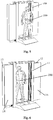
Fig. 4 is a perspective view illustrating a first-side (front-side) of an object to be inspected standing on an entrance side of a door device being scanned by a millimeter wave security inspection apparatus according to the present disclosure; -
Fig. 5 is a schematic view of a state in which the door device is opened after the first-side of an object to be inspected has been scanned by the millimeter wave security inspection apparatus according to the present disclosure; -
Fig. 6 is a schematic view of a state in which the inspected object passes through the door device of the millimeter wave security inspection apparatus; -
Fig. 7 is a schematic perspective view illustrating a second-side (back-side) of an object to be inspected standing on a exit side of a door device being scanned by a millimeter wave security apparatus according to the present disclosure; -
Fig. 8 is a schematic structural view illustrating a millimeter wave transceiver of a millimeter wave security inspection apparatus according to another exemplary embodiment of the present disclosure; -
Fig. 9 is a schematic structural view illustrating a millimeter wave security inspection apparatus according to yet another exemplary embodiment of the present disclosure, wherein the millimeter wave security inspection apparatus comprises an isolation device; and -
Fig. 10 is a flowchart of a method for inspecting a human or article according to an exemplary embodiment of the present disclosure. - Although the present disclosure will be fully described with reference to the accompanying drawings including the preferred embodiments of the disclosure, before the description, it should be understand any modifications may be made in the described contents herein by those skilled in the art and obtain advantageous effects of the disclosure at the same time. Therefore, the above description is to be understood as a broad disclosure for those skilled in the art, and is not intended to limit the exemplary embodiments described herein.
- In addition, in the following detailed description, for purposes of explanation, numerous specific details are set forth in order to provide a thorough understanding of the disclosed embodiments. It will be apparent, however, that one or more embodiments may be practiced without these specific details. In other instances, well-known structures and devices are schematically shown in order to simplify the drawing.
- According to a general technical concept of the present disclosure, there is provided a millimeter wave security inspection apparatus, comprising: a door device comprising a first door and a second door arranged in a stacked mode, each of the first door and the second door being made of a material allowing a millimeter wave to penetrate there through; a millimeter wave transceiver arranged between the first door and the second door and comprising an millimeter wave transceiving antenna array configured to transmit a millimeter wave signal to an entrance side and an exit side of the door device, respectively, and to receive the millimeter wave signal reflected from the entrance side and the exit side of the door device, respectively; and a linear driver, the millimeter wave transceiver being connected to the linear driver to be movable between the first door and the second door relative to the door device under driving of the linear driver, so as to scan a first side of an object to be inspected in a state where the object is positioned at the entrance side and to a second side of the object opposite to the first side in a state where the object is positioned at the exit side.
-
Fig. 1 is a schematic structural view illustrating a millimeter wavesecurity inspection apparatus 100 according to an exemplary embodiment of the present disclosure. As shown inFig. 1 , the millimeter wavesecurity inspection apparatus 100 comprises adoor device 10, amillimeter wave transceiver 20 and alinear driver 30. Thedoor device 10 comprises a first door and a second door arranged in a stacked manner, each of the first door and the second door being made of a material allowing a millimeter wave to penetrate there through, such as polytetrafluoroethylene, polyethylene, or the like. Themillimeter wave transceiver 20 is provided between the first door and the second door, and comprises an millimeter wave transceivingantenna array 29 configured to transmit a millimeter wave signal to an entrance side and an exit side of thedoor device 10, respectively, and to receive the millimeter wave signal reflected from the entrance side and the exit side of thedoor device 10, respectively. Themillimeter wave transceiver 20 is connected to thelinear driver 30 so as to be movable in a vertical direction between the first door and the second door relative to thedoor device 10 under driving of thelinear driver 30. When anobject 200 to be inspected is positioned at the entrance side of thedoor device 10, thedoor device 10 is closed, then themillimeter wave transceiver 20 transmits the millimeter wave signal to the entrance side of thedoor device 10 and receives the millimeter wave signal reflected by theobject 200 to be inspected at the entrance side of thedoor device 10, and a first side (e.g., a front side) of theobject 200 is scanned by themillimeter wave transceiver 20 while themillimeter wave transceiver 20 is moved in the vertical direction (e.g., from top to bottom); after the first-side has been scanned, thedoor device 10 opens to form a passage, so as to allow theobject 200 to pass through thedoor device 10; and after theobject 200 has passed through thedoor device 10, thedoor device 10 is closed, and then themillimeter wave transceiver 20 transmits a millimeter wave signal to the exit side of thedoor device 10 and receives the millimeter wave signal reflected by theobject 200 at the exit side of thedoor device 10, and a second side (for example, a back side) of theobject 200 is scanned by themillimeter wave transceiver 20 while themillimeter wave transceiver 20 is moved in the vertical direction (for example, from bottom to top). In this way, the first side and the second side opposite to the first side of theobject 200 are scanned without turning theobject 200 during a whole scanning process, thereby improving the passing rate. In addition, the millimeter wavesecurity inspection apparatus 100 has a door-shaped structure so that the footprint area of the millimeter wavesecurity inspection apparatus 100 is far smaller than that of the existing millimeter wave security inspection apparatus. - In an exemplary embodiment, as shown in
Fig. 2 , themillimeter wave transceiver 20 comprises a millimeterwave emission source 21, a millimeter wavelocal oscillator 22, afirst power divider 23, asecond power divider 24, afirst mixer 25, asecond mixer 26, a I/Q demodulator 27, aswitch 28 and the millimeter wave transceivingantenna array 29. The millimeterwave emission source 21 generates a millimeter wave signal, thefirst power divider 23 is connected to the millimeterwave emission source 21 and divides the millimeter wave signal emitted by the millimeterwave emission source 21 into two millimeter wave sub-signals, one millimeter wave sub-signal is output to a transmitting antenna array of the millimeter wave transceivingantenna array 29, and other millimeter wave sub-signal divided by thefirst power divider 23 and one millimeter wave sub-signal output from the millimeter wavelocal oscillator 22 and divided by thesecond power divider 24 are mixed by thefirst mixer 25 to form a reference signal; the other millimeter wave sub-signal output from the millimeter wavelocal oscillator 22 and divided by thesecond power divider 24 and a millimeter wave signal received by a receiving antenna array of the millimeter wave transceivingantenna array 29 are mixed by thesecond mixer 26 to form a measurement signal; the measurement signal and the reference signal are demodulated by the I/Q demodulator 27 to generate millimeter wave hologram data. - In an exemplary embodiment, as shown in
Figs. 1-4 , the millimeter wave transceivingantenna array 29 is arranged on two opposite sides, and comprises a first millimeter wave transceiving antenna subarray 29-1 configured to transmit a millimeter wave signal to the entrance side of thedoor device 10 and to receive the millimeter wave signal reflected by theobject 200 to be inspected at the entrance side of thedoor device 10, a second millimeter wave transceiving antenna subarray 29-2 configured to transmit a millimeter wave signal to the exit side of thedoor device 10 and to receive the millimeter wave signal reflected by theobject 200 at the exit side of thedoor device 10, and aswitch 28 adapted to switch the first millimeter wave transceiving antenna subarray 29-1 and the second millimeter wave transceiving antenna subarray 29-2. That is, theswitch 28 may switch among a plurality of transceiving units of the first millimeter wave transceiving antenna subarray 29-1, switch among a plurality of transceiving units of the second millimeter wave transceiving antenna subarray 29-2, and switch between the plurality of transceiving units of the first millimeter wave transceiving antenna subarray 29-1 and the plurality of transceiving elements of the second millimeter wave transceiving antenna subarray 29-2. By quickly switching between the first millimeter wave transceiving antenna subarray 29-1 and the second millimeter wave transceiving antenna subarray 29-2 by theswitch 28, it is possible to simultaneously inspect twoobjects door device 10, respectively. In this embodiment, adata processor 50 is connected to the first millimeter wave transceiving antenna subarray 29-1 and the second millimeter wave transceiving antenna subarray 29-2 by a wired or wireless connection to receive the data obtained by the first millimeter wave transceiving antenna subarray 29-1 and the second millimeter wave transceiving antenna subarray 29-2, respectively, and to generate corresponding millimeter wave hologram images, respectively. - In an exemplary embodiment, as shown in
Fig. 1 , each of the first millimeter wave transceiving antenna subarray 29-1 and the second millimeter wave transceiving antenna subarray 29-2 is a linear array arranged in a horizontal direction, and themillimeter wave transceiver 20 is moveable vertically relative to thedoor device 10. However, it will be appreciated by those skilled in the art that in some other embodiments of the present disclosure, the first millimeter wave transceiving antenna subarray 29-1 and the second millimeter wave transceiving antenna subarray 29-2 may also be linear arrays arranged in the vertical direction, and then themillimeter wave transceiver 20 may move horizontally relative to thedoor device 10. It is noted that the first millimeter wave transceiving antenna subarray 29-1 and the second millimeter wave transceiving antenna subarray 29-2 may alternatively be an area array, for example, including but not limited to a rectangular area array. - In an exemplary embodiment, as shown in
Fig. 1 , the millimeter wavesecurity inspection apparatus 100 further comprises acontroller 40 configured to generate a control signal and send the control signal to thelinear driver 30 so that thelinear driver 30 drives themillimeter wave transceiver 20 to move. - In an exemplary embodiment, as shown in
Figs. 1 ,3 to 5 , thedoor device 10 is automatic screen door, wherein the first door and the second door each comprise adoor frame 11 and slidingdoor panels 12, 13 (14, 15) slidable relative to thedoor frame 11; here, the door frame of the first door and the door frame of the second door are integrated. Further, thedoor device 10 further comprises a sliding door panel driver (not shown) connected to thecontroller 40 and adapted to drive the slidingdoor panels controller 40. - In an exemplary embodiment, as shown in
Fig. 1 ,3 to 5 , the slidingdoor panels 12, 13 (14, 15) comprise a first sliding door panel 12 (15) and a second sliding door panel 13 (14), the first sliding door panel 12 (15) and the second sliding door panel 13 (14) being slidable in two opposite directions relative to thedoor frame 11 to further shorten the opening and closing time of thedoor device 10, thereby improving the security inspection efficiency. - In an exemplary embodiment, as shown in
Fig. 1 and3 , thelinear driver 30 comprises a linear transmission mechanism and adriving mechanism 31. The linear transmission mechanism comprises a drivenwheel 32 rotatably connected to thedoor device 10 and a conveyor belt 33 (e.g., a toothed belt) connected to thedriving mechanism 31, and themillimeter wave transceiver 20 is connected to theconveyor belt 33 to move under driving of theconveyor belt 33. Thedoor frame 11 is provided with a receivinggroove 111 located between the first door and the second door and adapted to receive the linear transmission mechanism. The driving mechanism 31 (such as a gear motor) is adapted to drive theconveyor belt 33 of the linear transmission mechanism to move, and is connected to thecontroller 40 to drive themillimeter wave transceiver 20 to move under control of thecontroller 40. It should be noted that in other embodiments of the present disclosure, thelinear driver 30 may be of other types, such as a linear actuator, a piston cylinder, etc. - In an exemplary embodiment, as shown in
Fig. 1 , the millimeter wavesecurity inspection apparatus 100 may further comprise adata processor 50. Thedata processor 50 is connected to themillimeter wave transceiver 20 wirelessly or in a wired manner (for example, by a wire) to receive the data from themillimeter wave transceiver 20, and configured to generate the millimeter wave holographic image with high resolution by an image reconstruction algorithm, and to automatically identify a suspicious object by an automatic identification algorithm. The millimeter wavesecurity inspection apparatus 100 may further comprise a display 60. The display 60 is connected to thedata processor 50 and configured to receive and display the millimeter wave hologram image generated by thedata processor 50. It should be noted that, in an exemplary embodiment, thecontroller 40 may be integrated with thedata processor 50. - In an exemplary embodiment, as shown in
Fig. 9 , the millimeter wavesecurity inspection apparatus 100 further comprises anisolation device 70 provided at the exit side of thedoor device 10 and connected to thecontroller 40 to be opened or closed under control of thecontroller 40. In this way, after theobject 200 has been inspected by the millimeter wavesecurity inspection apparatus 100, theisolation device 70 will be opened if theobject 200 does not carry any suspicious object, and if theobject 200 carries a suspicious object, the isolation device is kept closed to intercept theobject 200 and send out an alarm. - It should be noted that, although in this embodiment, the millimeter wave
transceiving antenna array 29 of themillimeter wave transceiver 20 are arranged in a double-sided manner, it will be appreciated by those skilled in the art that in some other embodiments of the present disclosure, two millimeter wave transceivers placed back-to-back and close proximity to each other may be used, including a firstmillimeter wave transceiver 20 and a second millimeter wave transceiver 20' (shown inFig. 8 ), wherein the firstmillimeter wave transceiver 20 comprises a first millimeter wave transceiving antenna array configured to transmit a millimeter wave signal to the entrance side of thedoor device 10 and to receive the millimeter wave signal reflected by theobject 200 to be inspected at the entrance side of thedoor device 10; and the second millimeter wave transceiver comprises a second millimeter wave transceiving antenna array configured to transmit a millimeter wave signal to the exit side of thedoor device 10 and to receive the millimeter wave signal reflected by theobject 200 at the exit side of thedoor device 10. Since the two millimeter wave transceivers are used, it is possible to simultaneously inspect twoobjects door device 10, respectively. In this embodiment, thedata processor 50 is connected wirelessly or in a wired manner to the firstmillimeter wave transceiver 20 and the second millimeter wave transceiver 20' to receive the data from the firstmillimeter wave transceiver 20 and the second millimeter wave transceiver 20', respectively, so as to generate corresponding millimeter wave hologram images. - The present disclosure also provides a method for inspecting a human or article by the millimeter wave security inspection apparatus, as shown in
Fig. 10 , the method including following steps: - step S1: positioning the human or article at the entrance side of the door device, and putting the millimeter wave transceiver in its scanning start position;
- step S2: driving the millimeter wave transceiver to horizontally or vertically move continuously or intermittently from the scanning start position to a scanning end position by means of the linear driver so as to scan a first side of the human or article, as shown in
Fig. 4 ; - step S3: sending data obtained in a scanning process by the millimeter wave transceiver to the data processor during or after the scanning process;
- step S4: opening the first door and the second door of the door device after the first side has been scanned, so that the human or article reaches the exit side of the door device through the door device, as shown in
Figs. 5 and 6 ; - step S5: driving the millimeter wave transceiver to horizontally or vertically move continuously or intermittently from the scanning end position to the scanning start position by means of the linear driver to scan a second side of the human or article opposite to the first side at the exit side, as shown in
Fig. 7 ; and - step S6: processing, by the data processor, the data obtained by the millimeter wave transceiver to generate a millimeter wave holographic image of the human or article.
- In an exemplary embodiment, the step S2 comprises: during the movement of the millimeter wave transceiver from the scanning start position to the scanning end position, scanning a first side of the second human or
article 202 at the entrance side is scanned by the firstmillimeter wave transceiver 20 or by the first millimeter wave transceiving antenna subarray 29-1, and scanning a second side of the first human orarticle 201 at the exit side by the second millimeter wave transceiver 20' or by the second millimeter wave transceiving antenna subarray 29-2 at the same time, as shown inFig. 9 . - In an exemplary embodiment, the step S5 comprises: during the movement of the millimeter wave transceiver from the scanning end position to the scanning start position, scanning a first side of other human or
article 202 at the entrance side by the firstmillimeter wave transceiver 20 or the first millimeter wave transceiving antenna subarray 29-1, and scanning a second side of the second human orarticle 202 at the exit side by the second millimeter wave transceiver 20' or by the second millimeter wave transceiving antenna subarray 29-2 at the same time. - In an exemplary embodiment, the method may further optionally comprise steps of automatically identifying whether the human or article carries a suspicious object and a position of the suspicious object and outputting identified information after generating the millimeter wave holographic image of the human or article. This will contribute to quickly identify the suspicious object and prevent security risks and is particularly beneficial in airports, customs, and other applications where a quick determination of security risks is required.
- In an exemplary embodiment, the method may further optionally comprise steps of keeping the
isolation device 70 closed when the human or article is identified as carrying a suspicious object, and opening theisolation device 70 if the human or article is identified as not carrying any suspicious object. - It will be understood by those skilled in the art that the above-described embodiments are exemplary and that modifications may be made by those skilled in the art, and that structures described in the various embodiments may be freely combined without conflict in structure or principle.
- Although the preferred embodiments of the present disclosure have been described in detail, it will be apparent to those skilled in the art that various changes and modifications can be made without departing from the scope and spirit of the appended claims, and the disclosure is not limited to the exemplary embodiments illustrated in the specification.
Claims (15)
- A millimeter wave security inspection apparatus (100), comprising:a door device (10) comprising a first door and a second door arranged in a stacked mode, each of the first door and the second door being made of a material allowing a millimeter wave to penetrate there through;a millimeter wave transceiver (20) provided between the first door and the second door and comprising an millimeter wave transceiving antenna array (29) configured to transmit a millimeter wave signal to an entrance side and an exit side of the door device, respectively, and to receive the millimeter wave signal reflected from the entrance side and the exit side of the door device, respectively; anda linear driver (30), the millimeter wave transceiver (20) being connected to the linear driver to be movable between the first door and the second door relative to the door device under driving of the linear driver, so as to scan a first side of an object (200) to be inspected in a state where the object is positioned at the entrance side and to a second side of the object opposite to the first side in a state where the object is positioned at the exit side.
- The millimeter wave security inspection apparatus according to claim 1, wherein the millimeter wave transceiver (20) comprises:a first millimeter wave transceiver comprising a first millimeter wave transceiving antenna array (29-1) configured to transmit the millimeter wave signal to the entrance side of the door device and to receive the millimeter wave signal reflected from the entrance side of the door device; anda second millimeter wave transceiver comprising a second millimeter wave transceiving antenna array (29-2) configured to transmit the millimeter wave signal to the exit side of the door device and to receive the millimeter wave signal reflected from the exit side of the door device.
- The millimeter wave security inspection apparatus according to claim 1, wherein the millimeter wave transceiving antenna array (29) comprises:a first millimeter wave transceiving antenna subarray (29-1) adapted to transmit the millimeter wave signal to the entrance side of the door device and receive the millimeter wave signal reflected from the entrance side of the door device;a second millimeter wave transceiving antenna subarray (29-2) adapted to transmit the millimeter wave signal to the exit side of the door device and receive the millimeter wave signal reflected from the exit side of the door device; anda switch (28) adapted to switch between the first millimeter wave transceiving antenna subarray and the second millimeter wave transceiving antenna subarray.
- The millimeter wave security inspection apparatus according to claim 1, wherein the millimeter wave transceiving antenna array is a linear array arranged in a horizontal direction, and the millimeter wave transceiver is moveable vertically relative to the door device.
- The millimeter wave security inspection apparatus according to claim 1, wherein the millimeter wave transceiving antenna array is a linear array arranged in a vertical direction, and the millimeter wave transceiver is moveable horizontally relative to the door device.
- The millimeter wave security inspection apparatus according to claim 1, further comprising a controller (40) adapted to generate a control signal and transmit the control signal to the linear driver (30) so that the linear driver drives the millimeter wave transceiver to move.
- The millimeter wave security inspection apparatus according to claim 6, wherein the first door and the second door each comprise:a door frame (11) ;a sliding door panel (12, 13) being slidable relative to the door frame; anda sliding door panel driver connected to the controller and adapted to drive the sliding door panel to slide under control of the controller.
- The millimeter wave security inspection apparatus according to claim 7, wherein the linear driver comprises:a linear transmission mechanism (31) comprising a driven wheel (32) rotatably connected to the door device and a conveyor belt (33), the millimeter wave transceiver being connected to the conveyor belt, wherein the door frame is provided with an accommodating groove adapted to accommodate the linear transmission mechanism therein; anda driving mechanism adapted to drive the conveyor belt of the linear transmission mechanism to move, the driving mechanism being connected to the controller.
- The millimeter wave security inspection apparatus according to claim 6, further comprising:a data processor (50) being connected to the millimeter wave transceiver wirelessly or in a wired means, so as to receive scan data obtained by the millimeter wave transceiver and generate a millimeter wave holographic image; anda display (60) connected to the data processor and adapted to receive and display the millimeter wave holographic image from the data processor.
- The millimeter wave security inspection apparatus according to claim 6, further comprising an isolation device (70) provided at the exit side of the door device, the isolation device being connected to the controller to be opened or closed under control of the controller.
- A method for inspecting a human or article by a millimeter wave security inspection apparatus, comprising following steps:S1: positioning the human or article at an entrance side of a door device, and putting the millimeter wave transceiver in its scanning start position;S2: driving the millimeter wave transceiver to horizontally or vertically move continuously or intermittently from the scanning start position to a scanning end position by means of a linear driver so as to scan a first side of the human or article;S3: sending data obtained in a scanning process by the millimeter wave transceiver to a data processor during or after the scanning process;S4: opening a first door and a second door of the door device after the first side has been scanned, so that the human or article reaches an exit side of the door device through the door device;S5: driving the millimeter wave transceiver to horizontally or vertically move continuously or intermittently from the scanning end position to the scanning start position by means of the linear driver to scan a second side of the human or article opposite to the first side located at the exit side; andS6: processing, by the data processor, the data obtained by the millimeter wave transceiver to generate a millimeter wave holographic image of the human or article.
- The method according to claim 11, wherein the step S2 comprises:
during the movement of the millimeter wave transceiver from the scanning start position to the scanning end position, scanning a first side of a second human or article at the entrance side by a first millimeter wave transceiver or a first millimeter wave transceiving antenna subarray, and scanning a second side of a first human or article at the exit side by a second millimeter wave transceiver or a second the millimeter wave transceiving antenna subarray at the same time. - The method according to claim 12, wherein the step S5 comprises:
during the movement of the millimeter wave transceiver from the scanning end position to the scanning start position, scanning a first side of another human or article at the entrance side by the first millimeter wave transceiver or the first millimeter wave transceiving antenna subarray, and scanning a second side of the second human or article located at the exit side by the second millimeter wave transceiver or the second millimeter wave transceiving antenna subarray at the same time. - The method according to claim 11, further comprising steps of identifying whether the human or article carries a suspicious object and a position of the suspicious object and outputting identified information after generating the millimeter wave holographic image of the human or article.
- The method according to claim 11, further comprising:keeping an isolation device closed when the human or article is identified as carrying a suspicious object, andopening the isolation device if the human or article is identified as not carrying a suspicious object.
Applications Claiming Priority (1)
| Application Number | Priority Date | Filing Date | Title |
|---|---|---|---|
| CN201811631615.9A CN109633770A (en) | 2018-12-28 | 2018-12-28 | Millimeter wave rays safety detection apparatus and human body or article inspection method |
Publications (2)
| Publication Number | Publication Date |
|---|---|
| EP3677932A1 true EP3677932A1 (en) | 2020-07-08 |
| EP3677932B1 EP3677932B1 (en) | 2022-12-07 |
Family
ID=66079193
Family Applications (1)
| Application Number | Title | Priority Date | Filing Date |
|---|---|---|---|
| EP19219848.9A Active EP3677932B1 (en) | 2018-12-28 | 2019-12-27 | Millimeter wave security inspection apparatus and method for inspecting human or article |
Country Status (3)
| Country | Link |
|---|---|
| US (1) | US11156739B2 (en) |
| EP (1) | EP3677932B1 (en) |
| CN (1) | CN109633770A (en) |
Families Citing this family (5)
| Publication number | Priority date | Publication date | Assignee | Title |
|---|---|---|---|---|
| CN111505630B (en) * | 2020-05-09 | 2022-06-10 | 安徽建筑大学 | A security inspection method based on rolling fast and low-cost human security inspection equipment |
| CN111751891B (en) * | 2020-06-12 | 2023-07-14 | 成都睿识智能科技有限公司 | A millimeter wave security inspection and detection system |
| CN115171258A (en) * | 2022-03-14 | 2022-10-11 | 天津大学 | Multifunctional fused gate inhibition type millimeter wave terahertz noninductive security ticket checking system and method |
| CN115147941A (en) * | 2022-03-14 | 2022-10-04 | 天津大学 | Channel millimeter wave terahertz noninductive security ticket checking system and method |
| CN117607980A (en) * | 2023-12-26 | 2024-02-27 | 杭州睿影科技有限公司 | security gate |
Citations (7)
| Publication number | Priority date | Publication date | Assignee | Title |
|---|---|---|---|---|
| US20110163231A1 (en) * | 2008-09-17 | 2011-07-07 | Salmon Neil A | Security portal |
| CN203385856U (en) | 2013-08-15 | 2014-01-08 | 同方威视技术股份有限公司 | Millimeter-wave three-dimensional holographic scanning imaging equipment |
| US20150293221A1 (en) | 2014-04-14 | 2015-10-15 | Rohde & Schwarz Gmbh & Co. Kg | Method and system for millimeter-wave image reconstruction |
| WO2016161362A1 (en) * | 2015-04-03 | 2016-10-06 | Evolv Technologies, Inc. | Modular imaging system |
| CN108627880A (en) * | 2018-06-29 | 2018-10-09 | 深圳市华讯方舟太赫兹科技有限公司 | A kind of safe examination system and safety inspection method |
| EP3396405A1 (en) * | 2015-12-23 | 2018-10-31 | Nuctech Company Limited | Millimeter wave three-dimensional holographic scan imaging apparatus and inspection method for human body or object |
| EP3399333A1 (en) * | 2015-12-28 | 2018-11-07 | Nuctech Company Limited | Millimeter wave three-dimensional holographic scanning imaging device |
Family Cites Families (7)
| Publication number | Priority date | Publication date | Assignee | Title |
|---|---|---|---|---|
| US7365672B2 (en) * | 2001-03-16 | 2008-04-29 | Battelle Memorial Institute | Detection of a concealed object |
| CN101866018B (en) * | 2010-05-27 | 2012-09-05 | 中国科学院上海微系统与信息技术研究所 | Radio frequency receiving and transmitting front end for millimeter wave holographic imaging security check system |
| GB2538921B (en) * | 2014-03-07 | 2020-06-03 | Rapiscan Systems Inc | Ultra wide band detectors |
| CN204314481U (en) * | 2014-11-24 | 2015-05-06 | 北京华航无线电测量研究所 | A kind of linear reciprocal motion scanning mechanism |
| CN110632593A (en) * | 2015-12-25 | 2019-12-31 | 华讯方舟科技有限公司 | Human body security inspection system and method based on millimeter wave holographic three-dimensional imaging |
| CN105759269B (en) * | 2016-04-25 | 2018-06-26 | 华讯方舟科技有限公司 | The safe examination system and method for 3D hologram imaging |
| CN109001831A (en) * | 2018-05-02 | 2018-12-14 | 上海理工大学 | Human body security check system and method based on flat scanning three-dimensional imaging |
-
2018
- 2018-12-28 CN CN201811631615.9A patent/CN109633770A/en active Pending
-
2019
- 2019-12-23 US US16/725,886 patent/US11156739B2/en active Active
- 2019-12-27 EP EP19219848.9A patent/EP3677932B1/en active Active
Patent Citations (7)
| Publication number | Priority date | Publication date | Assignee | Title |
|---|---|---|---|---|
| US20110163231A1 (en) * | 2008-09-17 | 2011-07-07 | Salmon Neil A | Security portal |
| CN203385856U (en) | 2013-08-15 | 2014-01-08 | 同方威视技术股份有限公司 | Millimeter-wave three-dimensional holographic scanning imaging equipment |
| US20150293221A1 (en) | 2014-04-14 | 2015-10-15 | Rohde & Schwarz Gmbh & Co. Kg | Method and system for millimeter-wave image reconstruction |
| WO2016161362A1 (en) * | 2015-04-03 | 2016-10-06 | Evolv Technologies, Inc. | Modular imaging system |
| EP3396405A1 (en) * | 2015-12-23 | 2018-10-31 | Nuctech Company Limited | Millimeter wave three-dimensional holographic scan imaging apparatus and inspection method for human body or object |
| EP3399333A1 (en) * | 2015-12-28 | 2018-11-07 | Nuctech Company Limited | Millimeter wave three-dimensional holographic scanning imaging device |
| CN108627880A (en) * | 2018-06-29 | 2018-10-09 | 深圳市华讯方舟太赫兹科技有限公司 | A kind of safe examination system and safety inspection method |
Also Published As
| Publication number | Publication date |
|---|---|
| US20200249373A1 (en) | 2020-08-06 |
| US11156739B2 (en) | 2021-10-26 |
| EP3677932B1 (en) | 2022-12-07 |
| CN109633770A (en) | 2019-04-16 |
Similar Documents
| Publication | Publication Date | Title |
|---|---|---|
| EP3677932B1 (en) | Millimeter wave security inspection apparatus and method for inspecting human or article | |
| EP3396405B1 (en) | Millimeter wave three-dimensional holographic scan imaging apparatus and inspection method for human body or object | |
| US11226429B2 (en) | Extensible millimeter wave security inspection system, scanning unit and security inspection method for human body | |
| RU2583735C2 (en) | Scanning device for forming three-dimensional holographic image in millimetre wavelength range and method for examination of human body or any object using said device | |
| US20150048964A1 (en) | Millimeter wave three dimensional holographic scan imaging apparatus and inspecting method thereof | |
| EP3399333A1 (en) | Millimeter wave three-dimensional holographic scanning imaging device | |
| RU2583721C2 (en) | Scanning device for forming three-dimensional holographic image in millimetre wavelength range and method for examination of human body or object | |
| EP3287816A1 (en) | Millimeter-wave imaging system | |
| CN106291732A (en) | Comprehensive safe examination system based on mm-wave imaging | |
| HK1204071A1 (en) | Millimeter wave holographic imaging device for human body security inspection | |
| US11662457B2 (en) | Terahertz security inspection robot | |
| CN108051868A (en) | Terahertz human body safety check imaging system | |
| EP2567255B1 (en) | Device for examining an object, in particular for inspecting persons for suspicious items | |
| EP4249961A1 (en) | Multi-channel radiographic inspection device | |
| EP3553570B1 (en) | Millimeter wave scanning imaging system for scene monitoring and security inspection method | |
| CN209879019U (en) | Millimeter wave safety inspection equipment | |
| CN205280934U (en) | Millimeter -wave holographic scanning three -dimensional imaging equipment | |
| CN111272096B (en) | Three-dimensional scanning device and security inspection equipment | |
| EP4075170A1 (en) | Security inspection device, security inspection method and storage system | |
| CN113687436B (en) | Double-view push-broom terahertz human body imaging equipment | |
| EP1449012B1 (en) | Imaging system and method | |
| CN111352170B (en) | Sectional scanning method | |
| US20250258289A1 (en) | System and method for detecting an oject in a scanner | |
| RU2575059C2 (en) | Holographic imaging scanner operating in millimetre band for people examination for safety purposes | |
| CN116087945A (en) | 360-degree scanning human body holographic imaging device |
Legal Events
| Date | Code | Title | Description |
|---|---|---|---|
| PUAI | Public reference made under article 153(3) epc to a published international application that has entered the european phase |
Free format text: ORIGINAL CODE: 0009012 |
|
| STAA | Information on the status of an ep patent application or granted ep patent |
Free format text: STATUS: REQUEST FOR EXAMINATION WAS MADE |
|
| 17P | Request for examination filed |
Effective date: 20191227 |
|
| AK | Designated contracting states |
Kind code of ref document: A1 Designated state(s): AL AT BE BG CH CY CZ DE DK EE ES FI FR GB GR HR HU IE IS IT LI LT LU LV MC MK MT NL NO PL PT RO RS SE SI SK SM TR |
|
| AX | Request for extension of the european patent |
Extension state: BA ME |
|
| GRAP | Despatch of communication of intention to grant a patent |
Free format text: ORIGINAL CODE: EPIDOSNIGR1 |
|
| STAA | Information on the status of an ep patent application or granted ep patent |
Free format text: STATUS: GRANT OF PATENT IS INTENDED |
|
| INTG | Intention to grant announced |
Effective date: 20220624 |
|
| GRAS | Grant fee paid |
Free format text: ORIGINAL CODE: EPIDOSNIGR3 |
|
| GRAA | (expected) grant |
Free format text: ORIGINAL CODE: 0009210 |
|
| STAA | Information on the status of an ep patent application or granted ep patent |
Free format text: STATUS: THE PATENT HAS BEEN GRANTED |
|
| AK | Designated contracting states |
Kind code of ref document: B1 Designated state(s): AL AT BE BG CH CY CZ DE DK EE ES FI FR GB GR HR HU IE IS IT LI LT LU LV MC MK MT NL NO PL PT RO RS SE SI SK SM TR |
|
| REG | Reference to a national code |
Ref country code: GB Ref legal event code: FG4D |
|
| REG | Reference to a national code |
Ref country code: CH Ref legal event code: EP Ref country code: AT Ref legal event code: REF Ref document number: 1536622 Country of ref document: AT Kind code of ref document: T Effective date: 20221215 |
|
| REG | Reference to a national code |
Ref country code: DE Ref legal event code: R096 Ref document number: 602019022841 Country of ref document: DE |
|
| REG | Reference to a national code |
Ref country code: IE Ref legal event code: FG4D |
|
| REG | Reference to a national code |
Ref country code: RO Ref legal event code: EPE |
|
| REG | Reference to a national code |
Ref country code: LT Ref legal event code: MG9D |
|
| REG | Reference to a national code |
Ref country code: NL Ref legal event code: MP Effective date: 20221207 |
|
| PG25 | Lapsed in a contracting state [announced via postgrant information from national office to epo] |
Ref country code: SE Free format text: LAPSE BECAUSE OF FAILURE TO SUBMIT A TRANSLATION OF THE DESCRIPTION OR TO PAY THE FEE WITHIN THE PRESCRIBED TIME-LIMIT Effective date: 20221207 Ref country code: NO Free format text: LAPSE BECAUSE OF FAILURE TO SUBMIT A TRANSLATION OF THE DESCRIPTION OR TO PAY THE FEE WITHIN THE PRESCRIBED TIME-LIMIT Effective date: 20230307 Ref country code: LT Free format text: LAPSE BECAUSE OF FAILURE TO SUBMIT A TRANSLATION OF THE DESCRIPTION OR TO PAY THE FEE WITHIN THE PRESCRIBED TIME-LIMIT Effective date: 20221207 Ref country code: FI Free format text: LAPSE BECAUSE OF FAILURE TO SUBMIT A TRANSLATION OF THE DESCRIPTION OR TO PAY THE FEE WITHIN THE PRESCRIBED TIME-LIMIT Effective date: 20221207 Ref country code: ES Free format text: LAPSE BECAUSE OF FAILURE TO SUBMIT A TRANSLATION OF THE DESCRIPTION OR TO PAY THE FEE WITHIN THE PRESCRIBED TIME-LIMIT Effective date: 20221207 |
|
| REG | Reference to a national code |
Ref country code: AT Ref legal event code: MK05 Ref document number: 1536622 Country of ref document: AT Kind code of ref document: T Effective date: 20221207 |
|
| PG25 | Lapsed in a contracting state [announced via postgrant information from national office to epo] |
Ref country code: RS Free format text: LAPSE BECAUSE OF FAILURE TO SUBMIT A TRANSLATION OF THE DESCRIPTION OR TO PAY THE FEE WITHIN THE PRESCRIBED TIME-LIMIT Effective date: 20221207 Ref country code: PL Free format text: LAPSE BECAUSE OF FAILURE TO SUBMIT A TRANSLATION OF THE DESCRIPTION OR TO PAY THE FEE WITHIN THE PRESCRIBED TIME-LIMIT Effective date: 20221207 Ref country code: LV Free format text: LAPSE BECAUSE OF FAILURE TO SUBMIT A TRANSLATION OF THE DESCRIPTION OR TO PAY THE FEE WITHIN THE PRESCRIBED TIME-LIMIT Effective date: 20221207 Ref country code: HR Free format text: LAPSE BECAUSE OF FAILURE TO SUBMIT A TRANSLATION OF THE DESCRIPTION OR TO PAY THE FEE WITHIN THE PRESCRIBED TIME-LIMIT Effective date: 20221207 Ref country code: GR Free format text: LAPSE BECAUSE OF FAILURE TO SUBMIT A TRANSLATION OF THE DESCRIPTION OR TO PAY THE FEE WITHIN THE PRESCRIBED TIME-LIMIT Effective date: 20230308 |
|
| PG25 | Lapsed in a contracting state [announced via postgrant information from national office to epo] |
Ref country code: NL Free format text: LAPSE BECAUSE OF FAILURE TO SUBMIT A TRANSLATION OF THE DESCRIPTION OR TO PAY THE FEE WITHIN THE PRESCRIBED TIME-LIMIT Effective date: 20221207 |
|
| REG | Reference to a national code |
Ref country code: DE Ref legal event code: R119 Ref document number: 602019022841 Country of ref document: DE |
|
| P01 | Opt-out of the competence of the unified patent court (upc) registered |
Effective date: 20230528 |
|
| PG25 | Lapsed in a contracting state [announced via postgrant information from national office to epo] |
Ref country code: SM Free format text: LAPSE BECAUSE OF FAILURE TO SUBMIT A TRANSLATION OF THE DESCRIPTION OR TO PAY THE FEE WITHIN THE PRESCRIBED TIME-LIMIT Effective date: 20221207 Ref country code: PT Free format text: LAPSE BECAUSE OF FAILURE TO SUBMIT A TRANSLATION OF THE DESCRIPTION OR TO PAY THE FEE WITHIN THE PRESCRIBED TIME-LIMIT Effective date: 20230410 Ref country code: EE Free format text: LAPSE BECAUSE OF FAILURE TO SUBMIT A TRANSLATION OF THE DESCRIPTION OR TO PAY THE FEE WITHIN THE PRESCRIBED TIME-LIMIT Effective date: 20221207 Ref country code: CZ Free format text: LAPSE BECAUSE OF FAILURE TO SUBMIT A TRANSLATION OF THE DESCRIPTION OR TO PAY THE FEE WITHIN THE PRESCRIBED TIME-LIMIT Effective date: 20221207 Ref country code: AT Free format text: LAPSE BECAUSE OF FAILURE TO SUBMIT A TRANSLATION OF THE DESCRIPTION OR TO PAY THE FEE WITHIN THE PRESCRIBED TIME-LIMIT Effective date: 20221207 |
|
| REG | Reference to a national code |
Ref country code: CH Ref legal event code: PL |
|
| REG | Reference to a national code |
Ref country code: BE Ref legal event code: MM Effective date: 20221231 |
|
| PG25 | Lapsed in a contracting state [announced via postgrant information from national office to epo] |
Ref country code: SK Free format text: LAPSE BECAUSE OF FAILURE TO SUBMIT A TRANSLATION OF THE DESCRIPTION OR TO PAY THE FEE WITHIN THE PRESCRIBED TIME-LIMIT Effective date: 20221207 Ref country code: LU Free format text: LAPSE BECAUSE OF NON-PAYMENT OF DUE FEES Effective date: 20221227 Ref country code: IS Free format text: LAPSE BECAUSE OF FAILURE TO SUBMIT A TRANSLATION OF THE DESCRIPTION OR TO PAY THE FEE WITHIN THE PRESCRIBED TIME-LIMIT Effective date: 20230407 Ref country code: AL Free format text: LAPSE BECAUSE OF FAILURE TO SUBMIT A TRANSLATION OF THE DESCRIPTION OR TO PAY THE FEE WITHIN THE PRESCRIBED TIME-LIMIT Effective date: 20221207 |
|
| PG25 | Lapsed in a contracting state [announced via postgrant information from national office to epo] |
Ref country code: MC Free format text: LAPSE BECAUSE OF FAILURE TO SUBMIT A TRANSLATION OF THE DESCRIPTION OR TO PAY THE FEE WITHIN THE PRESCRIBED TIME-LIMIT Effective date: 20221207 |
|
| PLBE | No opposition filed within time limit |
Free format text: ORIGINAL CODE: 0009261 |
|
| STAA | Information on the status of an ep patent application or granted ep patent |
Free format text: STATUS: NO OPPOSITION FILED WITHIN TIME LIMIT |
|
| PG25 | Lapsed in a contracting state [announced via postgrant information from national office to epo] |
Ref country code: LI Free format text: LAPSE BECAUSE OF NON-PAYMENT OF DUE FEES Effective date: 20221231 Ref country code: IE Free format text: LAPSE BECAUSE OF NON-PAYMENT OF DUE FEES Effective date: 20221227 Ref country code: DK Free format text: LAPSE BECAUSE OF FAILURE TO SUBMIT A TRANSLATION OF THE DESCRIPTION OR TO PAY THE FEE WITHIN THE PRESCRIBED TIME-LIMIT Effective date: 20221207 Ref country code: DE Free format text: LAPSE BECAUSE OF NON-PAYMENT OF DUE FEES Effective date: 20230701 Ref country code: CH Free format text: LAPSE BECAUSE OF NON-PAYMENT OF DUE FEES Effective date: 20221231 |
|
| 26N | No opposition filed |
Effective date: 20230908 |
|
| PG25 | Lapsed in a contracting state [announced via postgrant information from national office to epo] |
Ref country code: SI Free format text: LAPSE BECAUSE OF FAILURE TO SUBMIT A TRANSLATION OF THE DESCRIPTION OR TO PAY THE FEE WITHIN THE PRESCRIBED TIME-LIMIT Effective date: 20221207 Ref country code: BE Free format text: LAPSE BECAUSE OF NON-PAYMENT OF DUE FEES Effective date: 20221231 |
|
| PG25 | Lapsed in a contracting state [announced via postgrant information from national office to epo] |
Ref country code: HU Free format text: LAPSE BECAUSE OF FAILURE TO SUBMIT A TRANSLATION OF THE DESCRIPTION OR TO PAY THE FEE WITHIN THE PRESCRIBED TIME-LIMIT; INVALID AB INITIO Effective date: 20191227 |
|
| PG25 | Lapsed in a contracting state [announced via postgrant information from national office to epo] |
Ref country code: CY Free format text: LAPSE BECAUSE OF FAILURE TO SUBMIT A TRANSLATION OF THE DESCRIPTION OR TO PAY THE FEE WITHIN THE PRESCRIBED TIME-LIMIT Effective date: 20221207 |
|
| PG25 | Lapsed in a contracting state [announced via postgrant information from national office to epo] |
Ref country code: MK Free format text: LAPSE BECAUSE OF FAILURE TO SUBMIT A TRANSLATION OF THE DESCRIPTION OR TO PAY THE FEE WITHIN THE PRESCRIBED TIME-LIMIT Effective date: 20221207 Ref country code: IT Free format text: LAPSE BECAUSE OF FAILURE TO SUBMIT A TRANSLATION OF THE DESCRIPTION OR TO PAY THE FEE WITHIN THE PRESCRIBED TIME-LIMIT Effective date: 20221207 |
|
| PG25 | Lapsed in a contracting state [announced via postgrant information from national office to epo] |
Ref country code: BG Free format text: LAPSE BECAUSE OF FAILURE TO SUBMIT A TRANSLATION OF THE DESCRIPTION OR TO PAY THE FEE WITHIN THE PRESCRIBED TIME-LIMIT Effective date: 20221207 |
|
| GBPC | Gb: european patent ceased through non-payment of renewal fee |
Effective date: 20231227 |
|
| PG25 | Lapsed in a contracting state [announced via postgrant information from national office to epo] |
Ref country code: MT Free format text: LAPSE BECAUSE OF FAILURE TO SUBMIT A TRANSLATION OF THE DESCRIPTION OR TO PAY THE FEE WITHIN THE PRESCRIBED TIME-LIMIT Effective date: 20221207 |
|
| PG25 | Lapsed in a contracting state [announced via postgrant information from national office to epo] |
Ref country code: GB Free format text: LAPSE BECAUSE OF NON-PAYMENT OF DUE FEES Effective date: 20231227 |
|
| PG25 | Lapsed in a contracting state [announced via postgrant information from national office to epo] |
Ref country code: GB Free format text: LAPSE BECAUSE OF NON-PAYMENT OF DUE FEES Effective date: 20231227 |
|
| PGFP | Annual fee paid to national office [announced via postgrant information from national office to epo] |
Ref country code: FR Payment date: 20251125 Year of fee payment: 7 |
|
| PGFP | Annual fee paid to national office [announced via postgrant information from national office to epo] |
Ref country code: TR Payment date: 20251015 Year of fee payment: 7 |
|
| PGFP | Annual fee paid to national office [announced via postgrant information from national office to epo] |
Ref country code: RO Payment date: 20251124 Year of fee payment: 7 |