EP3677918A1 - Digital dispense system - Google Patents
Digital dispense system Download PDFInfo
- Publication number
- EP3677918A1 EP3677918A1 EP19219747.3A EP19219747A EP3677918A1 EP 3677918 A1 EP3677918 A1 EP 3677918A1 EP 19219747 A EP19219747 A EP 19219747A EP 3677918 A1 EP3677918 A1 EP 3677918A1
- Authority
- EP
- European Patent Office
- Prior art keywords
- fluid
- droplet ejection
- micro
- well plate
- sample tray
- Prior art date
- Legal status (The legal status is an assumption and is not a legal conclusion. Google has not performed a legal analysis and makes no representation as to the accuracy of the status listed.)
- Granted
Links
Images




Classifications
-
- G—PHYSICS
- G01—MEASURING; TESTING
- G01N—INVESTIGATING OR ANALYSING MATERIALS BY DETERMINING THEIR CHEMICAL OR PHYSICAL PROPERTIES
- G01N1/00—Sampling; Preparing specimens for investigation
- G01N1/28—Preparing specimens for investigation including physical details of (bio-)chemical methods covered elsewhere, e.g. G01N33/50, C12Q
- G01N1/30—Staining; Impregnating ; Fixation; Dehydration; Multistep processes for preparing samples of tissue, cell or nucleic acid material and the like for analysis
- G01N1/31—Apparatus therefor
- G01N1/312—Apparatus therefor for samples mounted on planar substrates
-
- G—PHYSICS
- G01—MEASURING; TESTING
- G01N—INVESTIGATING OR ANALYSING MATERIALS BY DETERMINING THEIR CHEMICAL OR PHYSICAL PROPERTIES
- G01N1/00—Sampling; Preparing specimens for investigation
- G01N1/28—Preparing specimens for investigation including physical details of (bio-)chemical methods covered elsewhere, e.g. G01N33/50, C12Q
- G01N1/30—Staining; Impregnating ; Fixation; Dehydration; Multistep processes for preparing samples of tissue, cell or nucleic acid material and the like for analysis
- G01N1/31—Apparatus therefor
-
- B—PERFORMING OPERATIONS; TRANSPORTING
- B01—PHYSICAL OR CHEMICAL PROCESSES OR APPARATUS IN GENERAL
- B01L—CHEMICAL OR PHYSICAL LABORATORY APPARATUS FOR GENERAL USE
- B01L9/00—Supporting devices; Holding devices
- B01L9/52—Supports specially adapted for flat sample carriers, e.g. for plates, slides, chips
- B01L9/523—Supports specially adapted for flat sample carriers, e.g. for plates, slides, chips for multisample carriers, e.g. used for microtitration plates
-
- B—PERFORMING OPERATIONS; TRANSPORTING
- B41—PRINTING; LINING MACHINES; TYPEWRITERS; STAMPS
- B41M—PRINTING, DUPLICATING, MARKING, OR COPYING PROCESSES; COLOUR PRINTING
- B41M5/00—Duplicating or marking methods; Sheet materials for use therein
- B41M5/0041—Digital printing on surfaces other than ordinary paper
- B41M5/007—Digital printing on surfaces other than ordinary paper on glass, ceramic, tiles, concrete, stones, etc.
-
- G—PHYSICS
- G01—MEASURING; TESTING
- G01N—INVESTIGATING OR ANALYSING MATERIALS BY DETERMINING THEIR CHEMICAL OR PHYSICAL PROPERTIES
- G01N35/00—Automatic analysis not limited to methods or materials provided for in any single one of groups G01N1/00 - G01N33/00; Handling materials therefor
- G01N35/10—Devices for transferring samples or any liquids to, in, or from, the analysis apparatus, e.g. suction devices, injection devices
- G01N35/1081—Devices for transferring samples or any liquids to, in, or from, the analysis apparatus, e.g. suction devices, injection devices characterised by the means for relatively moving the transfer device and the containers in an horizontal plane
- G01N35/109—Devices for transferring samples or any liquids to, in, or from, the analysis apparatus, e.g. suction devices, injection devices characterised by the means for relatively moving the transfer device and the containers in an horizontal plane with two horizontal degrees of freedom
-
- B—PERFORMING OPERATIONS; TRANSPORTING
- B01—PHYSICAL OR CHEMICAL PROCESSES OR APPARATUS IN GENERAL
- B01L—CHEMICAL OR PHYSICAL LABORATORY APPARATUS FOR GENERAL USE
- B01L2200/00—Solutions for specific problems relating to chemical or physical laboratory apparatus
- B01L2200/02—Adapting objects or devices to another
- B01L2200/025—Align devices or objects to ensure defined positions relative to each other
-
- B—PERFORMING OPERATIONS; TRANSPORTING
- B01—PHYSICAL OR CHEMICAL PROCESSES OR APPARATUS IN GENERAL
- B01L—CHEMICAL OR PHYSICAL LABORATORY APPARATUS FOR GENERAL USE
- B01L2300/00—Additional constructional details
- B01L2300/04—Closures and closing means
- B01L2300/041—Connecting closures to device or container
-
- B—PERFORMING OPERATIONS; TRANSPORTING
- B01—PHYSICAL OR CHEMICAL PROCESSES OR APPARATUS IN GENERAL
- B01L—CHEMICAL OR PHYSICAL LABORATORY APPARATUS FOR GENERAL USE
- B01L2300/00—Additional constructional details
- B01L2300/06—Auxiliary integrated devices, integrated components
-
- B—PERFORMING OPERATIONS; TRANSPORTING
- B01—PHYSICAL OR CHEMICAL PROCESSES OR APPARATUS IN GENERAL
- B01L—CHEMICAL OR PHYSICAL LABORATORY APPARATUS FOR GENERAL USE
- B01L2300/00—Additional constructional details
- B01L2300/06—Auxiliary integrated devices, integrated components
- B01L2300/0609—Holders integrated in container to position an object
-
- B—PERFORMING OPERATIONS; TRANSPORTING
- B01—PHYSICAL OR CHEMICAL PROCESSES OR APPARATUS IN GENERAL
- B01L—CHEMICAL OR PHYSICAL LABORATORY APPARATUS FOR GENERAL USE
- B01L2300/00—Additional constructional details
- B01L2300/08—Geometry, shape and general structure
- B01L2300/0809—Geometry, shape and general structure rectangular shaped
-
- B—PERFORMING OPERATIONS; TRANSPORTING
- B01—PHYSICAL OR CHEMICAL PROCESSES OR APPARATUS IN GENERAL
- B01L—CHEMICAL OR PHYSICAL LABORATORY APPARATUS FOR GENERAL USE
- B01L2300/00—Additional constructional details
- B01L2300/08—Geometry, shape and general structure
- B01L2300/0809—Geometry, shape and general structure rectangular shaped
- B01L2300/0822—Slides
-
- B—PERFORMING OPERATIONS; TRANSPORTING
- B01—PHYSICAL OR CHEMICAL PROCESSES OR APPARATUS IN GENERAL
- B01L—CHEMICAL OR PHYSICAL LABORATORY APPARATUS FOR GENERAL USE
- B01L2300/00—Additional constructional details
- B01L2300/08—Geometry, shape and general structure
- B01L2300/0809—Geometry, shape and general structure rectangular shaped
- B01L2300/0829—Multi-well plates; Microtitration plates
-
- B—PERFORMING OPERATIONS; TRANSPORTING
- B01—PHYSICAL OR CHEMICAL PROCESSES OR APPARATUS IN GENERAL
- B01L—CHEMICAL OR PHYSICAL LABORATORY APPARATUS FOR GENERAL USE
- B01L3/00—Containers or dishes for laboratory use, e.g. laboratory glassware; Droppers
- B01L3/02—Burettes; Pipettes
- B01L3/0241—Drop counters; Drop formers
- B01L3/0268—Drop counters; Drop formers using pulse dispensing or spraying, eg. inkjet type, piezo actuated ejection of droplets from capillaries
-
- G—PHYSICS
- G01—MEASURING; TESTING
- G01N—INVESTIGATING OR ANALYSING MATERIALS BY DETERMINING THEIR CHEMICAL OR PHYSICAL PROPERTIES
- G01N1/00—Sampling; Preparing specimens for investigation
- G01N1/28—Preparing specimens for investigation including physical details of (bio-)chemical methods covered elsewhere, e.g. G01N33/50, C12Q
- G01N1/30—Staining; Impregnating ; Fixation; Dehydration; Multistep processes for preparing samples of tissue, cell or nucleic acid material and the like for analysis
- G01N1/31—Apparatus therefor
- G01N2001/317—Apparatus therefor spraying liquids onto surfaces
-
- G—PHYSICS
- G01—MEASURING; TESTING
- G01N—INVESTIGATING OR ANALYSING MATERIALS BY DETERMINING THEIR CHEMICAL OR PHYSICAL PROPERTIES
- G01N35/00—Automatic analysis not limited to methods or materials provided for in any single one of groups G01N1/00 - G01N33/00; Handling materials therefor
- G01N35/00029—Automatic analysis not limited to methods or materials provided for in any single one of groups G01N1/00 - G01N33/00; Handling materials therefor provided with flat sample substrates, e.g. slides
- G01N2035/00099—Characterised by type of test elements
- G01N2035/00138—Slides
-
- G—PHYSICS
- G01—MEASURING; TESTING
- G01N—INVESTIGATING OR ANALYSING MATERIALS BY DETERMINING THEIR CHEMICAL OR PHYSICAL PROPERTIES
- G01N35/00—Automatic analysis not limited to methods or materials provided for in any single one of groups G01N1/00 - G01N33/00; Handling materials therefor
- G01N35/10—Devices for transferring samples or any liquids to, in, or from, the analysis apparatus, e.g. suction devices, injection devices
- G01N2035/1027—General features of the devices
- G01N2035/1034—Transferring microquantities of liquid
- G01N2035/1041—Ink-jet like dispensers
Definitions
- the disclosure is directed to analytical instruments and in particular to instruments that are used to dispense fluids for analytical purposes.
- the analysis may be colorimetric analysis or require the staining of samples to better observe the samples under a microscope.
- Such analysis may include drug sample analysis, blood sample analysis and the like.
- blood is analyzed to provide a number of different factors that are used to determine the health of an individual.
- the procedures may be extremely time consuming.
- there is a need for accurate preparation of the samples so that the results can be relied on.
- analytical instruments that provide accurate and reproduceable results, such as micro-titration of multiple samples.
- Well plates, slides and other substrates are used for many experiments and laboratory procedures.
- the process of filling the wells or spotting glass slides is often performed manually or using expensive lab equipment.
- the wells are filled with hand operated pipettes.
- high-end automated devices based on pipette technology are used to fill the well plates.
- Such automated devices accommodate an open well dispense head only.
- the open well dispense head is a dispense head where a small amount of fluid must be deposited into an opening in the dispense head before use.
- the fluid is typically deposited manually using a pipette or similar means.
- the dispense head is held stationary while moving the microplate in both x and y directions.
- an embodiment of the disclosure provides a digital dispense system and method for preparing samples for analysis.
- the digital dispense system includes a fluid droplet ejection system housed in a housing unit.
- the fluid droplet ejection system contains a fluid droplet ejection head and fluid cartridge containing one or more fluids to be dispensed.
- a cartridge translation mechanism is provided for moving the fluid droplet ejection head and fluid cartridge back and forth over a sample holder in an x direction.
- a sample tray translation mechanism moves a sample tray back and forth beneath the fluid droplet ejection head and fluid cartridge in a direction orthogonal to the x direction.
- a method for staining glass slides without immersing the slides in a dye includes providing a digital fluid droplet ejection system housed in a housing unit.
- the fluid droplet ejection system includes a fluid droplet ejection head and fluid cartridge containing one or more fluids to be dispensed.
- a cartridge translation mechanism is provided for moving the fluid droplet ejection head and fluid cartridge back and forth over a slide holder in an x direction.
- a sample tray for holding one or more glass slides is also provided.
- the sample tray includes a sample tray adapter configured to hold the one or more glass slides in the sample tray.
- a sample tray translation mechanism is provided for moving the sample tray and one or more glass slides back and forth beneath the fluid droplet ejection head and fluid cartridge in a direction orthogonal to the x direction. Fluid is ejected from the fluid droplet ejection head and fluid cartridge in one or more locations on the one or more glass slides.
- a further embodiment provides a method for processing samples in wells of a micro-well plate for analysis.
- the method includes providing a digital fluid droplet ejection system housed in a housing unit.
- the fluid droplet ejection system contains a fluid droplet ejection head and fluid cartridge containing one or more fluids to be dispensed.
- a cartridge translation mechanism is provided for moving the fluid droplet ejection head and fluid cartridge back and forth over a micro-well plate sample tray in an x direction.
- a sample tray translation mechanism is also provided for moving the sample tray containing the micro-well plate through the fluid droplet ejection device in a y direction orthogonal to the x direction.
- fluid is ejected from the fluid droplet ejection head and fluid cartridge into one or more wells in the micro-well plate.
- the sample tray further includes a tray adapter for holding one or more glass slides or a micro-well plate.
- two or more fluids are ejected on a slide or into wells of a micro-well plate simultaneously. In other embodiments two or more fluids are ejected on a slide or into wells of a micro-well plate sequentially.
- the tray adapter is a glass slide adapter for holding one or more glass slides.
- the glass slide adapter is selected from an adapter configured to hold one glass slide, an adapter configured to hold two glass slides, and an adapter configured to hold three glass slides.
- the tray adapter is a micro-well plate adapter for holding a micro-well plate. In still other embodiments the tray adapter is sized for different size micro-well plates.
- the sample tray further includes a spring-loaded lever for positioning glass slides or a micro-well plate in the sample tray so that the glass slides or micro-well plate are in a predetermined location for fluid droplet ejection.
- a distal end of the spring loaded lever abuts a chamfer on one corner of the micro-well plate or a chamfer on one corner of a glass slide adapter.
- each well plate may have 96, 384, or 1536 wells or may have a customized number of wells depending on the application and analysis to be performed.
- analysis may include the use of one, two, or three glass slides at a time.
- Embodiments of the disclosure provide unique and quite efficient system for handling different numbers of glass slides and different size micro-well plates in a digital dispense system.
- the system described herein may also be adapted to provide multi-analyte and biofluid dispensing and analysis on a substrate that contains both glass slides and micro-well plates of different sizes for point-of-care monitoring and diagnostic applications at home or in a small clinic.
- a digital dispense system 10 for accurately dispensing an amount of one or more fluids into the wells of a micro-well plate, or in some defined pattern of spots on one or more glass slides (commonly referred to as spotting).
- the system10 of the present invention is based on an ejection head and fluid cartridge 12 that moves back and forth in a first direction and a sample tray 14 containing the well plate or slides that moves back and forth in a second direction orthogonal to the first direction, as described in more detail below.
- the disclosed device 10 can accept open and closed ejection fluid cartridges.
- the sample tray 14 is adaptable to standard micro-well plates, customized micro-well plates and glass slides.
- the ejection head on the ejection head and fluid cartridge 12 may be selected from a wide variety of ejection head devices including, but not limited to, thermal jet ejection heads, bubble jet ejection heads, piezoelectric ejection heads, and the like.
- the ejection head and fluid cartridge 12 is moved back and forth in an x direction by a cartridge movement mechanism 16 ( FIG. 3 ) both of which are contained in a rectangular prism-shaped box 18.
- An activation switch 20 is included on the box 18 for activating the system 10.
- a rear side 22 of the box 18 includes an opening 24 for movement of the sample tray 14 through the box 18 in the second direction orthogonal to the x direction to dispense fluid into the micro-well plate or slides.
- a USB port 26 is provided on the rear side 22 of the box 18 to connect the digital dispense system 10 to a computer or a digital display device. Power is provided to the system 10 through a power input port 28 on the rear side 22 of the box 18.
- FIG. 4 illustrates a view through the box 18 of the digital dispense system 10 showing the sample tray 14 containing a micro-well plate in position within the system for fluid deposition thereto.
- a sample tray movement mechanism 30 provides movement of the sample tray 14 in a direction through the system that is orthogonal to the movement of the ejection head and fluid cartridge 12.
- the sample tray 14 and adapters 32 and 34 for the sample tray 14 are illustrated in FIGS. 5 and 6 .
- the adapters 32 and 34 are unique aspects of the disclosed embodiments that enable much more flexibility in the use of the system 10 to deposit fluids on a variety of surfaces.
- the adapter 32 is particularly suitable for holding two glass slides 36 as shown, however, an adapter to hold only one glass slide or three glass slides may also be used.
- Adapter 40 is specifically designed to hold a micro-well plate 38. Both adapters 32 and 34 are configured to fit into an adapter holding space 40 in the sample tray 14.
- the micro-well plate 38 is disposed directly in the holding space 40 of the tray 14 in the absence of the adapter 34.
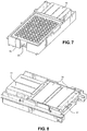
- FIG. 7 illustrates a micro-well plate 38 containing a plurality of wells 42 disposed directly in the holding space 40 ( FIG. 5 ) of the tray 14.
- FIG. 8 illustrates glass slides 36 on the glass slide adapter 32 in the sample tray 14.
- different size micro-well plates 38A, 38B, or 38C may be used to prepare and analyze samples using the digital dispense system 10 described above.
- a sample tray 44 specifically designed to accommodate a well plate adapter 46 may be used.
- the well plate adapter 46 may contain a gate 50 that may be used to restrict the position of the micro-well plate 38A, 38B and 38C in well plate adapter 46 as shown.
- the gate is molded into the well plate adapters 46.
- the gate 50 is adjustable with respect to the well plate adapter 46 so as to accommodate a wide variety and sizes of micro-well plates 38A-38C.
- FIG. 10 is a perspective view of the tray 54 having a registration device 56 for urging the micro-well plate 38 into the predetermined registration position so that the micro-well plate 38 abuts edges 58 and 60 of the tray 54.
- the registration device 56 may be a spring-loaded lever that has a distal end 62 that abuts a chamfer 64 of the micro-well plate 38 in order to urge the micro-well plate 38 toward edges 58 and 60 of the tray 54.
- the registration device 56 may be rotated clockwise in the direction of arrow 66 to load the micro-well plate 38 into the tray 54.
- the registration device 56 is released and a spring (not shown) causes the registration device 56 to rotate in a counter-clockwise direction indicated by arrow 68 so that the distal end 62 of the registration device 56 abuts the chamfer 64 of the micro-well pate 38 thereby urging the micro-well plate 38 in the direction of arrows 70 and 72.
- the registration device 56 enables precise deposition of fluid into the wells 42 of the micro-well plate 38.
- the number of drops required to dispense a given volume of fluid is defined as (volume/drop size). For example, if a drop size is selected as 10 pico-liters, and it is required to dispense 10 micro-liters, then the ejection head and fluid cartridge 12 will have to dispense 10/10 e-6 or 1,000,000 drops. Now that the number of drops is determined for the given volume, the area can be calculated. Most inkjet printers print on a grid that has a specific resolution, for example 600H x 1200V DPI (drops per inch).
- the input data that is created by the foregoing calculations is effectively an image representing both X and Y axes, but also introducing a Z axis that represents volume.
- a 4 th dimension is introduced to track the different channels or fluids.
- an ejection head on the ejection head and fluid cartridge 12 has a length of 0.5 inches and can cover the entire area. This is not always be the case, so an additional variable must be introduced, which is the length of the ejection head. For example, if we continue the example from above, but assume that ejection head has a length of 0.25 inches, this introduces a requirement to move either the ejection head and fluid cartridge 12 over the slide or well plate in the x direction to fill in the area correctly. Furthermore, there may be reasons in certain applications to increase the number of passes beyond what is the minimum required. Some examples could include:
- Variations may be achieved by setting an artificial minimum number of passes for the job. This becomes a multiplier to be used with the required number of passes. So, if the minimum number of passes of 2, then a 50% maximum limit can be set on the number of drops in each pass, which will multiply the total number of passes by 2 overall.
- the foregoing method provides benefits over traditional digital dispense systems which may print the entire volume of fluid into a micro-plate well in a single operation.
- the foregoing method spreads the volume of fluid to be dispensed over multiple dispense head passes and multiple fluid ejectors along a dispense head array of an ejection head. This will minimize the impact of missing or poorly performing fluid ejectors.
- a minimum number of fluid ejectors to use can be specified or calculated.
- test may be improved by controlling the rate at which the fluid is deposited.
- the digital dispense system 10 described herein will enable a user to better control the deposition rate.
- the digital dispense system 10 enables a volume of fluid to be spread consistently over an area/shape that is specified. It also enables a mode to be defined that minimizes variations by distributing ejector head nozzle usage over the entire ejection head. A minimum number of passes of the ejection head and fluid cartridge 12 can be specified along with a maximum volume per pass. If the maximum volume per pass exceeds a defined flow rate, additional passes can be added to the operation mode.
- the dispense system 10 can be scaled to dispense one or more fluids onto a glass slide or micro-well plate.
- the sample tray 14 described above can be use with glass slides to dispense fluids on the glass slides to analyze body fluids such as blood.
- the glass slides with bloods smears may be stained with multiple stains and other fluid types selectively or simultaneously using the digital dispense system 10 according to the disclosure in order to create stained slides for studying cells types in blood samples.
- the use of stains to identify the blood cells has been used for a long time, but the technique for putting stains on slides is very tedious.
- Romanowsky type stains have been used to identify red blood cell (RBC) and white blood cell (WBC) from blood smears on glass slides.
- RBC red blood cell
- WBC white blood cell
- Most laboratories use some form of Romanowsky type stain (e.g. Wright-Giemsa). These stains give excellent results but the method to put the stains on slides is cumbersome.
- the slides with blood smears are dipped in stains for a period of time.
- dipping slides is labor and time intensive.
- the digital dispense system 10 provides an improved technique for creating stained slides for studying cell types in blood samples by depositing precise amounts of fluids in defined locations on the slides.
- stains such as Giemsa stain for May Grunwald and Giemsa stain or any other type of stains and a buffer solution may then be deposited simultaneously or selectively onto the glass slides.
- the digital dispense system 10 provides the flexibility of either jetting one, two or more stains and buffer solutions simultaneously or selectively. The amount of stains used by this method is much less compared to the dipping technique. The use of this technique is not limited to Giemsa and May Grunwald stains. It can be used with any other fluid that meets the requirements of fluid ejection technology. A predetermined volume of each fluid can be deposited onto a sample using the dispense system 10 described above.
Landscapes
- Health & Medical Sciences (AREA)
- Life Sciences & Earth Sciences (AREA)
- Chemical & Material Sciences (AREA)
- Engineering & Computer Science (AREA)
- Pathology (AREA)
- Immunology (AREA)
- Physics & Mathematics (AREA)
- Analytical Chemistry (AREA)
- Biochemistry (AREA)
- General Health & Medical Sciences (AREA)
- General Physics & Mathematics (AREA)
- Molecular Biology (AREA)
- Biomedical Technology (AREA)
- Clinical Laboratory Science (AREA)
- Chemical Kinetics & Catalysis (AREA)
- Ceramic Engineering (AREA)
- Sampling And Sample Adjustment (AREA)
- Automatic Analysis And Handling Materials Therefor (AREA)
Abstract
Description
- This application claims priority to provisional application serial No.
62/788,290, filed January 4, 2019 - The disclosure is directed to analytical instruments and in particular to instruments that are used to dispense fluids for analytical purposes.
- In the medical field, in particular, there is a need for automated sample preparation and analysis. The analysis may be colorimetric analysis or require the staining of samples to better observe the samples under a microscope. Such analysis may include drug sample analysis, blood sample analysis and the like. In the analysis of blood, for example, blood is analyzed to provide a number of different factors that are used to determine the health of an individual. When there are a large number of patients that require blood sample analysis, the procedures may be extremely time consuming. Also, there is a need for accurate preparation of the samples so that the results can be relied on. There are many other situations that require sample analysis in the medical field and in other fields that can benefit from the use of analytical instruments that provide accurate and reproduceable results, such as micro-titration of multiple samples.
- Well plates, slides and other substrates are used for many experiments and laboratory procedures. The process of filling the wells or spotting glass slides is often performed manually or using expensive lab equipment. In some cases, the wells are filled with hand operated pipettes. In other cased, high-end automated devices based on pipette technology are used to fill the well plates. Such automated devices accommodate an open well dispense head only. The open well dispense head is a dispense head where a small amount of fluid must be deposited into an opening in the dispense head before use. The fluid is typically deposited manually using a pipette or similar means. The dispense head is held stationary while moving the microplate in both x and y directions. These high end devices are extremely expensive. Accordingly, there is a need for a digital dispense system that can be used in a wide variety of analytical situations for analysis and digital titration of samples on glass slides and micro-well plates that is much less expensive to purchase and adaptable to different numbers of glass slides and different sizes of micro-well plates.
- In view of the foregoing, an embodiment of the disclosure provides a digital dispense system and method for preparing samples for analysis. The digital dispense system includes a fluid droplet ejection system housed in a housing unit. The fluid droplet ejection system contains a fluid droplet ejection head and fluid cartridge containing one or more fluids to be dispensed. A cartridge translation mechanism is provided for moving the fluid droplet ejection head and fluid cartridge back and forth over a sample holder in an x direction. A sample tray translation mechanism moves a sample tray back and forth beneath the fluid droplet ejection head and fluid cartridge in a direction orthogonal to the x direction.
- In another embodiment there is provided a method for staining glass slides without immersing the slides in a dye. The method includes providing a digital fluid droplet ejection system housed in a housing unit. The fluid droplet ejection system includes a fluid droplet ejection head and fluid cartridge containing one or more fluids to be dispensed. A cartridge translation mechanism is provided for moving the fluid droplet ejection head and fluid cartridge back and forth over a slide holder in an x direction. A sample tray for holding one or more glass slides is also provided. The sample tray includes a sample tray adapter configured to hold the one or more glass slides in the sample tray. A sample tray translation mechanism is provided for moving the sample tray and one or more glass slides back and forth beneath the fluid droplet ejection head and fluid cartridge in a direction orthogonal to the x direction. Fluid is ejected from the fluid droplet ejection head and fluid cartridge in one or more locations on the one or more glass slides.
- A further embodiment provides a method for processing samples in wells of a micro-well plate for analysis. The method includes providing a digital fluid droplet ejection system housed in a housing unit. The fluid droplet ejection system contains a fluid droplet ejection head and fluid cartridge containing one or more fluids to be dispensed. A cartridge translation mechanism is provided for moving the fluid droplet ejection head and fluid cartridge back and forth over a micro-well plate sample tray in an x direction. A sample tray translation mechanism is also provided for moving the sample tray containing the micro-well plate through the fluid droplet ejection device in a y direction orthogonal to the x direction. During the process fluid is ejected from the fluid droplet ejection head and fluid cartridge into one or more wells in the micro-well plate.
- In some embodiments, the sample tray further includes a tray adapter for holding one or more glass slides or a micro-well plate.
- In some embodiments, two or more fluids are ejected on a slide or into wells of a micro-well plate simultaneously. In other embodiments two or more fluids are ejected on a slide or into wells of a micro-well plate sequentially.
- In some embodiments, the tray adapter is a glass slide adapter for holding one or more glass slides. In one embodiment, the glass slide adapter is selected from an adapter configured to hold one glass slide, an adapter configured to hold two glass slides, and an adapter configured to hold three glass slides. In other embodiments, the tray adapter is a micro-well plate adapter for holding a micro-well plate. In still other embodiments the tray adapter is sized for different size micro-well plates.
- In some embodiments, the sample tray further includes a spring-loaded lever for positioning glass slides or a micro-well plate in the sample tray so that the glass slides or micro-well plate are in a predetermined location for fluid droplet ejection. In other embodiments, a distal end of the spring loaded lever abuts a chamfer on one corner of the micro-well plate or a chamfer on one corner of a glass slide adapter.
- While only a small number of slides may be processed at one time in the digital dispense system, each well plate may have 96, 384, or 1536 wells or may have a customized number of wells depending on the application and analysis to be performed. Likewise, analysis may include the use of one, two, or three glass slides at a time. Embodiments of the disclosure provide unique and quite efficient system for handling different numbers of glass slides and different size micro-well plates in a digital dispense system. The system described herein may also be adapted to provide multi-analyte and biofluid dispensing and analysis on a substrate that contains both glass slides and micro-well plates of different sizes for point-of-care monitoring and diagnostic applications at home or in a small clinic.
-
-
FIG. 1 is a perspective view, not to scale, of a digital dispense system according to an embodiment of the disclosure. -
FIG. 2 is an elevational view, not to scale, of a back side of the digital dispense system ofFIG. 1 . -
FIG. 3 is a perspective cutaway view, not to scale, of the digital dispense system ofFIG. 1 . -
FIG. 4 is a schematic view of the digital dispense system ofFIG. 1 showing a sample tray and micro-well plate in a position inside the digital dispense system for fluid deposition onto the micro-well plate. -
FIG. 5 is a perspective view, not to scale, of a tray for holding samples for use with the digital dispense system ofFIG. 1 . -
FIG. 6 is a perspective view, not to scale, of adapters for glass slides and micro-well plates for use with the tray ofFIG. 5 . -
FIG. 7 is a perspective view, not to scale, of the tray ofFIG. 4 holding a well plate adapter and micro-well plate for the digital dispense system ofFIG. 1 . -
FIG. 7 is a perspective view, not to scale, of the tray ofFIG. 4 holding a micro-well plate for the digital dispense system ofFIG. 1 . -
FIG. 8 is a perspective view, not to scale, of the tray ofFIG. 4 holding a glass slide adapter and glass slides for the digital dispense system ofFIG. 1 . -
FIGS. 9A-9C are schematic plan views, not to scale, of a sample tray, and a well plate adapter for holding different sizes of micro-well plates in the sample tray. -
FIG. 10 is a perspective view, not to scale of a micro-well plate in a tray according to another embodiment of the disclosure. -
FIG. 11 is a plan view, not to scale of the micro-well plate in the tray ofFIG. 10 . - With reference to
FIGS. 1-4 there is shown a digital dispensesystem 10 for accurately dispensing an amount of one or more fluids into the wells of a micro-well plate, or in some defined pattern of spots on one or more glass slides (commonly referred to as spotting). Unlike the high-end digital dispense devices, the system10 of the present invention is based on an ejection head andfluid cartridge 12 that moves back and forth in a first direction and asample tray 14 containing the well plate or slides that moves back and forth in a second direction orthogonal to the first direction, as described in more detail below. The discloseddevice 10 can accept open and closed ejection fluid cartridges. Thesample tray 14 is adaptable to standard micro-well plates, customized micro-well plates and glass slides. The ejection head on the ejection head andfluid cartridge 12 may be selected from a wide variety of ejection head devices including, but not limited to, thermal jet ejection heads, bubble jet ejection heads, piezoelectric ejection heads, and the like. - The ejection head and
fluid cartridge 12 is moved back and forth in an x direction by a cartridge movement mechanism 16 (FIG. 3 ) both of which are contained in a rectangular prism-shapedbox 18. Anactivation switch 20 is included on thebox 18 for activating thesystem 10. A rear side 22 of thebox 18 includes anopening 24 for movement of thesample tray 14 through thebox 18 in the second direction orthogonal to the x direction to dispense fluid into the micro-well plate or slides. AUSB port 26 is provided on the rear side 22 of thebox 18 to connect the digital dispensesystem 10 to a computer or a digital display device. Power is provided to thesystem 10 through apower input port 28 on the rear side 22 of thebox 18.FIG. 4 illustrates a view through thebox 18 of the digital dispensesystem 10 showing thesample tray 14 containing a micro-well plate in position within the system for fluid deposition thereto. A sampletray movement mechanism 30 provides movement of thesample tray 14 in a direction through the system that is orthogonal to the movement of the ejection head andfluid cartridge 12. - The
sample tray 14 andadapters sample tray 14 are illustrated inFIGS. 5 and 6 . Theadapters system 10 to deposit fluids on a variety of surfaces. Theadapter 32 is particularly suitable for holding two glass slides 36 as shown, however, an adapter to hold only one glass slide or three glass slides may also be used.Adapter 40 is specifically designed to hold amicro-well plate 38. Bothadapters adapter holding space 40 in thesample tray 14. In some embodiments, as described in more detail below, themicro-well plate 38 is disposed directly in the holdingspace 40 of thetray 14 in the absence of theadapter 34.FIG. 7 illustrates amicro-well plate 38 containing a plurality ofwells 42 disposed directly in the holding space 40 (FIG. 5 ) of thetray 14.FIG. 8 illustrates glass slides 36 on theglass slide adapter 32 in thesample tray 14. - In some embodiments, as illustrated in
FIGS. 9A-9C , different sizemicro-well plates system 10 described above. In order to accommodate various micro-well plate sizes, asample tray 44 specifically designed to accommodate awell plate adapter 46 may be used. Thewell plate adapter 46 may contain agate 50 that may be used to restrict the position of themicro-well plate well plate adapter 46 as shown. In some embodiments, the gate is molded into thewell plate adapters 46. In other embodiments, thegate 50 is adjustable with respect to thewell plate adapter 46 so as to accommodate a wide variety and sizes ofmicro-well plates 38A-38C. - In order for the
system 10 to deposit fluids in the precise well locations on themicro-well plate 38, an embodiment of the disclosure provides a device for urging amicro-well plate 38 or glass-slide adapter 32 into a pre-determined registration position within asample tray 54 is illustrated inFIGS. 10-11 .FIG. 10 is a perspective view of thetray 54 having aregistration device 56 for urging themicro-well plate 38 into the predetermined registration position so that themicro-well plate 38 abuts edges 58 and 60 of thetray 54. Theregistration device 56 may be a spring-loaded lever that has adistal end 62 that abuts achamfer 64 of themicro-well plate 38 in order to urge themicro-well plate 38 towardedges tray 54. Accordingly, theregistration device 56 may be rotated clockwise in the direction ofarrow 66 to load themicro-well plate 38 into thetray 54. Once themicro-well plate 38 is loaded into thetray 54, theregistration device 56 is released and a spring (not shown) causes theregistration device 56 to rotate in a counter-clockwise direction indicated byarrow 68 so that thedistal end 62 of theregistration device 56 abuts thechamfer 64 of themicro-well pate 38 thereby urging themicro-well plate 38 in the direction ofarrows registration device 56 enables precise deposition of fluid into thewells 42 of themicro-well plate 38. - For a given volume of fluid to be deposited on a
glass slide 36 or intowells 42 of amicro-well plate 38 using thesystem 10 described above, the number of drops required to dispense a given volume of fluid is defined as (volume/drop size). For example, if a drop size is selected as 10 pico-liters, and it is required to dispense 10 micro-liters, then the ejection head andfluid cartridge 12 will have to dispense 10/10e-6 or 1,000,000 drops. Now that the number of drops is determined for the given volume, the area can be calculated. Most inkjet printers print on a grid that has a specific resolution, for example 600H x 1200V DPI (drops per inch). If the target area is a square that is 0.5 inches x 0.5 inches, then the maximum number of drops that can be dispensed in that area with one pass of the ejection head andfluid cartridge 14 can be calculated as follows:


fluid cartridge 12 will need to make 5 full passes, and then a 'remainder' pass that is not entirely full to dispense the volume of fluid calculated over a given area. Each of the passes will spread the drops consistently over the area. - The input data that is created by the foregoing calculations is effectively an image representing both X and Y axes, but also introducing a Z axis that represents volume. In addition, when dispensing more than 1 channel or fluid at once, a 4th dimension is introduced to track the different channels or fluids.
- The foregoing assumes an ejection head on the ejection head and
fluid cartridge 12 has a length of 0.5 inches and can cover the entire area. This is not always be the case, so an additional variable must be introduced, which is the length of the ejection head. For example, if we continue the example from above, but assume that ejection head has a length of 0.25 inches, this introduces a requirement to move either the ejection head andfluid cartridge 12 over the slide or well plate in the x direction to fill in the area correctly. Furthermore, there may be reasons in certain applications to increase the number of passes beyond what is the minimum required. Some examples could include: - To improve some aspect of the output (coverage, uniformity, etc.)
- To artificially limit the maximum volume per pass for experimental reasons.
- Variations may be achieved by setting an artificial minimum number of passes for the job. This becomes a multiplier to be used with the required number of passes. So, if the minimum number of passes of 2, then a 50% maximum limit can be set on the number of drops in each pass, which will multiply the total number of passes by 2 overall.
- The foregoing method provides benefits over traditional digital dispense systems which may print the entire volume of fluid into a micro-plate well in a single operation. The foregoing method spreads the volume of fluid to be dispensed over multiple dispense head passes and multiple fluid ejectors along a dispense head array of an ejection head. This will minimize the impact of missing or poorly performing fluid ejectors. Depending on the desired dispense accuracy and probability of ejectors not functioning correctly, a minimum number of fluid ejectors to use can be specified or calculated.
- In fields such as hematology it may be desirable to deposit or print multiple stains or buffers over a defined area of a substrate such as a glass slide. When printing layers of fluid, the test may be improved by controlling the rate at which the fluid is deposited. The digital dispense
system 10 described herein will enable a user to better control the deposition rate. - In some embodiments, the digital dispense
system 10 according to the disclosure enables a volume of fluid to be spread consistently over an area/shape that is specified. It also enables a mode to be defined that minimizes variations by distributing ejector head nozzle usage over the entire ejection head. A minimum number of passes of the ejection head andfluid cartridge 12 can be specified along with a maximum volume per pass. If the maximum volume per pass exceeds a defined flow rate, additional passes can be added to the operation mode. The dispensesystem 10 can be scaled to dispense one or more fluids onto a glass slide or micro-well plate. - In some embodiments, the
sample tray 14 described above can be use with glass slides to dispense fluids on the glass slides to analyze body fluids such as blood. The glass slides with bloods smears may be stained with multiple stains and other fluid types selectively or simultaneously using the digital dispensesystem 10 according to the disclosure in order to create stained slides for studying cells types in blood samples. The use of stains to identify the blood cells has been used for a long time, but the technique for putting stains on slides is very tedious. - Romanowsky type stains have been used to identify red blood cell (RBC) and white blood cell (WBC) from blood smears on glass slides. Most laboratories use some form of Romanowsky type stain (e.g. Wright-Giemsa). These stains give excellent results but the method to put the stains on slides is cumbersome. In the conventional method, the slides with blood smears are dipped in stains for a period of time. However, dipping slides is labor and time intensive. As described above, the digital dispense
system 10 provides an improved technique for creating stained slides for studying cell types in blood samples by depositing precise amounts of fluids in defined locations on the slides. - In some embodiments, stains such as Giemsa stain for May Grunwald and Giemsa stain or any other type of stains and a buffer solution may then be deposited simultaneously or selectively onto the glass slides. The digital dispense
system 10 provides the flexibility of either jetting one, two or more stains and buffer solutions simultaneously or selectively. The amount of stains used by this method is much less compared to the dipping technique. The use of this technique is not limited to Giemsa and May Grunwald stains. It can be used with any other fluid that meets the requirements of fluid ejection technology. A predetermined volume of each fluid can be deposited onto a sample using the dispensesystem 10 described above. - It is noted that, as used in this specification and the appended claims, the singular forms "a," "an," and "the," include plural referents unless expressly and unequivocally limited to one referent. As used herein, the term "include" and its grammatical variants are intended to be non-limiting, such that recitation of items in a list is not to the exclusion of other like items that can be substituted or added to the listed items
- For the purposes of this specification and appended claims, unless otherwise indicated, all numbers expressing quantities, percentages or proportions, and other numerical values used in the specification and claims, are to be understood as being modified in all instances by the term "about." Accordingly, unless indicated to the contrary, the numerical parameters set forth in the following specification and attached claims are approximations that can vary depending upon the desired properties sought to be obtained by the present disclosure. At the very least, and not as an attempt to limit the application of the doctrine of equivalents to the scope of the claims, each numerical parameter should at least be construed in light of the number of reported significant digits and by applying ordinary rounding techniques.
- While particular embodiments have been described, alternatives, modifications, variations, improvements, and substantial equivalents that are or can be presently unforeseen can arise to applicants or others skilled in the art. Accordingly, the appended claims as filed and as they can be amended are intended to embrace all such alternatives, modifications variations, improvements, and substantial equivalents.
Claims (14)
- A digital dispense system for preparing samples for analysis, comprising a fluid droplet ejection system housed in a housing unit, the fluid droplet ejection system including:a fluid droplet ejection head and fluid cartridge containing one or more fluids to be dispensed,a cartridge translation mechanism for moving the fluid droplet ejection head and fluid cartridge back and forth over a sample holder in an x direction; anda sample tray translation mechanism for moving a sample tray back and forth beneath the fluid droplet ejection head and fluid cartridge in a y direction orthogonal to the x direction.
- The digital dispense system of claim 1, wherein sample tray further comprises a glass slide adapter for holding one or more glass slides.
- The digital dispense system of claim 1, wherein the sample tray further comprises a micro-well plate adapter for holding a micro-well plate.
- The digital dispense system of claim 3, wherein the micro-well plate adapter is sized for different size micro-well plates.
- The digital dispense system of claim 2, wherein the glass slide adapter is selected from the group consisting of an adapter configured to hold one glass slide, an adapter configured to hold two glass slides, and an adapter configured to hold three glass slides.
- The digital dispense system of claim 1, wherein the sample tray further comprises a biasing means to bias the glass slides or micro-well plate in the sample tray to a predetermined location.
- The digital dispense system of claim 6, wherein the biasing means comprises a spring-loaded lever for positioning glass slides or a micro-well plate in the sample tray so that the glass slides or micro-well plate are in a predetermined location for fluid droplet ejection.
- The digital dispense system of claim 7, wherein a distal end of the spring loaded lever abuts a chamfer on one corner of the micro-well plate or a chamfer on one corner of a glass slide adapter.
- A method for staining glass slides without immersing the slides in a dye, comprising:providing a digital fluid droplet ejection system housed in a housing unit, the fluid droplet ejection system including:a fluid droplet ejection head and fluid cartridge containing one or more fluids to be dispensed,a cartridge translation mechanism for moving the fluid droplet ejection head and fluid cartridge back and forth over a slide holder in an x direction,a sample tray for holding one or more glass slides;a sample tray adapter configured to hold one or more glass slides in the sample tray, anda sample tray translation mechanism for moving the sample tray and one or more glass slides back and forth beneath the fluid droplet ejection head and fluid cartridge in a y direction orthogonal to the x direction;ejecting fluid from the fluid droplet ejection head and fluid cartridge in one or more locations on the one or more glass slides.
- The method of claim 9, further comprising ejecting two or more fluids onto the slides simultaneously.
- The method of claim 9, further comprising ejecting two or more fluids onto the slides sequentially.
- A method for processing samples in wells of a micro-well plate for analysis, comprising:providing a digital fluid droplet ejection system housed in a housing unit, the fluid droplet ejection system including:a fluid droplet ejection head and fluid cartridge containing one or more fluids to be dispensed,a cartridge translation mechanism for moving the fluid droplet ejection head and fluid cartridge back and forth over a micro-well plate sample tray in an x direction,a sample tray translation mechanism for moving the sample tray containing the micro-well plate through the fluid droplet ejection device in a y direction orthogonal to the x direction; andejecting fluid from the fluid droplet ejection head and fluid cartridge into one or more wells in the micro-well plate.
- The method of claim 12, further comprising ejecting two or more fluids into wells of the micro-well plate simultaneously.
- The method of claim 12, further comprising ejecting two or more fluids into wells of the micro-well plate sequentially.
Applications Claiming Priority (2)
| Application Number | Priority Date | Filing Date | Title |
|---|---|---|---|
| US201962788290P | 2019-01-04 | 2019-01-04 | |
| US16/558,141 US11474007B2 (en) | 2019-01-04 | 2019-09-01 | Digital dispense system |
Publications (2)
| Publication Number | Publication Date |
|---|---|
| EP3677918A1 true EP3677918A1 (en) | 2020-07-08 |
| EP3677918B1 EP3677918B1 (en) | 2023-10-04 |
Family
ID=69055692
Family Applications (1)
| Application Number | Title | Priority Date | Filing Date |
|---|---|---|---|
| EP19219747.3A Active EP3677918B1 (en) | 2019-01-04 | 2019-12-27 | Digital dispense system |
Country Status (4)
| Country | Link |
|---|---|
| US (2) | US11474007B2 (en) |
| EP (1) | EP3677918B1 (en) |
| JP (1) | JP7409081B2 (en) |
| CN (1) | CN111413180A (en) |
Families Citing this family (3)
| Publication number | Priority date | Publication date | Assignee | Title |
|---|---|---|---|---|
| US11169073B2 (en) * | 2019-05-24 | 2021-11-09 | Essen Instruments, Inc. | Apparatus for supplying reagents to a flow cytometry system |
| JP2022120493A (en) | 2021-02-05 | 2022-08-18 | 船井電機株式会社 | Static elimination device and droplet ejection system |
| US12669455B2 (en) * | 2024-03-21 | 2026-06-30 | Brady Worldwide, Inc. | Method and apparatus for determining water content of hygroscopic fluids |
Citations (3)
| Publication number | Priority date | Publication date | Assignee | Title |
|---|---|---|---|---|
| US20030026737A1 (en) * | 2001-08-01 | 2003-02-06 | Takashi Inoue | Liquid ejection device and sample carrier preparation apparatus |
| US20060153621A1 (en) * | 2002-09-27 | 2006-07-13 | Manning Howard J | Method and apparatus for substrate handling and printing |
| US20140112839A1 (en) * | 2012-10-24 | 2014-04-24 | Accel Biotech, Inc. | Multi-function dispense head |
Family Cites Families (71)
| Publication number | Priority date | Publication date | Assignee | Title |
|---|---|---|---|---|
| US3568735A (en) | 1968-06-26 | 1971-03-09 | Cooke Eng Co | Laboratory microtitration dispensing apparatus |
| DD226092A1 (en) * | 1984-04-24 | 1985-08-14 | Zeiss Jena Veb Carl | OBJEK HOLDER FOR MICROSCOPES |
| US6800452B1 (en) | 1994-08-08 | 2004-10-05 | Science Applications International Corporation | Automated methods for simultaneously performing a plurality of signal-based assays |
| US5958342A (en) | 1996-05-17 | 1999-09-28 | Incyte Pharmaceuticals, Inc. | Jet droplet device |
| CA2702219C (en) | 1996-11-06 | 2013-01-08 | Sequenom, Inc. | High density immobilization of nucleic acids |
| US5985214A (en) | 1997-05-16 | 1999-11-16 | Aurora Biosciences Corporation | Systems and methods for rapidly identifying useful chemicals in liquid samples |
| JP3856171B2 (en) * | 1997-10-09 | 2006-12-13 | 株式会社ニコン | Microscope stage with specimen holder |
| US7470547B2 (en) * | 2003-07-31 | 2008-12-30 | Biodot, Inc. | Methods and systems for dispensing sub-microfluidic drops |
| WO1999049295A1 (en) * | 1998-03-24 | 1999-09-30 | Biogenex Laboratories | Automated staining apparatus |
| US7199809B1 (en) | 1998-10-19 | 2007-04-03 | Symyx Technologies, Inc. | Graphic design of combinatorial material libraries |
| US6627157B1 (en) | 1999-03-04 | 2003-09-30 | Ut-Battelle, Llc | Dual manifold system and method for fluid transfer |
| US6604806B1 (en) | 1999-10-20 | 2003-08-12 | Canon Kabushiki Kaisha | High resolution printing |
| EP1111391B1 (en) * | 1999-12-21 | 2006-07-26 | Tecan Trading AG | Clamping device for holding and aligning an item such as a microtitration plate, and method for its use |
| CA2311622A1 (en) | 2000-06-15 | 2001-12-15 | Moussa Hoummady | Sub-nanoliter liquid drop dispensing system and method therefor |
| EP1174702A1 (en) * | 2000-07-20 | 2002-01-23 | Medic SRL | Automatic equipment for processing microscope slides for colouring biological specimens |
| US7135146B2 (en) | 2000-10-11 | 2006-11-14 | Innovadyne Technologies, Inc. | Universal non-contact dispense peripheral apparatus and method for a primary liquid handling device |
| JP3870020B2 (en) | 2000-10-24 | 2007-01-17 | キヤノン株式会社 | Inkjet printing apparatus and ejection data creation method |
| US7024281B1 (en) | 2000-12-11 | 2006-04-04 | Callper Life Sciences, Inc. | Software for the controlled sampling of arrayed materials |
| US6982063B2 (en) | 2001-05-25 | 2006-01-03 | Matrix Technologies Corp | Automated pipetting system |
| US20040231594A1 (en) | 2001-06-01 | 2004-11-25 | Edwards Charles O. | Microdeposition apparatus |
| US6864480B2 (en) | 2001-12-19 | 2005-03-08 | Sau Lan Tang Staats | Interface members and holders for microfluidic array devices |
| US7568779B2 (en) | 2003-02-10 | 2009-08-04 | Canon Kabushiki Kaisha | Liquid applicator and liquid supply method to be used in liquid applicator |
| EP2489433A1 (en) * | 2003-09-09 | 2012-08-22 | BioGenex Laboratories | Sample processing system |
| JP3695661B2 (en) | 2003-10-02 | 2005-09-14 | セイコーエプソン株式会社 | Recording device |
| CA2543091C (en) * | 2003-10-24 | 2013-09-03 | John Austin | Apparatus and method for dispensing fluid, semi-solid and solid samples |
| JP3950972B2 (en) | 2003-11-14 | 2007-08-01 | 国立大学法人名古屋大学 | Bioluminescence measuring device for biological samples |
| US7640787B2 (en) | 2004-02-06 | 2010-01-05 | Seyonic S.A. | Pipette verification device and pipette |
| US7534395B2 (en) | 2004-04-27 | 2009-05-19 | Beckman Coulter, Inc. | Hysteresis compensation system |
| EP1789195B1 (en) | 2004-08-26 | 2010-10-27 | Life Technologies Corporation | Electrowetting dispensing devices and related methods |
| CN100374301C (en) | 2004-12-31 | 2008-03-12 | 财团法人工业技术研究院 | Print data conversion method and apparatus |
| EP1866653A4 (en) | 2005-03-07 | 2009-08-26 | Novx Systems Inc | AUTOMATED ANALYZER |
| EP1882189A2 (en) | 2005-04-20 | 2008-01-30 | Fluidigm Corporation | Analysis engine and database for manipulating parameters for fluidic systems on a chip |
| CN101863163B (en) * | 2005-04-25 | 2012-08-08 | 株式会社爱发科 | Printable substrate and nozzle alignment system |
| EP1949070A4 (en) | 2005-11-01 | 2009-11-18 | Symyx Technologies Inc | Liquid dispensing for high-throughput experimentation |
| WO2007063459A1 (en) | 2005-11-29 | 2007-06-07 | Koninklijke Philips Electronics N.V. | Ink jet device and method for producing a biological assay substrate by releasing a plurality of substances onto the substrate |
| US7998708B2 (en) | 2006-03-24 | 2011-08-16 | Handylab, Inc. | Microfluidic system for amplifying and detecting polynucleotides in parallel |
| JP2008151594A (en) | 2006-12-15 | 2008-07-03 | Anritsu Sanki System Co Ltd | Analyzer |
| EP2149081B1 (en) | 2007-04-17 | 2019-06-12 | Luminex Corporation | Graphical user interface for analysis and comparison of location-specific multiparameter data sets |
| US7909424B2 (en) | 2007-07-31 | 2011-03-22 | Hewlett-Packard Development Company, L.P. | Method and system for dispensing liquid |
| US8658110B2 (en) | 2007-08-13 | 2014-02-25 | Hewlett-Packard Development Company, L.P. | Fluid delivery system |
| CN102316988B (en) | 2007-09-29 | 2014-02-19 | Ei频谱有限责任公司 | Instrumented pipette tip |
| US8222048B2 (en) | 2007-11-05 | 2012-07-17 | Abbott Laboratories | Automated analyzer for clinical laboratory |
| TWI537203B (en) * | 2007-11-27 | 2016-06-11 | 惠普研發公司 | Preparing a titration series |
| WO2009076572A2 (en) | 2007-12-12 | 2009-06-18 | 3M Innovative Properties Company | Methods of making an article and articles |
| US8808625B2 (en) * | 2008-01-11 | 2014-08-19 | National Institute Of Advanced Industrial Science And Technology | Dispensing apparatus and a dispensing method |
| WO2009094648A2 (en) * | 2008-01-25 | 2009-07-30 | Luminex Corporation | Solenoid actuator |
| CN102077095B (en) | 2008-04-24 | 2014-12-10 | 泰肯贸易股份公司 | Direct pipetting in computer-controlled liquid handling workstations |
| WO2010044765A1 (en) | 2008-10-15 | 2010-04-22 | Hewlett-Packard Development Company, L. P. | Method of detecting drops |
| US8201913B2 (en) | 2009-04-20 | 2012-06-19 | Hewlett-Packard Development Company, L.P. | Drop detector |
| US8715574B2 (en) | 2009-06-19 | 2014-05-06 | Abbott Laboratories | System for managing inventory of bulk liquids |
| JP4831215B2 (en) | 2009-07-06 | 2011-12-07 | ブラザー工業株式会社 | Image data processing apparatus and liquid ejection apparatus |
| FR2957672B1 (en) * | 2010-03-22 | 2013-03-15 | Novacyt | AUTOMATIC METHOD AND AUTOMATE FOR PREPARING AND ANALYZING A PLURALITY OF CELLULAR SUSPENSIONS |
| CN110220876B (en) * | 2011-01-10 | 2022-04-26 | 伊鲁米那股份有限公司 | Method for imaging a sample for biological or chemical analysis |
| JP5189664B2 (en) | 2011-03-07 | 2013-04-24 | 富士フイルム株式会社 | Image processing apparatus and method, and image forming apparatus |
| JP5866905B2 (en) | 2011-09-16 | 2016-02-24 | ブラザー工業株式会社 | Control device for causing printing execution unit to execute printing |
| US8883488B2 (en) | 2011-11-15 | 2014-11-11 | Tuskegee University | Detection of food threat agents and food-borne pathogens |
| EP2780722B1 (en) * | 2011-11-16 | 2020-06-24 | Leica Biosystems Melbourne Pty Ltd | An automated system and method of treating tissue samples on slides |
| JP2013137635A (en) | 2011-12-28 | 2013-07-11 | Dainippon Screen Mfg Co Ltd | Picture display unit and picture display method |
| KR20200115664A (en) | 2012-12-27 | 2020-10-07 | 카티바, 인크. | Techniques for print ink volume control to deposit fluids within precise tolerances |
| US9623409B2 (en) | 2013-03-11 | 2017-04-18 | Cue Inc. | Cartridges, kits, and methods for enhanced mixing for detection and quantification of analytes |
| CN113789372B (en) | 2013-08-08 | 2025-02-25 | 伊鲁米那股份有限公司 | Fluidics system for reagent delivery to the flow cell |
| JP6171949B2 (en) | 2014-01-24 | 2017-08-02 | ブラザー工業株式会社 | Liquid discharge head |
| EP4215898A1 (en) | 2015-04-20 | 2023-07-26 | Ventana Medical Systems, Inc. | Inkjet deposition of reagents for histological samples |
| MY188878A (en) | 2015-11-04 | 2022-01-12 | Nitto Denko Corp | Apparatus and system for biofluid sample dispensing and/or assay |
| US10184104B2 (en) * | 2015-11-19 | 2019-01-22 | Alexander Lee Lianides | Automated system for cultivating transgenic C. elegans |
| CN116046500A (en) | 2016-04-28 | 2023-05-02 | 希森美康株式会社 | Sample Applicator |
| WO2018050889A2 (en) | 2016-09-19 | 2018-03-22 | Project Management Limited | An autonomous sampling system |
| US10639916B2 (en) | 2017-03-21 | 2020-05-05 | Ricoh Company, Ltd. | Conveyance device, conveyance system, and head unit position adjusting method |
| JP2018163017A (en) | 2017-03-24 | 2018-10-18 | 東芝テック株式会社 | Droplet dispensing device |
| CN108106911B (en) * | 2017-12-29 | 2024-05-17 | 山东仕达思生物产业有限公司 | Full-automatic slide glass smear dyeing machine |
| US12270820B2 (en) | 2018-06-04 | 2025-04-08 | Hewlett-Packard Development Company, L.P. | Ejection subassembly pitches to match nanowell spacing |
-
2019
- 2019-09-01 US US16/558,141 patent/US11474007B2/en active Active
- 2019-12-27 EP EP19219747.3A patent/EP3677918B1/en active Active
- 2019-12-27 JP JP2019238094A patent/JP7409081B2/en active Active
-
2020
- 2020-01-02 CN CN202010000851.1A patent/CN111413180A/en active Pending
-
2022
- 2022-08-17 US US17/820,370 patent/US11933704B2/en active Active
Patent Citations (3)
| Publication number | Priority date | Publication date | Assignee | Title |
|---|---|---|---|---|
| US20030026737A1 (en) * | 2001-08-01 | 2003-02-06 | Takashi Inoue | Liquid ejection device and sample carrier preparation apparatus |
| US20060153621A1 (en) * | 2002-09-27 | 2006-07-13 | Manning Howard J | Method and apparatus for substrate handling and printing |
| US20140112839A1 (en) * | 2012-10-24 | 2014-04-24 | Accel Biotech, Inc. | Multi-function dispense head |
Also Published As
| Publication number | Publication date |
|---|---|
| US20200217763A1 (en) | 2020-07-09 |
| JP7409081B2 (en) | 2024-01-09 |
| US11474007B2 (en) | 2022-10-18 |
| US11933704B2 (en) | 2024-03-19 |
| JP2020122781A (en) | 2020-08-13 |
| US20220397496A1 (en) | 2022-12-15 |
| EP3677918B1 (en) | 2023-10-04 |
| CN111413180A (en) | 2020-07-14 |
Similar Documents
| Publication | Publication Date | Title |
|---|---|---|
| US11933704B2 (en) | Digital dispense system | |
| EP1470427B1 (en) | Low volume, non-contact liquid dispensing method | |
| CA2543091C (en) | Apparatus and method for dispensing fluid, semi-solid and solid samples | |
| US4985206A (en) | Tissue processing apparatus | |
| US11768215B2 (en) | Digital dispense system cartridge | |
| US8449836B2 (en) | Fixtures for use in parallel processing bio-chips | |
| US20210278322A1 (en) | Digital Dispense System | |
| US20140017148A1 (en) | Systems and Methods for Transfer of Liquid Samples | |
| EP3824265B1 (en) | Automated staining system | |
| WO2020016126A2 (en) | Automated slide processing systems, consumable stainer units, and related technologies | |
| USRE50886E1 (en) | Multi-array ejection head and method of use | |
| JP7724381B2 (en) | Dispensing device and genetic testing device equipped with same | |
| EP4249122A1 (en) | Dispense modes for multi-mode capable device | |
| EP3862093A1 (en) | Maintenance reservoir | |
| LU502046B1 (en) | Method for determining a function for determining a volume of liquid to be dispensed | |
| LU501825B1 (en) | Method for setting a volume of liquid to be dispensed by using a function | |
| LU502213B1 (en) | Method for Determining a Volume of Liquid dispensed from a Receptacle | |
| LU501474B1 (en) | Method for determining a volume of liquid arranged in a receptacle | |
| LU501476B1 (en) | Method for determining a function for determining a volume of liquid to be dispensed | |
| LU501823B1 (en) | Method for determining a function for determining a volume of liquid to be dispensed | |
| US12337312B2 (en) | Microfluidic dispensers for limiting dilution | |
| LU501663B1 (en) | Method for determining a function for determining a volume of liquid to be dispensed | |
| US11366125B2 (en) | Substrate conveyance systems |
Legal Events
| Date | Code | Title | Description |
|---|---|---|---|
| PUAI | Public reference made under article 153(3) epc to a published international application that has entered the european phase |
Free format text: ORIGINAL CODE: 0009012 |
|
| STAA | Information on the status of an ep patent application or granted ep patent |
Free format text: STATUS: THE APPLICATION HAS BEEN PUBLISHED |
|
| AK | Designated contracting states |
Kind code of ref document: A1 Designated state(s): AL AT BE BG CH CY CZ DE DK EE ES FI FR GB GR HR HU IE IS IT LI LT LU LV MC MK MT NL NO PL PT RO RS SE SI SK SM TR |
|
| AX | Request for extension of the european patent |
Extension state: BA ME |
|
| STAA | Information on the status of an ep patent application or granted ep patent |
Free format text: STATUS: REQUEST FOR EXAMINATION WAS MADE |
|
| 17P | Request for examination filed |
Effective date: 20201222 |
|
| RBV | Designated contracting states (corrected) |
Designated state(s): AL AT BE BG CH CY CZ DE DK EE ES FI FR GB GR HR HU IE IS IT LI LT LU LV MC MK MT NL NO PL PT RO RS SE SI SK SM TR |
|
| STAA | Information on the status of an ep patent application or granted ep patent |
Free format text: STATUS: EXAMINATION IS IN PROGRESS |
|
| 17Q | First examination report despatched |
Effective date: 20220901 |
|
| GRAP | Despatch of communication of intention to grant a patent |
Free format text: ORIGINAL CODE: EPIDOSNIGR1 |
|
| STAA | Information on the status of an ep patent application or granted ep patent |
Free format text: STATUS: GRANT OF PATENT IS INTENDED |
|
| INTG | Intention to grant announced |
Effective date: 20230706 |
|
| GRAS | Grant fee paid |
Free format text: ORIGINAL CODE: EPIDOSNIGR3 |
|
| GRAA | (expected) grant |
Free format text: ORIGINAL CODE: 0009210 |
|
| STAA | Information on the status of an ep patent application or granted ep patent |
Free format text: STATUS: THE PATENT HAS BEEN GRANTED |
|
| AK | Designated contracting states |
Kind code of ref document: B1 Designated state(s): AL AT BE BG CH CY CZ DE DK EE ES FI FR GB GR HR HU IE IS IT LI LT LU LV MC MK MT NL NO PL PT RO RS SE SI SK SM TR |
|
| REG | Reference to a national code |
Ref country code: GB Ref legal event code: FG4D |
|
| REG | Reference to a national code |
Ref country code: CH Ref legal event code: EP |
|
| REG | Reference to a national code |
Ref country code: IE Ref legal event code: FG4D |
|
| REG | Reference to a national code |
Ref country code: DE Ref legal event code: R096 Ref document number: 602019038568 Country of ref document: DE |
|
| REG | Reference to a national code |
Ref country code: LT Ref legal event code: MG9D |
|
| REG | Reference to a national code |
Ref country code: NL Ref legal event code: MP Effective date: 20231004 |
|
| REG | Reference to a national code |
Ref country code: AT Ref legal event code: MK05 Ref document number: 1618243 Country of ref document: AT Kind code of ref document: T Effective date: 20231004 |
|
| PG25 | Lapsed in a contracting state [announced via postgrant information from national office to epo] |
Ref country code: NL Free format text: LAPSE BECAUSE OF FAILURE TO SUBMIT A TRANSLATION OF THE DESCRIPTION OR TO PAY THE FEE WITHIN THE PRESCRIBED TIME-LIMIT Effective date: 20231004 |
|
| PG25 | Lapsed in a contracting state [announced via postgrant information from national office to epo] |
Ref country code: GR Free format text: LAPSE BECAUSE OF FAILURE TO SUBMIT A TRANSLATION OF THE DESCRIPTION OR TO PAY THE FEE WITHIN THE PRESCRIBED TIME-LIMIT Effective date: 20240105 |
|
| PG25 | Lapsed in a contracting state [announced via postgrant information from national office to epo] |
Ref country code: IS Free format text: LAPSE BECAUSE OF FAILURE TO SUBMIT A TRANSLATION OF THE DESCRIPTION OR TO PAY THE FEE WITHIN THE PRESCRIBED TIME-LIMIT Effective date: 20240204 |
|
| PG25 | Lapsed in a contracting state [announced via postgrant information from national office to epo] |
Ref country code: LT Free format text: LAPSE BECAUSE OF FAILURE TO SUBMIT A TRANSLATION OF THE DESCRIPTION OR TO PAY THE FEE WITHIN THE PRESCRIBED TIME-LIMIT Effective date: 20231004 |
|
| PG25 | Lapsed in a contracting state [announced via postgrant information from national office to epo] |
Ref country code: AT Free format text: LAPSE BECAUSE OF FAILURE TO SUBMIT A TRANSLATION OF THE DESCRIPTION OR TO PAY THE FEE WITHIN THE PRESCRIBED TIME-LIMIT Effective date: 20231004 |
|
| PG25 | Lapsed in a contracting state [announced via postgrant information from national office to epo] |
Ref country code: ES Free format text: LAPSE BECAUSE OF FAILURE TO SUBMIT A TRANSLATION OF THE DESCRIPTION OR TO PAY THE FEE WITHIN THE PRESCRIBED TIME-LIMIT Effective date: 20231004 |
|
| PG25 | Lapsed in a contracting state [announced via postgrant information from national office to epo] |
Ref country code: LT Free format text: LAPSE BECAUSE OF FAILURE TO SUBMIT A TRANSLATION OF THE DESCRIPTION OR TO PAY THE FEE WITHIN THE PRESCRIBED TIME-LIMIT Effective date: 20231004 Ref country code: IS Free format text: LAPSE BECAUSE OF FAILURE TO SUBMIT A TRANSLATION OF THE DESCRIPTION OR TO PAY THE FEE WITHIN THE PRESCRIBED TIME-LIMIT Effective date: 20240204 Ref country code: GR Free format text: LAPSE BECAUSE OF FAILURE TO SUBMIT A TRANSLATION OF THE DESCRIPTION OR TO PAY THE FEE WITHIN THE PRESCRIBED TIME-LIMIT Effective date: 20240105 Ref country code: ES Free format text: LAPSE BECAUSE OF FAILURE TO SUBMIT A TRANSLATION OF THE DESCRIPTION OR TO PAY THE FEE WITHIN THE PRESCRIBED TIME-LIMIT Effective date: 20231004 Ref country code: BG Free format text: LAPSE BECAUSE OF FAILURE TO SUBMIT A TRANSLATION OF THE DESCRIPTION OR TO PAY THE FEE WITHIN THE PRESCRIBED TIME-LIMIT Effective date: 20240104 Ref country code: AT Free format text: LAPSE BECAUSE OF FAILURE TO SUBMIT A TRANSLATION OF THE DESCRIPTION OR TO PAY THE FEE WITHIN THE PRESCRIBED TIME-LIMIT Effective date: 20231004 Ref country code: PT Free format text: LAPSE BECAUSE OF FAILURE TO SUBMIT A TRANSLATION OF THE DESCRIPTION OR TO PAY THE FEE WITHIN THE PRESCRIBED TIME-LIMIT Effective date: 20240205 |
|
| PG25 | Lapsed in a contracting state [announced via postgrant information from national office to epo] |
Ref country code: SE Free format text: LAPSE BECAUSE OF FAILURE TO SUBMIT A TRANSLATION OF THE DESCRIPTION OR TO PAY THE FEE WITHIN THE PRESCRIBED TIME-LIMIT Effective date: 20231004 Ref country code: RS Free format text: LAPSE BECAUSE OF FAILURE TO SUBMIT A TRANSLATION OF THE DESCRIPTION OR TO PAY THE FEE WITHIN THE PRESCRIBED TIME-LIMIT Effective date: 20231004 Ref country code: PL Free format text: LAPSE BECAUSE OF FAILURE TO SUBMIT A TRANSLATION OF THE DESCRIPTION OR TO PAY THE FEE WITHIN THE PRESCRIBED TIME-LIMIT Effective date: 20231004 Ref country code: NO Free format text: LAPSE BECAUSE OF FAILURE TO SUBMIT A TRANSLATION OF THE DESCRIPTION OR TO PAY THE FEE WITHIN THE PRESCRIBED TIME-LIMIT Effective date: 20240104 Ref country code: LV Free format text: LAPSE BECAUSE OF FAILURE TO SUBMIT A TRANSLATION OF THE DESCRIPTION OR TO PAY THE FEE WITHIN THE PRESCRIBED TIME-LIMIT Effective date: 20231004 Ref country code: HR Free format text: LAPSE BECAUSE OF FAILURE TO SUBMIT A TRANSLATION OF THE DESCRIPTION OR TO PAY THE FEE WITHIN THE PRESCRIBED TIME-LIMIT Effective date: 20231004 |
|
| REG | Reference to a national code |
Ref country code: DE Ref legal event code: R097 Ref document number: 602019038568 Country of ref document: DE |
|
| PG25 | Lapsed in a contracting state [announced via postgrant information from national office to epo] |
Ref country code: DK Free format text: LAPSE BECAUSE OF FAILURE TO SUBMIT A TRANSLATION OF THE DESCRIPTION OR TO PAY THE FEE WITHIN THE PRESCRIBED TIME-LIMIT Effective date: 20231004 |
|
| PG25 | Lapsed in a contracting state [announced via postgrant information from national office to epo] |
Ref country code: CZ Free format text: LAPSE BECAUSE OF FAILURE TO SUBMIT A TRANSLATION OF THE DESCRIPTION OR TO PAY THE FEE WITHIN THE PRESCRIBED TIME-LIMIT Effective date: 20231004 |
|
| PG25 | Lapsed in a contracting state [announced via postgrant information from national office to epo] |
Ref country code: SK Free format text: LAPSE BECAUSE OF FAILURE TO SUBMIT A TRANSLATION OF THE DESCRIPTION OR TO PAY THE FEE WITHIN THE PRESCRIBED TIME-LIMIT Effective date: 20231004 |
|
| PG25 | Lapsed in a contracting state [announced via postgrant information from national office to epo] |
Ref country code: SM Free format text: LAPSE BECAUSE OF FAILURE TO SUBMIT A TRANSLATION OF THE DESCRIPTION OR TO PAY THE FEE WITHIN THE PRESCRIBED TIME-LIMIT Effective date: 20231004 Ref country code: SK Free format text: LAPSE BECAUSE OF FAILURE TO SUBMIT A TRANSLATION OF THE DESCRIPTION OR TO PAY THE FEE WITHIN THE PRESCRIBED TIME-LIMIT Effective date: 20231004 Ref country code: RO Free format text: LAPSE BECAUSE OF FAILURE TO SUBMIT A TRANSLATION OF THE DESCRIPTION OR TO PAY THE FEE WITHIN THE PRESCRIBED TIME-LIMIT Effective date: 20231004 Ref country code: IT Free format text: LAPSE BECAUSE OF FAILURE TO SUBMIT A TRANSLATION OF THE DESCRIPTION OR TO PAY THE FEE WITHIN THE PRESCRIBED TIME-LIMIT Effective date: 20231004 Ref country code: EE Free format text: LAPSE BECAUSE OF FAILURE TO SUBMIT A TRANSLATION OF THE DESCRIPTION OR TO PAY THE FEE WITHIN THE PRESCRIBED TIME-LIMIT Effective date: 20231004 Ref country code: DK Free format text: LAPSE BECAUSE OF FAILURE TO SUBMIT A TRANSLATION OF THE DESCRIPTION OR TO PAY THE FEE WITHIN THE PRESCRIBED TIME-LIMIT Effective date: 20231004 Ref country code: CZ Free format text: LAPSE BECAUSE OF FAILURE TO SUBMIT A TRANSLATION OF THE DESCRIPTION OR TO PAY THE FEE WITHIN THE PRESCRIBED TIME-LIMIT Effective date: 20231004 |
|
| REG | Reference to a national code |
Ref country code: CH Ref legal event code: PL |
|
| PLBE | No opposition filed within time limit |
Free format text: ORIGINAL CODE: 0009261 |
|
| STAA | Information on the status of an ep patent application or granted ep patent |
Free format text: STATUS: NO OPPOSITION FILED WITHIN TIME LIMIT |
|
| PG25 | Lapsed in a contracting state [announced via postgrant information from national office to epo] |
Ref country code: LU Free format text: LAPSE BECAUSE OF NON-PAYMENT OF DUE FEES Effective date: 20231227 |
|
| PG25 | Lapsed in a contracting state [announced via postgrant information from national office to epo] |
Ref country code: MC Free format text: LAPSE BECAUSE OF FAILURE TO SUBMIT A TRANSLATION OF THE DESCRIPTION OR TO PAY THE FEE WITHIN THE PRESCRIBED TIME-LIMIT Effective date: 20231004 |
|
| REG | Reference to a national code |
Ref country code: BE Ref legal event code: MM Effective date: 20231231 |
|
| PG25 | Lapsed in a contracting state [announced via postgrant information from national office to epo] |
Ref country code: MC Free format text: LAPSE BECAUSE OF FAILURE TO SUBMIT A TRANSLATION OF THE DESCRIPTION OR TO PAY THE FEE WITHIN THE PRESCRIBED TIME-LIMIT Effective date: 20231004 Ref country code: LU Free format text: LAPSE BECAUSE OF NON-PAYMENT OF DUE FEES Effective date: 20231227 |
|
| 26N | No opposition filed |
Effective date: 20240705 |
|
| GBPC | Gb: european patent ceased through non-payment of renewal fee |
Effective date: 20240104 |
|
| REG | Reference to a national code |
Ref country code: IE Ref legal event code: MM4A |
|
| PG25 | Lapsed in a contracting state [announced via postgrant information from national office to epo] |
Ref country code: IE Free format text: LAPSE BECAUSE OF NON-PAYMENT OF DUE FEES Effective date: 20231227 |
|
| PG25 | Lapsed in a contracting state [announced via postgrant information from national office to epo] |
Ref country code: GB Free format text: LAPSE BECAUSE OF NON-PAYMENT OF DUE FEES Effective date: 20240104 |
|
| PG25 | Lapsed in a contracting state [announced via postgrant information from national office to epo] |
Ref country code: BE Free format text: LAPSE BECAUSE OF NON-PAYMENT OF DUE FEES Effective date: 20231231 |
|
| PG25 | Lapsed in a contracting state [announced via postgrant information from national office to epo] |
Ref country code: FR Free format text: LAPSE BECAUSE OF NON-PAYMENT OF DUE FEES Effective date: 20231231 |
|
| PG25 | Lapsed in a contracting state [announced via postgrant information from national office to epo] |
Ref country code: CH Free format text: LAPSE BECAUSE OF NON-PAYMENT OF DUE FEES Effective date: 20231231 |
|
| PG25 | Lapsed in a contracting state [announced via postgrant information from national office to epo] |
Ref country code: SI Free format text: LAPSE BECAUSE OF FAILURE TO SUBMIT A TRANSLATION OF THE DESCRIPTION OR TO PAY THE FEE WITHIN THE PRESCRIBED TIME-LIMIT Effective date: 20231004 |
|
| PG25 | Lapsed in a contracting state [announced via postgrant information from national office to epo] |
Ref country code: SI Free format text: LAPSE BECAUSE OF FAILURE TO SUBMIT A TRANSLATION OF THE DESCRIPTION OR TO PAY THE FEE WITHIN THE PRESCRIBED TIME-LIMIT Effective date: 20231004 Ref country code: IE Free format text: LAPSE BECAUSE OF NON-PAYMENT OF DUE FEES Effective date: 20231227 Ref country code: GB Free format text: LAPSE BECAUSE OF NON-PAYMENT OF DUE FEES Effective date: 20240104 Ref country code: FR Free format text: LAPSE BECAUSE OF NON-PAYMENT OF DUE FEES Effective date: 20231231 Ref country code: CH Free format text: LAPSE BECAUSE OF NON-PAYMENT OF DUE FEES Effective date: 20231231 Ref country code: BE Free format text: LAPSE BECAUSE OF NON-PAYMENT OF DUE FEES Effective date: 20231231 |
|
| PG25 | Lapsed in a contracting state [announced via postgrant information from national office to epo] |
Ref country code: FI Free format text: LAPSE BECAUSE OF FAILURE TO SUBMIT A TRANSLATION OF THE DESCRIPTION OR TO PAY THE FEE WITHIN THE PRESCRIBED TIME-LIMIT Effective date: 20231004 |
|
| REG | Reference to a national code |
Ref country code: DE Ref legal event code: R081 Ref document number: 602019038568 Country of ref document: DE Owner name: BRADY WORLDWIDE, INC., MILWAUKEE, US Free format text: FORMER OWNER: FUNAI ELECTRIC CO., LTD., DAITO, OSAKA, JP Ref country code: DE Ref legal event code: R082 Ref document number: 602019038568 Country of ref document: DE Representative=s name: BOULT WADE TENNANT LLP, DE |
|
| PG25 | Lapsed in a contracting state [announced via postgrant information from national office to epo] |
Ref country code: CY Free format text: LAPSE BECAUSE OF FAILURE TO SUBMIT A TRANSLATION OF THE DESCRIPTION OR TO PAY THE FEE WITHIN THE PRESCRIBED TIME-LIMIT; INVALID AB INITIO Effective date: 20191227 |
|
| PG25 | Lapsed in a contracting state [announced via postgrant information from national office to epo] |
Ref country code: HU Free format text: LAPSE BECAUSE OF FAILURE TO SUBMIT A TRANSLATION OF THE DESCRIPTION OR TO PAY THE FEE WITHIN THE PRESCRIBED TIME-LIMIT; INVALID AB INITIO Effective date: 20191227 |
|
| PG25 | Lapsed in a contracting state [announced via postgrant information from national office to epo] |
Ref country code: TR Free format text: LAPSE BECAUSE OF FAILURE TO SUBMIT A TRANSLATION OF THE DESCRIPTION OR TO PAY THE FEE WITHIN THE PRESCRIBED TIME-LIMIT Effective date: 20231004 |
|
| PGFP | Annual fee paid to national office [announced via postgrant information from national office to epo] |
Ref country code: DE Payment date: 20251229 Year of fee payment: 7 |