EP3677876A1 - Device, system, method, and computer product for detecting and evaluating environmental quantities and events with modular approach and variable complexity - Google Patents
Device, system, method, and computer product for detecting and evaluating environmental quantities and events with modular approach and variable complexity Download PDFInfo
- Publication number
- EP3677876A1 EP3677876A1 EP19220225.7A EP19220225A EP3677876A1 EP 3677876 A1 EP3677876 A1 EP 3677876A1 EP 19220225 A EP19220225 A EP 19220225A EP 3677876 A1 EP3677876 A1 EP 3677876A1
- Authority
- EP
- European Patent Office
- Prior art keywords
- detection
- function
- expert
- evaluation
- evaluation device
- Prior art date
- Legal status (The legal status is an assumption and is not a legal conclusion. Google has not performed a legal analysis and makes no representation as to the accuracy of the status listed.)
- Granted
Links
Images


Classifications
-
- G—PHYSICS
- G01—MEASURING; TESTING
- G01D—MEASURING NOT SPECIALLY ADAPTED FOR A SPECIFIC VARIABLE; ARRANGEMENTS FOR MEASURING TWO OR MORE VARIABLES NOT COVERED IN A SINGLE OTHER SUBCLASS; TARIFF METERING APPARATUS; MEASURING OR TESTING NOT OTHERWISE PROVIDED FOR
- G01D21/00—Measuring or testing not otherwise provided for
-
- G—PHYSICS
- G05—CONTROLLING; REGULATING
- G05B—CONTROL OR REGULATING SYSTEMS IN GENERAL; FUNCTIONAL ELEMENTS OF SUCH SYSTEMS; MONITORING OR TESTING ARRANGEMENTS FOR SUCH SYSTEMS OR ELEMENTS
- G05B19/00—Program-control systems
- G05B19/02—Program-control systems electric
- G05B19/18—Numerical control [NC], i.e. automatically operating machines, in particular machine tools, e.g. in a manufacturing environment, so as to execute positioning, movement or co-ordinated operations by means of program data in numerical form
- G05B19/406—Numerical control [NC], i.e. automatically operating machines, in particular machine tools, e.g. in a manufacturing environment, so as to execute positioning, movement or co-ordinated operations by means of program data in numerical form characterised by monitoring or safety
-
- G—PHYSICS
- G01—MEASURING; TESTING
- G01D—MEASURING NOT SPECIALLY ADAPTED FOR A SPECIFIC VARIABLE; ARRANGEMENTS FOR MEASURING TWO OR MORE VARIABLES NOT COVERED IN A SINGLE OTHER SUBCLASS; TARIFF METERING APPARATUS; MEASURING OR TESTING NOT OTHERWISE PROVIDED FOR
- G01D21/00—Measuring or testing not otherwise provided for
- G01D21/02—Measuring two or more variables by means not covered by a single other subclass
-
- B—PERFORMING OPERATIONS; TRANSPORTING
- B81—MICROSTRUCTURAL TECHNOLOGY
- B81B—MICROSTRUCTURAL DEVICES OR SYSTEMS, e.g. MICROMECHANICAL DEVICES
- B81B7/00—Microstructural systems ; Auxiliary parts of microstructural devices or systems
- B81B7/02—Microstructural systems ; Auxiliary parts of microstructural devices or systems containing distinct electrical or optical devices of particular relevance for their function, e.g. microelectro-mechanical systems [MEMS]
-
- G—PHYSICS
- G05—CONTROLLING; REGULATING
- G05B—CONTROL OR REGULATING SYSTEMS IN GENERAL; FUNCTIONAL ELEMENTS OF SUCH SYSTEMS; MONITORING OR TESTING ARRANGEMENTS FOR SUCH SYSTEMS OR ELEMENTS
- G05B23/00—Testing or monitoring of control systems or parts thereof
- G05B23/02—Electric testing or monitoring
- G05B23/0205—Electric testing or monitoring by means of a monitoring system capable of detecting and responding to faults
- G05B23/0218—Electric testing or monitoring by means of a monitoring system capable of detecting and responding to faults characterised by the fault detection method dealing with either existing or incipient faults
-
- B—PERFORMING OPERATIONS; TRANSPORTING
- B81—MICROSTRUCTURAL TECHNOLOGY
- B81B—MICROSTRUCTURAL DEVICES OR SYSTEMS, e.g. MICROMECHANICAL DEVICES
- B81B2201/00—Specific applications of microelectromechanical systems
- B81B2201/02—Sensors
-
- B—PERFORMING OPERATIONS; TRANSPORTING
- B81—MICROSTRUCTURAL TECHNOLOGY
- B81B—MICROSTRUCTURAL DEVICES OR SYSTEMS, e.g. MICROMECHANICAL DEVICES
- B81B2201/00—Specific applications of microelectromechanical systems
- B81B2201/02—Sensors
- B81B2201/0228—Inertial sensors
-
- B—PERFORMING OPERATIONS; TRANSPORTING
- B81—MICROSTRUCTURAL TECHNOLOGY
- B81B—MICROSTRUCTURAL DEVICES OR SYSTEMS, e.g. MICROMECHANICAL DEVICES
- B81B2201/00—Specific applications of microelectromechanical systems
- B81B2201/02—Sensors
- B81B2201/0264—Pressure sensors
-
- B—PERFORMING OPERATIONS; TRANSPORTING
- B81—MICROSTRUCTURAL TECHNOLOGY
- B81B—MICROSTRUCTURAL DEVICES OR SYSTEMS, e.g. MICROMECHANICAL DEVICES
- B81B2201/00—Specific applications of microelectromechanical systems
- B81B2201/02—Sensors
- B81B2201/0278—Temperature sensors
-
- B—PERFORMING OPERATIONS; TRANSPORTING
- B81—MICROSTRUCTURAL TECHNOLOGY
- B81B—MICROSTRUCTURAL DEVICES OR SYSTEMS, e.g. MICROMECHANICAL DEVICES
- B81B2207/00—Microstructural systems or auxiliary parts thereof
- B81B2207/01—Microstructural systems or auxiliary parts thereof comprising a micromechanical device connected to control or processing electronics, i.e. Smart-MEMS
-
- G—PHYSICS
- G05—CONTROLLING; REGULATING
- G05B—CONTROL OR REGULATING SYSTEMS IN GENERAL; FUNCTIONAL ELEMENTS OF SUCH SYSTEMS; MONITORING OR TESTING ARRANGEMENTS FOR SUCH SYSTEMS OR ELEMENTS
- G05B2219/00—Program-control systems
- G05B2219/30—Nc systems
- G05B2219/34—Director, elements to supervisory
- G05B2219/34351—Knowledge acquisition of environment
Definitions
- the present invention relates to a device, a system, a method, and a computer product for detecting and evaluating environmental quantities and events with modular approach and variable complexity.
- the aim of the present invention is to provide a system that fills the gap between devices dedicated to consumer use and complex systems requiring a high knowledge and programming commitment by providing the possibility of creating functions of a complexity correlated to the needs in a flexible way.
- a device, a system, a method, and a computer product for detecting and evaluating environmental quantities and events are provided, as defined in the attached claims.
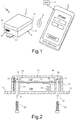
- Figure 1 shows a system for detecting and evaluating environmental quantities and events with modular approach and variable complexity, referred to hereinafter as system 1.
- the system 1 comprises a multisensor device 2 and a mobile device, in particular a mobile phone 3, connected together through a wireless connection 4 (represented schematically, for example a Bluetooth connection), intended to provide a desired connectivity, without having an excessive impact upon consumption of the multisensor device 2.
- a wireless connection 4 represented schematically, for example a Bluetooth connection
- the multisensor 2 comprises a casing 10 having a generally parallelepipedal shape with rounded edges.
- the casing 10 is formed by a first and a second half-shells 11, 12, fixed together, for example screwed, as illustrated more clearly in Figure 2 .
- One of the two half-shells here the first half-shell 11
- connection flanges 13 see also Figure 2 ) for enabling fixing on walls or apparata.
- each half-shell 11, 12 of the casing 10 defines a respective first and a second half-chambers 13A, 13B; first projections 15 extending inside the first half-chamber 13A towards the second half-shell 12, and second projections 16 extending inside the second half-chamber 13B towards the first half-shell 11; the first and the second projections 15, 16 facing each other.
- the first projections 15 are provided with respective through openings 17, and the second projections 16 are provided with blind holes 18, preferably threaded and aligned to the through openings 17.
- the casing 10 houses a support 20, for example, a printed circuit board, blocked between the first and the second half-shells 11, 12 of the casing 10 and precisely between the projections 15, 16 of the latter.
- the support 20 is provided with a pair of through holes 21, aligned to the through openings 17 and to the blind holes 18.
- screws 22 are inserted into the through openings 17 and are screwed into the blind holes 18, through the through holes 21, thus blocking the two half-shells 11, 12, as well as the support 20, together.
- other ways of fixing the two half-shells 11, 12 and the support 20 are possible, for example via snap-action retention elements, provided that these allow closing and re-opening of the casing 10.
- one of the two half-shells here the first half-shell 11, is provided with a connection opening 23, which connects the external environment with the half-chamber 13A of the casing 10.
- the half-chamber 13A is thus at the same pressure as the external environment, and a purposely provided pressure sensor (described below) may detect ambient pressure.
- One of the two half-shells here the second half-shell 12, has an opening 25 ( Figure 1 ) near a wireless connector 26 (described below), such as a USB connector.
- Figures 3A and 3B show the support 20, in view from above and from below respectively, which carries electronic components, connectors, and the electrical connection circuit.
- the support 20 has a first and a second faces 20A, 20B, each configured to carry a plurality of components, of a known and commercially available type.
- the first face 20A of the support 20 carries:
- the second face 20B of the support 20 carries:
- the support 20 preferably a printed circuit board, as already mentioned, further comprises the electrical-connection lines between the various components, for example conductive paths formed on the faces 20A, 20B or within the support 20, in a per se known manner and not illustrated.
- the support 20 is moreover provided with an acoustic opening 43, for fluidically connecting the two half-chambers 13A and 13B, keeping them at the same pressure and enabling passage of air and sound waves (for proper operation of the inertial sensors and environmental sensors 35, 36, in particular of the pressure sensor, the microphone, and the humidity sensor).
- the microcontroller 39 typically comprises, in a known way, a processing unit or module (not illustrated), and an integrated memory (also not illustrated), for storing data, information, and predefined libraries, aimed at implementation of the desired functions.
- the mobile phone 3 is a mobile phone of a smartphone type, enabling loading of applications or "apps" and has Bluetooth connectivity.
- the system 1 further comprises an application 5, which, once downloaded into the mobile phone 3, guides the user in use of the multisensor device 2.
- the system 1 enables use of the device 2 according to three modes, two of which are guided by the application 5. These modes of use refer to a basic or simple level of use of the device 2 (referred to hereinafter as “basic mode”), an expert level of use (“expert mode”), and an advanced level of use (“pro mode”), as described hereinafter with reference to Figures 4-8 .
- basic mode a basic or simple level of use of the device 2
- expert mode an expert level of use
- pro mode advanced level of use
- the application 5 is active in basic mode and initially presents a menu with some simple functions that have already been pre-loaded, such as baby-crying function, barometer, compass, data logger, event counter, level-meter, noise measurement, vibration monitoring, environmental monitoring, pedometer, and vibration monitoring.
- Other possible functions that may be envisaged by the application 5 comprise, for example, vehicle/object tracking.
- the pre-loaded functions do not require particular knowledge by the user and generally are started directly with selection of the specific function.
- the app 5 sends, via the Bluetooth connection 4, the request for the function selected by the user.
- This request is supplied to the microcontroller 39 and is a call to a specific predefined library from among the set of compiled libraries contained in the multisensor device 2. Therefore, the microcontroller 39, on the basis of the specific request, activates the sensors 35-36 requested by the function at issue, to collect and, if envisaged, process the corresponding data, in a per se known manner.
- the collected and possibly processed data may then be transmitted, via the Bluetooth connection 4, to the mobile phone 3 for display.
- the application 5 may provide, once the desired function has been selected, the possibility of displaying on the screen the sensors and units 35-36 involved in the requested function, as well as the type of performed action.
- Figure 5 shows the screenshots when selecting the compass function, which uses the data supplied by the gyroscope, the accelerometer, and the compensation magnetometer and performs combination and sending of the detected data via Bluetooth.
- the last item in the initial menu enables passage to the expert mode. Selection of this mode allows already stored functions to be called, existing functions to be modified, or create new functions to be created using a simple graphic tool.
- the application 5 asks the user to select the sensors to be used and presents a screenshot representing the various sensors that may be selected (see, for example, Figure 6 ). Once the sensors have been selected and the selection has been confirmed, the application asks the user to select a function to be executed and shows a screenshot representing a series of possible functions that may be performed with the selected sensors (see, for example, Figure 7 , in the case of choice of the temperature sensor, the humidity sensor, and the accelerometer).
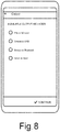
- the system After the function has been selected, the system enables addition of other functions and then asks the user to select the output, presenting the possibilities (saving to a memory card, sending to the USB port, sending via Bluetooth, and saving as input, i.e., as subprogram that may be subsequently used for creating more complex programs, Figure 8 ).
- the application allows saving of the new generated function with any desired name and sending it to the device 5.
- the request sent by the mobile phone 3 is received by the microcontroller 39, which activates the sensors selected by the user to collect and possibly process the corresponding data for carrying out the required function.
- the system 1 moreover enables a use level according to the advanced mode, which is activated by opening the casing 10 of the multisensor device 2 and connecting the latter (through the connectors 30) to an external programming apparatus (not illustrated).
- This mode assumes the user to be so expert and interested to be able to install the development tools on a personal computer and program the device in a standard programming language, for example C+++.
- the microcontroller 29 upon detecting the connection of the connectors 30, the microcontroller 29 goes into a reset condition and deactivates control through the mobile phone 3. Consequently, in this step, even if the application 5 attempts to supply commands to the device 2, these are ignored.
- the multisensor device 2 behaves like a normal evaluation board, which requires programming of the instructions of the desired advanced functions and communicates with the external programming apparatus through the connectors 30.
- the application 5 may maintain the communication between the multisensor device 2 and the mobile phone 3 and enable the mobile phone 3 to receive the new advanced functions for display and storage.
- the application 5 may enable display of the new advanced functions from the pre-loaded basic or expert functions.
- the application 5 may enable information and data display by the multisensor device 2.
- the system described herein has many advantages. In particular, in the basic mode, it does not require the user to invest time and attention in understanding operation of the system but also provides more advanced use modes, leading the user and enabling him to interact according to his own skills, time, and desires.
- the present system is extremely flexible and enables acquisition of a plurality of data and execution of a plurality of functions in an extremely simple way, for the less expert user, guiding him towards the discovery of new possibilities and creation of his own functions, without requiring writing of programming instructions.
- the system is not limited to a simple use mode, but enables the more enterprising and inquisitive user to generate, right from the start, particular functions which may be executed by the sensors, affording possibilities and stimulating the user's imagination to obtain more complex results, with acquisition of historic data and information, still without requiring the knowledge of programming techniques.
- the present system allows a professional use, enabling the advanced user both to exploit already present functions, saving time thereon, and to program more complex functions, according to his own needs, using the same system.
- the multisensor device 2 may be arranged in the open air, for enabling weather forecasting or monitoring of environmental parameters; may be applied to structures to be monitored, for example for enabling earthquakes detection, measurement of vibrations of objects such as motors or engines, and monitoring of time evolution of various physical quantities or events correlated thereto.
- the device in expert mode, may be programmed so as to create a mesh with other devices, using Bluetooth communication, and using the mobile phone 3 as interface.
- the shape of the casing may be any, and the support 20 may be fixed in position in a different way from what has been illustrated and described.
- the mobile device may be of a different type; for example, in addition to a mobile phone, it may be a tablet, a minitablet, a smartwatch, a smart multimedia reader, a smart e-reader, etc.
Landscapes
- Engineering & Computer Science (AREA)
- Physics & Mathematics (AREA)
- General Physics & Mathematics (AREA)
- Automation & Control Theory (AREA)
- Human Computer Interaction (AREA)
- Manufacturing & Machinery (AREA)
- Computer Hardware Design (AREA)
- Microelectronics & Electronic Packaging (AREA)
- Telephone Function (AREA)
- Arrangements For Transmission Of Measured Signals (AREA)
- Indicating And Signalling Devices For Elevators (AREA)
Abstract
Description
- The present invention relates to a device, a system, a method, and a computer product for detecting and evaluating environmental quantities and events with modular approach and variable complexity.
- As is known, various devices for consumer applications are present on the market, based upon environmental sensors, for example of a MEMS type, which enable detection of a plurality of quantities, such as temperature, speed, acceleration, pressure, etc. for performing one or a few simple preset functions, such as step counting, heart rate measurement, time-of-activity counting, atmospheric pressure measurement, etc. These apparata and devices are experiencing a major commercial success, since they allow information useful and/or attractive for users to be acquired, without requiring particular technical knowledge and/or long learning times. These apparata and devices are, however, dedicated and do not enable use of already available quantities and information to develop functions that are more complex or just different from the envisaged ones.
- Moreover, advanced development platforms are available on the market, comprising a plurality of sensors of different types and provided with external-connection structures. These platforms allow detection of a variety of environmental data and their transfer to a processing system, such as a personal computer or a complex processing apparatus, able to further process the received data in a programmable way to carry out complex functions, such as monitoring good movement paths to detect anomalies and faults and/or particular events. In this case, processing of the acquired data for performing complex functions and storing them require the development of suitable programs, using specific programming languages and operations. These systems are thus dedicated to a more restricted circle of users who are acquainted with the specific programming languages and are able to carry out the required operations, besides of availing the time necessary for development of the programs and being motivated thereto.
- Instead, no systems are commercially available that combine the simplicity of use of simpler devices, aimed at the consumer sector, with the more complex platforms, aimed at professional application.
- The availability of these systems is, on the other hand, desirable to simplify the development activities for more complex functions and increase the number of persons able to process the environmental data for performing relatively simple but programmable functions, for example exploiting the possibilities provided by IoT (Internet on Things) applications and/or simplifying the operations required of more advanced users.
- The aim of the present invention is to provide a system that fills the gap between devices dedicated to consumer use and complex systems requiring a high knowledge and programming commitment by providing the possibility of creating functions of a complexity correlated to the needs in a flexible way.
- According to the present invention, a device, a system, a method, and a computer product for detecting and evaluating environmental quantities and events are provided, as defined in the attached claims.
- For a better understanding of the present invention, an embodiment thereof is now described, purely by way of nonlimiting example, with reference to the attached drawings, wherein:
-
Figure 1 is a schematic and perspective illustration of components of the present detection system, comprising a device for detecting physical quantities, and a mobile phone; -
Figure 2 is a cross-section of the detection device ofFigure 1 ; -
Figures 3A and 3B are perspective views, from above and from below, respectively, of a part of the detection device of the system ofFigure 1 ; and -
Figures 4-8 show schematically some screenshots of an application that may be downloaded into the mobile phone of the system ofFigure 1 . -
Figure 1 shows a system for detecting and evaluating environmental quantities and events with modular approach and variable complexity, referred to hereinafter assystem 1. - The
system 1 comprises amultisensor device 2 and a mobile device, in particular a mobile phone 3, connected together through a wireless connection 4 (represented schematically, for example a Bluetooth connection), intended to provide a desired connectivity, without having an excessive impact upon consumption of themultisensor device 2. - The
multisensor 2 comprises acasing 10 having a generally parallelepipedal shape with rounded edges. Thecasing 10 is formed by a first and a second half-shells Figure 2 . One of the two half-shells (here the first half-shell 11) may be provided with connection flanges 13 (see alsoFigure 2 ) for enabling fixing on walls or apparata. - In detail,
Figure 2 , each half-shell casing 10 defines a respective first and a second half-chambers first projections 15 extending inside the first half-chamber 13A towards the second half-shell 12, andsecond projections 16 extending inside the second half-chamber 13B towards the first half-shell 11; the first and thesecond projections first projections 15 are provided with respective throughopenings 17, and thesecond projections 16 are provided withblind holes 18, preferably threaded and aligned to the throughopenings 17. - The
casing 10 houses asupport 20, for example, a printed circuit board, blocked between the first and the second half-shells casing 10 and precisely between theprojections support 20 is provided with a pair of throughholes 21, aligned to the throughopenings 17 and to theblind holes 18. During assembly,screws 22 are inserted into the throughopenings 17 and are screwed into theblind holes 18, through the throughholes 21, thus blocking the two half-shells support 20, together. However, other ways of fixing the two half-shells support 20 are possible, for example via snap-action retention elements, provided that these allow closing and re-opening of thecasing 10. - Moreover, one of the two half-shells, here the first half-
shell 11, is provided with a connection opening 23, which connects the external environment with the half-chamber 13A of thecasing 10. The half-chamber 13A is thus at the same pressure as the external environment, and a purposely provided pressure sensor (described below) may detect ambient pressure. - One of the two half-shells, here the second half-
shell 12, has an opening 25 (Figure 1 ) near a wireless connector 26 (described below), such as a USB connector. -
Figures 3A and 3B show thesupport 20, in view from above and from below respectively, which carries electronic components, connectors, and the electrical connection circuit. - In detail, the
support 20 has a first and asecond faces - For instance, the
first face 20A of thesupport 20 carries: -
connectors 30, designed to connect to an external apparatus (not illustrated) for programming amicrocontroller 39, carried by or on thesecond face 20B, for advanced use of thesystem 1, as discussed below; -
pushbuttons 31, comprising a reset pushbutton and two on/off pushbuttons, which may be used for advanced use of thesystem 1 for deactivation/activation of parts of themultisensor device 2, in particular connected to themicrocontroller 39, for example, for debugging purposes; and - a
support 32 for amemory 33, for example an SD memory card, for storing data, measurements, and results acquired by themultisensor device 2. - Moreover, the
second face 20B of thesupport 20 carries: - the
USB connector 26, for example of the micro-USB type; - a plurality of
inertial sensors 35, typically MEMS components and including, for example, a gyroscope, an accelerometer, a pressure sensor, and a microphone; - a plurality of
environmental sensors 36, for example including a temperature sensor, a humidity sensor, and a magnetometer; - a
support 37 and a wireless communication circuit or module 38 (for example Bluetooth); - the
microcontroller 39; and -
connectors 40 for one ormore supply batteries 41, for example lithium-polymer batteries; theconnectors 40 are connected, through conductive paths and lines (not illustrated) to all the electronic components carried by or on thesupport 20, as well as to theUSB connector 26 for enabling charging of thesupply batteries 41; and -
electronic components 42. - The
support 20, preferably a printed circuit board, as already mentioned, further comprises the electrical-connection lines between the various components, for example conductive paths formed on thefaces support 20, in a per se known manner and not illustrated. Thesupport 20 is moreover provided with anacoustic opening 43, for fluidically connecting the two half-chambers environmental sensors - The
microcontroller 39 typically comprises, in a known way, a processing unit or module (not illustrated), and an integrated memory (also not illustrated), for storing data, information, and predefined libraries, aimed at implementation of the desired functions. - With reference again to
Figure 1 , the mobile phone 3 is a mobile phone of a smartphone type, enabling loading of applications or "apps" and has Bluetooth connectivity. - The
system 1 further comprises anapplication 5, which, once downloaded into the mobile phone 3, guides the user in use of themultisensor device 2. - In detail, the
system 1 enables use of thedevice 2 according to three modes, two of which are guided by theapplication 5. These modes of use refer to a basic or simple level of use of the device 2 (referred to hereinafter as "basic mode"), an expert level of use ("expert mode"), and an advanced level of use ("pro mode"), as described hereinafter with reference toFigures 4-8 . - In detail (
Figure 4 ), theapplication 5 is active in basic mode and initially presents a menu with some simple functions that have already been pre-loaded, such as baby-crying function, barometer, compass, data logger, event counter, level-meter, noise measurement, vibration monitoring, environmental monitoring, pedometer, and vibration monitoring. Other possible functions that may be envisaged by theapplication 5 comprise, for example, vehicle/object tracking. - The pre-loaded functions do not require particular knowledge by the user and generally are started directly with selection of the specific function. To this end, the
app 5 sends, via the Bluetoothconnection 4, the request for the function selected by the user. This request is supplied to themicrocontroller 39 and is a call to a specific predefined library from among the set of compiled libraries contained in themultisensor device 2. Therefore, themicrocontroller 39, on the basis of the specific request, activates the sensors 35-36 requested by the function at issue, to collect and, if envisaged, process the corresponding data, in a per se known manner. The collected and possibly processed data may then be transmitted, via the Bluetoothconnection 4, to the mobile phone 3 for display. - To increase the user awareness and stimulate his curiosity towards a more personal use, the
application 5 may provide, once the desired function has been selected, the possibility of displaying on the screen the sensors and units 35-36 involved in the requested function, as well as the type of performed action. For instance,Figure 5 shows the screenshots when selecting the compass function, which uses the data supplied by the gyroscope, the accelerometer, and the compensation magnetometer and performs combination and sending of the detected data via Bluetooth. - The last item in the initial menu enables passage to the expert mode. Selection of this mode allows already stored functions to be called, existing functions to be modified, or create new functions to be created using a simple graphic tool. To this end, when creation of a new function is selected, the
application 5 asks the user to select the sensors to be used and presents a screenshot representing the various sensors that may be selected (see, for example,Figure 6 ). Once the sensors have been selected and the selection has been confirmed, the application asks the user to select a function to be executed and shows a screenshot representing a series of possible functions that may be performed with the selected sensors (see, for example,Figure 7 , in the case of choice of the temperature sensor, the humidity sensor, and the accelerometer). After the function has been selected, the system enables addition of other functions and then asks the user to select the output, presenting the possibilities (saving to a memory card, sending to the USB port, sending via Bluetooth, and saving as input, i.e., as subprogram that may be subsequently used for creating more complex programs,Figure 8 ). The application allows saving of the new generated function with any desired name and sending it to thedevice 5. In this case, the request sent by the mobile phone 3 is received by themicrocontroller 39, which activates the sensors selected by the user to collect and possibly process the corresponding data for carrying out the required function. - As indicated, the
system 1 moreover enables a use level according to the advanced mode, which is activated by opening thecasing 10 of themultisensor device 2 and connecting the latter (through the connectors 30) to an external programming apparatus (not illustrated). This mode assumes the user to be so expert and interested to be able to install the development tools on a personal computer and program the device in a standard programming language, for example C+++. In particular, upon detecting the connection of theconnectors 30, the microcontroller 29 goes into a reset condition and deactivates control through the mobile phone 3. Consequently, in this step, even if theapplication 5 attempts to supply commands to thedevice 2, these are ignored. In particular, in this step, themultisensor device 2 behaves like a normal evaluation board, which requires programming of the instructions of the desired advanced functions and communicates with the external programming apparatus through theconnectors 30. Thereby, at the end of programming, theapplication 5 may maintain the communication between themultisensor device 2 and the mobile phone 3 and enable the mobile phone 3 to receive the new advanced functions for display and storage. In this case, at subsequent start-up of the system, theapplication 5 may enable display of the new advanced functions from the pre-loaded basic or expert functions. Moreover, during the advanced-programming process, theapplication 5 may enable information and data display by themultisensor device 2. - The system described herein has many advantages. In particular, in the basic mode, it does not require the user to invest time and attention in understanding operation of the system but also provides more advanced use modes, leading the user and enabling him to interact according to his own skills, time, and desires. The present system is extremely flexible and enables acquisition of a plurality of data and execution of a plurality of functions in an extremely simple way, for the less expert user, guiding him towards the discovery of new possibilities and creation of his own functions, without requiring writing of programming instructions. However, the system is not limited to a simple use mode, but enables the more enterprising and inquisitive user to generate, right from the start, particular functions which may be executed by the sensors, affording possibilities and stimulating the user's imagination to obtain more complex results, with acquisition of historic data and information, still without requiring the knowledge of programming techniques. Finally, the present system allows a professional use, enabling the advanced user both to exploit already present functions, saving time thereon, and to program more complex functions, according to his own needs, using the same system.
- The system finds application in a wide range of situations and may be used in different environments. For instance, the
multisensor device 2 may be arranged in the open air, for enabling weather forecasting or monitoring of environmental parameters; may be applied to structures to be monitored, for example for enabling earthquakes detection, measurement of vibrations of objects such as motors or engines, and monitoring of time evolution of various physical quantities or events correlated thereto. Moreover, the device, in expert mode, may be programmed so as to create a mesh with other devices, using Bluetooth communication, and using the mobile phone 3 as interface. - Finally, it is clear that modifications and variations may be made to the device, the system, the method, and the computer product for detection and evaluation, described and illustrated herein, without thereby departing from the scope of the present invention, as defined in the attached claims.
- For instance, the shape of the casing may be any, and the
support 20 may be fixed in position in a different way from what has been illustrated and described. - Furthermore, the mobile device may be of a different type; for example, in addition to a mobile phone, it may be a tablet, a minitablet, a smartwatch, a smart multimedia reader, a smart e-reader, etc.
Claims (14)
- A detection and evaluation device (2) for environmental quantities and events, comprising:a containment casing (10);a support (20) in the containment casing;a plurality of inertial sensors (35), carried by the support;a plurality of environmental sensors (36), carried by the support;a processing unit (39), carried by the support and coupled to the inertial sensors and to the environmental sensors;a wireless connection unit (38), coupled to the processing unit;programming connectors (30), coupled to the processing unit (39) and configured to couple to an external programming unit to receive programming instructions of the processing unit; anda storage structure (33), coupled to the processing unit,the storage structure (33) configured to store detection data supplied by the inertial sensors and environmental sensors, as well as pre-loaded detection and evaluation functions and detection and evaluation functions supplied through the programming connectors (30),wherein the device is configured to receive, throught the wireless connection unit (38), a request to execute a function corresponding to an operation mode selected among basic-use mode, expert-use mode and advanced-use mode, to activate at least one sensor selected among the inertial sensors and the environmental sensors and to send corresponding data through the wireless connection unit.
- The detection and evaluation device according to claim 1, further comprising a wired connection port (26) coupled to the processing unit, such as a USB port.
- The detection and evaluation device according to claim 1 or 2, wherein the wireless connection unit (38) is a Bluetooth unit.
- The detection and evaluation device according to any of the preceding claims, wherein the containment casing (10) has a generally parallelepipedal shape, is formed by a pair of half-shells (11, 12), fixed together, and has openings (23) for the passage of air, one (11) of the half-shells having fixing flanges (13).
- The detection and evaluation device according to any of the preceding claims, wherein the processing unit (39) is configured to execute the following steps:
upon receiving from the wireless connection unit (38) a request to execute a specific function:select the corresponding sensor among the inertial sensors (35) and the environmental sensors (36);receive measurement data from the at least one selected sensor;perform the specific function based on measurement data received by the at least one selected sensor, thereby obtaining specific-function related data; andsend the specific-function related data to the wireless connection unit. - The detection and evaluation device according to any of the preceding claims, wherein the processing unit (39) is configured to execute the following steps:detect connection of the programming connectors (30);receive from the programming connectors (30) instructions regarding the advanced function;store the instructions regarding the advanced function; andsend advanced function information to the wireless connection unit (38).
- A system for detecting and evaluating environmental quantities and events, comprising the detection and evaluation device (2) according to any of the preceding claims, and a mobile device (3), connected together through a wireless connection (4), wherein the mobile device (3) is configured to store an application for detecting and evaluating environmental quantities and events, including a basic-use mode, an expert-use mode, and an advanced-use mode.
- The system according to the preceding claim, wherein the application is configured to execute the following steps:display a plurality of executable functions and an expert-use function;detect selection of a specific function among the plurality of executable functions or selection of the expert-use function;if selection of a specific function is detected, send to the detection and evaluation device a request for activating the specific function using the wireless connection (4);receive, from the detection and evaluation device, detection and evaluation data regarding the specific function; anddisplay the detection and evaluation data regarding the specific function; andif selection of the expert-use function is detected, activating the expert-use mode.
- The system according to the preceding claim, wherein activating the expert-use mode comprises the steps of:displaying a list of sensors and detectors available in the detection and evaluation device;detecting selection of at least one of the sensors and detectors in the list;showing a list of expert functions, comprising at least one expert function that may be executed by the sensor or detector selected;detecting selection of a specific expert function in the list of expert functions;sending to the detection and evaluation device a request for expert use;receiving, from the detection and evaluation device, detection and evaluation data regarding the expert-use function; anddisplaying the detection and evaluation data regarding the expert-use function.
- The system according to any of claims 7-9, wherein the detection and evaluation device (2) comprises a containment casing (10) and programming connectors (30) configured to couple to an external programming unit,
the detection and evaluation device (2) being configured to execute the following steps:detect the connection of the programming connectors (30) ;receive instructions regarding an advanced function through the programming connectors (30);store the advanced function; andsend advanced function information to the mobile device (3),and wherein the application (5) is configured to execute the following steps:receive, from the detection and evaluation device (2), the advanced-function information; andincluding the advanced function in the list of the executable functions. - A method for detecting and evaluating environmental quantities and events, using the detection and evaluation device (2) according to any of claims 1-6 and the system according to any of claims 7-10, comprising the steps of:displaying, via the mobile device, a plurality of executable functions and an expert-use function;detecting, via the mobile device, selection of a specific function among the plurality of executable functions or selection of the expert-use function;if selection of a specific function is detected, sending, via the mobile device, a request for activation of the specific function using the wireless connection (4);receiving, by the detection and evaluation device, a request for executing the specific function;activating, by the processing unit, at least one selected sensor among the inertial sensors and the environmental sensors;receiving, by the processing unit, measurement data from the at least one selected sensor;performing, by the processing unit, the specific function on the basis of measurement data received from the at least one selected sensor;sending to the mobile device, by the detection and evaluation device, detection and evaluation data regarding the specific function, using the wireless connection;receiving, by the mobile device, the detection and evaluation data regarding the specific function;displaying, by the mobile device, the detection and evaluation data regarding the specific function; andif selection of the expert-use function is detected, activating the expert-use mode.
- The method according to preceding claim, wherein activating the expert-use mode comprises:displaying, by the mobile device, a list of sensors and detectors available in the detection and evaluation device;detecting, by the mobile device, selection of at least one of the sensors and detectors in the list;showing, by the mobile device, a list of expert functions comprising at least one expert function executable by the selected sensor or detector;detecting, by the mobile device, selection of an expert function from the list of expert functions;sending, by the mobile device, a request for expert function to the detection and evaluation device;receiving, by the detection and evaluation device, the request for expert function;executing, by the detection and evaluation device, the expert function and acquiring detection and evaluation data;sending to the mobile device, by the detection and evaluation device, the detection and evaluation data acquired;receiving, by the mobile device, the acquired detection and evaluation data from the detection and evaluation device; anddisplaying, by the mobile device, the detection and evaluation data acquired regarding the expert-use function.
- The method according to claim 11 or 12, comprising the steps of:detecting, by the detection and evaluation device, the connection of programming connectors (30) in the detection and evaluation device;receiving, by the detection and evaluation device through programming connectors, instructions regarding an advanced function;storing, by the detection and evaluation device, the advanced function;sending, by the detection and evaluation device, advanced function information to the mobile device; andincluding, by the mobile device, the advanced function within the list of executable functions.
- A processing device readable storage medium comprising program code which encodes the method according to any of claims 11-13 to be executed in the mobile device according to any of the claims 7-10.
Applications Claiming Priority (1)
| Application Number | Priority Date | Filing Date | Title |
|---|---|---|---|
| IT102019000000082A IT201900000082A1 (en) | 2019-01-04 | 2019-01-04 | DEVICE, SYSTEM, METHOD AND IT PRODUCT FOR DETECTION AND EVALUATION OF ENVIRONMENTAL VALUES AND EVENTS WITH A MODULAR APPROACH AND VARIABLE COMPLEXITY |
Publications (2)
| Publication Number | Publication Date |
|---|---|
| EP3677876A1 true EP3677876A1 (en) | 2020-07-08 |
| EP3677876B1 EP3677876B1 (en) | 2023-08-02 |
Family
ID=65952008
Family Applications (1)
| Application Number | Title | Priority Date | Filing Date |
|---|---|---|---|
| EP19220225.7A Active EP3677876B1 (en) | 2019-01-04 | 2019-12-31 | Device, system, method, and computer product for detecting and evaluating environmental quantities and events with modular approach and variable complexity |
Country Status (4)
| Country | Link |
|---|---|
| US (2) | US11650566B2 (en) |
| EP (1) | EP3677876B1 (en) |
| CN (1) | CN111412943B (en) |
| IT (1) | IT201900000082A1 (en) |
Citations (4)
| Publication number | Priority date | Publication date | Assignee | Title |
|---|---|---|---|---|
| US8162846B2 (en) * | 2002-11-18 | 2012-04-24 | Epley Research Llc | Head-stabilized, nystagmus-based repositioning apparatus, system and methodology |
| EP2863328A1 (en) * | 2010-11-24 | 2015-04-22 | NIKE Innovate C.V. | Method and system for automated personal training that includes training programs |
| WO2015087164A1 (en) * | 2013-12-10 | 2015-06-18 | 4Iiii Innovations Inc. | Signature based monitoring systems and methods |
| US20160303455A1 (en) * | 2015-04-15 | 2016-10-20 | Kenith CARSWELL | System, method and apparatus for improving human response, sensitivity and performance |
Family Cites Families (11)
| Publication number | Priority date | Publication date | Assignee | Title |
|---|---|---|---|---|
| WO2007118247A2 (en) * | 2006-04-07 | 2007-10-18 | Qualcomm Incorporated | Sensor interface, and methods and apparatus pertaining to same |
| US9457256B2 (en) * | 2010-11-05 | 2016-10-04 | Nike, Inc. | Method and system for automated personal training that includes training programs |
| EP2525581A3 (en) * | 2011-05-17 | 2013-10-23 | Samsung Electronics Co., Ltd. | Apparatus and Method for Converting 2D Content into 3D Content, and Computer-Readable Storage Medium Thereof |
| US9483558B2 (en) * | 2013-05-29 | 2016-11-01 | Commvault Systems, Inc. | Assessing user performance in a community of users of data storage resources |
| EP3003148A1 (en) * | 2013-05-31 | 2016-04-13 | NIKE Innovate C.V. | Dynamic sampling |
| US9648446B2 (en) * | 2015-09-22 | 2017-05-09 | Veniam, Inc. | Systems and methods for shipping management in a network of moving things |
| CN107764280B (en) * | 2017-10-20 | 2021-11-26 | 郭寒松 | Multi-mode accurate step counting method and device |
| CN107854122A (en) * | 2017-11-27 | 2018-03-30 | 宋鹏飞 | Flexibility wearing physical signs detection device |
| CN107861743A (en) * | 2017-12-12 | 2018-03-30 | 深圳市同创机电体化技术有限公司 | It is a kind of with optic communication can with field upgrade and set light curtain system and control method |
| CN108197068A (en) * | 2017-12-27 | 2018-06-22 | 中国科学院微电子研究所 | Embedded real-time data acquisition and storage system and method thereof |
| US10705194B2 (en) * | 2018-03-21 | 2020-07-07 | Zoox, Inc. | Automated detection of sensor miscalibration |
-
2019
- 2019-01-04 IT IT102019000000082A patent/IT201900000082A1/en unknown
- 2019-12-31 EP EP19220225.7A patent/EP3677876B1/en active Active
-
2020
- 2020-01-02 CN CN202010002980.4A patent/CN111412943B/en active Active
- 2020-01-03 US US16/734,233 patent/US11650566B2/en active Active
-
2023
- 2023-04-14 US US18/301,002 patent/US20230251621A1/en active Pending
Patent Citations (4)
| Publication number | Priority date | Publication date | Assignee | Title |
|---|---|---|---|---|
| US8162846B2 (en) * | 2002-11-18 | 2012-04-24 | Epley Research Llc | Head-stabilized, nystagmus-based repositioning apparatus, system and methodology |
| EP2863328A1 (en) * | 2010-11-24 | 2015-04-22 | NIKE Innovate C.V. | Method and system for automated personal training that includes training programs |
| WO2015087164A1 (en) * | 2013-12-10 | 2015-06-18 | 4Iiii Innovations Inc. | Signature based monitoring systems and methods |
| US20160303455A1 (en) * | 2015-04-15 | 2016-10-20 | Kenith CARSWELL | System, method and apparatus for improving human response, sensitivity and performance |
Also Published As
| Publication number | Publication date |
|---|---|
| IT201900000082A1 (en) | 2020-07-04 |
| CN111412943B (en) | 2023-08-15 |
| EP3677876B1 (en) | 2023-08-02 |
| US20200218228A1 (en) | 2020-07-09 |
| US11650566B2 (en) | 2023-05-16 |
| US20230251621A1 (en) | 2023-08-10 |
| CN111412943A (en) | 2020-07-14 |
Similar Documents
| Publication | Publication Date | Title |
|---|---|---|
| US8441371B2 (en) | Method and mechanism for assisted diagnosis and maintenance of health monitoring system | |
| CN108463832B (en) | Electronic device and process execution method based on hardware diagnosis result | |
| CN110209639B (en) | Information processing method, device and system | |
| US10748391B2 (en) | Haptic signal conversion system | |
| EP2846135A2 (en) | Portable Electronic Device with Environmental Sensor | |
| US12138530B2 (en) | Controlling data processing | |
| US9329661B2 (en) | Information processing method and electronic device | |
| WO2012044262A1 (en) | Embedded system design, programming, and simulation architecture | |
| CN102236030A (en) | Inertial measurement simulation analyzing method, terminal and system | |
| CN114090432B (en) | Method, system, device, electronic equipment and storage medium for simulation test | |
| EP3677876B1 (en) | Device, system, method, and computer product for detecting and evaluating environmental quantities and events with modular approach and variable complexity | |
| US20160171909A1 (en) | Wireless multi-sensor device and software system for measuring physical parameters | |
| Zhi-An et al. | The development and application of sensor based on android | |
| US20160056902A1 (en) | Systems for module and modular mobile electronic device testing | |
| CN115328770A (en) | Application program testing method and device, electronic equipment and storage medium | |
| KR20190001926A (en) | Systems and methods for determining a device's acceleration using its internal microphone | |
| KR102128004B1 (en) | Apparatus and method for software validation | |
| KR102567368B1 (en) | An electronic device and a method for displaying history of use | |
| CN112306847B (en) | Coverage rate data generation method, device and system | |
| CN107632266B (en) | Mobile terminal, test system and test method of mobile terminal | |
| CN114489154A (en) | Control method, control device, handle and medium | |
| Brandherm et al. | Presentation of a Modular Framework for Interpretation of Sensor Data With Dynamic Bayesian Networks on Mobile Devices. | |
| Babiuch | . Net Micro Framework gadgeteer measurement applications development | |
| CN207270687U (en) | A kind of binocular handle system, device and AR devices | |
| Olaniyan et al. | Implementation of a Microcontroller Based GSM Alert Distress System |
Legal Events
| Date | Code | Title | Description |
|---|---|---|---|
| PUAI | Public reference made under article 153(3) epc to a published international application that has entered the european phase |
Free format text: ORIGINAL CODE: 0009012 |
|
| STAA | Information on the status of an ep patent application or granted ep patent |
Free format text: STATUS: THE APPLICATION HAS BEEN PUBLISHED |
|
| AK | Designated contracting states |
Kind code of ref document: A1 Designated state(s): AL AT BE BG CH CY CZ DE DK EE ES FI FR GB GR HR HU IE IS IT LI LT LU LV MC MK MT NL NO PL PT RO RS SE SI SK SM TR |
|
| AX | Request for extension of the european patent |
Extension state: BA ME |
|
| STAA | Information on the status of an ep patent application or granted ep patent |
Free format text: STATUS: REQUEST FOR EXAMINATION WAS MADE |
|
| 17P | Request for examination filed |
Effective date: 20201228 |
|
| RBV | Designated contracting states (corrected) |
Designated state(s): AL AT BE BG CH CY CZ DE DK EE ES FI FR GB GR HR HU IE IS IT LI LT LU LV MC MK MT NL NO PL PT RO RS SE SI SK SM TR |
|
| STAA | Information on the status of an ep patent application or granted ep patent |
Free format text: STATUS: EXAMINATION IS IN PROGRESS |
|
| 17Q | First examination report despatched |
Effective date: 20210811 |
|
| GRAP | Despatch of communication of intention to grant a patent |
Free format text: ORIGINAL CODE: EPIDOSNIGR1 |
|
| STAA | Information on the status of an ep patent application or granted ep patent |
Free format text: STATUS: GRANT OF PATENT IS INTENDED |
|
| INTG | Intention to grant announced |
Effective date: 20230220 |
|
| GRAS | Grant fee paid |
Free format text: ORIGINAL CODE: EPIDOSNIGR3 |
|
| GRAA | (expected) grant |
Free format text: ORIGINAL CODE: 0009210 |
|
| STAA | Information on the status of an ep patent application or granted ep patent |
Free format text: STATUS: THE PATENT HAS BEEN GRANTED |
|
| AK | Designated contracting states |
Kind code of ref document: B1 Designated state(s): AL AT BE BG CH CY CZ DE DK EE ES FI FR GB GR HR HU IE IS IT LI LT LU LV MC MK MT NL NO PL PT RO RS SE SI SK SM TR |
|
| REG | Reference to a national code |
Ref country code: GB Ref legal event code: FG4D |
|
| REG | Reference to a national code |
Ref country code: CH Ref legal event code: EP |
|
| REG | Reference to a national code |
Ref country code: DE Ref legal event code: R096 Ref document number: 602019033967 Country of ref document: DE |
|
| REG | Reference to a national code |
Ref country code: IE Ref legal event code: FG4D |
|
| REG | Reference to a national code |
Ref country code: LT Ref legal event code: MG9D |
|
| REG | Reference to a national code |
Ref country code: NL Ref legal event code: MP Effective date: 20230802 |
|
| REG | Reference to a national code |
Ref country code: AT Ref legal event code: MK05 Ref document number: 1595271 Country of ref document: AT Kind code of ref document: T Effective date: 20230802 |
|
| PG25 | Lapsed in a contracting state [announced via postgrant information from national office to epo] |
Ref country code: GR Free format text: LAPSE BECAUSE OF FAILURE TO SUBMIT A TRANSLATION OF THE DESCRIPTION OR TO PAY THE FEE WITHIN THE PRESCRIBED TIME-LIMIT Effective date: 20231103 |
|
| PG25 | Lapsed in a contracting state [announced via postgrant information from national office to epo] |
Ref country code: IS Free format text: LAPSE BECAUSE OF FAILURE TO SUBMIT A TRANSLATION OF THE DESCRIPTION OR TO PAY THE FEE WITHIN THE PRESCRIBED TIME-LIMIT Effective date: 20231202 |
|
| PG25 | Lapsed in a contracting state [announced via postgrant information from national office to epo] |
Ref country code: SE Free format text: LAPSE BECAUSE OF FAILURE TO SUBMIT A TRANSLATION OF THE DESCRIPTION OR TO PAY THE FEE WITHIN THE PRESCRIBED TIME-LIMIT Effective date: 20230802 Ref country code: RS Free format text: LAPSE BECAUSE OF FAILURE TO SUBMIT A TRANSLATION OF THE DESCRIPTION OR TO PAY THE FEE WITHIN THE PRESCRIBED TIME-LIMIT Effective date: 20230802 Ref country code: PT Free format text: LAPSE BECAUSE OF FAILURE TO SUBMIT A TRANSLATION OF THE DESCRIPTION OR TO PAY THE FEE WITHIN THE PRESCRIBED TIME-LIMIT Effective date: 20231204 Ref country code: NO Free format text: LAPSE BECAUSE OF FAILURE TO SUBMIT A TRANSLATION OF THE DESCRIPTION OR TO PAY THE FEE WITHIN THE PRESCRIBED TIME-LIMIT Effective date: 20231102 Ref country code: NL Free format text: LAPSE BECAUSE OF FAILURE TO SUBMIT A TRANSLATION OF THE DESCRIPTION OR TO PAY THE FEE WITHIN THE PRESCRIBED TIME-LIMIT Effective date: 20230802 Ref country code: LV Free format text: LAPSE BECAUSE OF FAILURE TO SUBMIT A TRANSLATION OF THE DESCRIPTION OR TO PAY THE FEE WITHIN THE PRESCRIBED TIME-LIMIT Effective date: 20230802 Ref country code: LT Free format text: LAPSE BECAUSE OF FAILURE TO SUBMIT A TRANSLATION OF THE DESCRIPTION OR TO PAY THE FEE WITHIN THE PRESCRIBED TIME-LIMIT Effective date: 20230802 Ref country code: IS Free format text: LAPSE BECAUSE OF FAILURE TO SUBMIT A TRANSLATION OF THE DESCRIPTION OR TO PAY THE FEE WITHIN THE PRESCRIBED TIME-LIMIT Effective date: 20231202 Ref country code: HR Free format text: LAPSE BECAUSE OF FAILURE TO SUBMIT A TRANSLATION OF THE DESCRIPTION OR TO PAY THE FEE WITHIN THE PRESCRIBED TIME-LIMIT Effective date: 20230802 Ref country code: GR Free format text: LAPSE BECAUSE OF FAILURE TO SUBMIT A TRANSLATION OF THE DESCRIPTION OR TO PAY THE FEE WITHIN THE PRESCRIBED TIME-LIMIT Effective date: 20231103 Ref country code: FI Free format text: LAPSE BECAUSE OF FAILURE TO SUBMIT A TRANSLATION OF THE DESCRIPTION OR TO PAY THE FEE WITHIN THE PRESCRIBED TIME-LIMIT Effective date: 20230802 Ref country code: AT Free format text: LAPSE BECAUSE OF FAILURE TO SUBMIT A TRANSLATION OF THE DESCRIPTION OR TO PAY THE FEE WITHIN THE PRESCRIBED TIME-LIMIT Effective date: 20230802 |
|
| PG25 | Lapsed in a contracting state [announced via postgrant information from national office to epo] |
Ref country code: PL Free format text: LAPSE BECAUSE OF FAILURE TO SUBMIT A TRANSLATION OF THE DESCRIPTION OR TO PAY THE FEE WITHIN THE PRESCRIBED TIME-LIMIT Effective date: 20230802 |
|
| PG25 | Lapsed in a contracting state [announced via postgrant information from national office to epo] |
Ref country code: ES Free format text: LAPSE BECAUSE OF FAILURE TO SUBMIT A TRANSLATION OF THE DESCRIPTION OR TO PAY THE FEE WITHIN THE PRESCRIBED TIME-LIMIT Effective date: 20230802 |
|
| PG25 | Lapsed in a contracting state [announced via postgrant information from national office to epo] |
Ref country code: SM Free format text: LAPSE BECAUSE OF FAILURE TO SUBMIT A TRANSLATION OF THE DESCRIPTION OR TO PAY THE FEE WITHIN THE PRESCRIBED TIME-LIMIT Effective date: 20230802 Ref country code: RO Free format text: LAPSE BECAUSE OF FAILURE TO SUBMIT A TRANSLATION OF THE DESCRIPTION OR TO PAY THE FEE WITHIN THE PRESCRIBED TIME-LIMIT Effective date: 20230802 Ref country code: ES Free format text: LAPSE BECAUSE OF FAILURE TO SUBMIT A TRANSLATION OF THE DESCRIPTION OR TO PAY THE FEE WITHIN THE PRESCRIBED TIME-LIMIT Effective date: 20230802 Ref country code: EE Free format text: LAPSE BECAUSE OF FAILURE TO SUBMIT A TRANSLATION OF THE DESCRIPTION OR TO PAY THE FEE WITHIN THE PRESCRIBED TIME-LIMIT Effective date: 20230802 Ref country code: DK Free format text: LAPSE BECAUSE OF FAILURE TO SUBMIT A TRANSLATION OF THE DESCRIPTION OR TO PAY THE FEE WITHIN THE PRESCRIBED TIME-LIMIT Effective date: 20230802 Ref country code: CZ Free format text: LAPSE BECAUSE OF FAILURE TO SUBMIT A TRANSLATION OF THE DESCRIPTION OR TO PAY THE FEE WITHIN THE PRESCRIBED TIME-LIMIT Effective date: 20230802 Ref country code: SK Free format text: LAPSE BECAUSE OF FAILURE TO SUBMIT A TRANSLATION OF THE DESCRIPTION OR TO PAY THE FEE WITHIN THE PRESCRIBED TIME-LIMIT Effective date: 20230802 |
|
| REG | Reference to a national code |
Ref country code: DE Ref legal event code: R097 Ref document number: 602019033967 Country of ref document: DE |
|
| PG25 | Lapsed in a contracting state [announced via postgrant information from national office to epo] |
Ref country code: IT Free format text: LAPSE BECAUSE OF FAILURE TO SUBMIT A TRANSLATION OF THE DESCRIPTION OR TO PAY THE FEE WITHIN THE PRESCRIBED TIME-LIMIT Effective date: 20230802 |
|
| PLBE | No opposition filed within time limit |
Free format text: ORIGINAL CODE: 0009261 |
|
| STAA | Information on the status of an ep patent application or granted ep patent |
Free format text: STATUS: NO OPPOSITION FILED WITHIN TIME LIMIT |
|
| 26N | No opposition filed |
Effective date: 20240503 |
|
| PG25 | Lapsed in a contracting state [announced via postgrant information from national office to epo] |
Ref country code: SI Free format text: LAPSE BECAUSE OF FAILURE TO SUBMIT A TRANSLATION OF THE DESCRIPTION OR TO PAY THE FEE WITHIN THE PRESCRIBED TIME-LIMIT Effective date: 20230802 |
|
| REG | Reference to a national code |
Ref country code: CH Ref legal event code: PL |
|
| PG25 | Lapsed in a contracting state [announced via postgrant information from national office to epo] |
Ref country code: LU Free format text: LAPSE BECAUSE OF NON-PAYMENT OF DUE FEES Effective date: 20231231 |
|
| PG25 | Lapsed in a contracting state [announced via postgrant information from national office to epo] |
Ref country code: MC Free format text: LAPSE BECAUSE OF FAILURE TO SUBMIT A TRANSLATION OF THE DESCRIPTION OR TO PAY THE FEE WITHIN THE PRESCRIBED TIME-LIMIT Effective date: 20230802 |
|
| GBPC | Gb: european patent ceased through non-payment of renewal fee |
Effective date: 20231231 |
|
| REG | Reference to a national code |
Ref country code: BE Ref legal event code: MM Effective date: 20231231 |
|
| PG25 | Lapsed in a contracting state [announced via postgrant information from national office to epo] |
Ref country code: MC Free format text: LAPSE BECAUSE OF FAILURE TO SUBMIT A TRANSLATION OF THE DESCRIPTION OR TO PAY THE FEE WITHIN THE PRESCRIBED TIME-LIMIT Effective date: 20230802 Ref country code: LU Free format text: LAPSE BECAUSE OF NON-PAYMENT OF DUE FEES Effective date: 20231231 |
|
| REG | Reference to a national code |
Ref country code: IE Ref legal event code: MM4A |
|
| PG25 | Lapsed in a contracting state [announced via postgrant information from national office to epo] |
Ref country code: IE Free format text: LAPSE BECAUSE OF NON-PAYMENT OF DUE FEES Effective date: 20231231 |
|
| PG25 | Lapsed in a contracting state [announced via postgrant information from national office to epo] |
Ref country code: GB Free format text: LAPSE BECAUSE OF NON-PAYMENT OF DUE FEES Effective date: 20231231 |
|
| PG25 | Lapsed in a contracting state [announced via postgrant information from national office to epo] |
Ref country code: BE Free format text: LAPSE BECAUSE OF NON-PAYMENT OF DUE FEES Effective date: 20231231 |
|
| PG25 | Lapsed in a contracting state [announced via postgrant information from national office to epo] |
Ref country code: FR Free format text: LAPSE BECAUSE OF NON-PAYMENT OF DUE FEES Effective date: 20231231 |
|
| PG25 | Lapsed in a contracting state [announced via postgrant information from national office to epo] |
Ref country code: CH Free format text: LAPSE BECAUSE OF NON-PAYMENT OF DUE FEES Effective date: 20231231 |
|
| PG25 | Lapsed in a contracting state [announced via postgrant information from national office to epo] |
Ref country code: IE Free format text: LAPSE BECAUSE OF NON-PAYMENT OF DUE FEES Effective date: 20231231 Ref country code: GB Free format text: LAPSE BECAUSE OF NON-PAYMENT OF DUE FEES Effective date: 20231231 Ref country code: FR Free format text: LAPSE BECAUSE OF NON-PAYMENT OF DUE FEES Effective date: 20231231 Ref country code: CH Free format text: LAPSE BECAUSE OF NON-PAYMENT OF DUE FEES Effective date: 20231231 Ref country code: BE Free format text: LAPSE BECAUSE OF NON-PAYMENT OF DUE FEES Effective date: 20231231 |
|
| PG25 | Lapsed in a contracting state [announced via postgrant information from national office to epo] |
Ref country code: BG Free format text: LAPSE BECAUSE OF FAILURE TO SUBMIT A TRANSLATION OF THE DESCRIPTION OR TO PAY THE FEE WITHIN THE PRESCRIBED TIME-LIMIT Effective date: 20230802 |
|
| PG25 | Lapsed in a contracting state [announced via postgrant information from national office to epo] |
Ref country code: BG Free format text: LAPSE BECAUSE OF FAILURE TO SUBMIT A TRANSLATION OF THE DESCRIPTION OR TO PAY THE FEE WITHIN THE PRESCRIBED TIME-LIMIT Effective date: 20230802 |
|
| PG25 | Lapsed in a contracting state [announced via postgrant information from national office to epo] |
Ref country code: CY Free format text: LAPSE BECAUSE OF FAILURE TO SUBMIT A TRANSLATION OF THE DESCRIPTION OR TO PAY THE FEE WITHIN THE PRESCRIBED TIME-LIMIT; INVALID AB INITIO Effective date: 20191231 |
|
| PG25 | Lapsed in a contracting state [announced via postgrant information from national office to epo] |
Ref country code: HU Free format text: LAPSE BECAUSE OF FAILURE TO SUBMIT A TRANSLATION OF THE DESCRIPTION OR TO PAY THE FEE WITHIN THE PRESCRIBED TIME-LIMIT; INVALID AB INITIO Effective date: 20191231 |
|
| PG25 | Lapsed in a contracting state [announced via postgrant information from national office to epo] |
Ref country code: TR Free format text: LAPSE BECAUSE OF FAILURE TO SUBMIT A TRANSLATION OF THE DESCRIPTION OR TO PAY THE FEE WITHIN THE PRESCRIBED TIME-LIMIT Effective date: 20230802 |
|
| PGFP | Annual fee paid to national office [announced via postgrant information from national office to epo] |
Ref country code: DE Payment date: 20251126 Year of fee payment: 7 |