EP3677774A1 - Heat transfer assembly embedded in a wind turbine nacelle - Google Patents
Heat transfer assembly embedded in a wind turbine nacelle Download PDFInfo
- Publication number
- EP3677774A1 EP3677774A1 EP19216595.9A EP19216595A EP3677774A1 EP 3677774 A1 EP3677774 A1 EP 3677774A1 EP 19216595 A EP19216595 A EP 19216595A EP 3677774 A1 EP3677774 A1 EP 3677774A1
- Authority
- EP
- European Patent Office
- Prior art keywords
- nacelle
- heat transfer
- transfer apparatus
- working fluid
- wind turbine
- Prior art date
- Legal status (The legal status is an assumption and is not a legal conclusion. Google has not performed a legal analysis and makes no representation as to the accuracy of the status listed.)
- Granted
Links
Images


Classifications
-
- F—MECHANICAL ENGINEERING; LIGHTING; HEATING; WEAPONS; BLASTING
- F03—MACHINES OR ENGINES FOR LIQUIDS; WIND, SPRING, OR WEIGHT MOTORS; PRODUCING MECHANICAL POWER OR A REACTIVE PROPULSIVE THRUST, NOT OTHERWISE PROVIDED FOR
- F03D—WIND MOTORS
- F03D80/00—Details, components or accessories not provided for in groups F03D1/00 - F03D17/00
- F03D80/60—Cooling or heating of wind motors
-
- F—MECHANICAL ENGINEERING; LIGHTING; HEATING; WEAPONS; BLASTING
- F03—MACHINES OR ENGINES FOR LIQUIDS; WIND, SPRING, OR WEIGHT MOTORS; PRODUCING MECHANICAL POWER OR A REACTIVE PROPULSIVE THRUST, NOT OTHERWISE PROVIDED FOR
- F03D—WIND MOTORS
- F03D9/00—Adaptations of wind motors for special use; Combinations of wind motors with apparatus driven thereby; Wind motors specially adapted for installation in particular locations
- F03D9/20—Wind motors characterised by the driven apparatus
- F03D9/25—Wind motors characterised by the driven apparatus the apparatus being an electrical generator
-
- B—PERFORMING OPERATIONS; TRANSPORTING
- B33—ADDITIVE MANUFACTURING TECHNOLOGY
- B33Y—ADDITIVE MANUFACTURING, i.e. MANUFACTURING OF THREE-DIMENSIONAL [3D] OBJECTS BY ADDITIVE DEPOSITION, ADDITIVE AGGLOMERATION OR ADDITIVE LAYERING, e.g. BY 3D PRINTING, STEREOLITHOGRAPHY OR SELECTIVE LASER SINTERING
- B33Y10/00—Processes of additive manufacturing
-
- B—PERFORMING OPERATIONS; TRANSPORTING
- B33—ADDITIVE MANUFACTURING TECHNOLOGY
- B33Y—ADDITIVE MANUFACTURING, i.e. MANUFACTURING OF THREE-DIMENSIONAL [3D] OBJECTS BY ADDITIVE DEPOSITION, ADDITIVE AGGLOMERATION OR ADDITIVE LAYERING, e.g. BY 3D PRINTING, STEREOLITHOGRAPHY OR SELECTIVE LASER SINTERING
- B33Y80/00—Products made by additive manufacturing
-
- F—MECHANICAL ENGINEERING; LIGHTING; HEATING; WEAPONS; BLASTING
- F05—INDEXING SCHEMES RELATING TO ENGINES OR PUMPS IN VARIOUS SUBCLASSES OF CLASSES F01-F04
- F05B—INDEXING SCHEME RELATING TO WIND, SPRING, WEIGHT, INERTIA OR LIKE MOTORS, TO MACHINES OR ENGINES FOR LIQUIDS COVERED BY SUBCLASSES F03B, F03D AND F03G
- F05B2230/00—Manufacture
- F05B2230/30—Manufacture with deposition of material
- F05B2230/31—Layer deposition
-
- F—MECHANICAL ENGINEERING; LIGHTING; HEATING; WEAPONS; BLASTING
- F05—INDEXING SCHEMES RELATING TO ENGINES OR PUMPS IN VARIOUS SUBCLASSES OF CLASSES F01-F04
- F05B—INDEXING SCHEME RELATING TO WIND, SPRING, WEIGHT, INERTIA OR LIKE MOTORS, TO MACHINES OR ENGINES FOR LIQUIDS COVERED BY SUBCLASSES F03B, F03D AND F03G
- F05B2240/00—Components
- F05B2240/10—Stators
- F05B2240/14—Casings, housings, nacelles, gondels or the like, protecting or supporting assemblies there within
-
- F—MECHANICAL ENGINEERING; LIGHTING; HEATING; WEAPONS; BLASTING
- F05—INDEXING SCHEMES RELATING TO ENGINES OR PUMPS IN VARIOUS SUBCLASSES OF CLASSES F01-F04
- F05B—INDEXING SCHEME RELATING TO WIND, SPRING, WEIGHT, INERTIA OR LIKE MOTORS, TO MACHINES OR ENGINES FOR LIQUIDS COVERED BY SUBCLASSES F03B, F03D AND F03G
- F05B2260/00—Function
- F05B2260/20—Heat transfer, e.g. cooling
- F05B2260/221—Improvement of heat transfer
- F05B2260/224—Improvement of heat transfer by increasing the heat transfer surface
- F05B2260/2241—Improvement of heat transfer by increasing the heat transfer surface using fins or ribs
-
- Y—GENERAL TAGGING OF NEW TECHNOLOGICAL DEVELOPMENTS; GENERAL TAGGING OF CROSS-SECTIONAL TECHNOLOGIES SPANNING OVER SEVERAL SECTIONS OF THE IPC; TECHNICAL SUBJECTS COVERED BY FORMER USPC CROSS-REFERENCE ART COLLECTIONS [XRACs] AND DIGESTS
- Y02—TECHNOLOGIES OR APPLICATIONS FOR MITIGATION OR ADAPTATION AGAINST CLIMATE CHANGE
- Y02E—REDUCTION OF GREENHOUSE GAS [GHG] EMISSIONS, RELATED TO ENERGY GENERATION, TRANSMISSION OR DISTRIBUTION
- Y02E10/00—Energy generation through renewable energy sources
- Y02E10/70—Wind energy
- Y02E10/72—Wind turbines with rotation axis in wind direction
-
- Y—GENERAL TAGGING OF NEW TECHNOLOGICAL DEVELOPMENTS; GENERAL TAGGING OF CROSS-SECTIONAL TECHNOLOGIES SPANNING OVER SEVERAL SECTIONS OF THE IPC; TECHNICAL SUBJECTS COVERED BY FORMER USPC CROSS-REFERENCE ART COLLECTIONS [XRACs] AND DIGESTS
- Y02—TECHNOLOGIES OR APPLICATIONS FOR MITIGATION OR ADAPTATION AGAINST CLIMATE CHANGE
- Y02P—CLIMATE CHANGE MITIGATION TECHNOLOGIES IN THE PRODUCTION OR PROCESSING OF GOODS
- Y02P70/00—Climate change mitigation technologies in the production process for final industrial or consumer products
- Y02P70/50—Manufacturing or production processes characterised by the final manufactured product
Definitions
- the present disclosure relates in general to wind turbines, and more particularly to a heat transfer assembly embedded in a wind turbine nacelle.
- Wind power is considered one of the cleanest, most environmentally friendly energy sources presently available, and wind turbines have gained increased attention in this regard.
- a modern wind turbine typically includes a tower, a generator, a gearbox, a nacelle, and one or more rotor blades.
- the rotor blades capture kinetic energy of wind using known foil principles.
- the rotor blades transmit the kinetic energy in the form of rotational energy so as to turn a shaft coupling the rotor blades to a gearbox, or if a gearbox is not used, directly to the generator.
- the generator then converts the mechanical energy to electrical energy that may be deployed to a utility grid.
- the nacelle typically houses the generator, the gearbox, and various other mechanical and electrical components of the wind turbine. Therefore, such components generate heat that must be cooled off during operation of the wind turbine. Cooling of hot components in wind turbines, particularly cooling of the generator in off-shore wind turbines is currently accomplished using a complex system of ducts, fans, and/or large fabricated heat exchangers. However, such systems are complex, costly, and heavy.
- the present disclosure is directed to a nacelle for a wind turbine.
- the nacelle includes a housing defining an outer wall and a heat transfer assembly embedded at least partially within the outer wall of the housing.
- the heat transfer assembly includes a heat transfer apparatus having a body with a flow path formed in an outer surface thereof and a working fluid configured to flow through the flow path.
- the heat transfer apparatus also includes a plate member arranged adjacent to the flow path of the body. As such, the plate member and the outer wall of the housing of the nacelle are configured to conduct heat from the working fluid to ambient air.
- the body of the heat transfer apparatus may be formed via at least one of an additive manufacturing process or injection molding.
- the additive manufacturing process may include big area additive manufacturing (BAAM), directed energy deposition, or material jetting.
- BAAM big area additive manufacturing
- directed energy deposition directed energy deposition
- material jetting material jetting
- the body may be formed of a non-thermally conductive material.
- the non-thermally conductive material may include a resin material, a ceramic material, or a low-conductivity material. More specifically, in certain embodiments, the resin material may include a thermoplastic material or a thermoset material.
- the plate member may be formed of a thermally-conductive material so as to conduct the heat from the working fluid to the ambient air.
- the thermally-conductive material may include a metal material.
- the working fluid may include a fluid or a gas.
- the heat transfer apparatus may be sized to fit within a recess of the outer wall of the nacelle of the wind turbine or to fit along a contour of a surface of the nacelle.
- an inner surface of the body may face an interior of the nacelle, whereas the outer surface of the body may face the ambient air.
- the heat transfer apparatus may also include a sealing layer arranged between the body and the plate member so as to minimize leakage of the working fluid.
- the plate member may further include one or more protrusions so as to enhance a heat transfer coefficient of the heat transfer apparatus and to minimize an overall size of the heat transfer apparatus.
- the heat transfer apparatus may also include a pump, piping, or a blower for moving the working fluid through the body of the heat transfer apparatus and/or through the wind turbine.
- the present disclosure is directed to a heat transfer assembly for a wind turbine.
- the heat transfer assembly includes a heat transfer apparatus having a body formed of a non-thermally conductive material via an additive manufacturing process.
- the body also a flow path formed in an outer surface thereof via the additive manufacturing process.
- the heat transfer apparatus further includes a working fluid configured to flow through the flow path and a plate member arranged adjacent to the flow path of the body.
- the plate member is formed of a thermally-conductive material so as to conduct heat from the working fluid to ambient air. It should also be understood that the heat transfer apparatus may further include any of the additional features described herein.
- the present disclosure is directed to a method for manufacturing a heat transfer apparatus for a wind turbine.
- the method includes forming a base portion of a body of a non-thermally conductive material via an additive manufacturing process.
- the method also includes forming a flow path on an outer surface of the base portion of the body via the additive manufacturing process.
- the method includes providing a working fluid within the flow path.
- the method includes arranging a plate member adjacent to the flow path of the body. As such, the plate member is formed of a thermally-conductive material so as to conduct heat from the working fluid to ambient air.
- the method may further include pumping, via one or more pumps and associated piping, the working fluid through or across at least one the body of the heat transfer apparatus, the nacelle, or a tower of the wind turbine.
- the method may also include extracting water from the ambient air via a condenser and expelling the water onto the heat transfer apparatus. It should also be understood that the method may further include any of the additional steps and/or features described herein.
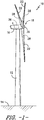
- FIG. 1 illustrates a perspective view of one embodiment of a wind turbine 10 according to the present disclosure.
- the wind turbine 10 generally includes a tower 12 extending from a support surface 14, a nacelle 16 mounted on the tower 12, and a rotor 18 coupled to the nacelle 16.
- the rotor 18 includes a rotatable hub 20 and at least one rotor blade 22 coupled to and extending outwardly from the hub 20.
- the rotor 18 includes three rotor blades 22.
- the rotor 18 may include more or less than three rotor blades 22.
- Each rotor blade 22 may be spaced about the hub 20 to facilitate rotation of the rotor 18 to enable kinetic energy to be transferred from the wind into usable mechanical energy, and subsequently, electrical energy.
- the hub 20 may be rotatably coupled to an electric generator 24 ( FIG. 2 ) positioned within the nacelle 16 to permit electrical energy to be produced.
- the wind turbine 10 may also include a wind turbine controller 26 centralized within the nacelle 16.
- the controller 26 may be located within any other component of the wind turbine 10 or at a location outside the wind turbine.
- the controller 26 may be communicatively coupled to any number of the components of the wind turbine 10 in order to control the components.
- the controller 26 may include a computer or other suitable processing unit.
- the controller 26 may include suitable computer-readable instructions that, when implemented, configure the controller 26 to perform various different functions, such as receiving, transmitting and/or executing wind turbine control signals.
- the wind turbine 10 includes the generator 24 housed within the nacelle 16, which is coupled to the rotor 18 for producing electrical power from the rotational energy generated by the rotor 18.
- the rotor 18 may include a rotor shaft 34 coupled to the hub 20 for rotation therewith.
- the rotor shaft 34 may, in turn, be rotatably coupled to a generator shaft 36 of the generator 24 through a gearbox 38 connected to a bedplate support frame 48 by a torque support 50.
- the rotor shaft 34 may provide a low speed, high torque input to the gearbox 38 in response to rotation of the rotor blades 22 and the hub 20.
- the gearbox 38 may then be configured to convert the low speed, high torque input to a high speed, low torque output to drive the generator shaft 36 and, thus, the generator 24.
- Each rotor blade 22 may also include a pitch adjustment mechanism 32 configured to rotate each rotor blade 22 about its pitch axis 28.
- each pitch adjustment mechanism 32 may include a pitch drive motor 40 (e.g., any suitable electric, hydraulic, or pneumatic motor), a pitch drive gearbox 42, and a pitch drive pinion 44.
- the pitch drive motor 40 may be coupled to the pitch drive gearbox 42 so that the pitch drive motor 40 imparts mechanical force to the pitch drive gearbox 42.
- the pitch drive gearbox 42 may be coupled to the pitch drive pinion 44 for rotation therewith.
- the pitch drive pinion 44 may, in turn, be in rotational engagement with a pitch bearing 46 coupled between the hub 20 and a corresponding rotor blade 22 such that rotation of the pitch drive pinion 44 causes rotation of the pitch bearing 46.
- rotation of the pitch drive motor 40 drives the pitch drive gearbox 42 and the pitch drive pinion 44, thereby rotating the pitch bearing 46 and the rotor blade 22 about the pitch axis 28.
- the wind turbine 10 may include one or more yaw drive mechanisms 52 communicatively coupled to the controller 26, with each yaw drive mechanism(s) 52 being configured to change the angle of the nacelle 16 relative to the wind (e.g., by engaging a yaw bearing 54 of the wind turbine 10).
- the various components within the nacelle 16 may generate excessive heat that needs to be dissipated to ambient air.
- the present disclosure is directed to a heat transfer assembly 60 for cooling off such components within the nacelle 16 (or any other location of the wind turbine 10). More specifically, as shown in FIGS. 3 and 4 , schematic diagrams of one embodiment of the heat transfer assembly 60 according to the present disclosure are illustrated. Further, as shown, the heat transfer assembly 60 includes a heat transfer apparatus 62, e.g. embedded within an outer wall 56 of the nacelle 16.
- heat transfer apparatus 62 receives the hot fluid and cools it down such that the cool or cold fluid can then be sent to a compressor/condenser 63. The compressed cooled fluid can then be recirculated back to the generator 24.
- the heat transfer apparatus 62 also includes a body 64 having a base portion 65 formed of a non-thermally conductive material 66 via an additive manufacturing process.
- the non-thermally conductive material 66 may be a thermoplastic material or a thermoset material.
- the base portion 65 of the body 64 may define a generally linear cross-sectional shape, i.e. so that the body 64 can easily be embedded or recessed with the outer wall 56 of the nacelle 16.
- the base portion 65 of the body 64 includes an inner surface 68 and an outer surface 70 having a flow path 72 extending therefrom.
- the flow path 72 may also be formed via the additive manufacturing process.
- the flow path 72 may be a simple serpentine flow path or a more complex path which is enabled by the additive manufacturing process.
- additive manufacturing generally refers to processes used to create a three-dimensional object in which layers of material are deposited or formed under computer control to create an object.
- the additive manufacturing process described herein may include, for example, big area additive manufacturing (BAAM), directed energy deposition, material jetting, or any other suitable additive manufacturing technique.
- BAAM big area additive manufacturing
- directed energy deposition material jetting
- material jetting material jetting
- the heat transfer apparatus 62 also includes a working fluid 74 configured to flow through the flow path 72.
- the heat transfer assembly 60 may also include a pumping device 75, such as a pump or a blower for moving the working fluid 74 through the body 64.
- the working fluid 74 described herein may be a gas or a liquid.
- the heat transfer apparatus 62 also includes a plate member 76 arranged adjacent to the flow path 72 of the body 64.
- the plate member 76 may be formed of a thermally-conductive material 78 so as to conduct heat from the working fluid 74 to ambient air 80.
- the thermally-conductive material 78 may be a metal material, such as for example, aluminum, steel, or titanium.
- the plate member 76 may have a relatively smooth cross section.
- the plate member 76 may include one or more protrusions 86 or fins to enhance a heat transfer coefficient of the heat transfer apparatus 62 and/or to minimize an overall size of the heat transfer apparatus 62.
- the heat transfer apparatus 62 may include a sealing layer 82 arranged between the body 64 and the plate member 76 so as to minimize leakage of the working fluid 74.
- the sealing layer 82 may include a sealing material 84 spaced apart along the flow path 72.
- the sealing material 84 may be, for example, a polymer, an adhesive, silicone, rubber, or any other suitable sealant.
- the heat transfer apparatus 62 may be sized to fit within a recess 58 of the outer wall 56 of the nacelle 16.
- the heat transfer apparatus 62 may extending along one of the sides of the nacelle 16.
- the heat transfer apparatus 62 may fit along a contour or edge of the outer wall 56 of the nacelle 16.
- the inner surface 68 of the body 64 may face an interior 59 of the nacelle 16, whereas the outer surface 70 of the body 64 may face the ambient air 80.
- FIG. 8 a flow diagram of one embodiment of one embodiment of a method 100 for manufacturing a heat transfer apparatus for a wind turbine 10 according to the present disclosure is illustrated.
- the method 100 will be described herein with reference to the wind turbine 10, nacelle 16, and heat transfer apparatus 62 shown in FIGS. 1-7 .
- the disclosed method 100 may be implemented with wind turbines having any other suitable configurations.
- FIG. 8 depicts steps performed in a particular order for purposes of illustration and discussion, the methods discussed herein are not limited to any particular order or arrangement.
- steps of the methods disclosed herein can be omitted, rearranged, combined, and/or adapted in various ways without deviating from the scope of the present disclosure.
- the method 100 may include forming the base portion 65 of the body 64 of the non-thermally conductive material 66 via an additive manufacturing process. As shown at (104), the method 100 may include forming the flow path 72 on or into the outer surface 70 of the base portion 65 of the body 64 via the additive manufacturing process. As shown at (106), the method 100 may include providing the working fluid 74 within the flow path 72. As shown at (108), the method 100 may include arranging the plate member adjacent to the flow path 72 of the body 64. Further, as mentioned, the plate member 76 is formed of the thermally-conductive material 78 so as to conduct heat from the working fluid 74 to ambient air 80.
- the method 100 may further include pumping, via one or more pumps and associated piping, the working fluid 74 through or across the body 64 of the heat transfer apparatus 62, the nacelle 16, and/or the tower 12 of the wind turbine 10.
- the method 100 may also include extracting water from the ambient air via the condenser 63 and expelling the water onto the heat transfer apparatus 62.
- the heat transfer apparatus 62 provides the ability to pump water up to the nacelle 16 via passages or piping in the tower 12.
- the condenser can extract water from the air and expel the water onto the surface (plate member/fins) of the heat transfer apparatus 62, i.e.
- thermoplastic material as described herein may generally encompass a plastic material or polymer that is reversible in nature.
- thermoplastic materials typically become pliable or moldable when heated to a certain temperature and returns to a more rigid state upon cooling.
- thermoplastic materials may include amorphous thermoplastic materials and/or semi-crystalline thermoplastic materials.
- some amorphous thermoplastic materials may generally include, but are not limited to, styrenes, vinyls, cellulosics, polyesters, acrylics, polysulphones, and/or imides.
- exemplary amorphous thermoplastic materials may include polystyrene, acrylonitrile butadiene styrene (ABS), polymethyl methacrylate (PMMA), glycolised polyethylene terephthalate (PET-G), polycarbonate, polyvinyl acetate, amorphous polyamide, polyvinyl chlorides (PVC), polyvinylidene chloride, polyurethane, or any other suitable amorphous thermoplastic material.
- exemplary semi-crystalline thermoplastic materials may generally include, but are not limited to polyolefins, polyamides, fluropolymer, ethyl-methyl acrylate, polyesters, polycarbonates, and/or acetals.
- exemplary semi-crystalline thermoplastic materials may include polybutylene terephthalate (PBT), polyethylene terephthalate (PET), polypropylene, polyphenyl sulfide, polyethylene, polyamide (nylon), polyetherketone, or any other suitable semi-crystalline thermoplastic material.
- PBT polybutylene terephthalate
- PET polyethylene terephthalate
- Ppropylene polypropylene
- polyphenyl sulfide polyethylene
- polyamide nylon
- polyetherketone polyetherketone
- thermoset material as described herein may generally encompass a plastic material or polymer that is non-reversible in nature.
- thermoset materials once cured, cannot be easily remolded or returned to a liquid state.
- thermoset materials after initial forming, are generally resistant to heat, corrosion, and/or creep.
- Example thermoset materials may generally include, but are not limited to, some polyesters, some polyurethanes, esters, epoxies, or any other suitable thermoset material.
Landscapes
- Engineering & Computer Science (AREA)
- Life Sciences & Earth Sciences (AREA)
- Sustainable Development (AREA)
- Sustainable Energy (AREA)
- Chemical & Material Sciences (AREA)
- Combustion & Propulsion (AREA)
- Mechanical Engineering (AREA)
- General Engineering & Computer Science (AREA)
- Physics & Mathematics (AREA)
- Thermal Sciences (AREA)
- Power Engineering (AREA)
- Wind Motors (AREA)
Abstract
Description
- The present disclosure relates in general to wind turbines, and more particularly to a heat transfer assembly embedded in a wind turbine nacelle.
- Wind power is considered one of the cleanest, most environmentally friendly energy sources presently available, and wind turbines have gained increased attention in this regard. A modern wind turbine typically includes a tower, a generator, a gearbox, a nacelle, and one or more rotor blades. The rotor blades capture kinetic energy of wind using known foil principles. The rotor blades transmit the kinetic energy in the form of rotational energy so as to turn a shaft coupling the rotor blades to a gearbox, or if a gearbox is not used, directly to the generator. The generator then converts the mechanical energy to electrical energy that may be deployed to a utility grid.
- The nacelle typically houses the generator, the gearbox, and various other mechanical and electrical components of the wind turbine. Therefore, such components generate heat that must be cooled off during operation of the wind turbine. Cooling of hot components in wind turbines, particularly cooling of the generator in off-shore wind turbines is currently accomplished using a complex system of ducts, fans, and/or large fabricated heat exchangers. However, such systems are complex, costly, and heavy.
- Accordingly, an improved heat transfer assembly configured for cooling off components within the wind turbine nacelle and methods of manufacturing same that addresses the aforementioned issues would be welcomed in the art.
- Aspects and advantages of the invention will be set forth in part in the following description, or may be obvious from the description, or may be learned through practice of the invention.
- In one aspect, the present disclosure is directed to a nacelle for a wind turbine. The nacelle includes a housing defining an outer wall and a heat transfer assembly embedded at least partially within the outer wall of the housing. The heat transfer assembly includes a heat transfer apparatus having a body with a flow path formed in an outer surface thereof and a working fluid configured to flow through the flow path. The heat transfer apparatus also includes a plate member arranged adjacent to the flow path of the body. As such, the plate member and the outer wall of the housing of the nacelle are configured to conduct heat from the working fluid to ambient air.
- In one embodiment, the body of the heat transfer apparatus may be formed via at least one of an additive manufacturing process or injection molding. For example, in such embodiments, the additive manufacturing process may include big area additive manufacturing (BAAM), directed energy deposition, or material jetting.
- In another embodiment, the body may be formed of a non-thermally conductive material. In such embodiments, the non-thermally conductive material may include a resin material, a ceramic material, or a low-conductivity material. More specifically, in certain embodiments, the resin material may include a thermoplastic material or a thermoset material.
- In further embodiments, the plate member may be formed of a thermally-conductive material so as to conduct the heat from the working fluid to the ambient air. In such embodiments, the thermally-conductive material may include a metal material. In addition, the working fluid may include a fluid or a gas.
- In particular embodiments, the heat transfer apparatus may be sized to fit within a recess of the outer wall of the nacelle of the wind turbine or to fit along a contour of a surface of the nacelle. In another embodiment, an inner surface of the body may face an interior of the nacelle, whereas the outer surface of the body may face the ambient air.
- In additional embodiments, the heat transfer apparatus may also include a sealing layer arranged between the body and the plate member so as to minimize leakage of the working fluid. In another embodiment, the plate member may further include one or more protrusions so as to enhance a heat transfer coefficient of the heat transfer apparatus and to minimize an overall size of the heat transfer apparatus.
- In several embodiments, the heat transfer apparatus may also include a pump, piping, or a blower for moving the working fluid through the body of the heat transfer apparatus and/or through the wind turbine.
- In another aspect, the present disclosure is directed to a heat transfer assembly for a wind turbine. The heat transfer assembly includes a heat transfer apparatus having a body formed of a non-thermally conductive material via an additive manufacturing process. The body also a flow path formed in an outer surface thereof via the additive manufacturing process. The heat transfer apparatus further includes a working fluid configured to flow through the flow path and a plate member arranged adjacent to the flow path of the body. The plate member is formed of a thermally-conductive material so as to conduct heat from the working fluid to ambient air. It should also be understood that the heat transfer apparatus may further include any of the additional features described herein.
- In yet another aspect, the present disclosure is directed to a method for manufacturing a heat transfer apparatus for a wind turbine. The method includes forming a base portion of a body of a non-thermally conductive material via an additive manufacturing process. The method also includes forming a flow path on an outer surface of the base portion of the body via the additive manufacturing process. Further, the method includes providing a working fluid within the flow path. Moreover, the method includes arranging a plate member adjacent to the flow path of the body. As such, the plate member is formed of a thermally-conductive material so as to conduct heat from the working fluid to ambient air.
- In one embodiment, the method may further include pumping, via one or more pumps and associated piping, the working fluid through or across at least one the body of the heat transfer apparatus, the nacelle, or a tower of the wind turbine. In another embodiment, the method may also include extracting water from the ambient air via a condenser and expelling the water onto the heat transfer apparatus. It should also be understood that the method may further include any of the additional steps and/or features described herein.
- These and other features, aspects and advantages of the present invention will become better understood with reference to the following description and appended claims. The accompanying drawings, which are incorporated in and constitute a part of this specification, illustrate embodiments of the invention and, together with the description, serve to explain the principles of the invention.
- A full and enabling disclosure of the present invention, including the best mode thereof, directed to one of ordinary skill in the art, is set forth in the specification, which makes reference to the appended figures, in which:
-
FIG. 1 illustrates a perspective view of one embodiment of a wind turbine according to the present disclosure; -
FIG. 2 illustrates a detailed, internal view of one embodiment of a nacelle of a wind turbine according to the present disclosure; -
FIG. 3 illustrates a schematic diagram of one embodiment of a heat transfer assembly for a wind turbine nacelle according to the present disclosure; -
FIG. 4 illustrates a cross-sectional view of one embodiment of a heat transfer apparatus of a heat transfer assembly for a wind turbine nacelle according to the present disclosure; -
FIG. 5 illustrates an exploded, perspective view of one embodiment of a heat transfer apparatus of a heat transfer assembly for a wind turbine nacelle according to the present disclosure; -
FIG. 6 illustrates a perspective view of one embodiment of nacelle of a wind turbine according to the present disclosure, particularly illustrating a heat transfer apparatus of a heat transfer assembly embedded lengthwise within multiple sides of an outer wall of the nacelle; -
FIG. 7 illustrates a perspective view of one embodiment of nacelle of a wind turbine according to the present disclosure, particularly illustrating a heat transfer apparatus of a heat transfer assembly embedded around the outer wall of the nacelle; and -
FIG. 8 illustrates a flow chart of one embodiment of a method for manufacturing a heat transfer apparatus for a wind turbine according to the present disclosure. - Reference now will be made in detail to embodiments of the invention, one or more examples of which are illustrated in the drawings. Each example is provided by way of explanation of the invention, not limitation of the invention. In fact, it will be apparent to those skilled in the art that various modifications and variations can be made in the present invention without departing from the scope or spirit of the invention. For instance, features illustrated or described as part of one embodiment can be used with another embodiment to yield a still further embodiment. Thus, it is intended that the present invention covers such modifications and variations as come within the scope of the appended claims and their equivalents.
- Referring now to the drawings,
FIG. 1 illustrates a perspective view of one embodiment of awind turbine 10 according to the present disclosure. As shown, thewind turbine 10 generally includes atower 12 extending from asupport surface 14, anacelle 16 mounted on thetower 12, and arotor 18 coupled to thenacelle 16. Therotor 18 includes arotatable hub 20 and at least onerotor blade 22 coupled to and extending outwardly from thehub 20. For example, in the illustrated embodiment, therotor 18 includes threerotor blades 22. However, in an alternative embodiment, therotor 18 may include more or less than threerotor blades 22. Eachrotor blade 22 may be spaced about thehub 20 to facilitate rotation of therotor 18 to enable kinetic energy to be transferred from the wind into usable mechanical energy, and subsequently, electrical energy. For instance, thehub 20 may be rotatably coupled to an electric generator 24 (FIG. 2 ) positioned within thenacelle 16 to permit electrical energy to be produced. - The
wind turbine 10 may also include awind turbine controller 26 centralized within thenacelle 16. However, in other embodiments, thecontroller 26 may be located within any other component of thewind turbine 10 or at a location outside the wind turbine. Further, thecontroller 26 may be communicatively coupled to any number of the components of thewind turbine 10 in order to control the components. As such, thecontroller 26 may include a computer or other suitable processing unit. Thus, in several embodiments, thecontroller 26 may include suitable computer-readable instructions that, when implemented, configure thecontroller 26 to perform various different functions, such as receiving, transmitting and/or executing wind turbine control signals. - Referring now to
FIG. 2 , a simplified, internal view of one embodiment of thenacelle 16 of thewind turbine 10 shown inFIG. 1 is illustrated. As shown, thewind turbine 10 includes thegenerator 24 housed within thenacelle 16, which is coupled to therotor 18 for producing electrical power from the rotational energy generated by therotor 18. For example, as shown, therotor 18 may include arotor shaft 34 coupled to thehub 20 for rotation therewith. Therotor shaft 34 may, in turn, be rotatably coupled to agenerator shaft 36 of thegenerator 24 through agearbox 38 connected to abedplate support frame 48 by atorque support 50. As is generally understood, therotor shaft 34 may provide a low speed, high torque input to thegearbox 38 in response to rotation of therotor blades 22 and thehub 20. Thegearbox 38 may then be configured to convert the low speed, high torque input to a high speed, low torque output to drive thegenerator shaft 36 and, thus, thegenerator 24. - Each
rotor blade 22 may also include apitch adjustment mechanism 32 configured to rotate eachrotor blade 22 about itspitch axis 28. Further, eachpitch adjustment mechanism 32 may include a pitch drive motor 40 (e.g., any suitable electric, hydraulic, or pneumatic motor), apitch drive gearbox 42, and apitch drive pinion 44. In such embodiments, thepitch drive motor 40 may be coupled to thepitch drive gearbox 42 so that thepitch drive motor 40 imparts mechanical force to thepitch drive gearbox 42. Similarly, thepitch drive gearbox 42 may be coupled to thepitch drive pinion 44 for rotation therewith. Thepitch drive pinion 44 may, in turn, be in rotational engagement with a pitch bearing 46 coupled between thehub 20 and acorresponding rotor blade 22 such that rotation of thepitch drive pinion 44 causes rotation of thepitch bearing 46. Thus, in such embodiments, rotation of thepitch drive motor 40 drives thepitch drive gearbox 42 and thepitch drive pinion 44, thereby rotating the pitch bearing 46 and therotor blade 22 about thepitch axis 28. Similarly, thewind turbine 10 may include one or moreyaw drive mechanisms 52 communicatively coupled to thecontroller 26, with each yaw drive mechanism(s) 52 being configured to change the angle of thenacelle 16 relative to the wind (e.g., by engaging a yaw bearing 54 of the wind turbine 10). - The various components within the
nacelle 16 may generate excessive heat that needs to be dissipated to ambient air. As such, the present disclosure is directed to aheat transfer assembly 60 for cooling off such components within the nacelle 16 (or any other location of the wind turbine 10). More specifically, as shown inFIGS. 3 and 4 , schematic diagrams of one embodiment of theheat transfer assembly 60 according to the present disclosure are illustrated. Further, as shown, theheat transfer assembly 60 includes aheat transfer apparatus 62, e.g. embedded within anouter wall 56 of thenacelle 16. Thus, as shown in the illustrated embodiment, heat from thegenerator 24 can be removed via a hot fluid path, e.g. via a duct. Theheat transfer apparatus 62 then receives the hot fluid and cools it down such that the cool or cold fluid can then be sent to a compressor/condenser 63. The compressed cooled fluid can then be recirculated back to thegenerator 24. - Referring now particularly to
FIGS. 4 and5 , theheat transfer apparatus 62 also includes abody 64 having abase portion 65 formed of a non-thermallyconductive material 66 via an additive manufacturing process. For example, in one embodiment, the non-thermallyconductive material 66 may be a thermoplastic material or a thermoset material. Further, as shown, thebase portion 65 of thebody 64 may define a generally linear cross-sectional shape, i.e. so that thebody 64 can easily be embedded or recessed with theouter wall 56 of thenacelle 16. In addition, as shown, thebase portion 65 of thebody 64 includes aninner surface 68 and anouter surface 70 having aflow path 72 extending therefrom. In such embodiments, theflow path 72 may also be formed via the additive manufacturing process. Thus, as shown, theflow path 72 may be a simple serpentine flow path or a more complex path which is enabled by the additive manufacturing process. - As used herein, additive manufacturing generally refers to processes used to create a three-dimensional object in which layers of material are deposited or formed under computer control to create an object. Thus, in certain embodiments, the additive manufacturing process described herein may include, for example, big area additive manufacturing (BAAM), directed energy deposition, material jetting, or any other suitable additive manufacturing technique.
- Still referring to
FIG. 5 , theheat transfer apparatus 62 also includes a workingfluid 74 configured to flow through theflow path 72. In several embodiments, theheat transfer assembly 60 may also include apumping device 75, such as a pump or a blower for moving the workingfluid 74 through thebody 64. In addition, the workingfluid 74 described herein may be a gas or a liquid. Further, as shown, theheat transfer apparatus 62 also includes aplate member 76 arranged adjacent to theflow path 72 of thebody 64. Thus, as shown, theplate member 76 may be formed of a thermally-conductive material 78 so as to conduct heat from the workingfluid 74 toambient air 80. In such embodiments, the thermally-conductive material 78 may be a metal material, such as for example, aluminum, steel, or titanium. In certain embodiments, as shown inFIGS. 3 and5 , theplate member 76 may have a relatively smooth cross section. Alternatively, as shown inFIG. 4 , theplate member 76 may include one ormore protrusions 86 or fins to enhance a heat transfer coefficient of theheat transfer apparatus 62 and/or to minimize an overall size of theheat transfer apparatus 62. - Referring back to
FIG. 5 , theheat transfer apparatus 62 may include asealing layer 82 arranged between thebody 64 and theplate member 76 so as to minimize leakage of the workingfluid 74. For example, as shown, thesealing layer 82 may include a sealingmaterial 84 spaced apart along theflow path 72. In such embodiments, the sealingmaterial 84 may be, for example, a polymer, an adhesive, silicone, rubber, or any other suitable sealant. - Referring now to
FIGS. 3-4 and6-7 , theheat transfer apparatus 62 may be sized to fit within arecess 58 of theouter wall 56 of thenacelle 16. In addition, as shown inFIG. 6 , theheat transfer apparatus 62 may extending along one of the sides of thenacelle 16. Alternatively, as shown inFIG. 7 , theheat transfer apparatus 62 may fit along a contour or edge of theouter wall 56 of thenacelle 16. Thus, as shown generally inFIGS. 3-5 , theinner surface 68 of thebody 64 may face an interior 59 of thenacelle 16, whereas theouter surface 70 of thebody 64 may face theambient air 80. - Referring now to
FIG. 8 , a flow diagram of one embodiment of one embodiment of amethod 100 for manufacturing a heat transfer apparatus for awind turbine 10 according to the present disclosure is illustrated. In general, themethod 100 will be described herein with reference to thewind turbine 10,nacelle 16, andheat transfer apparatus 62 shown inFIGS. 1-7 . However, it should be appreciated that the disclosedmethod 100 may be implemented with wind turbines having any other suitable configurations. In addition, althoughFIG. 8 depicts steps performed in a particular order for purposes of illustration and discussion, the methods discussed herein are not limited to any particular order or arrangement. One skilled in the art, using the disclosures provided herein, will appreciate that various steps of the methods disclosed herein can be omitted, rearranged, combined, and/or adapted in various ways without deviating from the scope of the present disclosure. - As shown at (102), the
method 100 may include forming thebase portion 65 of thebody 64 of the non-thermallyconductive material 66 via an additive manufacturing process. As shown at (104), themethod 100 may include forming theflow path 72 on or into theouter surface 70 of thebase portion 65 of thebody 64 via the additive manufacturing process. As shown at (106), themethod 100 may include providing the workingfluid 74 within theflow path 72. As shown at (108), themethod 100 may include arranging the plate member adjacent to theflow path 72 of thebody 64. Further, as mentioned, theplate member 76 is formed of the thermally-conductive material 78 so as to conduct heat from the workingfluid 74 toambient air 80. - In one embodiment, the
method 100 may further include pumping, via one or more pumps and associated piping, the workingfluid 74 through or across thebody 64 of theheat transfer apparatus 62, thenacelle 16, and/or thetower 12 of thewind turbine 10. In another embodiment, themethod 100 may also include extracting water from the ambient air via thecondenser 63 and expelling the water onto theheat transfer apparatus 62. In other words, theheat transfer apparatus 62 provides the ability to pump water up to thenacelle 16 via passages or piping in thetower 12. In addition, the condenser can extract water from the air and expel the water onto the surface (plate member/fins) of theheat transfer apparatus 62, i.e. either periodically or constantly via a mist, pore-like orifices in the convection surface, or a steady stream of water running down the convection surface. Such water provides evaporative cooling as needed in order to temporarily enhance the heat transfer coefficient of theheat transfer apparatus 62 in times of high thermal loading (e.g. warm or hot days with high power output). - The thermoplastic material as described herein may generally encompass a plastic material or polymer that is reversible in nature. For example, thermoplastic materials typically become pliable or moldable when heated to a certain temperature and returns to a more rigid state upon cooling. Further, thermoplastic materials may include amorphous thermoplastic materials and/or semi-crystalline thermoplastic materials. For example, some amorphous thermoplastic materials may generally include, but are not limited to, styrenes, vinyls, cellulosics, polyesters, acrylics, polysulphones, and/or imides. More specifically, exemplary amorphous thermoplastic materials may include polystyrene, acrylonitrile butadiene styrene (ABS), polymethyl methacrylate (PMMA), glycolised polyethylene terephthalate (PET-G), polycarbonate, polyvinyl acetate, amorphous polyamide, polyvinyl chlorides (PVC), polyvinylidene chloride, polyurethane, or any other suitable amorphous thermoplastic material. In addition, exemplary semi-crystalline thermoplastic materials may generally include, but are not limited to polyolefins, polyamides, fluropolymer, ethyl-methyl acrylate, polyesters, polycarbonates, and/or acetals. More specifically, exemplary semi-crystalline thermoplastic materials may include polybutylene terephthalate (PBT), polyethylene terephthalate (PET), polypropylene, polyphenyl sulfide, polyethylene, polyamide (nylon), polyetherketone, or any other suitable semi-crystalline thermoplastic material.
- Further, the thermoset material as described herein may generally encompass a plastic material or polymer that is non-reversible in nature. For example, thermoset materials, once cured, cannot be easily remolded or returned to a liquid state. As such, after initial forming, thermoset materials are generally resistant to heat, corrosion, and/or creep. Example thermoset materials may generally include, but are not limited to, some polyesters, some polyurethanes, esters, epoxies, or any other suitable thermoset material.
- This written description uses examples to disclose the invention, including the best mode, and also to enable any person skilled in the art to practice the invention, including making and using any devices or systems and performing any incorporated methods. The patentable scope of the invention is defined by the claims, and may include other examples that occur to those skilled in the art.
- Various aspects of the present invention shall now be summarized in the following clauses. Where reference to a method or method step is made, the respective method or method step is preferably executed by the controller. Obviously, the embodiments of the following clauses may also be combined with further details and aspects of the previous description and the figures.
- 1. A nacelle for a wind turbine, the nacelle comprising:
- a housing defining an outer wall; and,
- a heat transfer assembly embedded at least partially within the outer wall of the housing, the heat transfer assembly comprising a heat transfer apparatus, the heat transfer apparatus comprising a body comprising a flow path formed in an outer surface thereof and a working fluid configured to flow through the flow path, the heat transfer apparatus further comprising a plate member arranged adjacent to the flow path of the body,
- wherein the plate member and the outer wall of the housing of the nacelle are configured to conduct heat from the working fluid to ambient air.
- 2. The nacelle of clause 1, wherein the body of the heat transfer apparatus is formed via at least one of an additive manufacturing process or injection molding.
- 3. The nacelle of clause 2, wherein the additive manufacturing process comprises at least one of big area additive manufacturing (BAAM), directed energy deposition, or material jetting.
- 4. The nacelle of any preceding clause, wherein the body is formed of a non-thermally conductive material.
- 5. The nacelle of clause 4, wherein the non-thermally conductive material comprises at least one of a resin material, a ceramic material, or a low-conductivity material, the resin material comprising at least one of a thermoplastic material or a thermoset material.
- 6. The nacelle of any preceding clause, wherein the plate member is formed of a thermally-conductive material so as to conduct the heat from the working fluid to the ambient air.
- 7. The nacelle of clause 6, wherein the thermally-conductive material comprises a metal material and the working fluid comprises at least one of a fluid or a gas.
- 8. The nacelle of any preceding clause, wherein the heat transfer apparatus is sized to fit within a recess of the outer wall of the nacelle of the wind turbine or to fit along a contour of a surface of the nacelle.
- 9. The nacelle of any preceding clause, wherein an inner surface of the body faces an interior of the nacelle and the outer surface of the body faces the ambient air.
- 10. The nacelle of any preceding clause, wherein the heat transfer apparatus further comprises a sealing layer arranged between the body and the plate member so as to minimize leakage of the working fluid.
- 11. The nacelle of any preceding clause, wherein the plate member comprises one or more protrusions so as to enhance a heat transfer coefficient of the heat transfer apparatus and to minimize an overall size of the heat transfer apparatus.
- 12. The nacelle of any preceding clause, further comprising at least one of a pump, piping, or a blower for moving the working fluid through the body of the heat transfer apparatus and/or through the wind turbine.
- 13. A heat transfer assembly for a wind turbine, the heat transfer assembly comprising:
a heat transfer apparatus comprising:- a body formed of a non-thermally conductive material via an additive manufacturing process, the body comprising a flow path formed in an outer surface thereof via the additive manufacturing process;
- a working fluid configured to flow through the flow path; and,
- a plate member arranged adjacent to the flow path of the body, the plate member formed of a thermally-conductive material so as to conduct heat from the working fluid to ambient air.
- 14. The heat transfer assembly of clause 13, wherein the heat transfer apparatus is sized to fit within a recess of a wall of a nacelle of the wind turbine or to fit along a contour of an exterior surface of the nacelle.
- 15. The heat transfer assembly of
clause 13 or 14, wherein an inner surface of the body faces an interior of the nacelle and the outer surface of the body faces the ambient air. - 16. The heat transfer assembly of any preceding clause 13 to 15, wherein the heat transfer apparatus further comprises a sealing layer arranged between the body and the plate member so as to minimize leakage of the working fluid.
- 17. A method for manufacturing a heat transfer apparatus for a wind turbine, the method comprising:
- forming a base portion of a body of a non-thermally conductive material via an additive manufacturing process;
- forming a flow path on an outer surface of the base portion of the body via the additive manufacturing process;
- providing a working fluid within the flow path; and,
- arranging a plate member adjacent to the flow path of the body, the plate member formed of a thermally-conductive material so as to conduct heat from the working fluid to ambient air.
- 18. The method of clause 17, wherein the additive manufacturing process comprises at least one of big area additive manufacturing (BAAM), directed energy deposition, or material jetting.
- 19. The method of
clause 17 or 18, further comprising pumping, via one or more pumps and associated piping, the working fluid through or across at least one the body of the heat transfer apparatus, the nacelle, or a tower of the wind turbine. - 20. The method of
clause 17, 18 or 19, further comprising extracting water from the ambient air via a condenser and expelling the water onto the heat transfer apparatus.
Claims (15)
- A nacelle (16) for a wind turbine (10), the nacelle (16) comprising:a housing defining an outer wall (56); and,a heat transfer assembly (60) embedded at least partially within the outer wall (56) of the housing, the heat transfer assembly (60) comprising a heat transfer apparatus (62), the heat transfer apparatus (62) comprising a body (64) comprising a flow path (72) formed in an outer surface (70) thereof and a working fluid (74) configured to flow through the flow path (72), the heat transfer apparatus (62) further comprising a plate member (76) arranged adjacent to the flow path (72) of the body (64),wherein the plate member (76) and the outer wall (56) of the housing of the nacelle (16) are configured to conduct heat from the working fluid (74) to ambient air (80).
- The nacelle (16) of claim 1, wherein the body (64) of the heat transfer apparatus (62) is formed via at least one of an additive manufacturing process or injection molding.
- The nacelle (16) of claim 2, wherein the additive manufacturing process comprises at least one of big area additive manufacturing (BAAM), directed energy deposition, or material jetting.
- The nacelle (16) of any of the preceding claims, wherein the body (64) is formed of a non-thermally conductive material (66).
- The nacelle (16) of claim 4, wherein the non-thermally conductive material (66) comprises at least one of a resin material, a ceramic material, or a low-conductivity material, the resin material comprising at least one of a thermoplastic material or a thermoset material.
- The nacelle (16) of any of the preceding claims, wherein the plate member (76) is formed of a thermally-conductive material (78) so as to conduct the heat from the working fluid (74) to the ambient air (80).
- The nacelle (16) of claim 6, wherein the thermally-conductive material (78) comprises a metal material and the working fluid (74) comprises at least one of a fluid or a gas.
- The nacelle (16) of any of the preceding claims, wherein the heat transfer apparatus (62) is sized to fit within a recess (58) of the outer wall (56) of the nacelle (16) of the wind turbine (10) or to fit along a contour of a surface of the nacelle (16).
- The nacelle (16) of any of the preceding claims, wherein an inner surface of the body (64) faces an interior of the nacelle (16) and the outer surface (70) of the body (64) faces the ambient air (80).
- The nacelle (16) of any of the preceding claims, wherein the heat transfer apparatus (62) further comprises a sealing layer arranged between the body (64) and the plate member (76) so as to minimize leakage of the working fluid (74).
- The nacelle (16) of any of the preceding claims, wherein the plate member (76) comprises one or more protrusions so as to enhance a heat transfer coefficient of the heat transfer apparatus (62) and to minimize an overall size of the heat transfer apparatus (62).
- The nacelle (16) of any of the preceding claims, further comprising at least one of a pump, piping, or a blower for moving the working fluid (74) through the body (64) of the heat transfer apparatus (62) and/or through the wind turbine (10).
- A method (100) for manufacturing a heat transfer apparatus (62) for a wind turbine (10), the method (100) comprising:forming a base portion (65) of a body (64) of a non-thermally conductive material (66) via an additive manufacturing process;forming a flow path (72) on an outer surface (70) of the base portion (65) of the body (64) via the additive manufacturing process;providing a working fluid (74) within the flow path (72); and,arranging a plate member (76) adjacent to the flow path (72) of the body (64), the plate member (76) formed of a thermally-conductive material (78) so as to conduct heat from the working fluid (74) to ambient air (80).
- The method (100) of claim 13, wherein the additive manufacturing process comprises at least one of big area additive manufacturing (BAAM), directed energy deposition, or material jetting.
- The method (100) of claim 13, further comprising pumping, via one or more pumping devices (75) and associated piping, the working fluid (74) through or across at least one the body (64) of the heat transfer apparatus (62), the nacelle (16), or a tower of the wind turbine (10).
Applications Claiming Priority (1)
| Application Number | Priority Date | Filing Date | Title |
|---|---|---|---|
| US16/223,483 US10808684B2 (en) | 2018-12-18 | 2018-12-18 | Heat transfer assembly embedded in a wind turbine nacelle |
Publications (2)
| Publication Number | Publication Date |
|---|---|
| EP3677774A1 true EP3677774A1 (en) | 2020-07-08 |
| EP3677774B1 EP3677774B1 (en) | 2024-10-09 |
Family
ID=68917650
Family Applications (1)
| Application Number | Title | Priority Date | Filing Date |
|---|---|---|---|
| EP19216595.9A Active EP3677774B1 (en) | 2018-12-18 | 2019-12-16 | Heat transfer assembly embedded in a wind turbine nacelle |
Country Status (5)
| Country | Link |
|---|---|
| US (1) | US10808684B2 (en) |
| EP (1) | EP3677774B1 (en) |
| CN (1) | CN111336074A (en) |
| ES (1) | ES3009663T3 (en) |
| PL (1) | PL3677774T3 (en) |
Families Citing this family (2)
| Publication number | Priority date | Publication date | Assignee | Title |
|---|---|---|---|---|
| CN111677638B (en) * | 2020-06-21 | 2021-07-13 | 嘉兴学院 | A built-in cooling device for wind turbines |
| EP4603701A1 (en) * | 2024-02-14 | 2025-08-20 | Wobben Properties GmbH | Wind turbine |
Citations (5)
| Publication number | Priority date | Publication date | Assignee | Title |
|---|---|---|---|---|
| WO2010026114A2 (en) * | 2008-09-02 | 2010-03-11 | Vestas Wind Systems A/S | A wind turbine nacelle comprising a heat exchanger |
| WO2012059463A2 (en) * | 2010-11-04 | 2012-05-10 | Wobben, Aloys | Wind energy installation having a synchronous generator, and slowly rotating synchronous generator |
| US20150137412A1 (en) * | 2013-11-20 | 2015-05-21 | Carl Schalansky | Method of using additive materials for production of fluid flow channels |
| US20180244127A1 (en) * | 2017-02-28 | 2018-08-30 | General Electric Company | Thermal management system and method |
| CN108518320A (en) * | 2018-03-30 | 2018-09-11 | 北京金风科创风电设备有限公司 | Converter system and wind generating set |
Family Cites Families (13)
| Publication number | Priority date | Publication date | Assignee | Title |
|---|---|---|---|---|
| CN2497214Y (en) * | 2001-05-06 | 2002-06-26 | 苏立群 | Air conditioner with condensation vaporizing, discharging and radiating device |
| US20060075758A1 (en) * | 2004-10-07 | 2006-04-13 | Tigerone Development, Llc; | Air-conditioning and heating system utilizing thermo-electric solid state devices |
| US20080063771A1 (en) * | 2006-09-12 | 2008-03-13 | Dumm Richard H | Heat exchanger unit |
| ES2656346T3 (en) | 2007-04-30 | 2018-02-26 | Vestas Wind Systems A/S | Wind turbine and method to control the temperature of fluid flowing in a first temperature control system of a wind turbine |
| US8047774B2 (en) | 2008-09-11 | 2011-11-01 | General Electric Company | System for heating and cooling wind turbine components |
| WO2011067290A1 (en) | 2009-12-01 | 2011-06-09 | Vestas Wind Systems A/S | A wind turbine nacelle comprising a heat exchanger assembly |
| JP2012012980A (en) * | 2010-06-30 | 2012-01-19 | Mitsubishi Heavy Ind Ltd | Wind power generator |
| CN202986744U (en) * | 2012-08-28 | 2013-06-12 | 上海汽车集团股份有限公司 | Vehicle radiation heating system |
| US9952004B2 (en) * | 2013-04-11 | 2018-04-24 | Solid State Cooling Systems | High efficiency thermal transfer plate |
| US10054369B2 (en) * | 2013-10-29 | 2018-08-21 | Tai-Her Yang | Adjacently-installed temperature equalizer with single side heat transferring |
| AU2017321896A1 (en) * | 2016-09-01 | 2019-04-18 | Additive Rocket Corporation | Structural heat exchanger |
| US10788269B2 (en) * | 2016-11-07 | 2020-09-29 | Wabash National, L.P. | Cooling system for mobile bulk tanks |
| US11283189B2 (en) * | 2017-05-02 | 2022-03-22 | Rogers Corporation | Connected dielectric resonator antenna array and method of making the same |
-
2018
- 2018-12-18 US US16/223,483 patent/US10808684B2/en active Active
-
2019
- 2019-12-16 EP EP19216595.9A patent/EP3677774B1/en active Active
- 2019-12-16 PL PL19216595.9T patent/PL3677774T3/en unknown
- 2019-12-16 ES ES19216595T patent/ES3009663T3/en active Active
- 2019-12-18 CN CN201911307836.5A patent/CN111336074A/en active Pending
Patent Citations (5)
| Publication number | Priority date | Publication date | Assignee | Title |
|---|---|---|---|---|
| WO2010026114A2 (en) * | 2008-09-02 | 2010-03-11 | Vestas Wind Systems A/S | A wind turbine nacelle comprising a heat exchanger |
| WO2012059463A2 (en) * | 2010-11-04 | 2012-05-10 | Wobben, Aloys | Wind energy installation having a synchronous generator, and slowly rotating synchronous generator |
| US20150137412A1 (en) * | 2013-11-20 | 2015-05-21 | Carl Schalansky | Method of using additive materials for production of fluid flow channels |
| US20180244127A1 (en) * | 2017-02-28 | 2018-08-30 | General Electric Company | Thermal management system and method |
| CN108518320A (en) * | 2018-03-30 | 2018-09-11 | 北京金风科创风电设备有限公司 | Converter system and wind generating set |
Also Published As
| Publication number | Publication date |
|---|---|
| EP3677774B1 (en) | 2024-10-09 |
| US10808684B2 (en) | 2020-10-20 |
| CN111336074A (en) | 2020-06-26 |
| US20200191125A1 (en) | 2020-06-18 |
| ES3009663T3 (en) | 2025-03-31 |
| PL3677774T3 (en) | 2025-02-24 |
Similar Documents
| Publication | Publication Date | Title |
|---|---|---|
| EP3677774B1 (en) | Heat transfer assembly embedded in a wind turbine nacelle | |
| EP3713750A2 (en) | Methods for manufacturing wind turbine rotor blade panels having printed grid structures | |
| US9802492B2 (en) | Vehicle drag reduction and electricity generation system | |
| CA3017204C (en) | Wind turbine blade having a cover plate masking hot-air exhaust for de-icing and/or anti-icing | |
| US20200088160A1 (en) | Attachment Methods for Surface Features of Wind Turbine Rotor Blades | |
| WO2008142947A1 (en) | Wind-driven generator | |
| EP3203066A1 (en) | System and method for de-icing a wind turbine rotor blade | |
| US20180076691A1 (en) | Device thermal management assembly and method | |
| ES2881194T3 (en) | Replacement Procedures for Radial Seals of Wind Turbine Main Bearings | |
| EP3713735B1 (en) | Vacuum forming mold assembly and method for creating a vacuum forming mold assembly | |
| WO2017152367A1 (en) | Efficient and safe wind power generator | |
| US10500963B2 (en) | Vehicle drag reduction and electricity generation system | |
| EP3713734A2 (en) | Vacuum forming mold assembly and associated methods | |
| CN112377377B (en) | Thermal cycle device of wind driven generator and wind driven generator | |
| EP3908748B1 (en) | Improvements relating to cooling of electrical generators in wind turbines | |
| CN219812038U (en) | Multifunctional air-cooled motor | |
| EP3992454B1 (en) | Method and system for cooling a wind turbine gearbox oil heat-exchanger | |
| CN111749859A (en) | Wind power generating set, cooling system thereof, and control method of cooling system | |
| CN223993613U (en) | Stator structure of linear motor | |
| CN219394667U (en) | Flexible direct current transmission converter based on wind power heat dissipation | |
| CN203850935U (en) | Internal heat radiation structure of motor | |
| CN221033310U (en) | Energy-saving internal combustion engine cooling water pump | |
| CN224069015U (en) | Coordination management device for various energy storage scheduling | |
| CN217944898U (en) | Heat dissipation core structure for automobile radiator | |
| CN221096734U (en) | Fan generator set device |
Legal Events
| Date | Code | Title | Description |
|---|---|---|---|
| PUAI | Public reference made under article 153(3) epc to a published international application that has entered the european phase |
Free format text: ORIGINAL CODE: 0009012 |
|
| STAA | Information on the status of an ep patent application or granted ep patent |
Free format text: STATUS: THE APPLICATION HAS BEEN PUBLISHED |
|
| AK | Designated contracting states |
Kind code of ref document: A1 Designated state(s): AL AT BE BG CH CY CZ DE DK EE ES FI FR GB GR HR HU IE IS IT LI LT LU LV MC MK MT NL NO PL PT RO RS SE SI SK SM TR |
|
| AX | Request for extension of the european patent |
Extension state: BA ME |
|
| STAA | Information on the status of an ep patent application or granted ep patent |
Free format text: STATUS: REQUEST FOR EXAMINATION WAS MADE |
|
| 17P | Request for examination filed |
Effective date: 20201210 |
|
| RBV | Designated contracting states (corrected) |
Designated state(s): AL AT BE BG CH CY CZ DE DK EE ES FI FR GB GR HR HU IE IS IT LI LT LU LV MC MK MT NL NO PL PT RO RS SE SI SK SM TR |
|
| STAA | Information on the status of an ep patent application or granted ep patent |
Free format text: STATUS: EXAMINATION IS IN PROGRESS |
|
| 17Q | First examination report despatched |
Effective date: 20220701 |
|
| P01 | Opt-out of the competence of the unified patent court (upc) registered |
Effective date: 20230529 |
|
| RAP1 | Party data changed (applicant data changed or rights of an application transferred) |
Owner name: GENERAL ELECTRIC RENOVABLES ESPANA, S.L. |
|
| GRAP | Despatch of communication of intention to grant a patent |
Free format text: ORIGINAL CODE: EPIDOSNIGR1 |
|
| STAA | Information on the status of an ep patent application or granted ep patent |
Free format text: STATUS: GRANT OF PATENT IS INTENDED |
|
| INTG | Intention to grant announced |
Effective date: 20240510 |
|
| GRAS | Grant fee paid |
Free format text: ORIGINAL CODE: EPIDOSNIGR3 |
|
| GRAA | (expected) grant |
Free format text: ORIGINAL CODE: 0009210 |
|
| STAA | Information on the status of an ep patent application or granted ep patent |
Free format text: STATUS: THE PATENT HAS BEEN GRANTED |
|
| AK | Designated contracting states |
Kind code of ref document: B1 Designated state(s): AL AT BE BG CH CY CZ DE DK EE ES FI FR GB GR HR HU IE IS IT LI LT LU LV MC MK MT NL NO PL PT RO RS SE SI SK SM TR |
|
| REG | Reference to a national code |
Ref country code: CH Ref legal event code: EP |
|
| REG | Reference to a national code |
Ref country code: DE Ref legal event code: R096 Ref document number: 602019059985 Country of ref document: DE |
|
| REG | Reference to a national code |
Ref country code: IE Ref legal event code: FG4D |
|
| REG | Reference to a national code |
Ref country code: NL Ref legal event code: FP |
|
| REG | Reference to a national code |
Ref country code: LT Ref legal event code: MG9D |
|
| REG | Reference to a national code |
Ref country code: AT Ref legal event code: MK05 Ref document number: 1730846 Country of ref document: AT Kind code of ref document: T Effective date: 20241009 |
|
| REG | Reference to a national code |
Ref country code: ES Ref legal event code: FG2A Ref document number: 3009663 Country of ref document: ES Kind code of ref document: T3 Effective date: 20250331 |
|
| PG25 | Lapsed in a contracting state [announced via postgrant information from national office to epo] |
Ref country code: HR Free format text: LAPSE BECAUSE OF FAILURE TO SUBMIT A TRANSLATION OF THE DESCRIPTION OR TO PAY THE FEE WITHIN THE PRESCRIBED TIME-LIMIT Effective date: 20241009 Ref country code: PT Free format text: LAPSE BECAUSE OF FAILURE TO SUBMIT A TRANSLATION OF THE DESCRIPTION OR TO PAY THE FEE WITHIN THE PRESCRIBED TIME-LIMIT Effective date: 20250210 Ref country code: IS Free format text: LAPSE BECAUSE OF FAILURE TO SUBMIT A TRANSLATION OF THE DESCRIPTION OR TO PAY THE FEE WITHIN THE PRESCRIBED TIME-LIMIT Effective date: 20250209 |
|
| PG25 | Lapsed in a contracting state [announced via postgrant information from national office to epo] |
Ref country code: FI Free format text: LAPSE BECAUSE OF FAILURE TO SUBMIT A TRANSLATION OF THE DESCRIPTION OR TO PAY THE FEE WITHIN THE PRESCRIBED TIME-LIMIT Effective date: 20241009 |
|
| PG25 | Lapsed in a contracting state [announced via postgrant information from national office to epo] |
Ref country code: BG Free format text: LAPSE BECAUSE OF FAILURE TO SUBMIT A TRANSLATION OF THE DESCRIPTION OR TO PAY THE FEE WITHIN THE PRESCRIBED TIME-LIMIT Effective date: 20241009 |
|
| PG25 | Lapsed in a contracting state [announced via postgrant information from national office to epo] |
Ref country code: NO Free format text: LAPSE BECAUSE OF FAILURE TO SUBMIT A TRANSLATION OF THE DESCRIPTION OR TO PAY THE FEE WITHIN THE PRESCRIBED TIME-LIMIT Effective date: 20250109 |
|
| PG25 | Lapsed in a contracting state [announced via postgrant information from national office to epo] |
Ref country code: LV Free format text: LAPSE BECAUSE OF FAILURE TO SUBMIT A TRANSLATION OF THE DESCRIPTION OR TO PAY THE FEE WITHIN THE PRESCRIBED TIME-LIMIT Effective date: 20241009 Ref country code: GR Free format text: LAPSE BECAUSE OF FAILURE TO SUBMIT A TRANSLATION OF THE DESCRIPTION OR TO PAY THE FEE WITHIN THE PRESCRIBED TIME-LIMIT Effective date: 20250110 Ref country code: AT Free format text: LAPSE BECAUSE OF FAILURE TO SUBMIT A TRANSLATION OF THE DESCRIPTION OR TO PAY THE FEE WITHIN THE PRESCRIBED TIME-LIMIT Effective date: 20241009 |
|
| PG25 | Lapsed in a contracting state [announced via postgrant information from national office to epo] |
Ref country code: RS Free format text: LAPSE BECAUSE OF FAILURE TO SUBMIT A TRANSLATION OF THE DESCRIPTION OR TO PAY THE FEE WITHIN THE PRESCRIBED TIME-LIMIT Effective date: 20250109 |
|
| PG25 | Lapsed in a contracting state [announced via postgrant information from national office to epo] |
Ref country code: SM Free format text: LAPSE BECAUSE OF FAILURE TO SUBMIT A TRANSLATION OF THE DESCRIPTION OR TO PAY THE FEE WITHIN THE PRESCRIBED TIME-LIMIT Effective date: 20241009 |
|
| PG25 | Lapsed in a contracting state [announced via postgrant information from national office to epo] |
Ref country code: MC Free format text: LAPSE BECAUSE OF FAILURE TO SUBMIT A TRANSLATION OF THE DESCRIPTION OR TO PAY THE FEE WITHIN THE PRESCRIBED TIME-LIMIT Effective date: 20241009 |
|
| PG25 | Lapsed in a contracting state [announced via postgrant information from national office to epo] |
Ref country code: DK Free format text: LAPSE BECAUSE OF FAILURE TO SUBMIT A TRANSLATION OF THE DESCRIPTION OR TO PAY THE FEE WITHIN THE PRESCRIBED TIME-LIMIT Effective date: 20241009 |
|
| REG | Reference to a national code |
Ref country code: DE Ref legal event code: R097 Ref document number: 602019059985 Country of ref document: DE |
|
| PG25 | Lapsed in a contracting state [announced via postgrant information from national office to epo] |
Ref country code: EE Free format text: LAPSE BECAUSE OF FAILURE TO SUBMIT A TRANSLATION OF THE DESCRIPTION OR TO PAY THE FEE WITHIN THE PRESCRIBED TIME-LIMIT Effective date: 20241009 |
|
| PG25 | Lapsed in a contracting state [announced via postgrant information from national office to epo] |
Ref country code: RO Free format text: LAPSE BECAUSE OF FAILURE TO SUBMIT A TRANSLATION OF THE DESCRIPTION OR TO PAY THE FEE WITHIN THE PRESCRIBED TIME-LIMIT Effective date: 20241009 |
|
| PG25 | Lapsed in a contracting state [announced via postgrant information from national office to epo] |
Ref country code: SK Free format text: LAPSE BECAUSE OF FAILURE TO SUBMIT A TRANSLATION OF THE DESCRIPTION OR TO PAY THE FEE WITHIN THE PRESCRIBED TIME-LIMIT Effective date: 20241009 |
|
| PG25 | Lapsed in a contracting state [announced via postgrant information from national office to epo] |
Ref country code: CZ Free format text: LAPSE BECAUSE OF FAILURE TO SUBMIT A TRANSLATION OF THE DESCRIPTION OR TO PAY THE FEE WITHIN THE PRESCRIBED TIME-LIMIT Effective date: 20241009 |
|
| PG25 | Lapsed in a contracting state [announced via postgrant information from national office to epo] |
Ref country code: IT Free format text: LAPSE BECAUSE OF FAILURE TO SUBMIT A TRANSLATION OF THE DESCRIPTION OR TO PAY THE FEE WITHIN THE PRESCRIBED TIME-LIMIT Effective date: 20241009 |
|
| REG | Reference to a national code |
Ref country code: CH Ref legal event code: PL |
|
| PLBE | No opposition filed within time limit |
Free format text: ORIGINAL CODE: 0009261 |
|
| STAA | Information on the status of an ep patent application or granted ep patent |
Free format text: STATUS: NO OPPOSITION FILED WITHIN TIME LIMIT |
|
| PG25 | Lapsed in a contracting state [announced via postgrant information from national office to epo] |
Ref country code: LU Free format text: LAPSE BECAUSE OF NON-PAYMENT OF DUE FEES Effective date: 20241216 |
|
| PG25 | Lapsed in a contracting state [announced via postgrant information from national office to epo] |
Ref country code: SE Free format text: LAPSE BECAUSE OF FAILURE TO SUBMIT A TRANSLATION OF THE DESCRIPTION OR TO PAY THE FEE WITHIN THE PRESCRIBED TIME-LIMIT Effective date: 20241009 |
|
| 26N | No opposition filed |
Effective date: 20250710 |
|
| REG | Reference to a national code |
Ref country code: BE Ref legal event code: MM Effective date: 20241231 |
|
| PG25 | Lapsed in a contracting state [announced via postgrant information from national office to epo] |
Ref country code: BE Free format text: LAPSE BECAUSE OF NON-PAYMENT OF DUE FEES Effective date: 20241231 |
|
| PG25 | Lapsed in a contracting state [announced via postgrant information from national office to epo] |
Ref country code: CH Free format text: LAPSE BECAUSE OF NON-PAYMENT OF DUE FEES Effective date: 20241231 |
|
| PGFP | Annual fee paid to national office [announced via postgrant information from national office to epo] |
Ref country code: NL Payment date: 20251119 Year of fee payment: 7 |
|
| PGFP | Annual fee paid to national office [announced via postgrant information from national office to epo] |
Ref country code: DE Payment date: 20251126 Year of fee payment: 7 |
|
| PGFP | Annual fee paid to national office [announced via postgrant information from national office to epo] |
Ref country code: GB Payment date: 20251119 Year of fee payment: 7 |
|
| PGFP | Annual fee paid to national office [announced via postgrant information from national office to epo] |
Ref country code: FR Payment date: 20251120 Year of fee payment: 7 |
|
| PGFP | Annual fee paid to national office [announced via postgrant information from national office to epo] |
Ref country code: IE Payment date: 20251121 Year of fee payment: 7 |
|
| PGFP | Annual fee paid to national office [announced via postgrant information from national office to epo] |
Ref country code: PL Payment date: 20251124 Year of fee payment: 7 |
|
| PGFP | Annual fee paid to national office [announced via postgrant information from national office to epo] |
Ref country code: ES Payment date: 20260102 Year of fee payment: 7 |