EP3677713A1 - Knitted fabric design system - Google Patents
Knitted fabric design system Download PDFInfo
- Publication number
- EP3677713A1 EP3677713A1 EP19218868.8A EP19218868A EP3677713A1 EP 3677713 A1 EP3677713 A1 EP 3677713A1 EP 19218868 A EP19218868 A EP 19218868A EP 3677713 A1 EP3677713 A1 EP 3677713A1
- Authority
- EP
- European Patent Office
- Prior art keywords
- knitting
- design
- stitch
- knitted fabric
- design data
- Prior art date
- Legal status (The legal status is an assumption and is not a legal conclusion. Google has not performed a legal analysis and makes no representation as to the accuracy of the status listed.)
- Granted
Links
Images



Classifications
-
- D—TEXTILES; PAPER
- D04—BRAIDING; LACE-MAKING; KNITTING; TRIMMINGS; NON-WOVEN FABRICS
- D04B—KNITTING
- D04B37/00—Auxiliary apparatus or devices for use with knitting machines
- D04B37/02—Auxiliary apparatus or devices for use with knitting machines with weft knitting machines
-
- D—TEXTILES; PAPER
- D04—BRAIDING; LACE-MAKING; KNITTING; TRIMMINGS; NON-WOVEN FABRICS
- D04B—KNITTING
- D04B15/00—Details of, or auxiliary devices incorporated in, weft knitting machines, restricted to machines of this kind
- D04B15/66—Devices for determining or controlling patterns ; Program-control arrangements
- D04B15/68—Devices for determining or controlling patterns ; Program-control arrangements characterised by the knitting instruments used
- D04B15/78—Electrical devices
-
- D—TEXTILES; PAPER
- D04—BRAIDING; LACE-MAKING; KNITTING; TRIMMINGS; NON-WOVEN FABRICS
- D04B—KNITTING
- D04B15/00—Details of, or auxiliary devices incorporated in, weft knitting machines, restricted to machines of this kind
- D04B15/66—Devices for determining or controlling patterns ; Program-control arrangements
- D04B15/68—Devices for determining or controlling patterns ; Program-control arrangements characterised by the knitting instruments used
- D04B15/70—Devices for determining or controlling patterns ; Program-control arrangements characterised by the knitting instruments used in flat-bed knitting machines
-
- G—PHYSICS
- G06—COMPUTING OR CALCULATING; COUNTING
- G06F—ELECTRIC DIGITAL DATA PROCESSING
- G06F30/00—Computer-aided design [CAD]
- G06F30/20—Design optimisation, verification or simulation
-
- G—PHYSICS
- G06—COMPUTING OR CALCULATING; COUNTING
- G06F—ELECTRIC DIGITAL DATA PROCESSING
- G06F2113/00—Details relating to the application field
- G06F2113/12—Cloth
Definitions
- the present invention relates to a knitted fabric design system for designing a knitted fabric to be knitted with a flat knitting machine.
- knitted fabric design systems for designing a knitted fabric on a monitor have been proposed (see the knit paint system disclosed in Patent Literature 1, for example).
- a user assigns knitting codes to a design sheet displayed on the monitor to design a knitted fabric.
- the design sheet is grid-shaped such that a plurality of knitting courses, each including a plurality of knitting units lined up in a lateral direction, are lined up in a vertical direction, the plurality of knitting units corresponding to the respective needles of the needle beds of a flat knitting machine.
- the knitted fabric design system generates, based on the design sheet to which the knitting codes are assigned, design data that includes information relating to positions, on the design sheet, of the knitting units and the knitting codes assigned to the positions.
- the knitted fabric design system further generates, based on the design data, knitting data according to which the flat knitting machine performs knitting.
- the knitting assist disclosed in Patent Literature 2 for example, the loop simulation disclosed in Patent Literature 3 for example, and the like have been proposed.
- the knitting assist notifies the user of the likelihood of, when knitting is performed based on design data, knitting being discontinued due to yarn breakage or the like.
- Examples of the timing at which the notification is performed include a timing at which, for example, the number of transfer performed with respect to a single stitch, the distance between adjacent stitches, and the like in the design data exceed respective acceptable values.
- the loop simulation displays, on the monitor, a simulation image of a knitted fabric to be knitted based on the design data.
- the present invention was made in view of the aforementioned circumstances, and it is an object thereof to provide a knitted fabric design system in which it is easy to grasp an overall picture, on design data, of a knitted fabric in the course of a knitting process.
- a knitted fabric design system includes:
- the display adjustment unit may be configured to perform display such that a starting stitch and a termination stitch are connected in the wale direction with a straight line on the design data.
- the display adjustment unit may be configured to display a route of movement, in a knitting width direction, of stitches that are connected in the wale direction from a starting stitch to a termination stitch on the design data.
- the derivation unit may obtain the connection information on the assumption that, before a starting end of the partial design data, virtual stitches are present over a range larger than the knitting width of the partial design data, and may delete, from the connection information, a virtual stitch for which no knitting code is set after a predetermined number of knitting courses or more.
- a connection state of stitches in a wale direction on the design data is displayed on the design sheet, and thus a user can visually check the connection state.
- the user can easily grasp an overall picture in the course of the knitting process. Accordingly, it is easy to recognize a problematic portion of the knitting process based on the design data.
- partial design data By setting virtual stitches for partial design data for knitting a part of a knitted fabric, it is possible to grasp an overall picture of the partial design data in the course of the knitting process.
- the partial design data include an extract of existing design data for knitting a knitted fabric that corresponds to formation of a structure pattern.
- a knitted fabric design system 100 shown in the functional block diagram of FIG. 1 is provided with an input unit 1, an editing unit 2, a memory 3, and a display unit 4.
- the knitted fabric design system 100 helps a user design a knitted fabric on the display unit 4, and generates knitting data according to which a flat knitting machine knits the designed knitted fabric.
- the knitted fabric design system 100 is applicable to designing knitted fabrics to be knitted using any flat knitting machine such as a two-bed flat knitting machine or a four-bed flat knitting machine.
- the knitted fabric design system 100 has a feature of displaying, on the display unit 4, a connection state of stitches in a wale direction of a designed knitted fabric so that a user can visually check the connection state. The following will describe the constituent components of the knitted fabric design system 100 in detail.
- the input unit 1 is used by the user to edit design data, and has the form of a keyboard, a mouse, a scanner, a digitizer, or the like. In the present example, the input unit 1 is used to input knitting codes to a design sheet displayed on the display unit 4.
- the design sheet displayed on the display unit 4 has frames in a grid shape such that a plurality of knitting courses, each including a plurality of knitting units lined up in a lateral direction, are lined up in a vertical direction, the plurality of knitting units corresponding to the respective needles of the needle beds of the flat knitting machine.
- a knitting unit is a cell of the frames in a grid shape (design sheet 6) indicated by dotted lines shown in FIG. 2 , and serves as a unit to which one knitting code is assigned.
- the lateral direction of this design sheet corresponds to the length direction of the needle beds (direction in which the plurality of needles arranged in parallel to each other).
- the vertical direction of the design sheet corresponds to a time axis that indicates the time when the knitting is performed.
- the vertical direction may be considered as substantially corresponding to the wale direction of a knitted fabric.
- the design sheet may also have an additional sheet in which a stitch value, a racking pitch of the needle beds, and the like are set.
- Stitch value refers to an amount by which a needle is lowered when a stitch is formed, and when the stitch value is changed, the size of the stitch will be changed.
- Riving pitch refers to an amount of relative movement of a back needle bed of the flat knitting machine with respect to a front needle bed in the longitudinal direction. Racking of the needle beds is used when, for example, a stitch is moved in a knitting width direction.
- the knitting code that is input to each knitting unit is an icon expressed so as to be able to visually distinguish a knitting operation that the flat knitting machine is to perform.
- the knitting code is expressed by, for example, a color, a numeric character, a figure, or a combination thereof.
- the knitting operation associated with a knitting code is predetermined.
- a knitting code expressed in red is defined as a knitting code that makes the flat knitting machine form a front stitch
- a knitting code expressed in green is defined as a knitting code that makes the flat knitting machine form a back stitch.
- one knitting code may also define a plurality of knitting operations. Examples thereof include a knitting code that defines knitting a front stitch, and then moving the front stitch to the opposite needle bed.
- the knitting codes are stored in a later-described reference memory 33 of the memory 3.
- the editing unit 2 has a function of generating various types of data regarding design of a knitted fabric, and can be constituted by, for example, a computer.
- This editing unit 2 includes a design data generating unit 21, a knitting data generating unit 22, a connection data generating unit 23, and a display adjustment unit 24.
- the design data generating unit 21 generates, based on the design sheet, design data that includes information relating to positions of knitting units on the design sheet, and the knitting codes assigned to the positions.
- design data is an aggregate of a plurality of knitting codes, and is data in which the order of execution of the knitting codes is defined.
- the design data generating unit 21 can also generate, based on existing design data read out from a USB memory or the like, a new design sheet in which knitting codes are arranged at several positions.
- the knitting data generating unit 22 generates, based on the design data, knitting data according to which the flat knitting machine performs knitting.
- the knitting data is a program in which actual needle operations, actual carriage movements, and an actual procedure of feeding knitting yarn, and the like are set.
- the knitting data is transmitted to the flat knitting machine via a recording medium such as a USB memory, in a wired manner, or in a wireless manner, for example.
- the knitting data may also be used to generate a simulation image of the knitted fabric.
- the connection data generating unit 23 includes a data extracting unit 23A and a derivation unit 23B, and is configured to obtain, based on the design data, a connection state of stitches that are successive in the wale direction.
- the data extracting unit 23A extracts, based on the design data, information relating to a movement path, on the needle beds, of stitches of the knitting units and to an ultimate stitch destination.
- "Ultimate stitch destination” refers to the position of a needle on which the stitch is held after the knitting operation defined by the corresponding knitting code has been executed.
- Information relating to a movement path includes the position of a needle on which a stitch is temporarily held.
- a knitting code is set that defines moving a stitch held on a needle A of a front needle bed to a needle C, which is located to the right of the needle A by two needles, of the front needle bed, the stitch will be temporarily held on a needle of a back needle bed, and then the back needle bed is racked, and the stitch is moved to the needle C of the front needle bed.
- the data extracting unit 23A extracts information indicating that the stitch has moved via the needle of the back needle bed (information relating to a movement path) and information indicating that the stitch is held on the needle C of the front needle bed (information relating to an ultimate destination), and stores the extracted pieces of information in a movement information memory 31 of the memory 3.
- the data extracting unit 23A extracts the movement information for all of the knitting units.
- the movement information includes information indicating that the stitch will not move. If, for example, a knitting code that defines forming a front stitch on an existing stitch held on the needle A of the front needle bed is set, a front stitch will be held on the needle A of the front needle bed. In this case, the ultimate stitch destination is the same needle as the needle on which the stitch was held before the knitting code was executed.
- the derivation unit 23B acquires, based on the information relating to an ultimate stitch destination out of the movement information stored in the movement information memory 31, connection information relating to the connection state of stitches that are successive in the wale direction from the starting end to the termination on the design data. If, for example, a new first stitch contiguous with the starting stitch in the wale direction is formed, the derivation unit 23B will generate information indicating that the starting stitch and the new first stitch are contiguous with each other in the wale direction.
- the derivation unit 23B traces the new first stitch to its destination based on the movement information, and if a new second stitch contiguous with this new first stitch in the wale direction is formed, the derivation unit 23B will generate information indicating that the starting stitch, the new first stitch, and the new second stitch are contiguous with each other in the wale direction.
- the derivation unit 23B repeats this operation until the termination stitch, generates connection information relating to the connection state of stitches that are successive from the starting stitch to the termination stitch in the wale direction, and stores the generated information in a connection information memory 32.
- This derivation unit 23B performs the same operation on each of the starting stitches of the design data, and generates connection information relating to the connection state of the stitches that are successive from the starting stitch in the wale direction.
- the display adjustment unit 24 causes the display unit 4 to display the design sheet that corresponds to the design data constructed in the editing unit 2. Furthermore, the display adjustment unit 24 expresses connection states of stitches in the wale direction as drawn lines based on the connection information stored in the connection information memory 32, and causes the display unit 4 to display the connection states drawn with lines so that they are superimposed on the design sheet. Examples of the line drawing include straight lines connected to each other, and symbols such as arrows lined up in a linear fashion. Furthermore, line drawing that belongs to the front needle bed and line drawing that belongs to the back needle bed may have different colors. Specific drawing modes of a connection state include the two following modes.
- FIG. 2 shows part of the design sheet 6.
- the cells of the design sheet 6 are indicated by dotted lines.
- Each knitting unit 6u is a dotted square frame, and the design sheet 6 is designed such that a plurality of knitting courses 60, each including the knitting units 6u lined up in the lateral direction, are lined up in the vertical direction.
- a loop shape input to a knitting unit 6u is a knitting code that defines forming a front stitch.
- An upward arrow is a knitting code that defines moving a stitch from the front needle bed to the back needle bed.
- An obliquely downward arrow with "2P" is a knitting code that defines moving the back needle bed by two pitches, and moving a stitch from the back needle bed to the front needle bed.
- FIG. 2 shows only knitting codes set for the front knitted fabric portion of a tubular knitted fabric, and does not show knitting codes set for the back knitted fabric portion.
- the knitting course 60 in which no knitting codes are arranged can be regarded as having knitting codes set for the back needle bed.
- starting stitches 7s and termination stitches 7e on the design data are each indicated with a rectangle, and a starting stitch 7s and a termination stitch 7e are connected by a straight line.
- the drawing mode it is easy to recognize the ultimate positions that the stitches to be knitted successively from the starting stitch 7s in the wale direction will reach. Accordingly, it is easy to find an error in knitting on the design data. For example, even if the left-most knitting code of the seventh course from the bottom in FIG. 2 is mistakenly not set, it is possible to easily recognize that there is an error in a setting of a knitting code, because the line drawn directly upward from the left-most starting stitch 7s is displayed.
- connection states of the back knitted fabric portion are also shown in FIG. 2 , it is preferable that starting stitches and termination stitches of the back knitted fabric portion be arranged to the right of the starting stitches 7s and the termination stitches 7e, and the connection states of the back knitted fabric portion be drawn by lines.
- the second drawing mode will be described with reference to FIG. 3 .
- the design sheet 6 shown in FIG. 3 is the same as that of FIG. 2 .
- routes of movement, in the knitting width direction, of stitches that are successive in the wale direction from the starting stitch 7s to the termination stitch 7e are shown.
- a position at which stitches overlap each other is indicated by a black circle. According to this drawing mode, it is possible to easily recognize a knitting portion in which yarn breakage may occur, such as a portion in which the distance between adjacent stitches is large, or a double stitch is moved.
- the memory 3 includes the movement information memory 31 in which movement information is stored, the connection information memory 32 in which connection information is stored, and the reference memory 33 in which knitting codes are stored.
- part of the memory 3 constitutes the memories 31 to 33.
- the memory 3 can, of course, store other types of information relating to design of a knitted fabric.
- the display unit 4 is used for a user to visually recognize information relating to design of a knitted fabric. Examples of information to be displayed include the above-described design sheet and the like. For example, a liquid crystal display or the like may be used as the display unit 4. If a touch panel is used as the display unit 4, the display unit 4 can serve as part of the input unit 1.
- knitted fabric design system 100 it is possible to visually recognize connection of stitches of a knitted fabric in the wale direction, as shown in FIGS. 2 and 3 . Therefore, it is possible to easily grasp an overall picture of the knitted fabric in the course of the knitting process, and it is also possible to easily find a problematic portion of the knitting process based on design data.
- Embodiment 1 has described an example in which information relating to ultimate stitch destinations is used to draw connection states of stitches in the wale direction.
- Embodiment 2 will describe an example in which connection states are drawn taking into consideration not only information relating to ultimate stitch destinations but also information relating to movement paths of stitches on the way to the ultimate destinations.
- FIG. 4 is an enlarged view of knitting units 6u of the design sheet 6.
- FIG. 4 shows a starting stitch 7s of the front knitted fabric portion and a starting stitch 8s of the back knitted fabric portion.
- Two-dot chain lines extending from the starting stitches 7s and 8s each indicate a drawing route for drawing a connection state that corresponds to the needle bed on which stitches are held.
- the shown example depicts the drawing routes of a four-bed flat knitting machine, which includes a lower front needle bed FD, a lower back needle bed BD, an upper front needle bed FU, and an upper back needle bed BU.
- the straight line of the connection state is drawn along the second drawing route from the left of the drawing that is indicated by the two-dot chain line.
- a stitch held on the lower front needle bed FD can be moved to the lower back needle bed BD or the upper back needle bed BU, but not to the upper front needle bed FU.
- a stitch held on the lower back needle bed BD can be moved to the lower front needle bed FD or the upper front needle bed FU, but not to the upper back needle bed BU.
- no stitch can be moved between the upper front needle bed FU and the upper back needle bed BU.
- connection states are drawn according to the drawing routes of FIG. 4 .
- FIGS. 5 and 6 An example in which connection states are drawn according to the drawing routes of FIG. 4 will be described with reference to FIGS. 5 and 6 .
- FIG. 5 shows an example in which a racking pitch for the back needle beds is designated in a not-shown additional sheet.
- a knitting code that defines forming a front stitch is set for the second upper knitting unit from the starting stitch 7s that is held on the lower front needle bed FD, and then a knitting code that defines moving the stitch to the upper back needle bed BU is set for the next upper knitting unit. Accordingly, the straight line that extends from the starting stitch 7s and indicates the connection state is bent to the left and is shifted to the drawing route of the upper back needle bed BU.
- the ninth knitting course 60 from the bottom includes double stitches (each indicated by a black circle) formed on the stitches that are successive, in the wale direction, from the fifth and sixth starting stitches 7s from the left.
- double stitches are moved to the upper back needle bed BU in the thirteenth knitting course 60 from the bottom and then moved to the lower front needle bed FD in the fourteenth knitting course 60 from the bottom, resulting in triple stitches. If a double stitch is moved, there is the risk that it cannot appropriately be transferred.
- the stitch connection states together with the course of movement of stitches it is possible to easily specify the position at which problems such as yarn breakage may occur.
- partial design data serving as design data
- the partial design data include an extract of existing design data, and package data.
- Package data is design data that is stored in advance in the design system and is used to knit a part of a knitted fabric. Examples thereof include package data for performing bind-off at the end of knitting, and package data for knitting a specific structure pattern.
- the derivation unit 23B shown in FIG. 1 obtains connection information of the partial design data on the assumption that, before the starting end of the partial design data, virtual stitches are present over a range larger than the knitting width of the partial design data.
- the range in which the virtual stitches are set is a range that is larger than the knitting width of the partial design data by one or more stitches to both of the right and left sides.
- the range in which the virtual stitches are set may also cover the entire width of a knitting course (that is, all of the needles of the needle beds).
- the derivation unit 23B deletes a virtual stitch for which no knitting code is set after a predetermined number of knitting courses. Specific processing examples will be described with reference to FIGS. 7(A) and (B) .
- a design sheet 6 shown in FIG. 7(A) is obtained from partial design data that is extracted from existing design data.
- the second upper course and onward of the design sheet 6 correspond to the partial design data.
- the second knitting course 60 from the bottom includes four knitting codes that define forming a front stitch
- the third knitting course 60 from the bottom includes one knitting code that defines transferring the stitch to the opposite needle bed
- the fourth knitting course 60 from the bottom includes one knitting code that defines transferring the stitch in the knitting width direction (racking and transfer to the original needle bed)
- the sixth knitting course 60 from the bottom includes three knitting codes that define forming a front stitch.
- the derivation unit 23B sets, for such partial design data, virtual stitches 9s over the entire width of the knitting course 60 on the lower side of the starting stitches of the partial design data (on the first course of the design sheet 6). Using the virtual stitches 9s as starting stitches, information relating to connection of stitches in the wale direction is generated in accordance with the procedure shown in Embodiment 1.
- the derivation unit 23B determines that information relating to a virtual stitch 9s for which no knitting code is set after a predetermined number of knitting courses 60 or more is not involved in knitting based on the partial design data, and deletes the information from the connection information (see the lower figure of FIG. 7(A) ).
- the predetermined number may be set to, for example, three or more.
- the display adjustment unit 24 may display the state of the upper figure of FIG. 7(A) and then display the state of the lower figure of FIG. 7(A) .
- the display adjustment unit 24 may display the state of the lower figure without displaying the state of the upper figure.
- the third knitting course 60 from the bottom includes one knitting code that defines transferring the stitch to the opposite needle bed
- the fourth knitting course 60 from the bottom includes one knitting code that defines transferring the stitch to the knitting width direction
- the sixth knitting course 60 from the bottom includes four knitting codes that define forming a front stitch.
- the second upper course and onward of the design sheet 6 correspond to the partial design data.
- the derivation unit 23B sets virtual stitches 9s over the entire width of the knitting course 60 on the lower side of the starting stitches of the partial design data, and generates connection information of stitches in the wale direction. Then, as shown in the middle figure of FIG.
- the derivation unit 23B deletes, from the connection information, information relating to virtual stitches 9s that are not involved in knitting, based on the partial design data.
- the derivation unit 23B of the present example also determines that, as shown in the lower figure of FIG. 7(B) , the second virtual stitch 9s from the left for which no knitting code is set until a double stitch indicated by a black point is formed is not involved in knitting, based on the partial design data, and deletes the information relating to this virtual stitch 9s from the connection information.
Landscapes
- Engineering & Computer Science (AREA)
- Textile Engineering (AREA)
- Physics & Mathematics (AREA)
- Theoretical Computer Science (AREA)
- Computer Hardware Design (AREA)
- Evolutionary Computation (AREA)
- Geometry (AREA)
- General Engineering & Computer Science (AREA)
- General Physics & Mathematics (AREA)
- Knitting Machines (AREA)
Abstract
Description
- The present invention relates to a knitted fabric design system for designing a knitted fabric to be knitted with a flat knitting machine.
- Conventionally, knitted fabric design systems for designing a knitted fabric on a monitor have been proposed (see the knit paint system disclosed in Patent Literature 1, for example). With such a knitted fabric design system, a user assigns knitting codes to a design sheet displayed on the monitor to design a knitted fabric. The design sheet is grid-shaped such that a plurality of knitting courses, each including a plurality of knitting units lined up in a lateral direction, are lined up in a vertical direction, the plurality of knitting units corresponding to the respective needles of the needle beds of a flat knitting machine. The knitted fabric design system generates, based on the design sheet to which the knitting codes are assigned, design data that includes information relating to positions, on the design sheet, of the knitting units and the knitting codes assigned to the positions. The knitted fabric design system further generates, based on the design data, knitting data according to which the flat knitting machine performs knitting.
- As a function for helping a user design a knitted fabric when using the knitted fabric design system, the knitting assist disclosed in
Patent Literature 2 for example, the loop simulation disclosed inPatent Literature 3 for example, and the like have been proposed. The knitting assist notifies the user of the likelihood of, when knitting is performed based on design data, knitting being discontinued due to yarn breakage or the like. Examples of the timing at which the notification is performed include a timing at which, for example, the number of transfer performed with respect to a single stitch, the distance between adjacent stitches, and the like in the design data exceed respective acceptable values. On the other hand, the loop simulation displays, on the monitor, a simulation image of a knitted fabric to be knitted based on the design data. -
- Patent Literature 1:
JP H07-119004A - Patent Literature 2:
WO 2009/034910A - Patent Literature 3:
JP 2005-120501A - In the conventional knitted fabric design systems, it is difficult for a user to grasp an overall picture of a knitted fabric in the course of the knitting process. For example, even if design data is used for which the knitting assist has determined that there are no problems in continuing knitting, the pattern may be disordered when the user checks the finished knitted fabric using the loop simulation. However, since it is conventionally difficult for a user to grasp an overall picture of the knitted fabric in the course of the knitting process, it is also difficult to specify which portion of the knitting process is problematic and is causing the disorder of the pattern.
- The present invention was made in view of the aforementioned circumstances, and it is an object thereof to provide a knitted fabric design system in which it is easy to grasp an overall picture, on design data, of a knitted fabric in the course of a knitting process.
- A knitted fabric design system according to an aspect of the present invention includes:
- a display unit configured to display a design sheet that is grid-shaped such that a plurality of knitting courses, each including a plurality of knitting units lined up in a lateral direction, are lined up in a vertical direction, the knitting units corresponding to respective needles of needle beds of a flat knitting machine;
- an input unit with which a user can input knitting codes to the knitting units of the design sheet; and
- a design data generating unit configured to generate, based on the design sheet to which the knitting codes are assigned, design data that includes information relating to positions, on the design sheet, of the knitting units and the knitting codes assigned to the positions,
- wherein the knitted fabric design system further includes:
- a data extracting unit configured to extract, based on the design data, movement information relating to a movement path and an ultimate destination, on the needle beds, of stitches corresponding to the knitting units;
- a derivation unit configured to obtain, based on the movement information, connection information relating to a connection state of stitches that are successive in a wale direction from a starting end to a termination on the design data; and
- a display adjustment unit configured to cause the display unit to display, based on the connection information, the connection state drawn with a line so that the connection state is superimposed on the design sheet.
- As an aspect of the knitted fabric design system of the present invention, the display adjustment unit may be configured to perform display such that a starting stitch and a termination stitch are connected in the wale direction with a straight line on the design data.
- As an aspect of the knitted fabric design system of the present invention, the display adjustment unit may be configured to display a route of movement, in a knitting width direction, of stitches that are connected in the wale direction from a starting stitch to a termination stitch on the design data.
- As an aspect of the knitted fabric design system of the present invention, if the design data is partial design data for knitting a part of a knitted fabric, the derivation unit may obtain the connection information on the assumption that, before a starting end of the partial design data, virtual stitches are present over a range larger than the knitting width of the partial design data, and may delete, from the connection information, a virtual stitch for which no knitting code is set after a predetermined number of knitting courses or more.
- According to the knitted fabric design system of the present invention, a connection state of stitches in a wale direction on the design data is displayed on the design sheet, and thus a user can visually check the connection state. By viewing connection of stitches in the wale direction, the user can easily grasp an overall picture in the course of the knitting process. Accordingly, it is easy to recognize a problematic portion of the knitting process based on the design data.
- By connecting a starting stitch and a termination stitch in the wale direction with a straight line, it is easy to recognize the ultimate destination that the stitches that are successive from the starting stitch in the wale direction will reach. Accordingly, it is easy to recognize the state of rotation of the stitches, for example. This also creates the advantage that a stitch that is not involved in knitting and is isolated, or the like can be easily found.
- By displaying, on the display unit, a route of movement of stitches in the knitting width direction, it is possible to correctly recognize which position of the knitted fabric a stitch is to be moved to in the knitting width direction. As a result, it is easy to recognize a position at which specific knitting is performed, such as a position at which the distance between adjacent stitches is large. If a position at which the distance between adjacent stitches is large can be specified, design data can be corrected so that no yarn breakage occurs. In contrast, based on a result of loop simulation, it is not possible to recognize that the distance between adjacent stitches during the knitting is large.
- By setting virtual stitches for partial design data for knitting a part of a knitted fabric, it is possible to grasp an overall picture of the partial design data in the course of the knitting process. Examples of the partial design data include an extract of existing design data for knitting a knitted fabric that corresponds to formation of a structure pattern.
-
-
FIG. 1 is a functional block diagram illustrating a knitted fabric design system according to Embodiment 1. -
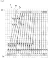
FIG. 2 is a diagram illustrating a display example of a design sheet in which connection states of stitches in a wale direction are drawn with straight lines. -
FIG. 3 is a diagram illustrating a display example of the design sheet in which routes of movement of stitches that are connected in the wale direction are drawn. -
FIG. 4 is a diagram illustrating drawing routes of connection states of stitches when a four-bed flat knitting machine is used. -
FIG. 5 is a diagram illustrating a display example of the design sheet in which routes of movement of stitches that are connected in the wale direction are drawn, according toEmbodiment 2. -
FIG. 6 is a diagram illustrating a display example of the design sheet that is different from that ofFIG. 5 . -
FIGS. 7(A) and 7(B) illustrate a procedure for drawing stitch connection states based on partial design data, according toEmbodiment 3. - Hereinafter, exemplary embodiments of a knitted fabric design system according to the present invention will be described with reference to the drawings.
- A knitted
fabric design system 100 shown in the functional block diagram ofFIG. 1 is provided with an input unit 1, anediting unit 2, amemory 3, and a display unit 4. The knittedfabric design system 100 helps a user design a knitted fabric on the display unit 4, and generates knitting data according to which a flat knitting machine knits the designed knitted fabric. The knittedfabric design system 100 is applicable to designing knitted fabrics to be knitted using any flat knitting machine such as a two-bed flat knitting machine or a four-bed flat knitting machine. The knittedfabric design system 100 has a feature of displaying, on the display unit 4, a connection state of stitches in a wale direction of a designed knitted fabric so that a user can visually check the connection state. The following will describe the constituent components of the knittedfabric design system 100 in detail. - The input unit 1 is used by the user to edit design data, and has the form of a keyboard, a mouse, a scanner, a digitizer, or the like. In the present example, the input unit 1 is used to input knitting codes to a design sheet displayed on the display unit 4.
- Note here that the design sheet displayed on the display unit 4 has frames in a grid shape such that a plurality of knitting courses, each including a plurality of knitting units lined up in a lateral direction, are lined up in a vertical direction, the plurality of knitting units corresponding to the respective needles of the needle beds of the flat knitting machine. A knitting unit is a cell of the frames in a grid shape (design sheet 6) indicated by dotted lines shown in
FIG. 2 , and serves as a unit to which one knitting code is assigned. The lateral direction of this design sheet corresponds to the length direction of the needle beds (direction in which the plurality of needles arranged in parallel to each other). On the other hand, the vertical direction of the design sheet corresponds to a time axis that indicates the time when the knitting is performed. The vertical direction may be considered as substantially corresponding to the wale direction of a knitted fabric. - The design sheet may also have an additional sheet in which a stitch value, a racking pitch of the needle beds, and the like are set. "Stitch value" refers to an amount by which a needle is lowered when a stitch is formed, and when the stitch value is changed, the size of the stitch will be changed. "Racking pitch" refers to an amount of relative movement of a back needle bed of the flat knitting machine with respect to a front needle bed in the longitudinal direction. Racking of the needle beds is used when, for example, a stitch is moved in a knitting width direction.
- The knitting code that is input to each knitting unit is an icon expressed so as to be able to visually distinguish a knitting operation that the flat knitting machine is to perform. The knitting code is expressed by, for example, a color, a numeric character, a figure, or a combination thereof. The knitting operation associated with a knitting code is predetermined. For example, a knitting code expressed in red is defined as a knitting code that makes the flat knitting machine form a front stitch, and a knitting code expressed in green is defined as a knitting code that makes the flat knitting machine form a back stitch. Of course, one knitting code may also define a plurality of knitting operations. Examples thereof include a knitting code that defines knitting a front stitch, and then moving the front stitch to the opposite needle bed. The knitting codes are stored in a later-described reference memory 33 of the
memory 3. - The
editing unit 2 has a function of generating various types of data regarding design of a knitted fabric, and can be constituted by, for example, a computer. Thisediting unit 2 includes a designdata generating unit 21, a knittingdata generating unit 22, a connectiondata generating unit 23, and adisplay adjustment unit 24. - The design
data generating unit 21 generates, based on the design sheet, design data that includes information relating to positions of knitting units on the design sheet, and the knitting codes assigned to the positions. In other words, design data is an aggregate of a plurality of knitting codes, and is data in which the order of execution of the knitting codes is defined. The designdata generating unit 21 can also generate, based on existing design data read out from a USB memory or the like, a new design sheet in which knitting codes are arranged at several positions. - The knitting
data generating unit 22 generates, based on the design data, knitting data according to which the flat knitting machine performs knitting. The knitting data is a program in which actual needle operations, actual carriage movements, and an actual procedure of feeding knitting yarn, and the like are set. The knitting data is transmitted to the flat knitting machine via a recording medium such as a USB memory, in a wired manner, or in a wireless manner, for example. The knitting data may also be used to generate a simulation image of the knitted fabric. - The connection
data generating unit 23 includes adata extracting unit 23A and aderivation unit 23B, and is configured to obtain, based on the design data, a connection state of stitches that are successive in the wale direction. Thedata extracting unit 23A extracts, based on the design data, information relating to a movement path, on the needle beds, of stitches of the knitting units and to an ultimate stitch destination. "Ultimate stitch destination" refers to the position of a needle on which the stitch is held after the knitting operation defined by the corresponding knitting code has been executed. "Information relating to a movement path" includes the position of a needle on which a stitch is temporarily held. For example, if, for a knitting unit, a knitting code is set that defines moving a stitch held on a needle A of a front needle bed to a needle C, which is located to the right of the needle A by two needles, of the front needle bed, the stitch will be temporarily held on a needle of a back needle bed, and then the back needle bed is racked, and the stitch is moved to the needle C of the front needle bed. Thedata extracting unit 23A extracts information indicating that the stitch has moved via the needle of the back needle bed (information relating to a movement path) and information indicating that the stitch is held on the needle C of the front needle bed (information relating to an ultimate destination), and stores the extracted pieces of information in amovement information memory 31 of thememory 3. Thedata extracting unit 23A extracts the movement information for all of the knitting units. - Note here that the movement information includes information indicating that the stitch will not move. If, for example, a knitting code that defines forming a front stitch on an existing stitch held on the needle A of the front needle bed is set, a front stitch will be held on the needle A of the front needle bed. In this case, the ultimate stitch destination is the same needle as the needle on which the stitch was held before the knitting code was executed.
- The
derivation unit 23B acquires, based on the information relating to an ultimate stitch destination out of the movement information stored in themovement information memory 31, connection information relating to the connection state of stitches that are successive in the wale direction from the starting end to the termination on the design data. If, for example, a new first stitch contiguous with the starting stitch in the wale direction is formed, thederivation unit 23B will generate information indicating that the starting stitch and the new first stitch are contiguous with each other in the wale direction. Furthermore, thederivation unit 23B traces the new first stitch to its destination based on the movement information, and if a new second stitch contiguous with this new first stitch in the wale direction is formed, thederivation unit 23B will generate information indicating that the starting stitch, the new first stitch, and the new second stitch are contiguous with each other in the wale direction. Thederivation unit 23B repeats this operation until the termination stitch, generates connection information relating to the connection state of stitches that are successive from the starting stitch to the termination stitch in the wale direction, and stores the generated information in aconnection information memory 32. Thisderivation unit 23B performs the same operation on each of the starting stitches of the design data, and generates connection information relating to the connection state of the stitches that are successive from the starting stitch in the wale direction. - The
display adjustment unit 24 causes the display unit 4 to display the design sheet that corresponds to the design data constructed in theediting unit 2. Furthermore, thedisplay adjustment unit 24 expresses connection states of stitches in the wale direction as drawn lines based on the connection information stored in theconnection information memory 32, and causes the display unit 4 to display the connection states drawn with lines so that they are superimposed on the design sheet. Examples of the line drawing include straight lines connected to each other, and symbols such as arrows lined up in a linear fashion. Furthermore, line drawing that belongs to the front needle bed and line drawing that belongs to the back needle bed may have different colors. Specific drawing modes of a connection state include the two following modes. - The first drawing mode will be described with reference to
FIG. 2. FIG. 2 shows part of thedesign sheet 6. InFIG. 2 , the cells of thedesign sheet 6 are indicated by dotted lines. Eachknitting unit 6u is a dotted square frame, and thedesign sheet 6 is designed such that a plurality ofknitting courses 60, each including theknitting units 6u lined up in the lateral direction, are lined up in the vertical direction. A loop shape input to aknitting unit 6u is a knitting code that defines forming a front stitch. An upward arrow is a knitting code that defines moving a stitch from the front needle bed to the back needle bed. An obliquely downward arrow with "2P" is a knitting code that defines moving the back needle bed by two pitches, and moving a stitch from the back needle bed to the front needle bed.FIG. 2 shows only knitting codes set for the front knitted fabric portion of a tubular knitted fabric, and does not show knitting codes set for the back knitted fabric portion. In other words, theknitting course 60 in which no knitting codes are arranged can be regarded as having knitting codes set for the back needle bed. - In
FIG. 2 , startingstitches 7s andtermination stitches 7e on the design data are each indicated with a rectangle, and a startingstitch 7s and atermination stitch 7e are connected by a straight line. According to the drawing mode, it is easy to recognize the ultimate positions that the stitches to be knitted successively from the startingstitch 7s in the wale direction will reach. Accordingly, it is easy to find an error in knitting on the design data. For example, even if the left-most knitting code of the seventh course from the bottom inFIG. 2 is mistakenly not set, it is possible to easily recognize that there is an error in a setting of a knitting code, because the line drawn directly upward from theleft-most starting stitch 7s is displayed. - Here, if the connection states of the back knitted fabric portion are also shown in
FIG. 2 , it is preferable that starting stitches and termination stitches of the back knitted fabric portion be arranged to the right of the starting stitches 7s and the termination stitches 7e, and the connection states of the back knitted fabric portion be drawn by lines. - The second drawing mode will be described with reference to
FIG. 3 . Thedesign sheet 6 shown inFIG. 3 is the same as that ofFIG. 2 . InFIG. 3 , on the design data, routes of movement, in the knitting width direction, of stitches that are successive in the wale direction from the startingstitch 7s to thetermination stitch 7e are shown. InFIG. 3 , a position at which stitches overlap each other is indicated by a black circle. According to this drawing mode, it is possible to easily recognize a knitting portion in which yarn breakage may occur, such as a portion in which the distance between adjacent stitches is large, or a double stitch is moved. - The
memory 3 includes themovement information memory 31 in which movement information is stored, theconnection information memory 32 in which connection information is stored, and the reference memory 33 in which knitting codes are stored. In the present example, part of thememory 3 constitutes thememories 31 to 33. Thememory 3 can, of course, store other types of information relating to design of a knitted fabric. - The display unit 4 is used for a user to visually recognize information relating to design of a knitted fabric. Examples of information to be displayed include the above-described design sheet and the like. For example, a liquid crystal display or the like may be used as the display unit 4. If a touch panel is used as the display unit 4, the display unit 4 can serve as part of the input unit 1.
- According to the above-described knitted
fabric design system 100, it is possible to visually recognize connection of stitches of a knitted fabric in the wale direction, as shown inFIGS. 2 and3 . Therefore, it is possible to easily grasp an overall picture of the knitted fabric in the course of the knitting process, and it is also possible to easily find a problematic portion of the knitting process based on design data. - Embodiment 1 has described an example in which information relating to ultimate stitch destinations is used to draw connection states of stitches in the wale direction. In contrast thereto,
Embodiment 2 will describe an example in which connection states are drawn taking into consideration not only information relating to ultimate stitch destinations but also information relating to movement paths of stitches on the way to the ultimate destinations. -
FIG. 4 is an enlarged view ofknitting units 6u of thedesign sheet 6.FIG. 4 shows a startingstitch 7s of the front knitted fabric portion and a startingstitch 8s of the back knitted fabric portion. Two-dot chain lines extending from the starting stitches 7s and 8s each indicate a drawing route for drawing a connection state that corresponds to the needle bed on which stitches are held. The shown example depicts the drawing routes of a four-bed flat knitting machine, which includes a lower front needle bed FD, a lower back needle bed BD, an upper front needle bed FU, and an upper back needle bed BU. For example, while a stitch is held on the lower front needle bed FD, the straight line of the connection state is drawn along the second drawing route from the left of the drawing that is indicated by the two-dot chain line. - Note here that, with a typical four-bed flat knitting machine, a stitch held on the lower front needle bed FD can be moved to the lower back needle bed BD or the upper back needle bed BU, but not to the upper front needle bed FU. A stitch held on the lower back needle bed BD can be moved to the lower front needle bed FD or the upper front needle bed FU, but not to the upper back needle bed BU. Furthermore, no stitch can be moved between the upper front needle bed FU and the upper back needle bed BU. In the light of such a mechanism, when, as shown in
FIG. 4 , the drawing routes of the upper back needle bed BU, the lower front needle bed FD, the lower back needle bed BD, and the upper front needle bed FU are arranged in this order from the startingstitch 7s to the startingstitch 8s, the straight lines of the connection states can be viewed very easily. An example in which connection states are drawn according to the drawing routes ofFIG. 4 will be described with reference toFIGS. 5 and6 . -
FIG. 5 shows an example in which a racking pitch for the back needle beds is designated in a not-shown additional sheet. Taking the connection state of stitches that are successive from theleft-most starting stitch 7s ofFIG. 5 as an example, a knitting code that defines forming a front stitch is set for the second upper knitting unit from the startingstitch 7s that is held on the lower front needle bed FD, and then a knitting code that defines moving the stitch to the upper back needle bed BU is set for the next upper knitting unit. Accordingly, the straight line that extends from the startingstitch 7s and indicates the connection state is bent to the left and is shifted to the drawing route of the upper back needle bed BU. For the sixth, eighth, andtenth knitting courses 60 from the bottom, knitting codes that define racking of the back needle bed are set on the additional sheet, and the straight lines that indicate the connection states are bent to the left and the right. In theeleventh knitting course 60 from the bottom, a knitting code that defines moving the stitch from the upper back needle bed BU to the lower front needle bed FD is set, and thus the straight line that indicates the connection state is shifted to the drawing route of the lower front needle bed FD, and is connected to thetermination stitch 7e. With respect to the other startingstitches 7s, stitch connection states are drawn so that a user can recognize on which needle bed stitches are held in the knitting process. When viewing the portion in the vicinity of the center ofFIG. 5 , it is clear that the distance between adjacent stitches is large. The larger the distance between stitches, the more likely that problems such as yarn breakage will occur. By drawing, in this way, the stitch connection state together with the course of movement of stitches, it is possible to easily specify the position at which problems such as yarn breakage may occur. If connection states are drawn only by connecting stitches to ultimate destinations, it is difficult to recognize the state in which the distance between adjacent stitches is large. - Furthermore, in an example shown in
FIG. 6 , theninth knitting course 60 from the bottom includes double stitches (each indicated by a black circle) formed on the stitches that are successive, in the wale direction, from the fifth and sixth starting stitches 7s from the left. These double stitches are moved to the upper back needle bed BU in thethirteenth knitting course 60 from the bottom and then moved to the lower front needle bed FD in thefourteenth knitting course 60 from the bottom, resulting in triple stitches. If a double stitch is moved, there is the risk that it cannot appropriately be transferred. By drawing, in this way, the stitch connection states together with the course of movement of stitches, it is possible to easily specify the position at which problems such as yarn breakage may occur. - There is also a demand for grasping an overall picture of partial design data, serving as design data, for knitting a part of a knitted fabric in the course of the knitting process. Examples of the partial design data include an extract of existing design data, and package data. Package data is design data that is stored in advance in the design system and is used to knit a part of a knitted fabric. Examples thereof include package data for performing bind-off at the end of knitting, and package data for knitting a specific structure pattern.
- Note here that, because partial design data does not include information relating to a knitting course to be knitted before the partial design data is knitted, and it is not clear what state the starting stitch of the partial design data is in, it is not possible to generate connection information. Accordingly, the
derivation unit 23B shown inFIG. 1 obtains connection information of the partial design data on the assumption that, before the starting end of the partial design data, virtual stitches are present over a range larger than the knitting width of the partial design data. The range in which the virtual stitches are set is a range that is larger than the knitting width of the partial design data by one or more stitches to both of the right and left sides. The range in which the virtual stitches are set may also cover the entire width of a knitting course (that is, all of the needles of the needle beds). Furthermore, thederivation unit 23B deletes a virtual stitch for which no knitting code is set after a predetermined number of knitting courses. Specific processing examples will be described with reference toFIGS. 7(A) and (B) . - A
design sheet 6 shown inFIG. 7(A) is obtained from partial design data that is extracted from existing design data. The second upper course and onward of thedesign sheet 6 correspond to the partial design data. On thisdesign sheet 6, thesecond knitting course 60 from the bottom includes four knitting codes that define forming a front stitch, thethird knitting course 60 from the bottom includes one knitting code that defines transferring the stitch to the opposite needle bed, thefourth knitting course 60 from the bottom includes one knitting code that defines transferring the stitch in the knitting width direction (racking and transfer to the original needle bed), and thesixth knitting course 60 from the bottom includes three knitting codes that define forming a front stitch. Thederivation unit 23B sets, for such partial design data,virtual stitches 9s over the entire width of theknitting course 60 on the lower side of the starting stitches of the partial design data (on the first course of the design sheet 6). Using thevirtual stitches 9s as starting stitches, information relating to connection of stitches in the wale direction is generated in accordance with the procedure shown in Embodiment 1. Here, thederivation unit 23B determines that information relating to avirtual stitch 9s for which no knitting code is set after a predetermined number ofknitting courses 60 or more is not involved in knitting based on the partial design data, and deletes the information from the connection information (see the lower figure ofFIG. 7(A) ). The predetermined number may be set to, for example, three or more. Of course, it is also possible to check all of theknitting courses 60, and identifyvirtual stitches 9s that are not involved in knitting, based on the partial design data. Thedisplay adjustment unit 24 may display the state of the upper figure ofFIG. 7(A) and then display the state of the lower figure ofFIG. 7(A) . Alternatively, thedisplay adjustment unit 24 may display the state of the lower figure without displaying the state of the upper figure. - In a
design sheet 6 show inFIG. 7(B) , thethird knitting course 60 from the bottom includes one knitting code that defines transferring the stitch to the opposite needle bed, thefourth knitting course 60 from the bottom includes one knitting code that defines transferring the stitch to the knitting width direction, and thesixth knitting course 60 from the bottom includes four knitting codes that define forming a front stitch. The second upper course and onward of thedesign sheet 6 correspond to the partial design data. Also in this example, thederivation unit 23B setsvirtual stitches 9s over the entire width of theknitting course 60 on the lower side of the starting stitches of the partial design data, and generates connection information of stitches in the wale direction. Then, as shown in the middle figure ofFIG. 7(B) , thederivation unit 23B deletes, from the connection information, information relating tovirtual stitches 9s that are not involved in knitting, based on the partial design data. Here, thederivation unit 23B of the present example also determines that, as shown in the lower figure ofFIG. 7(B) , the secondvirtual stitch 9s from the left for which no knitting code is set until a double stitch indicated by a black point is formed is not involved in knitting, based on the partial design data, and deletes the information relating to thisvirtual stitch 9s from the connection information. - With the above-described processing performed by the
derivation unit 23B, even if partial design data, which is a part of existing design data, is used, a connection state of stitches in the wale direction on the partial design data can be visually recognized. Accordingly, an overall picture of the partial design data in the course of the knitting process can be easily grasped, thus making it possible to easily improve the existing design data.
Claims (4)
- A knitted fabric design system (100) comprising:a display unit (4) configured to display a design sheet (6) that is grid-shaped such that a plurality of knitting courses (60), each including a plurality of knitting units (6u) lined up in a lateral direction, are lined up in a vertical direction, the knitting units (6u) corresponding to respective needles of needle beds of a flat knitting machine;an input unit (1) with which a user can input knitting codes to the knitting units (6u) of the design sheet (6); anda design data generating unit (21) configured to generate, based on the design sheet (6) to which the knitting codes are assigned, design data that includes information relating to positions, on the design sheet (6), of the knitting units (6u) and the knitting codes assigned to the positions,characterized in that the knitted fabric design system (100) further comprises:a data extracting unit (23A) configured to extract, based on the design data, movement information relating to a movement path and an ultimate destination, on the needle beds, of stitches corresponding to the knitting units (6u);a derivation unit (23B) configured to obtain, based on the movement information, connection information relating to a connection state of stitches that are successive in a wale direction from a starting end to a termination on the design data; anda display adjustment unit (24) configured to cause the display unit (4) to display, based on the connection information, the connection state drawn with a line so that the connection state is superimposed on the design sheet (6).
- The knitted fabric design system (100) according to claim 1,
wherein the display adjustment unit (24) is configured to perform display such that a starting stitch and a termination stitch are connected in the wale direction with a straight line on the design data. - The knitted fabric design system (100) according to claim 1,
wherein the display adjustment unit (24) is configured to display a route of movement, in a knitting width direction, of stitches that are connected in the wale direction from a starting stitch to a termination stitch on the design data. - The knitted fabric design system (100) according to any one of claims 1 to 3,
wherein, if the design data is partial design data for knitting a part of a knitted fabric, the derivation unit (23B) obtains the connection information on the assumption that, before a starting end of the partial design data, virtual stitches (9s) are present over a range larger than the knitting width of the partial design data, and deletes, from the connection information, a virtual stitch (9s) for which no knitting code is set after a predetermined number of knitting courses (60) or more.
Applications Claiming Priority (1)
| Application Number | Priority Date | Filing Date | Title |
|---|---|---|---|
| JP2018244062A JP7152302B2 (en) | 2018-12-27 | 2018-12-27 | Knitted fabric design system |
Publications (2)
| Publication Number | Publication Date |
|---|---|
| EP3677713A1 true EP3677713A1 (en) | 2020-07-08 |
| EP3677713B1 EP3677713B1 (en) | 2023-08-30 |
Family
ID=69005332
Family Applications (1)
| Application Number | Title | Priority Date | Filing Date |
|---|---|---|---|
| EP19218868.8A Active EP3677713B1 (en) | 2018-12-27 | 2019-12-20 | Knitted fabric design system |
Country Status (4)
| Country | Link |
|---|---|
| EP (1) | EP3677713B1 (en) |
| JP (1) | JP7152302B2 (en) |
| KR (1) | KR102319170B1 (en) |
| CN (1) | CN111501186B (en) |
Families Citing this family (1)
| Publication number | Priority date | Publication date | Assignee | Title |
|---|---|---|---|---|
| JP7655675B2 (en) * | 2021-06-08 | 2025-04-02 | 株式会社島精機製作所 | Method for knitting knitted fabric, knit design system, and storage medium |
Citations (5)
| Publication number | Priority date | Publication date | Assignee | Title |
|---|---|---|---|---|
| JPH07119004A (en) | 1993-08-31 | 1995-05-09 | Shima Seiki Mfg Ltd | Knit painting system and knit painting method |
| US6611730B1 (en) * | 1999-01-16 | 2003-08-26 | H. Stoll Gmbh & Co. | Device and method of designing knit products to be manufactured on a knitting machine |
| JP2005120501A (en) | 2003-10-15 | 2005-05-12 | Shima Seiki Mfg Ltd | Loop simulation apparatus and method and program thereof |
| EP2015205A1 (en) * | 2006-04-25 | 2009-01-14 | Digital Fashion Ltd. | Knitting structure model generating program, knitting structure model generating device and knitting structure model generating method |
| WO2009034910A1 (en) | 2007-09-10 | 2009-03-19 | Shima Seiki Manufacturing, Ltd. | Device and method for debugging knit design and debug program |
Family Cites Families (4)
| Publication number | Priority date | Publication date | Assignee | Title |
|---|---|---|---|---|
| WO2004022828A1 (en) * | 2002-08-30 | 2004-03-18 | Shima Seiki Manufacturing, Ltd. | Device for designing tubular knot fabric and method of designing |
| CN203212760U (en) * | 2012-09-29 | 2013-09-25 | 浙江理工大学 | Automatic bottom-starting knitting control system of flat knitting machine |
| JP6109105B2 (en) * | 2014-03-18 | 2017-04-05 | 株式会社島精機製作所 | Knit design system and knit design method |
| CN107447352A (en) * | 2016-08-26 | 2017-12-08 | 上海沙涓时装科技有限公司 | A kind of tubular 3D weaving methods of flat machine and its knit and can wear product |
-
2018
- 2018-12-27 JP JP2018244062A patent/JP7152302B2/en active Active
-
2019
- 2019-12-19 KR KR1020190170380A patent/KR102319170B1/en active Active
- 2019-12-20 EP EP19218868.8A patent/EP3677713B1/en active Active
- 2019-12-25 CN CN201911355872.9A patent/CN111501186B/en active Active
Patent Citations (5)
| Publication number | Priority date | Publication date | Assignee | Title |
|---|---|---|---|---|
| JPH07119004A (en) | 1993-08-31 | 1995-05-09 | Shima Seiki Mfg Ltd | Knit painting system and knit painting method |
| US6611730B1 (en) * | 1999-01-16 | 2003-08-26 | H. Stoll Gmbh & Co. | Device and method of designing knit products to be manufactured on a knitting machine |
| JP2005120501A (en) | 2003-10-15 | 2005-05-12 | Shima Seiki Mfg Ltd | Loop simulation apparatus and method and program thereof |
| EP2015205A1 (en) * | 2006-04-25 | 2009-01-14 | Digital Fashion Ltd. | Knitting structure model generating program, knitting structure model generating device and knitting structure model generating method |
| WO2009034910A1 (en) | 2007-09-10 | 2009-03-19 | Shima Seiki Manufacturing, Ltd. | Device and method for debugging knit design and debug program |
Non-Patent Citations (3)
| Title |
|---|
| JAMES MCCANN ET AL: "A compiler for 3D machine knitting", ACM TRANSACTIONS ON GRAPHICS, ACM, NY, US, vol. 35, no. 4, 11 July 2016 (2016-07-11), pages 1 - 11, XP058275825, ISSN: 0730-0301, DOI: 10.1145/2897824.2925940 * |
| JARED B COUNTS: "Knitting with Directed Graphs", 1 June 2018 (2018-06-01), Massachusetts Institute of Technology, pages 51 - 68, XP055691753, Retrieved from the Internet <URL:https://dspace.mit.edu/bitstream/handle/1721.1/119547/1076272960-MIT.pdf?sequence=1&isAllowed=y> [retrieved on 20200505] * |
| VIDYA NARAYANAN ET AL: "Automatic Machine Knitting of 3D Meshes", ACM TRANSACTIONS ON GRAPHICS, vol. 37, no. 3, 9 August 2018 (2018-08-09), US, pages 1 - 15, XP055691755, ISSN: 0730-0301, DOI: 10.1145/3186265 * |
Also Published As
| Publication number | Publication date |
|---|---|
| CN111501186B (en) | 2022-02-15 |
| KR102319170B1 (en) | 2021-10-28 |
| KR20200081252A (en) | 2020-07-07 |
| EP3677713B1 (en) | 2023-08-30 |
| JP2020105646A (en) | 2020-07-09 |
| JP7152302B2 (en) | 2022-10-12 |
| CN111501186A (en) | 2020-08-07 |
Similar Documents
| Publication | Publication Date | Title |
|---|---|---|
| JP2656405B2 (en) | Knit design system and method of creating knitting data | |
| US6611730B1 (en) | Device and method of designing knit products to be manufactured on a knitting machine | |
| EP2975165B1 (en) | Method for knitting cable pattern, design system of knitted fabric, and storage medium | |
| EP3677713B1 (en) | Knitted fabric design system | |
| EP1900862B1 (en) | Knit simulation device, knit simulation method, and program therefor | |
| KR101324525B1 (en) | Method and device for knit design | |
| EP2189560B1 (en) | Device and method for debugging knit design and debug program | |
| EP2492382A2 (en) | Knit design apparatus | |
| EP2492384B1 (en) | Knit design apparatus and knit design method | |
| KR102319183B1 (en) | Knit design system | |
| EP1950676B1 (en) | Border pattern designing device, designing method, and designing program | |
| EP2211283A1 (en) | Knitting design device, kintting design method and kintting design program | |
| EP4101962A1 (en) | Knitted fabric knitting method, knit designing system, and storage medium | |
| EP2492383A1 (en) | Knit designing device, designing method, and designing program | |
| CN101490326B (en) | Simulation device, simulation method and simulation program of tubular fabric | |
| EP2955258B1 (en) | Design system for knitted fabric | |
| JP6283292B2 (en) | Embroidery sewing machine control device and continuous name embroidery method |
Legal Events
| Date | Code | Title | Description |
|---|---|---|---|
| PUAI | Public reference made under article 153(3) epc to a published international application that has entered the european phase |
Free format text: ORIGINAL CODE: 0009012 |
|
| STAA | Information on the status of an ep patent application or granted ep patent |
Free format text: STATUS: THE APPLICATION HAS BEEN PUBLISHED |
|
| AK | Designated contracting states |
Kind code of ref document: A1 Designated state(s): AL AT BE BG CH CY CZ DE DK EE ES FI FR GB GR HR HU IE IS IT LI LT LU LV MC MK MT NL NO PL PT RO RS SE SI SK SM TR |
|
| AX | Request for extension of the european patent |
Extension state: BA ME |
|
| STAA | Information on the status of an ep patent application or granted ep patent |
Free format text: STATUS: REQUEST FOR EXAMINATION WAS MADE |
|
| 17P | Request for examination filed |
Effective date: 20201229 |
|
| RBV | Designated contracting states (corrected) |
Designated state(s): AL AT BE BG CH CY CZ DE DK EE ES FI FR GB GR HR HU IE IS IT LI LT LU LV MC MK MT NL NO PL PT RO RS SE SI SK SM TR |
|
| RIC1 | Information provided on ipc code assigned before grant |
Ipc: G06F 113/12 20200101ALI20220420BHEP Ipc: G06F 30/20 20200101ALI20220420BHEP Ipc: D04B 37/02 20060101AFI20220420BHEP |
|
| GRAP | Despatch of communication of intention to grant a patent |
Free format text: ORIGINAL CODE: EPIDOSNIGR1 |
|
| STAA | Information on the status of an ep patent application or granted ep patent |
Free format text: STATUS: GRANT OF PATENT IS INTENDED |
|
| INTG | Intention to grant announced |
Effective date: 20220930 |
|
| GRAJ | Information related to disapproval of communication of intention to grant by the applicant or resumption of examination proceedings by the epo deleted |
Free format text: ORIGINAL CODE: EPIDOSDIGR1 |
|
| STAA | Information on the status of an ep patent application or granted ep patent |
Free format text: STATUS: REQUEST FOR EXAMINATION WAS MADE |
|
| INTC | Intention to grant announced (deleted) | ||
| GRAP | Despatch of communication of intention to grant a patent |
Free format text: ORIGINAL CODE: EPIDOSNIGR1 |
|
| STAA | Information on the status of an ep patent application or granted ep patent |
Free format text: STATUS: GRANT OF PATENT IS INTENDED |
|
| INTG | Intention to grant announced |
Effective date: 20230321 |
|
| GRAS | Grant fee paid |
Free format text: ORIGINAL CODE: EPIDOSNIGR3 |
|
| GRAA | (expected) grant |
Free format text: ORIGINAL CODE: 0009210 |
|
| STAA | Information on the status of an ep patent application or granted ep patent |
Free format text: STATUS: THE PATENT HAS BEEN GRANTED |
|
| AK | Designated contracting states |
Kind code of ref document: B1 Designated state(s): AL AT BE BG CH CY CZ DE DK EE ES FI FR GB GR HR HU IE IS IT LI LT LU LV MC MK MT NL NO PL PT RO RS SE SI SK SM TR |
|
| REG | Reference to a national code |
Ref country code: GB Ref legal event code: FG4D |
|
| REG | Reference to a national code |
Ref country code: CH Ref legal event code: EP |
|
| REG | Reference to a national code |
Ref country code: DE Ref legal event code: R096 Ref document number: 602019036059 Country of ref document: DE |
|
| REG | Reference to a national code |
Ref country code: IE Ref legal event code: FG4D |
|
| REG | Reference to a national code |
Ref country code: LT Ref legal event code: MG9D |
|
| REG | Reference to a national code |
Ref country code: NL Ref legal event code: MP Effective date: 20230830 |
|
| REG | Reference to a national code |
Ref country code: AT Ref legal event code: MK05 Ref document number: 1605567 Country of ref document: AT Kind code of ref document: T Effective date: 20230830 |
|
| PG25 | Lapsed in a contracting state [announced via postgrant information from national office to epo] |
Ref country code: GR Free format text: LAPSE BECAUSE OF FAILURE TO SUBMIT A TRANSLATION OF THE DESCRIPTION OR TO PAY THE FEE WITHIN THE PRESCRIBED TIME-LIMIT Effective date: 20231201 |
|
| PG25 | Lapsed in a contracting state [announced via postgrant information from national office to epo] |
Ref country code: IS Free format text: LAPSE BECAUSE OF FAILURE TO SUBMIT A TRANSLATION OF THE DESCRIPTION OR TO PAY THE FEE WITHIN THE PRESCRIBED TIME-LIMIT Effective date: 20231230 |
|
| PG25 | Lapsed in a contracting state [announced via postgrant information from national office to epo] |
Ref country code: SE Free format text: LAPSE BECAUSE OF FAILURE TO SUBMIT A TRANSLATION OF THE DESCRIPTION OR TO PAY THE FEE WITHIN THE PRESCRIBED TIME-LIMIT Effective date: 20230830 Ref country code: RS Free format text: LAPSE BECAUSE OF FAILURE TO SUBMIT A TRANSLATION OF THE DESCRIPTION OR TO PAY THE FEE WITHIN THE PRESCRIBED TIME-LIMIT Effective date: 20230830 Ref country code: NO Free format text: LAPSE BECAUSE OF FAILURE TO SUBMIT A TRANSLATION OF THE DESCRIPTION OR TO PAY THE FEE WITHIN THE PRESCRIBED TIME-LIMIT Effective date: 20231130 Ref country code: LV Free format text: LAPSE BECAUSE OF FAILURE TO SUBMIT A TRANSLATION OF THE DESCRIPTION OR TO PAY THE FEE WITHIN THE PRESCRIBED TIME-LIMIT Effective date: 20230830 Ref country code: LT Free format text: LAPSE BECAUSE OF FAILURE TO SUBMIT A TRANSLATION OF THE DESCRIPTION OR TO PAY THE FEE WITHIN THE PRESCRIBED TIME-LIMIT Effective date: 20230830 Ref country code: IS Free format text: LAPSE BECAUSE OF FAILURE TO SUBMIT A TRANSLATION OF THE DESCRIPTION OR TO PAY THE FEE WITHIN THE PRESCRIBED TIME-LIMIT Effective date: 20231230 Ref country code: HR Free format text: LAPSE BECAUSE OF FAILURE TO SUBMIT A TRANSLATION OF THE DESCRIPTION OR TO PAY THE FEE WITHIN THE PRESCRIBED TIME-LIMIT Effective date: 20230830 Ref country code: GR Free format text: LAPSE BECAUSE OF FAILURE TO SUBMIT A TRANSLATION OF THE DESCRIPTION OR TO PAY THE FEE WITHIN THE PRESCRIBED TIME-LIMIT Effective date: 20231201 Ref country code: FI Free format text: LAPSE BECAUSE OF FAILURE TO SUBMIT A TRANSLATION OF THE DESCRIPTION OR TO PAY THE FEE WITHIN THE PRESCRIBED TIME-LIMIT Effective date: 20230830 Ref country code: AT Free format text: LAPSE BECAUSE OF FAILURE TO SUBMIT A TRANSLATION OF THE DESCRIPTION OR TO PAY THE FEE WITHIN THE PRESCRIBED TIME-LIMIT Effective date: 20230830 |
|
| PG25 | Lapsed in a contracting state [announced via postgrant information from national office to epo] |
Ref country code: PL Free format text: LAPSE BECAUSE OF FAILURE TO SUBMIT A TRANSLATION OF THE DESCRIPTION OR TO PAY THE FEE WITHIN THE PRESCRIBED TIME-LIMIT Effective date: 20230830 Ref country code: NL Free format text: LAPSE BECAUSE OF FAILURE TO SUBMIT A TRANSLATION OF THE DESCRIPTION OR TO PAY THE FEE WITHIN THE PRESCRIBED TIME-LIMIT Effective date: 20230830 |
|
| PG25 | Lapsed in a contracting state [announced via postgrant information from national office to epo] |
Ref country code: ES Free format text: LAPSE BECAUSE OF FAILURE TO SUBMIT A TRANSLATION OF THE DESCRIPTION OR TO PAY THE FEE WITHIN THE PRESCRIBED TIME-LIMIT Effective date: 20230830 |
|
| PG25 | Lapsed in a contracting state [announced via postgrant information from national office to epo] |
Ref country code: SM Free format text: LAPSE BECAUSE OF FAILURE TO SUBMIT A TRANSLATION OF THE DESCRIPTION OR TO PAY THE FEE WITHIN THE PRESCRIBED TIME-LIMIT Effective date: 20230830 Ref country code: RO Free format text: LAPSE BECAUSE OF FAILURE TO SUBMIT A TRANSLATION OF THE DESCRIPTION OR TO PAY THE FEE WITHIN THE PRESCRIBED TIME-LIMIT Effective date: 20230830 Ref country code: ES Free format text: LAPSE BECAUSE OF FAILURE TO SUBMIT A TRANSLATION OF THE DESCRIPTION OR TO PAY THE FEE WITHIN THE PRESCRIBED TIME-LIMIT Effective date: 20230830 Ref country code: EE Free format text: LAPSE BECAUSE OF FAILURE TO SUBMIT A TRANSLATION OF THE DESCRIPTION OR TO PAY THE FEE WITHIN THE PRESCRIBED TIME-LIMIT Effective date: 20230830 Ref country code: DK Free format text: LAPSE BECAUSE OF FAILURE TO SUBMIT A TRANSLATION OF THE DESCRIPTION OR TO PAY THE FEE WITHIN THE PRESCRIBED TIME-LIMIT Effective date: 20230830 Ref country code: CZ Free format text: LAPSE BECAUSE OF FAILURE TO SUBMIT A TRANSLATION OF THE DESCRIPTION OR TO PAY THE FEE WITHIN THE PRESCRIBED TIME-LIMIT Effective date: 20230830 Ref country code: PT Free format text: LAPSE BECAUSE OF FAILURE TO SUBMIT A TRANSLATION OF THE DESCRIPTION OR TO PAY THE FEE WITHIN THE PRESCRIBED TIME-LIMIT Effective date: 20240102 Ref country code: SK Free format text: LAPSE BECAUSE OF FAILURE TO SUBMIT A TRANSLATION OF THE DESCRIPTION OR TO PAY THE FEE WITHIN THE PRESCRIBED TIME-LIMIT Effective date: 20230830 |
|
| REG | Reference to a national code |
Ref country code: DE Ref legal event code: R097 Ref document number: 602019036059 Country of ref document: DE |
|
| PLBE | No opposition filed within time limit |
Free format text: ORIGINAL CODE: 0009261 |
|
| STAA | Information on the status of an ep patent application or granted ep patent |
Free format text: STATUS: NO OPPOSITION FILED WITHIN TIME LIMIT |
|
| PG25 | Lapsed in a contracting state [announced via postgrant information from national office to epo] |
Ref country code: SI Free format text: LAPSE BECAUSE OF FAILURE TO SUBMIT A TRANSLATION OF THE DESCRIPTION OR TO PAY THE FEE WITHIN THE PRESCRIBED TIME-LIMIT Effective date: 20230830 |
|
| REG | Reference to a national code |
Ref country code: CH Ref legal event code: PL |
|
| 26N | No opposition filed |
Effective date: 20240603 |
|
| PG25 | Lapsed in a contracting state [announced via postgrant information from national office to epo] |
Ref country code: LU Free format text: LAPSE BECAUSE OF NON-PAYMENT OF DUE FEES Effective date: 20231220 |
|
| PG25 | Lapsed in a contracting state [announced via postgrant information from national office to epo] |
Ref country code: MC Free format text: LAPSE BECAUSE OF FAILURE TO SUBMIT A TRANSLATION OF THE DESCRIPTION OR TO PAY THE FEE WITHIN THE PRESCRIBED TIME-LIMIT Effective date: 20230830 |
|
| GBPC | Gb: european patent ceased through non-payment of renewal fee |
Effective date: 20231220 |
|
| REG | Reference to a national code |
Ref country code: BE Ref legal event code: MM Effective date: 20231231 |
|
| PG25 | Lapsed in a contracting state [announced via postgrant information from national office to epo] |
Ref country code: MC Free format text: LAPSE BECAUSE OF FAILURE TO SUBMIT A TRANSLATION OF THE DESCRIPTION OR TO PAY THE FEE WITHIN THE PRESCRIBED TIME-LIMIT Effective date: 20230830 Ref country code: LU Free format text: LAPSE BECAUSE OF NON-PAYMENT OF DUE FEES Effective date: 20231220 |
|
| REG | Reference to a national code |
Ref country code: IE Ref legal event code: MM4A |
|
| PG25 | Lapsed in a contracting state [announced via postgrant information from national office to epo] |
Ref country code: IE Free format text: LAPSE BECAUSE OF NON-PAYMENT OF DUE FEES Effective date: 20231220 |
|
| PG25 | Lapsed in a contracting state [announced via postgrant information from national office to epo] |
Ref country code: GB Free format text: LAPSE BECAUSE OF NON-PAYMENT OF DUE FEES Effective date: 20231220 |
|
| PG25 | Lapsed in a contracting state [announced via postgrant information from national office to epo] |
Ref country code: BE Free format text: LAPSE BECAUSE OF NON-PAYMENT OF DUE FEES Effective date: 20231231 |
|
| PG25 | Lapsed in a contracting state [announced via postgrant information from national office to epo] |
Ref country code: FR Free format text: LAPSE BECAUSE OF NON-PAYMENT OF DUE FEES Effective date: 20231231 |
|
| PG25 | Lapsed in a contracting state [announced via postgrant information from national office to epo] |
Ref country code: CH Free format text: LAPSE BECAUSE OF NON-PAYMENT OF DUE FEES Effective date: 20231231 |
|
| PG25 | Lapsed in a contracting state [announced via postgrant information from national office to epo] |
Ref country code: IE Free format text: LAPSE BECAUSE OF NON-PAYMENT OF DUE FEES Effective date: 20231220 Ref country code: GB Free format text: LAPSE BECAUSE OF NON-PAYMENT OF DUE FEES Effective date: 20231220 Ref country code: FR Free format text: LAPSE BECAUSE OF NON-PAYMENT OF DUE FEES Effective date: 20231231 Ref country code: CH Free format text: LAPSE BECAUSE OF NON-PAYMENT OF DUE FEES Effective date: 20231231 Ref country code: BE Free format text: LAPSE BECAUSE OF NON-PAYMENT OF DUE FEES Effective date: 20231231 |
|
| PG25 | Lapsed in a contracting state [announced via postgrant information from national office to epo] |
Ref country code: BG Free format text: LAPSE BECAUSE OF FAILURE TO SUBMIT A TRANSLATION OF THE DESCRIPTION OR TO PAY THE FEE WITHIN THE PRESCRIBED TIME-LIMIT Effective date: 20230830 |
|
| PG25 | Lapsed in a contracting state [announced via postgrant information from national office to epo] |
Ref country code: BG Free format text: LAPSE BECAUSE OF FAILURE TO SUBMIT A TRANSLATION OF THE DESCRIPTION OR TO PAY THE FEE WITHIN THE PRESCRIBED TIME-LIMIT Effective date: 20230830 |
|
| PG25 | Lapsed in a contracting state [announced via postgrant information from national office to epo] |
Ref country code: CY Free format text: LAPSE BECAUSE OF FAILURE TO SUBMIT A TRANSLATION OF THE DESCRIPTION OR TO PAY THE FEE WITHIN THE PRESCRIBED TIME-LIMIT; INVALID AB INITIO Effective date: 20191220 |
|
| PG25 | Lapsed in a contracting state [announced via postgrant information from national office to epo] |
Ref country code: HU Free format text: LAPSE BECAUSE OF FAILURE TO SUBMIT A TRANSLATION OF THE DESCRIPTION OR TO PAY THE FEE WITHIN THE PRESCRIBED TIME-LIMIT; INVALID AB INITIO Effective date: 20191220 |
|
| PG25 | Lapsed in a contracting state [announced via postgrant information from national office to epo] |
Ref country code: TR Free format text: LAPSE BECAUSE OF FAILURE TO SUBMIT A TRANSLATION OF THE DESCRIPTION OR TO PAY THE FEE WITHIN THE PRESCRIBED TIME-LIMIT Effective date: 20230830 |
|
| PGFP | Annual fee paid to national office [announced via postgrant information from national office to epo] |
Ref country code: DE Payment date: 20250930 Year of fee payment: 7 |
|
| PGFP | Annual fee paid to national office [announced via postgrant information from national office to epo] |
Ref country code: IT Payment date: 20251121 Year of fee payment: 7 |