EP3677541A1 - Control system for lowering forklift lever - Google Patents
Control system for lowering forklift lever Download PDFInfo
- Publication number
- EP3677541A1 EP3677541A1 EP19218387.9A EP19218387A EP3677541A1 EP 3677541 A1 EP3677541 A1 EP 3677541A1 EP 19218387 A EP19218387 A EP 19218387A EP 3677541 A1 EP3677541 A1 EP 3677541A1
- Authority
- EP
- European Patent Office
- Prior art keywords
- load
- work lever
- weight
- current
- maximum
- Prior art date
- Legal status (The legal status is an assumption and is not a legal conclusion. Google has not performed a legal analysis and makes no representation as to the accuracy of the status listed.)
- Granted
Links
Images


Classifications
-
- B—PERFORMING OPERATIONS; TRANSPORTING
- B66—HOISTING; LIFTING; HAULING
- B66F—HOISTING, LIFTING, HAULING OR PUSHING, NOT OTHERWISE PROVIDED FOR, e.g. DEVICES WHICH APPLY A LIFTING OR PUSHING FORCE DIRECTLY TO THE SURFACE OF A LOAD
- B66F9/00—Devices for lifting or lowering bulky or heavy goods for loading or unloading purposes
- B66F9/06—Devices for lifting or lowering bulky or heavy goods for loading or unloading purposes movable, with their loads, on wheels or the like, e.g. fork-lift trucks
- B66F9/075—Constructional features or details
- B66F9/0755—Position control; Position detectors
-
- B—PERFORMING OPERATIONS; TRANSPORTING
- B66—HOISTING; LIFTING; HAULING
- B66F—HOISTING, LIFTING, HAULING OR PUSHING, NOT OTHERWISE PROVIDED FOR, e.g. DEVICES WHICH APPLY A LIFTING OR PUSHING FORCE DIRECTLY TO THE SURFACE OF A LOAD
- B66F9/00—Devices for lifting or lowering bulky or heavy goods for loading or unloading purposes
- B66F9/06—Devices for lifting or lowering bulky or heavy goods for loading or unloading purposes movable, with their loads, on wheels or the like, e.g. fork-lift trucks
- B66F9/075—Constructional features or details
- B66F9/20—Means for actuating or controlling masts, platforms, or forks
- B66F9/22—Hydraulic devices or systems
-
- B—PERFORMING OPERATIONS; TRANSPORTING
- B60—VEHICLES IN GENERAL
- B60W—CONJOINT CONTROL OF VEHICLE SUB-UNITS OF DIFFERENT TYPE OR DIFFERENT FUNCTION; CONTROL SYSTEMS SPECIALLY ADAPTED FOR HYBRID VEHICLES; ROAD VEHICLE DRIVE CONTROL SYSTEMS FOR PURPOSES NOT RELATED TO THE CONTROL OF A PARTICULAR SUB-UNIT
- B60W10/00—Conjoint control of vehicle sub-units of different type or different function
- B60W10/30—Conjoint control of vehicle sub-units of different type or different function including control of auxiliary equipment, e.g. air-conditioning compressors or oil pumps
-
- B—PERFORMING OPERATIONS; TRANSPORTING
- B66—HOISTING; LIFTING; HAULING
- B66F—HOISTING, LIFTING, HAULING OR PUSHING, NOT OTHERWISE PROVIDED FOR, e.g. DEVICES WHICH APPLY A LIFTING OR PUSHING FORCE DIRECTLY TO THE SURFACE OF A LOAD
- B66F9/00—Devices for lifting or lowering bulky or heavy goods for loading or unloading purposes
- B66F9/06—Devices for lifting or lowering bulky or heavy goods for loading or unloading purposes movable, with their loads, on wheels or the like, e.g. fork-lift trucks
- B66F9/075—Constructional features or details
- B66F9/12—Platforms; Forks; Other load supporting or gripping members
-
- F—MECHANICAL ENGINEERING; LIGHTING; HEATING; WEAPONS; BLASTING
- F15—FLUID-PRESSURE ACTUATORS; HYDRAULICS OR PNEUMATICS IN GENERAL
- F15B—SYSTEMS ACTING BY MEANS OF FLUIDS IN GENERAL; FLUID-PRESSURE ACTUATORS, e.g. SERVOMOTORS; DETAILS OF FLUID-PRESSURE SYSTEMS, NOT OTHERWISE PROVIDED FOR
- F15B11/00—Servomotor systems without provision for follow-up action; Circuits therefor
- F15B11/02—Systems essentially incorporating special features for controlling the speed or actuating force of an output member
- F15B11/04—Systems essentially incorporating special features for controlling the speed or actuating force of an output member for controlling the speed
- F15B11/05—Systems essentially incorporating special features for controlling the speed or actuating force of an output member for controlling the speed specially adapted to maintain constant speed, e.g. pressure-compensated, load-responsive
-
- B—PERFORMING OPERATIONS; TRANSPORTING
- B60—VEHICLES IN GENERAL
- B60W—CONJOINT CONTROL OF VEHICLE SUB-UNITS OF DIFFERENT TYPE OR DIFFERENT FUNCTION; CONTROL SYSTEMS SPECIALLY ADAPTED FOR HYBRID VEHICLES; ROAD VEHICLE DRIVE CONTROL SYSTEMS FOR PURPOSES NOT RELATED TO THE CONTROL OF A PARTICULAR SUB-UNIT
- B60W2300/00—Indexing codes relating to the type of vehicle
- B60W2300/12—Trucks; Load vehicles
- B60W2300/121—Fork lift trucks, Clarks
Definitions
- aspects of embodiments relate to a system of controlling a lowering speed, and more particularly, to a system of controlling a speed of lowering a forklift lever which may lower the work lever of the forklift at a constant lowering speed, irrespective of a weight of a load.
- a forklift is a machine that transports loads using a hydraulic system.
- a lifting or lowering speed of a work lever which supports loads, inevitably varies depending on the weight of the load.
- the speed of lowering the work lever is proportional to a pressure of a hydraulic cylinder connected to the work lever, the lowering speed is low when there is no load, and the lowering speed is high when there is a load. Control over the lowering speed is essential since it is directly related to safety.
- FIG. 1 is a graph illustrating a lowering speed of a lever of a conventional forklift equipped with a flow regulator.
- the flow regulator merely controls the maximum speed, and since the time for reaching the maximum speed of the work lever varies depending on the weight of the load, the controllability and operability of the forklift are bound to be degraded.
- Embodiments may be directed to a system of controlling a lowering speed of a work lever of a forklift which may realize a constant amount of change in the lowering speed with respect to a valve opening area, irrespective of a weight of a load placed on the work lever, although a flow regulator is not provided.
- a system of controlling a lowering speed of a work lever of a forklift includes, a hydraulic motor connected to the work lever through a hydraulic line to transmit a power to the work lever; an electronic solenoid valve for controlling the hydraulic motor connected to the work lever; a weight sensor provided at one side of the work lever, the weight sensor measuring a weight of a load placed on the work lever and transmitting the measured value to a controller; and a controller for controlling an RPM of the hydraulic motor and a current amount of the electronic solenoid valve based on the measured value transmitted from the weight sensor.
- a constant amount of change in a lowering speed of the work lever with respect to a valve opening area is implemented, irrespective of the weight of the load placed on the work lever.
- the weight sensor may measure the weight of the load placed on the work lever, convert the weight into a load voltage, and transmit the load voltage to the controller.
- a table may be preset in the controller, the table including a maximum current under a full load condition of the load placed on the work lever and a maximum current under a no-load condition, and the controller may determine a maximum load current of the electronic solenoid valve, between the maximum current under the full load condition and the maximum current under the no-load condition, according to the weight of the load measured by the weight sensor.
- the controller may determine the maximum load current of the electronic solenoid valve based on the load voltage and the following Equation 1.
- H B ⁇ C E ⁇ D ⁇ G ⁇ D + C
- B Maximum current under full load condition
- C Maximum current under no-load condition
- D Minimum weight voltage
- E Maximum weight voltage
- G Load voltage
- a table according to a height of a work lever may be preset in the controller, and the controller may determine a valve current applied to the electronic solenoid valve, based on the determined maximum load current.
- the controller may determine the valve current based on the following Equation 2.
- I A + F 1000 ⁇ H ⁇ A
- A Minimum valve current
- D Minimum weight voltage
- H Maximum load current
- I Valve Current
- the present disclosure is configured so that a constant amount of change in a lowering speed of a work lever 11, with respect to a valve opening area, is realized, irrespective of a weight of a load placed on the work lever 11, through the use of a weight sensor 140 without using a separate expensive regulator (e.g., a check valve), thereby increasing the controllability and stability of the forklift operation.
- a separate expensive regulator e.g., a check valve
- FIG. 2 is a block diagram illustrating a system of controlling a lowering speed of the forklift lever 11 according to an embodiment of the present disclosure.
- a system of controlling a lowering speed of a work lever 11 of a forklift 10 includes a work machine operation device 110; a controller 120 for controlling an RPM of a hydraulic motor 130 and a current amount of an electronic solenoid valve 150; the hydraulic motor 130 connected to the work lever 11 through a hydraulic line to transmit a power to the work lever 11; a weight sensor 140 provided at one side of the work lever 11 of the forklift 10 to measure a weight of a load placed on the work lever 11; and the electronic solenoid valve 150 for controlling the hydraulic motor 130 connected to the work lever 11.
- the controller 120 may extract only the weight of the load from the weight sensor 140, which simultaneously measures a weight of the work lever 11 and the weight of the load.
- the weight sensor 140 measures the weight of the work lever 11 of the forklift 10, converts the weight into a load voltage G, and transmits the load voltage G to the controller 120.
- a table including a maximum current B under a full load condition and a maximum current C under a no-load condition is preset according to the weight of the load placed on the work lever 11. According to the weight of the load measured by the weight sensor 140, the controller 120 determines a maximum current H of the electronic solenoid valve 150 between the current C under the full load condition and the current B under the no-load condition.
- FIG. 3 is a graph illustrating a current map, in the controller 120, which is preset according to the weight of the load.
- a horizontal axis represents a voltage converted by the weight sensor 140 according to the weight of the load placed on the work lever 11, and a vertical axis represents a preset current corresponding to the horizontal axis.
- FIG. 4 is a graph illustrating a current change map according to a height of the work lever 11 according to an embodiment of the present disclosure.
- a horizontal axis represents a position of the work lever 11
- a vertical axis represents a current applied to the electronic solenoid valve 150.
- FIG. 4 illustrates a map which illustrates a maximum current B under the full load condition and a maximum current C under the no-load condition, according to the position of the work lever 11.
- FIG. 3 illustrates the maximum current B under the full load condition and the maximum current C under the no-load condition when the work lever 11 is at a maximum height in FIG. 4 .
- a maximum weight voltage E measured and converted by the weight sensor 140 is 4.5 V, and the maximum current (or a valve current) B under the full load condition corresponding thereto in the table is preset to 400 mA.
- the maximum weight voltage E measured and converted by the weight sensor 140 is 0.25 V, and the maximum current (or a valve current) C under the no-load condition corresponding thereto in the table is preset to 500 mA.
- the weight sensor 140 transmits, to the controller 120, the load voltage (or weight voltage) G according to the weight of the load, and the controller 120 determines the maximum load current (or a valve current) H of the electronic solenoid valve 150, based on the following Equation 1, by matching the load voltage G in the preset map.
- H B ⁇ C E ⁇ D ⁇ G ⁇ D + C
- B Maximum current under full load condition
- C Maximum current under no-load condition
- D Minimum weight voltage
- E Maximum weight voltage
- G Load voltage
- the controller 120 determines the maximum load current H based on [Equation 1] between the maximum current B under the full load condition and the maximum current C under the no-load condition, and the maximum load current H is illustrated in FIG. 3 .
- a map according to a height F of the work lever 11 is preset in the controller 120, and a valve current I is obtained by using the maximum load current H determined in the controller 120.
- the valve current I has a current value applied to the electronic solenoid valve 150, and in detail, the controller 120 may obtain the valve current I based on the following [Equation 2].
- I A + F 1000 ⁇ H ⁇ A
- F Height of the work lever 11
- H Maximum load current I: Valve Current
- FIG. 5 is a graph illustrating a lowering speed of a lever of a forklift according to an embodiment of the present disclosure.
- a relatively low cost weight sensor may be used to measure the weight of the load into a voltage signal and then a signal of the electronic solenoid valve may be controlled based on the voltage signal, so as to realize a uniform change in the lowering speed of the work lever 11 with respect to a valve opening area. Accordingly, a certain operability may be provided during the lowering operation of the work lever 11, and the cost may be reduced such that the economic efficiency may be improved.
- a constant amount of change in the speed of lowering the work lever, with respect to a valve opening area may be achieved.
- the flow regulator is not provided, a constant amount of change in the lowering speed with respect to a valve opening area may be realized at any point between the full load and the no-load conditions. Accordingly, the present disclosure may have a certain controllability, thereby increasing the stability of the forklift.
Landscapes
- Engineering & Computer Science (AREA)
- Transportation (AREA)
- Structural Engineering (AREA)
- Mechanical Engineering (AREA)
- Life Sciences & Earth Sciences (AREA)
- Civil Engineering (AREA)
- Geology (AREA)
- Chemical & Material Sciences (AREA)
- Combustion & Propulsion (AREA)
- Physics & Mathematics (AREA)
- Fluid Mechanics (AREA)
- General Engineering & Computer Science (AREA)
- Forklifts And Lifting Vehicles (AREA)
Abstract
Description
- This application claims priority to and the benefit of Korean Patent Application No.
10-2018-0166139, filed on December 20, 2018 - Aspects of embodiments relate to a system of controlling a lowering speed, and more particularly, to a system of controlling a speed of lowering a forklift lever which may lower the work lever of the forklift at a constant lowering speed, irrespective of a weight of a load.
- A forklift is a machine that transports loads using a hydraulic system. In such a case, due to the characteristics of the hydraulic system, a lifting or lowering speed of a work lever, which supports loads, inevitably varies depending on the weight of the load. In particular, since the speed of lowering the work lever is proportional to a pressure of a hydraulic cylinder connected to the work lever, the lowering speed is low when there is no load, and the lowering speed is high when there is a load. Control over the lowering speed is essential since it is directly related to safety.
- In order to limit a maximum speed of this lowering speed, conventional forklifts should be equipped with a flow regulator. However, although the maximum speed could be adjusted through the use of a flow regulator (e.g., a flow check valve), there still was a problem that an amount of change in the lowering speed of the lever, with respect to a valve opening area, varies depending on the load or no-load condition.
-
FIG. 1 is a graph illustrating a lowering speed of a lever of a conventional forklift equipped with a flow regulator. - Meanwhile, in a hydraulic cylinder connected to a work lever, a flow rate Q is expressed as a product of a constant C, an area A, and a pressure P, that is, Q = C x A x P. Accordingly, respective pressures in the load and no-load conditions are different from each other, inevitably resulting in a difference in an amount of change (e.g., a rate of change) in the lowering speed of the lever
- The flow regulator merely controls the maximum speed, and since the time for reaching the maximum speed of the work lever varies depending on the weight of the load, the controllability and operability of the forklift are bound to be degraded.
- Further, due to such conventional constraints that it is difficult to control an amount of change in the speed of the lever, there is a problem that the operability is degraded, or the overall stability of the forklift is lowered. In particular, a sudden change in the lowering speed of the work lever of the forklift involves shocks or vibrations in the entire forklift system, thus degrading the stability of the load and causing inconvenience to workers who should try to operate the work lever differently depending on the weight of the load.
- It is to be understood that this background of the technology section is intended to provide useful background for understanding the technology and as such disclosed herein, the technology background section may include ideas, concepts or recognitions that were not part of what was known or appreciated by those skilled in the pertinent art prior to a corresponding effective filing date of subject matter disclosed herein.
- Embodiments may be directed to a system of controlling a lowering speed of a work lever of a forklift which may realize a constant amount of change in the lowering speed with respect to a valve opening area, irrespective of a weight of a load placed on the work lever, although a flow regulator is not provided.
- According to an embodiment, a system of controlling a lowering speed of a work lever of a forklift includes, a hydraulic motor connected to the work lever through a hydraulic line to transmit a power to the work lever; an electronic solenoid valve for controlling the hydraulic motor connected to the work lever; a weight sensor provided at one side of the work lever, the weight sensor measuring a weight of a load placed on the work lever and transmitting the measured value to a controller; and a controller for controlling an RPM of the hydraulic motor and a current amount of the electronic solenoid valve based on the measured value transmitted from the weight sensor. A constant amount of change in a lowering speed of the work lever with respect to a valve opening area is implemented, irrespective of the weight of the load placed on the work lever.
- According to an embodiment, the weight sensor may measure the weight of the load placed on the work lever, convert the weight into a load voltage, and transmit the load voltage to the controller.
- According to an embodiment, a table may be preset in the controller, the table including a maximum current under a full load condition of the load placed on the work lever and a maximum current under a no-load condition, and the controller may determine a maximum load current of the electronic solenoid valve, between the maximum current under the full load condition and the maximum current under the no-load condition, according to the weight of the load measured by the weight sensor.
- According to an embodiment, the controller may determine the maximum load current of the electronic solenoid valve based on the load voltage and the following
Equation 1.
B: Maximum current under full load condition C: Maximum current under no-load condition D: Minimum weight voltage E: Maximum weight voltage G: Load voltage H: Maximum load current - According to an embodiment, a table according to a height of a work lever may be preset in the controller, and the controller may determine a valve current applied to the electronic solenoid valve, based on the determined maximum load current.
- According to an embodiment, the controller may determine the valve current based on the following Equation 2.
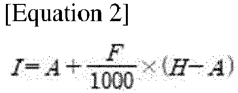
A: Minimum valve current D: Minimum weight voltage F: Height of the work lever H: Maximum load current I: Valve Current - The foregoing is illustrative only and is not intended to be in any way limiting. In addition to the illustrative aspects, embodiments and features described above, in addition aspects, embodiments and features will become apparent by reference to the drawings and the following detailed description.
- A more complete appreciation of the present disclosure will become more apparent by describing in detail embodiments thereof with reference to the accompanying drawings, wherein:
-
FIG. 1 is a graph illustrating a lowering speed of a lever of a conventional forklift equipped with a flow regulator. -
FIG. 2 is a block diagram illustrating a system of controlling a lowering speed of a forklift lever according to an embodiment of the present disclosure. -
FIG. 3 is a graph illustrating a current map, in a controller, which is preset according to a weight of a load. -
FIG. 4 is a graph illustrating a current change map according to a height of a work lever according to an embodiment of the present disclosure. -
FIG. 5 is a graph illustrating a lowering speed of a lever of a forklift according to an embodiment of the present disclosure. - Embodiments will now be described more fully hereinafter with reference to the accompanying drawings. Although the invention may be modified in various manners and have several embodiments, embodiments are illustrated in the accompanying drawings and will be mainly described in the specification. However, the scope of the present invention is not limited to the embodiments and should be construed as including all the changes, equivalents and substitutions included in the spirit and scope of the present invention. These embodiments are provided to more completely explain the present invention to those skilled in the art. It is noted that the figures are schematic and not drawn to scale. The relative dimensions and ratios of the parts in the figures are exaggerated or reduced in size for clarity and convenience and any dimensions are merely exemplary and not limiting. Throughout the description herein, unless otherwise specified, the same or similar reference numeral in different figures refer to the same or similar element formed by a same or similar formation method using a same or similar material(s). In addition, detailed descriptions of well-known functions and configurations that are determined to unnecessarily obscure the subject matter of the present disclosure will be omitted.
- The present disclosure is configured so that a constant amount of change in a lowering speed of a work lever 11, with respect to a valve opening area, is realized, irrespective of a weight of a load placed on the work lever 11, through the use of a
weight sensor 140 without using a separate expensive regulator (e.g., a check valve), thereby increasing the controllability and stability of the forklift operation. -
FIG. 2 is a block diagram illustrating a system of controlling a lowering speed of the forklift lever 11 according to an embodiment of the present disclosure. - In detail, as illustrated in
FIG. 2 , a system of controlling a lowering speed of a work lever 11 of a forklift 10 includes a workmachine operation device 110; acontroller 120 for controlling an RPM of ahydraulic motor 130 and a current amount of anelectronic solenoid valve 150; thehydraulic motor 130 connected to the work lever 11 through a hydraulic line to transmit a power to the work lever 11; aweight sensor 140 provided at one side of the work lever 11 of the forklift 10 to measure a weight of a load placed on the work lever 11; and theelectronic solenoid valve 150 for controlling thehydraulic motor 130 connected to the work lever 11. - In such a case, the
controller 120 may extract only the weight of the load from theweight sensor 140, which simultaneously measures a weight of the work lever 11 and the weight of the load. - In a lowering operation where the load placed on the work lever 11 of the forklift 10 is lowered, the
weight sensor 140 measures the weight of the work lever 11 of the forklift 10, converts the weight into a load voltage G, and transmits the load voltage G to thecontroller 120. - In the
controller 120, a table including a maximum current B under a full load condition and a maximum current C under a no-load condition is preset according to the weight of the load placed on the work lever 11. According to the weight of the load measured by theweight sensor 140, thecontroller 120 determines a maximum current H of theelectronic solenoid valve 150 between the current C under the full load condition and the current B under the no-load condition. -
FIG. 3 is a graph illustrating a current map, in thecontroller 120, which is preset according to the weight of the load. InFIG. 3 , a horizontal axis represents a voltage converted by theweight sensor 140 according to the weight of the load placed on the work lever 11, and a vertical axis represents a preset current corresponding to the horizontal axis. -
FIG. 4 is a graph illustrating a current change map according to a height of the work lever 11 according to an embodiment of the present disclosure. InFIG. 4 , a horizontal axis represents a position of the work lever 11, and a vertical axis represents a current applied to theelectronic solenoid valve 150.FIG. 4 illustrates a map which illustrates a maximum current B under the full load condition and a maximum current C under the no-load condition, according to the position of the work lever 11. Meanwhile,FIG. 3 illustrates the maximum current B under the full load condition and the maximum current C under the no-load condition when the work lever 11 is at a maximum height inFIG. 4 . - For example, as illustrated in
FIG. 3 , when a load of a maximum weight is placed on the work lever 11, a maximum weight voltage E measured and converted by theweight sensor 140 is 4.5 V, and the maximum current (or a valve current) B under the full load condition corresponding thereto in the table is preset to 400 mA. Similarly, when there is no load on the work lever 11, the maximum weight voltage E measured and converted by theweight sensor 140 is 0.25 V, and the maximum current (or a valve current) C under the no-load condition corresponding thereto in the table is preset to 500 mA. - First, when a load is placed on the work lever 11, the
weight sensor 140 transmits, to thecontroller 120, the load voltage (or weight voltage) G according to the weight of the load, and thecontroller 120 determines the maximum load current (or a valve current) H of theelectronic solenoid valve 150, based on the followingEquation 1, by matching the load voltage G in the preset map.
B: Maximum current under full load condition C: Maximum current under no-load condition D: Minimum weight voltage E: Maximum weight voltage G: Load voltage H: Maximum load current - That is, the
controller 120 determines the maximum load current H based on [Equation 1] between the maximum current B under the full load condition and the maximum current C under the no-load condition, and the maximum load current H is illustrated inFIG. 3 . - Thereafter, as illustrated in
FIG. 4 , a map according to a height F of the work lever 11 is preset in thecontroller 120, and a valve current I is obtained by using the maximum load current H determined in thecontroller 120. The valve current I has a current value applied to theelectronic solenoid valve 150, and in detail, thecontroller 120 may obtain the valve current I based on the following [Equation 2].
A: Minimum valve current D: Minimum weight voltage F: Height of the work lever 11 H: Maximum load current I: Valve Current -
FIG. 5 is a graph illustrating a lowering speed of a lever of a forklift according to an embodiment of the present disclosure. - When the system of controlling a lowering speed of the forklift lever according to an embodiment of the present disclosure is used as illustrated in
FIG. 5 , even though a flow regulator as in the conventional art is not provided, a constant amount of change in the lowering speed of the work lever 11, with respect to a valve opening area, may be achieved. That is, even if the flow regulator is not provided, a same change in the lowering speed with respect to a valve opening area may be realized at any point between the full load and the no load. Accordingly, the present disclosure may have a certain controllability, thereby increasing the stability of the forklift. - In addition, since the configuration of the conventional forklift may be used as it is, even though no expensive flow regulator is provided, a relatively low cost weight sensor may be used to measure the weight of the load into a voltage signal and then a signal of the electronic solenoid valve may be controlled based on the voltage signal, so as to realize a uniform change in the lowering speed of the work lever 11 with respect to a valve opening area. Accordingly, a certain operability may be provided during the lowering operation of the work lever 11, and the cost may be reduced such that the economic efficiency may be improved.
- As set forth hereinabove, in a system of controlling a speed of lowering a forklift lever according to one or more embodiments, although the flow regulator is not provided as in the conventional art, a constant amount of change in the speed of lowering the work lever, with respect to a valve opening area, may be achieved.
- That is, although the flow regulator is not provided, a constant amount of change in the lowering speed with respect to a valve opening area may be realized at any point between the full load and the no-load conditions. Accordingly, the present disclosure may have a certain controllability, thereby increasing the stability of the forklift.
- The embodiment of a system of controlling a speed of lowering a forklift lever according to the present disclosure described above is merely exemplary, and it will be apparent to those of ordinary skill in the art that various changes in form and detail may be made thereto without departing from the spirit and scope of the present invention. Therefore, it will be understood that the present invention is not limited to the forms or configurations described in the above detailed description. The true technical protection scope of the present invention will be defined by the technical spirit of the appended claims. It is also to be understood that the present invention includes all modifications, equivalents and substitutions within the spirit and scope of the invention as defined by the appended claims.
Claims (6)
- A system of controlling a lowering speed of a work lever of a forklift, comprising:a hydraulic motor connected to the work lever through a hydraulic line to transmit a power to the work lever;an electronic solenoid valve for controlling the hydraulic motor connected to the work lever;a weight sensor provided at one side of the work lever, the weight sensor measuring a weight of a load placed on the work lever and transmitting the measured value to a controller; anda controller for controlling an RPM of the hydraulic motor and a current amount of the electronic solenoid valve based on the measured value transmitted from the weight sensor,wherein a constant amount of change in a lowering speed of the work lever with respect to a valve opening area is implemented, irrespective of the weight of the load placed on the work lever.
- The system of claim 2, wherein the weight sensor measures the weight of the load placed on the work lever, converts the weight into a load voltage, and transmits the load voltage to the controller.
- The system of claim 2, wherein a table is preset in the controller, the table comprising a maximum current under a full load condition of the load placed on the work lever and a maximum current under a no-load condition, and
the controller determines a maximum load current of the electronic solenoid valve, between the maximum current under the full load condition and the maximum current under the no-load condition, according to the weight of the load measured by the weight sensor. - The system of claim 3, wherein the controller determines the maximum load current of the electronic solenoid valve based on the load voltage and the following Equation 1.

B: Maximum current under full load condition C: Maximum current under no-load condition D: Minimum weight voltage E: Maximum weight voltage G: Load voltage H: Maximum load current - The system of claim 4, wherein a table according to a height of a work lever is preset in the controller, and
the controller determines a valve current applied to the electronic solenoid valve, based on the determined maximum load current. - The system of claim 5, wherein the controller determines the valve current based on the following Equation 2.

A: Minimum valve current D: Minimum weight voltage F: Height of the work lever H: Maximum load current I: Valve Current
Applications Claiming Priority (1)
| Application Number | Priority Date | Filing Date | Title |
|---|---|---|---|
| KR1020180166139A KR102481412B1 (en) | 2018-12-20 | 2018-12-20 | Control system for lowering forklift lever |
Publications (2)
| Publication Number | Publication Date |
|---|---|
| EP3677541A1 true EP3677541A1 (en) | 2020-07-08 |
| EP3677541B1 EP3677541B1 (en) | 2025-10-15 |
Family
ID=69411042
Family Applications (1)
| Application Number | Title | Priority Date | Filing Date |
|---|---|---|---|
| EP19218387.9A Active EP3677541B1 (en) | 2018-12-20 | 2019-12-20 | Control system for lowering forklift lever |
Country Status (4)
| Country | Link |
|---|---|
| US (1) | US11440780B2 (en) |
| EP (1) | EP3677541B1 (en) |
| KR (1) | KR102481412B1 (en) |
| CN (1) | CN111348595B (en) |
Families Citing this family (2)
| Publication number | Priority date | Publication date | Assignee | Title |
|---|---|---|---|---|
| DE102019206658B4 (en) * | 2019-05-09 | 2026-03-05 | Zf Friedrichshafen Ag | Method and device for the transmission control of a working machine |
| CN120646740B (en) * | 2025-08-19 | 2025-10-31 | 凡己科技(苏州)有限公司 | A vehicle and its control method |
Citations (6)
| Publication number | Priority date | Publication date | Assignee | Title |
|---|---|---|---|---|
| US4182126A (en) * | 1978-09-11 | 1980-01-08 | Logisticon, Inc. | Fork lift hydraulic servo control valve |
| JP2000355497A (en) * | 1999-06-16 | 2000-12-26 | Komatsu Forklift Co Ltd | Cylinder control device for cargo handling of forklift truck |
| EP2101065A1 (en) * | 2006-12-07 | 2009-09-16 | Hitachi Construction Machinery Co., Ltd | Torque controller of three pump system for construction machinery |
| JP2009249070A (en) * | 2008-04-02 | 2009-10-29 | Nippon Yusoki Co Ltd | Forklift control system |
| JP2011046499A (en) * | 2009-08-27 | 2011-03-10 | Hitachi Constr Mach Co Ltd | Cargo handling control device of forklift |
| WO2017216935A1 (en) * | 2016-06-16 | 2017-12-21 | ニチユ三菱フォークリフト株式会社 | Industrial vehicle |
Family Cites Families (8)
| Publication number | Priority date | Publication date | Assignee | Title |
|---|---|---|---|---|
| JPH08290900A (en) * | 1995-04-25 | 1996-11-05 | Komatsu Forklift Co Ltd | Cargo handling control device of forklift truck |
| JPH10182095A (en) * | 1996-12-24 | 1998-07-07 | Komatsu Forklift Co Ltd | Forklift truck cargo handling controller |
| JPH11171494A (en) * | 1997-12-11 | 1999-06-29 | Toyota Autom Loom Works Ltd | Cylinder controller of industrial vehicle |
| CN102259809A (en) * | 2010-05-31 | 2011-11-30 | 比亚迪股份有限公司 | Control system and control method of forklift door frame |
| US20140088837A1 (en) * | 2012-09-21 | 2014-03-27 | Erric L. Heitmann | Vehicle With Solicited Carriage Descent |
| EP2857345B1 (en) * | 2013-10-07 | 2017-04-26 | Hyster-Yale Group, Inc. | Reach truck |
| JP6485391B2 (en) * | 2016-03-11 | 2019-03-20 | 株式会社豊田自動織機 | Cargo handling vehicle |
| KR20180028575A (en) * | 2016-09-08 | 2018-03-19 | (주)엠텍 | Operation Safety Motion Base with Sensor at the AGV and Control Method Thereof |
-
2018
- 2018-12-20 KR KR1020180166139A patent/KR102481412B1/en active Active
-
2019
- 2019-12-18 US US16/719,750 patent/US11440780B2/en active Active
- 2019-12-19 CN CN201911318597.3A patent/CN111348595B/en active Active
- 2019-12-20 EP EP19218387.9A patent/EP3677541B1/en active Active
Patent Citations (6)
| Publication number | Priority date | Publication date | Assignee | Title |
|---|---|---|---|---|
| US4182126A (en) * | 1978-09-11 | 1980-01-08 | Logisticon, Inc. | Fork lift hydraulic servo control valve |
| JP2000355497A (en) * | 1999-06-16 | 2000-12-26 | Komatsu Forklift Co Ltd | Cylinder control device for cargo handling of forklift truck |
| EP2101065A1 (en) * | 2006-12-07 | 2009-09-16 | Hitachi Construction Machinery Co., Ltd | Torque controller of three pump system for construction machinery |
| JP2009249070A (en) * | 2008-04-02 | 2009-10-29 | Nippon Yusoki Co Ltd | Forklift control system |
| JP2011046499A (en) * | 2009-08-27 | 2011-03-10 | Hitachi Constr Mach Co Ltd | Cargo handling control device of forklift |
| WO2017216935A1 (en) * | 2016-06-16 | 2017-12-21 | ニチユ三菱フォークリフト株式会社 | Industrial vehicle |
Also Published As
| Publication number | Publication date |
|---|---|
| US11440780B2 (en) | 2022-09-13 |
| KR20200077032A (en) | 2020-06-30 |
| CN111348595A (en) | 2020-06-30 |
| US20200198948A1 (en) | 2020-06-25 |
| CN111348595B (en) | 2021-10-01 |
| KR102481412B1 (en) | 2022-12-26 |
| EP3677541B1 (en) | 2025-10-15 |
Similar Documents
| Publication | Publication Date | Title |
|---|---|---|
| EP2999654B1 (en) | Vacuum tube lifting device and lifting hose and method for control of a vacuum tube lifting device | |
| KR102205660B1 (en) | Articulated robot and gas spring estimation method | |
| EP3677541A1 (en) | Control system for lowering forklift lever | |
| EP2520531A1 (en) | Super-lifting device of crane, control system and control method thereof | |
| US9376297B2 (en) | Reach truck | |
| US7712583B2 (en) | Method and apparatus for controlling automatic lifting and lowering type platform | |
| EP2806085B1 (en) | Vibration suppression method, controller and device for boom thereof | |
| EP2535465A3 (en) | System implementing parallel lift for range of angles | |
| JP2015500191A (en) | Interactive clamping force control system for cargo handling clamps | |
| US11174134B2 (en) | Apparatus for compensating diagonal pull in cranes | |
| EP2281772A3 (en) | A safety device for an aerial lift | |
| CN113173505A (en) | Automatic bottom-opening stacking method and system for gantry crane storage yard, storage medium and gantry crane | |
| US20210061633A1 (en) | Variable Hydraulic Pressure Relief Systems and Methods for a Material Handling Vehicle | |
| US10549973B2 (en) | Industrial truck having a control unit for regulating the movement of a load and method therefor | |
| KR100980668B1 (en) | Integrated automation system for measurement judgment control for lifting large structures using three-dimensional location information | |
| CN110829333A (en) | An anti-vibration hammer for power lines | |
| KR102192118B1 (en) | An Automatic Detection Type of a Load Detecting Apparatus for a Number of Wire in a Crane | |
| CN104495619B (en) | Horizontal falling compensating method of lifting hook for portal crane luffing mechanism of shipyard | |
| KR20130109404A (en) | Automatic fork control device of a fork lift truck and controlling method therefor | |
| CN109048269A (en) | A kind of self-adapting flexible guiding mounting plate | |
| EP3034454B1 (en) | Load measurement method for an industrial truck | |
| CN121872291A (en) | Fork truck portal descending speed stable control system and control method | |
| HK40043977A (en) | Variable hydraulic pressure relief systems and methods for a material handling vehicle | |
| JP6446909B2 (en) | Load measuring device for work equipment | |
| KR20220144897A (en) | Shaft Weight Measuring Method and Apparatus for Variable Shaft Control of Truck |
Legal Events
| Date | Code | Title | Description |
|---|---|---|---|
| PUAI | Public reference made under article 153(3) epc to a published international application that has entered the european phase |
Free format text: ORIGINAL CODE: 0009012 |
|
| STAA | Information on the status of an ep patent application or granted ep patent |
Free format text: STATUS: REQUEST FOR EXAMINATION WAS MADE |
|
| 17P | Request for examination filed |
Effective date: 20191220 |
|
| AK | Designated contracting states |
Kind code of ref document: A1 Designated state(s): AL AT BE BG CH CY CZ DE DK EE ES FI FR GB GR HR HU IE IS IT LI LT LU LV MC MK MT NL NO PL PT RO RS SE SI SK SM TR |
|
| AX | Request for extension of the european patent |
Extension state: BA ME |
|
| RBV | Designated contracting states (corrected) |
Designated state(s): AL AT BE BG CH CY CZ DE DK EE ES FI FR GB GR HR HU IE IS IT LI LT LU LV MC MK MT NL NO PL PT RO RS SE SI SK SM TR |
|
| RAP1 | Party data changed (applicant data changed or rights of an application transferred) |
Owner name: DOOSAN INDUSTRIAL VEHICLE CO., LTD. |
|
| RAP1 | Party data changed (applicant data changed or rights of an application transferred) |
Owner name: DOOSAN INDUSTRIAL VEHICLE CO., LTD. |
|
| STAA | Information on the status of an ep patent application or granted ep patent |
Free format text: STATUS: EXAMINATION IS IN PROGRESS |
|
| 17Q | First examination report despatched |
Effective date: 20221007 |
|
| RAP3 | Party data changed (applicant data changed or rights of an application transferred) |
Owner name: DOOSAN BOBCAT KOREA CO., LTD. |
|
| GRAP | Despatch of communication of intention to grant a patent |
Free format text: ORIGINAL CODE: EPIDOSNIGR1 |
|
| STAA | Information on the status of an ep patent application or granted ep patent |
Free format text: STATUS: GRANT OF PATENT IS INTENDED |
|
| INTG | Intention to grant announced |
Effective date: 20250506 |
|
| GRAS | Grant fee paid |
Free format text: ORIGINAL CODE: EPIDOSNIGR3 |
|
| GRAA | (expected) grant |
Free format text: ORIGINAL CODE: 0009210 |
|
| STAA | Information on the status of an ep patent application or granted ep patent |
Free format text: STATUS: THE PATENT HAS BEEN GRANTED |
|
| AK | Designated contracting states |
Kind code of ref document: B1 Designated state(s): AL AT BE BG CH CY CZ DE DK EE ES FI FR GB GR HR HU IE IS IT LI LT LU LV MC MK MT NL NO PL PT RO RS SE SI SK SM TR |
|
| REG | Reference to a national code |
Ref country code: GB Ref legal event code: FG4D Ref country code: CH Ref legal event code: F10 Free format text: ST27 STATUS EVENT CODE: U-0-0-F10-F00 (AS PROVIDED BY THE NATIONAL OFFICE) Effective date: 20251015 |
|
| REG | Reference to a national code |
Ref country code: IE Ref legal event code: FG4D |
|
| REG | Reference to a national code |
Ref country code: DE Ref legal event code: R096 Ref document number: 602019076833 Country of ref document: DE |
|
| REG | Reference to a national code |
Ref country code: SE Ref legal event code: TRGR |
|
| PGFP | Annual fee paid to national office [announced via postgrant information from national office to epo] |
Ref country code: DE Payment date: 20251203 Year of fee payment: 7 |
|
| PGFP | Annual fee paid to national office [announced via postgrant information from national office to epo] |
Ref country code: GB Payment date: 20251204 Year of fee payment: 7 |
|
| PGFP | Annual fee paid to national office [announced via postgrant information from national office to epo] |
Ref country code: FR Payment date: 20251208 Year of fee payment: 7 |
|
| PGFP | Annual fee paid to national office [announced via postgrant information from national office to epo] |
Ref country code: SE Payment date: 20251210 Year of fee payment: 7 |
|
| REG | Reference to a national code |
Ref country code: NL Ref legal event code: MP Effective date: 20251015 |
|
| REG | Reference to a national code |
Ref country code: AT Ref legal event code: MK05 Ref document number: 1846828 Country of ref document: AT Kind code of ref document: T Effective date: 20251015 |
|
| PG25 | Lapsed in a contracting state [announced via postgrant information from national office to epo] |
Ref country code: NL Free format text: LAPSE BECAUSE OF FAILURE TO SUBMIT A TRANSLATION OF THE DESCRIPTION OR TO PAY THE FEE WITHIN THE PRESCRIBED TIME-LIMIT Effective date: 20251015 |
|
| PG25 | Lapsed in a contracting state [announced via postgrant information from national office to epo] |
Ref country code: ES Free format text: LAPSE BECAUSE OF FAILURE TO SUBMIT A TRANSLATION OF THE DESCRIPTION OR TO PAY THE FEE WITHIN THE PRESCRIBED TIME-LIMIT Effective date: 20251015 |
|
| REG | Reference to a national code |
Ref country code: LT Ref legal event code: MG9D |
|
| PG25 | Lapsed in a contracting state [announced via postgrant information from national office to epo] |
Ref country code: NO Free format text: LAPSE BECAUSE OF FAILURE TO SUBMIT A TRANSLATION OF THE DESCRIPTION OR TO PAY THE FEE WITHIN THE PRESCRIBED TIME-LIMIT Effective date: 20260115 |
|
| PG25 | Lapsed in a contracting state [announced via postgrant information from national office to epo] |
Ref country code: AT Free format text: LAPSE BECAUSE OF FAILURE TO SUBMIT A TRANSLATION OF THE DESCRIPTION OR TO PAY THE FEE WITHIN THE PRESCRIBED TIME-LIMIT Effective date: 20251015 Ref country code: FI Free format text: LAPSE BECAUSE OF FAILURE TO SUBMIT A TRANSLATION OF THE DESCRIPTION OR TO PAY THE FEE WITHIN THE PRESCRIBED TIME-LIMIT Effective date: 20251015 Ref country code: HR Free format text: LAPSE BECAUSE OF FAILURE TO SUBMIT A TRANSLATION OF THE DESCRIPTION OR TO PAY THE FEE WITHIN THE PRESCRIBED TIME-LIMIT Effective date: 20251015 |
|
| PGFP | Annual fee paid to national office [announced via postgrant information from national office to epo] |
Ref country code: IT Payment date: 20251229 Year of fee payment: 7 |
|
| PG25 | Lapsed in a contracting state [announced via postgrant information from national office to epo] |
Ref country code: RS Free format text: LAPSE BECAUSE OF FAILURE TO SUBMIT A TRANSLATION OF THE DESCRIPTION OR TO PAY THE FEE WITHIN THE PRESCRIBED TIME-LIMIT Effective date: 20260115 |
|
| PG25 | Lapsed in a contracting state [announced via postgrant information from national office to epo] |
Ref country code: IS Free format text: LAPSE BECAUSE OF FAILURE TO SUBMIT A TRANSLATION OF THE DESCRIPTION OR TO PAY THE FEE WITHIN THE PRESCRIBED TIME-LIMIT Effective date: 20260215 |
|
| PG25 | Lapsed in a contracting state [announced via postgrant information from national office to epo] |
Ref country code: PT Free format text: LAPSE BECAUSE OF FAILURE TO SUBMIT A TRANSLATION OF THE DESCRIPTION OR TO PAY THE FEE WITHIN THE PRESCRIBED TIME-LIMIT Effective date: 20260216 |
|
| PG25 | Lapsed in a contracting state [announced via postgrant information from national office to epo] |
Ref country code: PL Free format text: LAPSE BECAUSE OF FAILURE TO SUBMIT A TRANSLATION OF THE DESCRIPTION OR TO PAY THE FEE WITHIN THE PRESCRIBED TIME-LIMIT Effective date: 20251015 |
|
| PG25 | Lapsed in a contracting state [announced via postgrant information from national office to epo] |
Ref country code: LV Free format text: LAPSE BECAUSE OF FAILURE TO SUBMIT A TRANSLATION OF THE DESCRIPTION OR TO PAY THE FEE WITHIN THE PRESCRIBED TIME-LIMIT Effective date: 20251015 |