EP3677521A1 - Stretching and deployment of a sensor network for large structure monitoring - Google Patents
Stretching and deployment of a sensor network for large structure monitoring Download PDFInfo
- Publication number
- EP3677521A1 EP3677521A1 EP19212392.5A EP19212392A EP3677521A1 EP 3677521 A1 EP3677521 A1 EP 3677521A1 EP 19212392 A EP19212392 A EP 19212392A EP 3677521 A1 EP3677521 A1 EP 3677521A1
- Authority
- EP
- European Patent Office
- Prior art keywords
- axis
- rod
- rods
- sensor network
- along
- Prior art date
- Legal status (The legal status is an assumption and is not a legal conclusion. Google has not performed a legal analysis and makes no representation as to the accuracy of the status listed.)
- Granted
Links
Images




Classifications
-
- G—PHYSICS
- G01—MEASURING; TESTING
- G01M—TESTING STATIC OR DYNAMIC BALANCE OF MACHINES OR STRUCTURES; TESTING OF STRUCTURES OR APPARATUS, NOT OTHERWISE PROVIDED FOR
- G01M5/00—Investigating the elasticity of structures, e.g. deflection of bridges or air-craft wings
-
- B—PERFORMING OPERATIONS; TRANSPORTING
- B29—WORKING OF PLASTICS; WORKING OF SUBSTANCES IN A PLASTIC STATE IN GENERAL
- B29C—SHAPING OR JOINING OF PLASTICS; SHAPING OF MATERIAL IN A PLASTIC STATE, NOT OTHERWISE PROVIDED FOR; AFTER-TREATMENT OF THE SHAPED PRODUCTS, e.g. REPAIRING
- B29C55/00—Shaping by stretching, e.g. drawing through a die; Apparatus therefor
- B29C55/02—Shaping by stretching, e.g. drawing through a die; Apparatus therefor of plates or sheets
- B29C55/10—Shaping by stretching, e.g. drawing through a die; Apparatus therefor of plates or sheets multiaxial
- B29C55/12—Shaping by stretching, e.g. drawing through a die; Apparatus therefor of plates or sheets multiaxial biaxial
- B29C55/16—Shaping by stretching, e.g. drawing through a die; Apparatus therefor of plates or sheets multiaxial biaxial simultaneously
- B29C55/165—Apparatus therefor
-
- B—PERFORMING OPERATIONS; TRANSPORTING
- B29—WORKING OF PLASTICS; WORKING OF SUBSTANCES IN A PLASTIC STATE IN GENERAL
- B29C—SHAPING OR JOINING OF PLASTICS; SHAPING OF MATERIAL IN A PLASTIC STATE, NOT OTHERWISE PROVIDED FOR; AFTER-TREATMENT OF THE SHAPED PRODUCTS, e.g. REPAIRING
- B29C55/00—Shaping by stretching, e.g. drawing through a die; Apparatus therefor
- B29C55/02—Shaping by stretching, e.g. drawing through a die; Apparatus therefor of plates or sheets
- B29C55/10—Shaping by stretching, e.g. drawing through a die; Apparatus therefor of plates or sheets multiaxial
- B29C55/12—Shaping by stretching, e.g. drawing through a die; Apparatus therefor of plates or sheets multiaxial biaxial
- B29C55/16—Shaping by stretching, e.g. drawing through a die; Apparatus therefor of plates or sheets multiaxial biaxial simultaneously
-
- B—PERFORMING OPERATIONS; TRANSPORTING
- B64—AIRCRAFT; AVIATION; COSMONAUTICS
- B64F—GROUND OR AIRCRAFT-CARRIER-DECK INSTALLATIONS SPECIALLY ADAPTED FOR USE IN CONNECTION WITH AIRCRAFT; DESIGNING, MANUFACTURING, ASSEMBLING, CLEANING, MAINTAINING OR REPAIRING AIRCRAFT, NOT OTHERWISE PROVIDED FOR; HANDLING, TRANSPORTING, TESTING OR INSPECTING AIRCRAFT COMPONENTS, NOT OTHERWISE PROVIDED FOR
- B64F5/00—Designing, manufacturing, assembling, cleaning, maintaining or repairing aircraft, not otherwise provided for; Handling, transporting, testing or inspecting aircraft components, not otherwise provided for
- B64F5/10—Manufacturing or assembling aircraft, e.g. jigs therefor
-
- B—PERFORMING OPERATIONS; TRANSPORTING
- B29—WORKING OF PLASTICS; WORKING OF SUBSTANCES IN A PLASTIC STATE IN GENERAL
- B29L—INDEXING SCHEME ASSOCIATED WITH SUBCLASS B29C, RELATING TO PARTICULAR ARTICLES
- B29L2031/00—Other particular articles
- B29L2031/34—Electrical apparatus, e.g. sparking plugs or parts thereof
Definitions
- the present disclosure relates to a tool that can used to stretch a sensor network film during manufacturing of a sensor network.
- Structure monitoring is a critical safety factor for a wide variety of aerospace and commercial assets, including aircraft components and automotive vehicles. In aerospace platforms, for example, accidents may occur due to structural fatigue and impact damage. Use of newer, lightweight materials including composites introduces new failure mechanisms in aircraft and automotive structures, such as for example delamination, which require additional vigilance with respect to structural integrity. Structural monitoring capabilities are therefore desirable to meet the challenges of future aircraft and other structures.
- Stretchable sensor networks can conformably distribute sensors, actuators and electronics over large structural areas, provide instantaneous information on the structural integrity of the structure and can effectively measure environmental conditions for optimum performance while adding relatively low weight.
- these sensors allow real-time feedback of performance, which has far reaching implications into how future structures (e.g., aerospace structures) are built.
- FIG. 1 A challenge in developing a stretchable sensor network is the optimized placement of sensors and actuators onto a substrate (e.g., film) to ensure that the structural health monitoring system functionalities can be accurately utilized.
- the sensors need to be placed at an optimum distance on the film such that the sensor and actuator signals do not overlap.
- the current practice is generally to manually stretch the film and apply a fabricated sensor layer, which results in a relatively low yield, and as a result a time intensive and relatively expensive manufacturing process. There is a need for a tool to improve the manufacturing process.
- the tool comprises a first rod that extends along a first axis and at a first distal end is secured to a first drive motor that is slidingly secured to a base surface to move perpendicular to the first axis and parallel to a second axis.
- a first idler pulley is connected to a first proximate end of the first rod.
- a first sliding guide moves along the first axis on the first rod, where the first drive motor drives a first drive pulley that is drivingly connected to the first idler pulley to move the first sliding guide along the first axis on the first rod.
- a second rod extends along the second axis and at a second distal end is secured to a second drive motor that is slidingly secured to the base surface to move perpendicular to the second axis and parallel to the first axis.
- a second idler pulley is connected to a second proximate end of the second rod.
- a second sliding guide moves along the second axis on the second rod, where the second drive motor drives a second drive pulley that is drivingly connected to the second idler pulley to move the second idler pulley and the second sliding guide along the second axis on the second rod, where the first idler pulley is secured to and moves with the second slide guide.
- a third rod extends along a third axis and at a third distal end is secured to a third drive motor that is slidingly secured to the base surface to move perpendicular to the third axis and parallel to the second axis.
- a third idler pulley is secured to a proximate end of the third rod.
- a third sliding guide moves along the third axis on the third rod, where the third drive motor drives a third drive pulley that is drivingly connected to the third idler pulley to move the third idler pulley and the third sliding guide along the third axis on the third rod, where the second idler pulley is secured to and moves with the third sliding guide.
- a fourth rod extends along a fourth axis and at a fourth distal end is secured to a fourth drive motor that is slidingly secured to the base surface to move perpendicular to the fourth axis and parallel to the first axis.
- a fourth idler pulley is secured to a proximate end of the fourth rod and that is secured to and moves with the first sliding guide.
- a fourth sliding guide moves along the fourth axis on the fourth rod, where the fourth drive motor drives a fourth drive pulley that is drivingly connected to the fourth idler pulley to move the fourth idler pulley and the fourth sliding guide along the fourth axis on the fourth rod, where the third idler pulley is secured to and moves with the fourth sliding guide.
- the first axis and the third axis are parallel, and the third axis and the fourth axis are parallel.
- a plurality of clips are mounted to each of the first, second, third and fourth rods to hold the sensor network film at its periphery.
- Each of the first, second, third and fourth drive motors may comprise a stepper motor.
- Each of the first, second, third, fourth rods may be positioned in a common plane to stretch the sensor network film in the common plane.
- a first drive belt may be coupled between the first drive motor and the first idler pulley to move the first sliding guide along the first rod.
- a second drive belt may be coupled between the second drive motor and the second idler pulley to move the second sliding guide along the second rod.
- An associated spacing spring located between immediately adjacent ones of the clips on the same of the first, second, third and fourth rods to spread the clips out on its associated on the first, second, third and fourth rods as the sensor film is stretched by moving each of the first, second, third and fourth sliding guides in the direction of its associated one of the first, second, third, fourth distal ends.
- aspects of the disclosure are also directed to a tool for stretching a sensor network film that comprises a first rod that extends along a first axis and moves perpendicular to the first axis and along a second axis.
- a first sliding guide moves along the first axis on the first rod.
- a second rod extends parallel to the second axis and moves perpendicular to the second axis and parallel to the first axis, and a second sliding guide moves along the second axis on the second rod.
- a third rod extends along a third axis and moves perpendicular to the third axis and parallel to the second axis, and a third sliding guide moves along the third axis on the third rod.
- a fourth rod extends along a fourth axis and moves perpendicular to the fourth axis and parallel to the first axis, and a fourth sliding guide moves along the fourth axis on the fourth rod.
- the first axis and the third axis are parallel, and the second axis and the fourth axis are parallel.
- the sensor network film is attached at its periphery to each of the first, second, third and fourth rods, and the first, second, third and fourth rods and the first, second, third and fourth sliding guides move simultaneously to stretch the sensor network film.
- a plurality of clips may be mounted to each of the first, second, third and fourth rods to hold the sensor network film at its periphery, and a plurality of spacing springs may be each uniquely located between adjacent ones of the clips on the same of the first, second, third and fourth rods to spread the clips out on its associated one the first, second, third and fourth rods as the sensor film is stretched by moving each of the first, second, third and fourth sliding guides and the first, second, third and fourth rods to stretch the sensor network film.
- a motor may simultaneously move each of the first, second, third and fourth rods and the first, second, third and fourth sliding guides to stretch the sensor network film.
- a controller may provide command signals to a plurality of motors that simultaneously move each of the first, second, third and fourth rods and the first, second, third and fourth sliding guides to stretch the sensor network film.
- Each of the plurality motors may comprise one of a stepper motor and a torque motor.
- Each of the first, second, third, fourth rods may be positioned in a common plane to stretch the sensor network film in the common plane.
- the motor may comprise at least one of a stepper motor and torque motor.
- Each of the first, second, third and fourth sliding guides may include their own guide movement motor in order to control movement of the first, second, third and fourth sliding guides along its associated rod.
- Each of the first, second, third and fourth rods may include their own rod movement motor in order to control movement of the first, second, third and fourth rods.
- aspects of the disclosure are also directed to stretching a sensor network film, comprising providing a first rod that extends along a first axis and moves perpendicular to the first axis and along a second axis, providing a first sliding guide that moves along the first axis on the first rod, providing a second rod that extends parallel to the second axis and moves perpendicular to the second axis and parallel to the first axis, providing a second sliding guide that moves along the second axis on the second rod, providing a third rod that extends along a third axis and moves perpendicular to the third axis and parallel to the second axis, providing a third sliding guide that moves along the third axis on the third rod, providing a fourth rod that extends along a fourth axis and moves perpendicular to the fourth axis and parallel to the first axis, providing a fourth sliding guide that moves along the fourth axis on the fourth rod.
- the sensor network film is attached at its peripheral edges to each of the first, second, third and fourth rods within a perimeter formed by the first, second, third and fourth sliding guides on the first, second, third and fourth rods.
- the first, second, third and fourth rods and the first, second, third and fourth sliding guides are moved in unison to stretch the sensor network film.
- the sensor network film may be attached by providing a plurality of clips mounted to each of the first, second, third and fourth rods to hold the sensor network film at its periphery, and providing a plurality of spacing springs each uniquely located between adjacent ones of the clips on the same of the first, second, third and fourth rods to spread the clips out on its associated one of the first, second, third and fourth rods as the sensor film is stretched by moving each of the first, second, third and fourth sliding guides and the first, second, third and fourth rods to stretch the sensor network film.
- a motor may be provided that moves each of the first, second, third and fourth rods and the first, second, third and fourth sliding guides to stretch the sensor network film.
- a controller may be provided that issues command signals to a plurality of motors that move each of the first, second, third and fourth rods and the first, second, third and fourth sliding guides in unison to stretch the sensor network film.
- Each of the first, second, third, fourth rods may be positioned in a common plane so the step of moving stretches the sensor network film in the common plane.
- connections are set forth between elements in the following description and in the drawings (the contents of which are incorporated in this specification by way of reference). It is noted that these connections are general and, unless specified otherwise, may be direct or indirect and that this specification is not intended to be limiting in this respect.
- a coupling between two or more entities may refer to a direct connection or an indirect connection.
- An indirect connection may incorporate one or more intervening entities or a space/gap between the entities that are being coupled to one another.
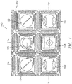
- FIG. 1 is a pictorial illustration of a stretchable sensor network 100, which may include a film 102.
- the film 102 may be, for example, a flexible polyimide material, a polyester film, a fluorpolymer, a copper foil film or an epoxy glass film.
- the film 102 is stretched and components (e.g., sensors, integrated circuits, et cetera) are placed at various node locations 104-109 of the film 102. See U.S. Patent Application No. 2018/0317322 which is assigned to the assignee of the present invention and incorporated herein by reference.
- the film may be placed into a stretching tool.
- FIG. 2 is a simplified pictorial illustration of a stretching tool 200 mounted on a base surface 202 and in a closed position.
- the tool 200 includes a first rod 204 that extends along a first axis and at a first distal end 206 is secured to a first drive motor 208.
- the first drive motor 208 is slidingly secured to the base surface 202 to move perpendicular to the first axis and parallel to a second axis.
- the first rod 204 also includes a first proximate end 210 that is secured to a first idler pulley 212.
- a first sliding guide 214 moves along the first axis on the first rod 204 under the control of a first belt (not shown in FIG.
- the first drive motor 208 drives a first drive pulley 216 that is drivingly connected to the first idler pulley 212 via the first belt (not shown in FIG. 2 ) to move the first sliding guide 214 along the first axis on the first rod 204.
- the tool 200 also includes a second rod 218 that extends along the second axis and at a second distal end 220 is secured to a second drive motor 222.
- the second drive motor 222 is slidingly secured to the base surface 202 to move perpendicular to the second axis and parallel to the first axis.
- the second rod also includes a second proximate end 224 is secured to a second idler pulley 226.
- the second idler pulley 226 is secured to and moves with a third sliding guide 238.
- the second sliding guide 228 moves along the second axis on the second rod 218 under the control of a second belt (not shown in FIG2 ) that extends between a second drive pulley 230 of the second drive motor 222 and the second idler pulley 230.
- the second drive motor 222 drives the second drive pulley 230 that is drivingly connected to the second idler pulley 226 (e.g., via the second belt not shown in FIG. 2 ) to move the second sliding guide 228 along the second axis on the second rod 218.
- the tool 200 further comprises a third rod 230 that extends along a third axis and at a third distal end 232 is secured to a third drive motor 234.
- the third drive motor 234 is slidingly secured to the base surface 202 to move perpendicular to the third axis and parallel to the second axis.
- the third rod 230 includes a third proximate end 234 that is secured to a third idler pulley 236.
- the third idler pulley 236 is secured to and moves with a fourth sliding guide 252.
- the third sliding guide 238 moves along the third axis on the third rod 230 under the control of a third belt, where the third drive motor 234 drives a third drive pulley 240 that is drivingly connected to the third idler pulley 236 to move the third sliding guide 238 along the third axis on the third rod 230.
- a fourth rod 242 extends along a fourth axis and at a fourth distal end 244 is secured to a fourth drive motor 246.
- the fourth drive motor is slidingly secured to the base surface 202 to move perpendicular to the fourth axis and parallel to the first axis.
- the fourth rod 242 includes a fourth proximate end 248 is secured to a fourth idler pulley 250.
- the fourth idler pulley 250 is secured to and moves with the first sliding guide 214.
- the fourth sliding guide 252 moves along the fourth axis on the fourth rod 242 under the control of a fourth belt (not shown in FIG. 2 ) that extends between the fourth drive motor 244 and the fourth idler pulley 250.
- the fourth drive motor 250 drives the fourth drive pulley 254 that is drivingly connected to the fourth idler pulley 250 to move the fourth sliding guide 252 along the fourth axis on the fourth rod 242.
- the tool 200 also includes a controller 260 (e.g., a processor) that sends command signals to the first, second, third and fourth motors 208, 222, 234 and 246 to move the guides 214, 228, 238 and 252 along their respective rods 204, 218, 230 and 242.
- the movement of the guides and the motors may be simultaneous to balance the tension on the film as it is stretched.
- first rod/axis 204 and the third rod/axis 230 are parallel, and the second rod/axis 218 and the fourth rod/axis 242 are parallel.
- each of the first, second, third, fourth rods is positioned in a common plane to stretch the sensor network film in the common plane.
- FIG. 3 is a simplified pictorial illustration of the stretching tool 200 mounted on the base surface 202 and in an intermediate position with a plurality of clips 300-311 spaced along the first, second, third and fourth rods 202, 218, 230 and 242.
- Each of the plurality of clips 300-311 are mounted to a respective one of the first, second, third and fourth rods to hold the sensor network film at its periphery and an associated spacing spring (not shown in FIG. 3 ) is located between adjacent ones of the clips 300-311 on the same of the first, second, third and fourth rods. The springs spread the clips out on its associated one of the first, second, third and fourth rods as the sensor film is stretched.
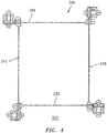
- FIG. 4 is a simplified pictorial illustration of the stretching tool 200 in a fully open position with the clips removed for ease of illustration.
- FIG. 5 is an isometric view of a portion of the tool of FIGs. 2-4 with a film 500 secured to the tool 200 by the plurality of clips (e.g., 300-311) for stretching of the film under the control of the controller 260 ( FIG. 2 ). It is contemplated that the film may be secured to the tool in various ways, including for example, clips, clamps, et cetera
- FIG. 6 is a top view of the tool 200 of FIGs. 2-5 with the film 500 secured to the tool 200 by the clips 300-311.
- a first drive belt 502 is coupled between the first drive motor 208 and the first idler pulley 214 to move the first sliding guide 214 along the first rod 204.
- a second drive belt 504 is coupled between the second drive motor 222 and the second idler pulley 226 to move second sliding guide 228 along the second rod 218.
- the third and fourth rods also include similar belts interconnecting the associated motor and idler pulley for the particular rod.
- each of the belts may be connected to its associated guide via a clamp.
- Each of the guides may include a recess through which its associate rod may pass and ride upon.
- the fourth rod 242 may pass through a recess 520 and a fourth belt 522 is secured to the fourth sliding guide 252 via a clamp 524. As the fourth motor moves the fourth belt 522 the fourth sliding guide 252 moves along the fourth rod 242.
- FIG. 7 is an isometric view of the tool 200 with the film 500 secured to the tool by the clips for stretching, but showing one clip 300 on the fourth rod 242 and a spacing spring 700 (e.g., tapered) that separates an immediately adjacent clip (not shown).
- An associated spacing spring is located between adjacent ones of the clips on the same of the first, second, third and fourth rods in order to spread the clips out on its associated on the first, second, third and fourth rods as the sensor film is stretched by moving each of the first, second, third and fourth sliding guides in the direction of its associated one of the first, second, third, fourth distal end, and at least three of the drive motors.
- FIG. 3 illustrates the clips equally spaced on their respective rods as a result of forces applied by the spacing springs.
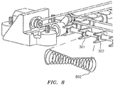
- FIG. 8 is an isometric view of a portion of the tool with an hour glass spacing spring 802 located between adjacent clips 301, 302.
- An hour glass spacing spring is located between adjacent ones of the clips on the first, second, third and fourth rods in order to spread the clips out on its associated one of the first, second, third and fourth rods as the film is stretched by moving each of the first, second, third and fourth sliding guides in the direction of its associated one of the first, second, third, fourth distal end and moving the motors to balance tension on the film as it is stretched.
- the spring may have various shapes in order to keep the clips evenly spaced during opening and closing of the tool.
- each of the sliding guides may include their own motor in order to control movement of the sliding guide along its associated rod.
- This embodiment may include first, second, third and fourth drive motors to move the rods and a motor (e.g., stepper or torque) in each of the sliding guides to simultaneously move the sliding guides.
- a single drove motors may be used to move each of the rods, and one or more motors may be used to move the sliding guides along their associated rod.
- the film e.g., rectangular
- the controller commands the first, second, third and fourth motors (e.g., stepper motors) to simultaneously move the first, second, third and fourth sliding guides in the distal direction (i.e., outwardly), which also causes the motors themselves to move.
- the amount of movement is controlled by the stepper motors and movements are simultaneous in order to balance forces on the film.
- the clips may be additively manufactured. One or more servo motors may be used than stepper motors.
- the control of the motors via the controller and arrangement of the tool may be based upon the shape of the film (e.g., square, rectangular, round, oval, et cetera). Once the film is stretched the desired amount various electronic components may then be secured to the film to provide the desired sensor network.
- a single drive motor may be used rather than one for each rod in order to move the slides in order to stretch the film.
- all but one of the motors may be replaced by slides that move similar to the motors to balance tension on the film as it is stretched.
- any carrier may be used such as a rail, triangular cross section structure, et cetera.
- belts are used in the embodiments presented in herein to couple the motors to the glides, it is contemplated that any connection mechanism may be used to transmit the motive force to the sliding guide in order to stretch the film in a controller matter.
- the film may be attached to the tool a number of different ways.
Landscapes
- Engineering & Computer Science (AREA)
- Manufacturing & Machinery (AREA)
- Mechanical Engineering (AREA)
- Aviation & Aerospace Engineering (AREA)
- Transportation (AREA)
- Physics & Mathematics (AREA)
- General Physics & Mathematics (AREA)
- Shaping By String And By Release Of Stress In Plastics And The Like (AREA)
Abstract
Description
- The present disclosure relates to a tool that can used to stretch a sensor network film during manufacturing of a sensor network.
- Structure monitoring is a critical safety factor for a wide variety of aerospace and commercial assets, including aircraft components and automotive vehicles. In aerospace platforms, for example, accidents may occur due to structural fatigue and impact damage. Use of newer, lightweight materials including composites introduces new failure mechanisms in aircraft and automotive structures, such as for example delamination, which require additional vigilance with respect to structural integrity. Structural monitoring capabilities are therefore desirable to meet the challenges of future aircraft and other structures.
- Stretchable sensor networks can conformably distribute sensors, actuators and electronics over large structural areas, provide instantaneous information on the structural integrity of the structure and can effectively measure environmental conditions for optimum performance while adding relatively low weight. In addition, these sensors allow real-time feedback of performance, which has far reaching implications into how future structures (e.g., aerospace structures) are built.
- Sensor networks to sense pressure, temperature, strain or impact have been demonstrated as shown in
FIG. 1 . A challenge in developing a stretchable sensor network is the optimized placement of sensors and actuators onto a substrate (e.g., film) to ensure that the structural health monitoring system functionalities can be accurately utilized. The sensors need to be placed at an optimum distance on the film such that the sensor and actuator signals do not overlap. The current practice is generally to manually stretch the film and apply a fabricated sensor layer, which results in a relatively low yield, and as a result a time intensive and relatively expensive manufacturing process. There is a need for a tool to improve the manufacturing process. - The following presents a simplified summary in order to provide a basic understanding of some aspects of the disclosure. The summary is not an extensive overview of the disclosure. It is neither intended to identify key or critical elements of the disclosure nor to delineate the scope of the disclosure. The following summary merely presents some concepts of the disclosure in a simplified form as a prelude to the description below.
- Aspects of the disclosure are directed to a tool for stretching a sensor network film. The tool comprises a first rod that extends along a first axis and at a first distal end is secured to a first drive motor that is slidingly secured to a base surface to move perpendicular to the first axis and parallel to a second axis. A first idler pulley is connected to a first proximate end of the first rod. A first sliding guide moves along the first axis on the first rod, where the first drive motor drives a first drive pulley that is drivingly connected to the first idler pulley to move the first sliding guide along the first axis on the first rod. A second rod extends along the second axis and at a second distal end is secured to a second drive motor that is slidingly secured to the base surface to move perpendicular to the second axis and parallel to the first axis. A second idler pulley is connected to a second proximate end of the second rod. A second sliding guide moves along the second axis on the second rod, where the second drive motor drives a second drive pulley that is drivingly connected to the second idler pulley to move the second idler pulley and the second sliding guide along the second axis on the second rod, where the first idler pulley is secured to and moves with the second slide guide. A third rod extends along a third axis and at a third distal end is secured to a third drive motor that is slidingly secured to the base surface to move perpendicular to the third axis and parallel to the second axis. A third idler pulley is secured to a proximate end of the third rod. A third sliding guide moves along the third axis on the third rod, where the third drive motor drives a third drive pulley that is drivingly connected to the third idler pulley to move the third idler pulley and the third sliding guide along the third axis on the third rod, where the second idler pulley is secured to and moves with the third sliding guide. A fourth rod extends along a fourth axis and at a fourth distal end is secured to a fourth drive motor that is slidingly secured to the base surface to move perpendicular to the fourth axis and parallel to the first axis. A fourth idler pulley is secured to a proximate end of the fourth rod and that is secured to and moves with the first sliding guide. A fourth sliding guide moves along the fourth axis on the fourth rod, where the fourth drive motor drives a fourth drive pulley that is drivingly connected to the fourth idler pulley to move the fourth idler pulley and the fourth sliding guide along the fourth axis on the fourth rod, where the third idler pulley is secured to and moves with the fourth sliding guide. The first axis and the third axis are parallel, and the third axis and the fourth axis are parallel. A plurality of clips are mounted to each of the first, second, third and fourth rods to hold the sensor network film at its periphery.
- Each of the first, second, third and fourth drive motors may comprise a stepper motor.
- Each of the first, second, third, fourth rods may be positioned in a common plane to stretch the sensor network film in the common plane.
- A first drive belt may be coupled between the first drive motor and the first idler pulley to move the first sliding guide along the first rod.
- A second drive belt may be coupled between the second drive motor and the second idler pulley to move the second sliding guide along the second rod.
- An associated spacing spring located between immediately adjacent ones of the clips on the same of the first, second, third and fourth rods to spread the clips out on its associated on the first, second, third and fourth rods as the sensor film is stretched by moving each of the first, second, third and fourth sliding guides in the direction of its associated one of the first, second, third, fourth distal ends.
- Aspects of the disclosure are also directed to a tool for stretching a sensor network film that comprises a first rod that extends along a first axis and moves perpendicular to the first axis and along a second axis. A first sliding guide moves along the first axis on the first rod. A second rod extends parallel to the second axis and moves perpendicular to the second axis and parallel to the first axis, and a second sliding guide moves along the second axis on the second rod. A third rod extends along a third axis and moves perpendicular to the third axis and parallel to the second axis, and a third sliding guide moves along the third axis on the third rod. A fourth rod extends along a fourth axis and moves perpendicular to the fourth axis and parallel to the first axis, and a fourth sliding guide moves along the fourth axis on the fourth rod. The first axis and the third axis are parallel, and the second axis and the fourth axis are parallel. The sensor network film is attached at its periphery to each of the first, second, third and fourth rods, and the first, second, third and fourth rods and the first, second, third and fourth sliding guides move simultaneously to stretch the sensor network film.
- A plurality of clips may be mounted to each of the first, second, third and fourth rods to hold the sensor network film at its periphery, and a plurality of spacing springs may be each uniquely located between adjacent ones of the clips on the same of the first, second, third and fourth rods to spread the clips out on its associated one the first, second, third and fourth rods as the sensor film is stretched by moving each of the first, second, third and fourth sliding guides and the first, second, third and fourth rods to stretch the sensor network film.
- A motor may simultaneously move each of the first, second, third and fourth rods and the first, second, third and fourth sliding guides to stretch the sensor network film.
- A controller may provide command signals to a plurality of motors that simultaneously move each of the first, second, third and fourth rods and the first, second, third and fourth sliding guides to stretch the sensor network film.
- Each of the plurality motors may comprise one of a stepper motor and a torque motor.
- Each of the first, second, third, fourth rods may be positioned in a common plane to stretch the sensor network film in the common plane.
- The motor may comprise at least one of a stepper motor and torque motor.
- Each of the first, second, third and fourth sliding guides may include their own guide movement motor in order to control movement of the first, second, third and fourth sliding guides along its associated rod.
- Each of the first, second, third and fourth rods may include their own rod movement motor in order to control movement of the first, second, third and fourth rods.
- Aspects of the disclosure are also directed to stretching a sensor network film, comprising providing a first rod that extends along a first axis and moves perpendicular to the first axis and along a second axis, providing a first sliding guide that moves along the first axis on the first rod, providing a second rod that extends parallel to the second axis and moves perpendicular to the second axis and parallel to the first axis, providing a second sliding guide that moves along the second axis on the second rod, providing a third rod that extends along a third axis and moves perpendicular to the third axis and parallel to the second axis, providing a third sliding guide that moves along the third axis on the third rod, providing a fourth rod that extends along a fourth axis and moves perpendicular to the fourth axis and parallel to the first axis, providing a fourth sliding guide that moves along the fourth axis on the fourth rod. The sensor network film is attached at its peripheral edges to each of the first, second, third and fourth rods within a perimeter formed by the first, second, third and fourth sliding guides on the first, second, third and fourth rods. The first, second, third and fourth rods and the first, second, third and fourth sliding guides are moved in unison to stretch the sensor network film.
- The sensor network film may be attached by providing a plurality of clips mounted to each of the first, second, third and fourth rods to hold the sensor network film at its periphery, and providing a plurality of spacing springs each uniquely located between adjacent ones of the clips on the same of the first, second, third and fourth rods to spread the clips out on its associated one of the first, second, third and fourth rods as the sensor film is stretched by moving each of the first, second, third and fourth sliding guides and the first, second, third and fourth rods to stretch the sensor network film.
- A motor may be provided that moves each of the first, second, third and fourth rods and the first, second, third and fourth sliding guides to stretch the sensor network film.
- A controller may be provided that issues command signals to a plurality of motors that move each of the first, second, third and fourth rods and the first, second, third and fourth sliding guides in unison to stretch the sensor network film.
- Each of the first, second, third, fourth rods may be positioned in a common plane so the step of moving stretches the sensor network film in the common plane.
- Various features will become apparent to those skilled in the art from the following detailed description of the disclosed non-limiting embodiments. The drawings that accompany the detailed description can be briefly described as follows:
-
FIG. 1 is a pictorial illustration of a stretchable sensor network; -
FIG. 2 is a simplified pictorial illustration of a stretching tool mounted on a base surface in a closed position; -
FIG. 3 is a simplified pictorial illustration of the stretching tool mounted on the base surface and in an intermediate position with clips spaced along first, second, third and fourth rods; -
FIG. 4 is a simplified pictorial illustration of the stretching tool in a fully open position with the clips removed; -
FIG. 5 is an isometric view of the tool with a film secured to the tool by the clips for stretching; -
FIG. 6 is a top view of the tool with the film secured to the tool by the clips for stretching; -
FIG. 7 is an isometric view of the tool with the film secured to the tool by the clips for stretching and showing one clip on the fourth rod with a tapered spring that separates an adjacent clip; and -
FIG. 8 is an isometric view of a portion of the tool with an hour glass shaped spacing spring located between adjacent clips. - It is noted that various connections are set forth between elements in the following description and in the drawings (the contents of which are incorporated in this specification by way of reference). It is noted that these connections are general and, unless specified otherwise, may be direct or indirect and that this specification is not intended to be limiting in this respect. A coupling between two or more entities may refer to a direct connection or an indirect connection. An indirect connection may incorporate one or more intervening entities or a space/gap between the entities that are being coupled to one another.
-
FIG. 1 is a pictorial illustration of astretchable sensor network 100, which may include afilm 102. Thefilm 102 may be, for example, a flexible polyimide material, a polyester film, a fluorpolymer, a copper foil film or an epoxy glass film. To manufacture a sensor network, thefilm 102 is stretched and components (e.g., sensors, integrated circuits, et cetera) are placed at various node locations 104-109 of thefilm 102. SeeU.S. Patent Application No. 2018/0317322 which is assigned to the assignee of the present invention and incorporated herein by reference. To stretch thefilm 102 the film may be placed into a stretching tool. -
FIG. 2 is a simplified pictorial illustration of astretching tool 200 mounted on abase surface 202 and in a closed position. Thetool 200 includes afirst rod 204 that extends along a first axis and at a firstdistal end 206 is secured to afirst drive motor 208. Thefirst drive motor 208 is slidingly secured to thebase surface 202 to move perpendicular to the first axis and parallel to a second axis. Thefirst rod 204 also includes a firstproximate end 210 that is secured to a firstidler pulley 212. A first slidingguide 214 moves along the first axis on thefirst rod 204 under the control of a first belt (not shown inFIG. 2 ) that extends between thefirst drive motor 208 and the firstidler pulley 212. The firstidler pulley 212 is secured to and moves with a second slidingguide 228. Thefirst drive motor 208 drives afirst drive pulley 216 that is drivingly connected to the firstidler pulley 212 via the first belt (not shown inFIG. 2 ) to move the first slidingguide 214 along the first axis on thefirst rod 204. - The
tool 200 also includes asecond rod 218 that extends along the second axis and at a seconddistal end 220 is secured to asecond drive motor 222. Thesecond drive motor 222 is slidingly secured to thebase surface 202 to move perpendicular to the second axis and parallel to the first axis. The second rod also includes a secondproximate end 224 is secured to a secondidler pulley 226. The secondidler pulley 226 is secured to and moves with a third slidingguide 238. The second slidingguide 228 moves along the second axis on thesecond rod 218 under the control of a second belt (not shown inFIG2 ) that extends between asecond drive pulley 230 of thesecond drive motor 222 and the secondidler pulley 230. Thesecond drive motor 222 drives thesecond drive pulley 230 that is drivingly connected to the second idler pulley 226 (e.g., via the second belt not shown inFIG. 2 ) to move the second slidingguide 228 along the second axis on thesecond rod 218. - The
tool 200 further comprises athird rod 230 that extends along a third axis and at a thirddistal end 232 is secured to athird drive motor 234. Thethird drive motor 234 is slidingly secured to thebase surface 202 to move perpendicular to the third axis and parallel to the second axis. Thethird rod 230 includes a thirdproximate end 234 that is secured to a thirdidler pulley 236. The thirdidler pulley 236 is secured to and moves with a fourth slidingguide 252. The third slidingguide 238 moves along the third axis on thethird rod 230 under the control of a third belt, where thethird drive motor 234 drives athird drive pulley 240 that is drivingly connected to the thirdidler pulley 236 to move the third slidingguide 238 along the third axis on thethird rod 230. - A
fourth rod 242 extends along a fourth axis and at a fourthdistal end 244 is secured to afourth drive motor 246. The fourth drive motor is slidingly secured to thebase surface 202 to move perpendicular to the fourth axis and parallel to the first axis. Thefourth rod 242 includes a fourthproximate end 248 is secured to a fourthidler pulley 250. The fourthidler pulley 250 is secured to and moves with the first slidingguide 214. The fourth slidingguide 252 moves along the fourth axis on thefourth rod 242 under the control of a fourth belt (not shown inFIG. 2 ) that extends between thefourth drive motor 244 and the fourthidler pulley 250. Thefourth drive motor 250 drives thefourth drive pulley 254 that is drivingly connected to the fourthidler pulley 250 to move the fourth slidingguide 252 along the fourth axis on thefourth rod 242. - The
tool 200 also includes a controller 260 (e.g., a processor) that sends command signals to the first, second, third andfourth motors guides respective rods - In one embodiment, the first rod/
axis 204 and the third rod/axis 230 are parallel, and the second rod/axis 218 and the fourth rod/axis 242 are parallel. In addition, each of the first, second, third, fourth rods is positioned in a common plane to stretch the sensor network film in the common plane. -
FIG. 3 is a simplified pictorial illustration of the stretchingtool 200 mounted on thebase surface 202 and in an intermediate position with a plurality of clips 300-311 spaced along the first, second, third andfourth rods FIG. 3 ) is located between adjacent ones of the clips 300-311 on the same of the first, second, third and fourth rods. The springs spread the clips out on its associated one of the first, second, third and fourth rods as the sensor film is stretched. -
FIG. 4 is a simplified pictorial illustration of the stretchingtool 200 in a fully open position with the clips removed for ease of illustration. -
FIG. 5 is an isometric view of a portion of the tool ofFIGs. 2-4 with afilm 500 secured to thetool 200 by the plurality of clips (e.g., 300-311) for stretching of the film under the control of the controller 260 (FIG. 2 ). It is contemplated that the film may be secured to the tool in various ways, including for example, clips, clamps, et ceteraFIG. 6 is a top view of thetool 200 ofFIGs. 2-5 with thefilm 500 secured to thetool 200 by the clips 300-311. Afirst drive belt 502 is coupled between thefirst drive motor 208 and the firstidler pulley 214 to move the first slidingguide 214 along thefirst rod 204. Similarly, asecond drive belt 504 is coupled between thesecond drive motor 222 and the secondidler pulley 226 to move second slidingguide 228 along thesecond rod 218. The third and fourth rods also include similar belts interconnecting the associated motor and idler pulley for the particular rod. - Referring still to
FIG. 5 , each of the belts may be connected to its associated guide via a clamp. Each of the guides may include a recess through which its associate rod may pass and ride upon. For example, thefourth rod 242 may pass through arecess 520 and afourth belt 522 is secured to the fourth slidingguide 252 via aclamp 524. As the fourth motor moves thefourth belt 522 the fourth slidingguide 252 moves along thefourth rod 242. -
FIG. 7 is an isometric view of thetool 200 with thefilm 500 secured to the tool by the clips for stretching, but showing oneclip 300 on thefourth rod 242 and a spacing spring 700 (e.g., tapered) that separates an immediately adjacent clip (not shown). An associated spacing spring is located between adjacent ones of the clips on the same of the first, second, third and fourth rods in order to spread the clips out on its associated on the first, second, third and fourth rods as the sensor film is stretched by moving each of the first, second, third and fourth sliding guides in the direction of its associated one of the first, second, third, fourth distal end, and at least three of the drive motors.FIG. 3 illustrates the clips equally spaced on their respective rods as a result of forces applied by the spacing springs. -
FIG. 8 is an isometric view of a portion of the tool with an hourglass spacing spring 802 located betweenadjacent clips - It is contemplated that rather than belts or other linkage to move the sliding guides, that each of the sliding guides may include their own motor in order to control movement of the sliding guide along its associated rod. This embodiment may include first, second, third and fourth drive motors to move the rods and a motor (e.g., stepper or torque) in each of the sliding guides to simultaneously move the sliding guides. Similarly, rather than four drive motors, a single drove motors may be used to move each of the rods, and one or more motors may be used to move the sliding guides along their associated rod.
- In one embodiment, to stretch a film, the film (e.g., rectangular) is secured to the clips at the periphery of the film while the tool is in the closed position as illustrated in
FIG. 3 . Once secured, the controller then commands the first, second, third and fourth motors (e.g., stepper motors) to simultaneously move the first, second, third and fourth sliding guides in the distal direction (i.e., outwardly), which also causes the motors themselves to move. The amount of movement is controlled by the stepper motors and movements are simultaneous in order to balance forces on the film. The clips may be additively manufactured. One or more servo motors may be used than stepper motors. The control of the motors via the controller and arrangement of the tool (e.g., the rods) may be based upon the shape of the film (e.g., square, rectangular, round, oval, et cetera). Once the film is stretched the desired amount various electronic components may then be secured to the film to provide the desired sensor network. - It is contemplated that a single drive motor may be used rather than one for each rod in order to move the slides in order to stretch the film. In this case all but one of the motors may be replaced by slides that move similar to the motors to balance tension on the film as it is stretched. In addition, although the tool is discussed as using rods for the sliding glides to move along, it is contemplated that any carrier may be used such as a rail, triangular cross section structure, et cetera. Similar, although belts are used in the embodiments presented in herein to couple the motors to the glides, it is contemplated that any connection mechanism may be used to transmit the motive force to the sliding guide in order to stretch the film in a controller matter. A skilled person will also appreciate that the film may be attached to the tool a number of different ways.
- It should be understood that relative positional terms such as "forward," "aft," "upper," "lower," "above," "below," and the like are with reference to the normal operational attitude of the vehicle and should not be considered otherwise limiting.
- Although the different non-limiting embodiments have specific illustrated components, the embodiments of this invention are not limited to those particular combinations. It is possible to use some of the components or features from any of the non-limiting embodiments in combination with features or components from any of the other non-limiting embodiments.
- It should be understood that like reference numerals identify corresponding or similar elements throughout the several drawings. It should also be understood that although a particular component arrangement is disclosed in the illustrated embodiment, other arrangements will benefit herefrom.
- The foregoing description is exemplary rather than defined by the features within. Various non-limiting embodiments are disclosed herein, however, one of ordinary skill in the art would recognize that various modifications and variations in light of the above teachings will fall within the scope of the appended claims. It is therefore to be understood that within the scope of the appended claims, the disclosure may be practiced other than as specifically described. For that reason the appended claims should be studied to determine true scope and content.
Claims (15)
- A tool for stretching a sensor network film, comprising:a first rod that extends along a first axis and at a first distal end is secured to a first drive motor that is slidingly secured to a base surface to move perpendicular to the first axis and parallel to a second axis;a first idler pulley that is connected to a first proximate end of the first rod;a first sliding guide that moves along the first axis on the first rod, where the first drive motor drives a first drive pulley that is drivingly connected to the first idler pulley to move the first sliding guide along the first axis on the first rod;a second rod that extends along the second axis and at a second distal end is secured to a second drive motor that is slidingly secured to the base surface to move perpendicular to the second axis and parallel to the first axis;a second idler pulley that is connected to a second proximate end of the second rod;a second sliding guide that moves along the second axis on the second rod, where the second drive motor drives a second drive pulley that is drivingly connected to the second idler pulley to move the second idler pulley and the second sliding guide along the second axis on the second rod, where the first idler pulley is secured to and moves with the second slide guide;a third rod that extends along a third axis and at a third distal end is secured to a third drive motor that is slidingly secured to the base surface to move perpendicular to the third axis and parallel to the second axis;a third idler pulley that is secured to a proximate end of the third rod;a third sliding guide that moves along the third axis on the third rod, where the third drive motor drives a third drive pulley that is drivingly connected to the third idler pulley to move the third idler pulley and the third sliding guide along the third axis on the third rod, where the second idler pulley is secured to and moves with the third sliding guide;a fourth rod that extends along a fourth axis and at a fourth distal end is secured to a fourth drive motor that is slidingly secured to the base surface to move perpendicular to the fourth axis and parallel to the first axis;a fourth idler pulley that is secured to a proximate end of the fourth rod and that is secured to and moves with the first sliding guide; anda fourth sliding guide that moves along the fourth axis on the fourth rod, where the fourth drive motor drives a fourth drive pulley that is drivingly connected to the fourth idler pulley to move the fourth idler pulley and the fourth sliding guide along the fourth axis on the fourth rod, where the third idler pulley is secured to and moves with the fourth sliding guide;where the first axis and the third axis are parallel, and the second axis and the fourth axis are parallel;where a plurality of clips are mounted to each of the first, second, third and fourth rods to hold the sensor network film at its periphery.
- The tool of claim 1, where each of the first, second, third and fourth drive motors comprises a stepper motor.
- The tool of claim 1 or 2, where each of the first, second, third, fourth rods is positioned in a common plane to stretch the sensor network film in the common plane.
- The tool of claim 1, 2 or 3, where a first drive belt is coupled between the first drive motor and the first idler pulley to move the first sliding guide along the first rod.
- The tool of claim 4, where a second drive belt is coupled between the second drive motor and the second idler pulley to move the second sliding guide along the second rod.
- The tool of any preceding claim, further comprising an associated spacing spring located between immediately adjacent ones of the clips on the same of the first, second, third and fourth rods to spread the clips out on its associated on the first, second, third and fourth rods as the sensor film is stretched by moving each of the first, second, third and fourth sliding guides in the direction of its associated one of the first, second, third, fourth distal ends.
- A tool for stretching a sensor network film, comprising:a first rod that extends along a first axis and moves perpendicular to the first axis and along a second axis;a first sliding guide that moves along the first axis on the first rod;a second rod that extends parallel to the second axis and moves perpendicular to the second axis and parallel to the first axis;a second sliding guide that moves along the second axis on the second rod;a third rod that extends along a third axis and moves perpendicular to the third axis and parallel to the second axis;a third sliding guide that moves along the third axis on the third rod;a fourth rod that extends along a fourth axis and moves perpendicular to the fourth axis and parallel to the first axis; anda fourth sliding guide that moves along the fourth axis on the fourth rod;where the first axis and the third axis are parallel, and the second axis and the fourth axis are parallel;where the sensor network film is attached at its periphery to each of the first, second, third and fourth rods, and the first, second, third and fourth rods and the first, second, third and fourth sliding guides move simultaneously to stretch the sensor network film,wherein the tool optionally further comprises:
a plurality of clips mounted to each of the first, second, third and fourth rods to hold the sensor network film at its periphery, and a plurality of spacing springs each uniquely located between adjacent ones of the clips on the same of the first, second, third and fourth rods to spread the clips out on its associated one of the first, second, third and fourth rods as the sensor film is stretched by moving each of the first, second, third and fourth sliding guides and the first, second, third and fourth rods to stretch the sensor network film. - The tool of claim 7, further comprising a motor that simultaneously moves each of the first, second, third and fourth rods and the first, second, third and fourth sliding guides to stretch the sensor network film, where the motor optionally comprises at least one of a stepper motor and torque motor.
- The tool of claim 7, further comprising a controller that provides command signals to a plurality of motors that simultaneously move each of the first, second, third and fourth rods and the first, second, third and fourth sliding guides to stretch the sensor network film, where each of the plurality motors optionally comprises one of a stepper motor and a torque motor.
- The tool of claim 7, 8 or 9, where each of the first, second, third, fourth rods is positioned in a common plane to stretch the sensor network film in the common plane.
- The tool of any of claims 7 to 10, where:each of the first, second, third and fourth sliding guides includes their own guide movement motor in order to control movement of the first, second, third and fourth sliding guides along its associated rod; oreach of the first, second, third and fourth rods includes their own rod movement motor in order to control movement of the first, second, third and fourth rods.
- A method of stretching a sensor network film, comprising:providing a first rod that extends along a first axis and moves perpendicular to the first axis and along a second axis;providing a first sliding guide that moves along the first axis on the first rod;providing a second rod that extends parallel to the second axis and moves perpendicular to the second axis and parallel to the first axis;providing a second sliding guide that moves along the second axis on the second rod;providing a third rod that extends along a third axis and moves perpendicular to the third axis and parallel to the second axis;providing a third sliding guide that moves along the third axis on the third rod;providing a fourth rod that extends along a fourth axis and moves perpendicular to the fourth axis and parallel to the first axis;providing a fourth sliding guide that moves along the fourth axis on the fourth rod;attaching the sensor network film at its peripheral edges to each of the first, second, third and fourth rods within a perimeter formed by the first, second, third and fourth sliding guides on the first, second, third and fourth rods; andmoving the first, second, third and fourth rods and the first, second, third and fourth sliding guides in unison to stretch the sensor network film.
- The method of claim 12, where the attaching the sensor network film comprises providing a plurality of clips mounted to each of the first, second, third and fourth rods to hold the sensor network film at its periphery, and providing a plurality of spacing springs each uniquely located between adjacent ones of the clips on the same of the first, second, third and fourth rods to spread the clips out on its associated one of the first, second, third and fourth rods as the sensor film is stretched by moving each of the first, second, third and fourth sliding guides and the first, second, third and fourth rods to stretch the sensor network film.
- The method of claim 12 or 13, further comprising:providing a motor that moves each of the first, second, third and fourth rods and the first, second, third and fourth sliding guides to stretch the sensor network film; orproviding a controller that issues command signals to a plurality of motors that move each of the first, second, third and fourth rods and the first, second, third and fourth sliding guides in unison to stretch the sensor network film.
- The method of claim 12, 13 or 14, where each of the first, second, third, fourth rods is positioned in a common plane so the step of moving stretches the sensor network film in the common plane.
Applications Claiming Priority (1)
| Application Number | Priority Date | Filing Date | Title |
|---|---|---|---|
| US16/240,282 US11155023B2 (en) | 2019-01-04 | 2019-01-04 | Stretching and deployment of a sensor network for large structure monitoring |
Publications (2)
| Publication Number | Publication Date |
|---|---|
| EP3677521A1 true EP3677521A1 (en) | 2020-07-08 |
| EP3677521B1 EP3677521B1 (en) | 2022-08-24 |
Family
ID=68732826
Family Applications (1)
| Application Number | Title | Priority Date | Filing Date |
|---|---|---|---|
| EP19212392.5A Active EP3677521B1 (en) | 2019-01-04 | 2019-11-29 | Stretching and deployment of a sensor network for large structure monitoring |
Country Status (2)
| Country | Link |
|---|---|
| US (1) | US11155023B2 (en) |
| EP (1) | EP3677521B1 (en) |
Citations (3)
| Publication number | Priority date | Publication date | Assignee | Title |
|---|---|---|---|---|
| CN102593576B (en) * | 2012-02-29 | 2014-04-02 | 西安空间无线电技术研究所 | Method for preparing pre-tension membrane structure antenna |
| CN105643792B (en) * | 2016-02-04 | 2017-12-05 | 秦皇岛老虎重工有限公司 | Bidirectional pre-tensioned prestressing force fragment-free track slab movable type tensioning equipment |
| US20180317322A1 (en) | 2014-07-10 | 2018-11-01 | United Technologies Corporation | Apparatus, system, and method for electronics manufacturing using direct write with fabricated foils |
Family Cites Families (33)
| Publication number | Priority date | Publication date | Assignee | Title |
|---|---|---|---|---|
| US1392123A (en) * | 1919-10-31 | 1921-09-27 | Danisi Vito | Embroidery-frame |
| US2759217A (en) * | 1954-11-15 | 1956-08-21 | Albin K Peterson | Stretching and forming apparatus |
| US2918696A (en) * | 1956-07-26 | 1959-12-29 | Swedlow Plastics Company | Method and apparatus for stretching thermoplastic sheet material |
| US3482343A (en) * | 1968-01-22 | 1969-12-09 | Kaino J Hamu | Frame for stressing sheet material |
| US3553862A (en) * | 1969-01-17 | 1971-01-12 | Kaino J Hamu | Adjustable stretch frame for biaxially stressing sheet material |
| US3600746A (en) * | 1969-02-14 | 1971-08-24 | Comet Ind | Apparatus for molding articles |
| US3776028A (en) * | 1972-05-16 | 1973-12-04 | Nasa | Three-axis, adjustable loading structure |
| US4625440A (en) * | 1985-07-29 | 1986-12-02 | The Dow Chemical Company | Tentering frame for sheet-like members |
| US4685230A (en) * | 1986-06-20 | 1987-08-11 | Mason Iii William H | Adjustable biaxial stretcher |
| US5113611A (en) * | 1991-05-11 | 1992-05-19 | Rosson Gene T | Expandable screen tensioning frame with expansion devices |
| US5748209A (en) | 1994-10-31 | 1998-05-05 | Hewlett-Packard Company | Thermal ink jet tab circuit having a plurality of trace groups wherein adjacent traces in each group are staggered |
| WO1997014157A1 (en) | 1995-10-07 | 1997-04-17 | Img Group Limited | An electrical circuit component formed of a conductive liquid printed directly onto a substrate |
| US5937751A (en) * | 1996-05-24 | 1999-08-17 | Newman, Jr.; Eugene F. | Retensionable screen frame and stretchers |
| US5905205A (en) * | 1998-04-06 | 1999-05-18 | The United States Of America As Represented By The Secretary Of The Air Force | Biaxial testing apparatus |
| US6233817B1 (en) | 1999-01-17 | 2001-05-22 | Delphi Technologies, Inc. | Method of forming thick-film hybrid circuit on a metal circuit board |
| US6666810B1 (en) | 1999-06-11 | 2003-12-23 | Honeywell International Inc. | Device for controllable stretching of thin materials |
| US6356455B1 (en) | 1999-09-23 | 2002-03-12 | Morton International, Inc. | Thin integral resistor/capacitor/inductor package, method of manufacture |
| US6487902B1 (en) * | 1999-10-27 | 2002-12-03 | North Carolina State University | Apparatus and method for biaxial tensile testing of membrane materials |
| CN101380885B (en) | 2000-10-10 | 2013-01-16 | 法国圣戈班玻璃厂 | Use of window glass also used as forming strip for mounting glass in window hole |
| WO2002055304A1 (en) * | 2001-01-16 | 2002-07-18 | Furetsu Kasuya | Screen for screen printing, screen plate, screen frame, screen pasting method, scree expanding method, painting canvas, advertising sheet and flat mirror |
| US7858994B2 (en) | 2006-06-16 | 2010-12-28 | Articulated Technologies, Llc | Solid state light sheet and bare die semiconductor circuits with series connected bare die circuit elements |
| US7204160B1 (en) * | 2004-05-24 | 2007-04-17 | The United States Of America As Represented By The Secretary Of The Navy | Biaxial and shear testing apparatus with force controls |
| US20070170301A1 (en) * | 2006-01-23 | 2007-07-26 | M.I.C. Industries, Inc. | Sheet metal decoiling device and multi-coil decoiling system |
| JP2007287842A (en) | 2006-04-14 | 2007-11-01 | Ricoh Co Ltd | Semiconductor device |
| US20110122587A1 (en) | 2008-05-21 | 2011-05-26 | Deming Stephen R | Flexible circuit stretching |
| JP5582136B2 (en) | 2009-03-18 | 2014-09-03 | コニカミノルタ株式会社 | Organic piezoelectric material stretching method, organic piezoelectric material manufacturing method, ultrasonic transducer, ultrasonic probe, and ultrasonic medical diagnostic imaging apparatus |
| JP5423537B2 (en) | 2010-03-31 | 2014-02-19 | 大日本印刷株式会社 | Screen printing apparatus and screen printing method |
| US9482604B2 (en) * | 2012-04-17 | 2016-11-01 | Northeastern University | Equi-biaxial membrane stretcher |
| US9029990B2 (en) | 2013-01-04 | 2015-05-12 | Texas Instruments Incorporated | Integrated circuit package |
| US9832875B2 (en) | 2014-07-07 | 2017-11-28 | Hamilton Sundstrand Corporation | Method for manufacturing layered electronic devices |
| US20160007473A1 (en) | 2014-07-07 | 2016-01-07 | Hamilton Sundstrand Corporation | Method for fabricating printed electronics |
| GB2597627B (en) * | 2016-06-13 | 2022-05-18 | Millerknoll Inc | System and method of manufacturing suspension seating |
| US10784062B2 (en) * | 2016-09-08 | 2020-09-22 | Apple Inc. | Ingress prevention for keyboards |
-
2019
- 2019-01-04 US US16/240,282 patent/US11155023B2/en active Active
- 2019-11-29 EP EP19212392.5A patent/EP3677521B1/en active Active
Patent Citations (3)
| Publication number | Priority date | Publication date | Assignee | Title |
|---|---|---|---|---|
| CN102593576B (en) * | 2012-02-29 | 2014-04-02 | 西安空间无线电技术研究所 | Method for preparing pre-tension membrane structure antenna |
| US20180317322A1 (en) | 2014-07-10 | 2018-11-01 | United Technologies Corporation | Apparatus, system, and method for electronics manufacturing using direct write with fabricated foils |
| CN105643792B (en) * | 2016-02-04 | 2017-12-05 | 秦皇岛老虎重工有限公司 | Bidirectional pre-tensioned prestressing force fragment-free track slab movable type tensioning equipment |
Also Published As
| Publication number | Publication date |
|---|---|
| US20200215744A1 (en) | 2020-07-09 |
| US11155023B2 (en) | 2021-10-26 |
| EP3677521B1 (en) | 2022-08-24 |
Similar Documents
| Publication | Publication Date | Title |
|---|---|---|
| DE602004002971T2 (en) | Methods and apparatus for transporting substrate holders | |
| DE102011009669B4 (en) | Architecture for robust force and impedance control of serial elastic actuators | |
| US10137544B2 (en) | Method of assembling components | |
| US6791098B2 (en) | Multi-input, multi-output motion control for lithography system | |
| US20040189145A1 (en) | Method and device for vibration control | |
| CN107662713B (en) | Follow-up Loading Device for Static Test of Large Deformation Wing | |
| DE102015009177A1 (en) | Method for producing a fiber-metal laminate component of an aircraft | |
| KR20010108155A (en) | Method and device for vibration control | |
| KR20210058832A (en) | Method and apparatus for increasing the feed rate of semiconductor devices with fine-tuning | |
| CA2814493C (en) | Method and apparatus for actively manipulating aerodynamic surfaces | |
| EP3677521B1 (en) | Stretching and deployment of a sensor network for large structure monitoring | |
| DE102009056582B4 (en) | Handling system for moving an object guided over limber elements, in particular band robots and associated working method | |
| DE102016210089A1 (en) | Method for joining skin sections of a circumferentially closed trunk | |
| JP2020066423A (en) | Device and method for movably fastening vehicle system to primary structure of vehicle | |
| DE10304336A1 (en) | Method for damping tail boom vibrations of rotary wing aircraft and rotary wing aircraft with a tail boom vibration damping device | |
| US10882262B2 (en) | Flexible mandrel for forming composite structures | |
| US10603800B1 (en) | Gripper having a four bar linkage | |
| Vikranth Reddy et al. | Planar cable-driven robots with enhanced orientability | |
| DE10115301A1 (en) | Linear guide with an air bearing | |
| EP3354413B1 (en) | Isolated human work platform for stabilized positioning of collaborative robotics | |
| CN114194424A (en) | Gravity unloading device for satellite gripper and using method thereof | |
| DE102004051994B4 (en) | Device for positionally correct positioning of printed circuit boards | |
| CN219074714U (en) | Multilayer steel band welding equipment | |
| EP0469510A1 (en) | Method and apparatus to compensate for unsteady force changes in rotary systems | |
| DE102009012799A1 (en) | Active rotor blade arrangement |
Legal Events
| Date | Code | Title | Description |
|---|---|---|---|
| PUAI | Public reference made under article 153(3) epc to a published international application that has entered the european phase |
Free format text: ORIGINAL CODE: 0009012 |
|
| STAA | Information on the status of an ep patent application or granted ep patent |
Free format text: STATUS: THE APPLICATION HAS BEEN PUBLISHED |
|
| AK | Designated contracting states |
Kind code of ref document: A1 Designated state(s): AL AT BE BG CH CY CZ DE DK EE ES FI FR GB GR HR HU IE IS IT LI LT LU LV MC MK MT NL NO PL PT RO RS SE SI SK SM TR |
|
| AX | Request for extension of the european patent |
Extension state: BA ME |
|
| STAA | Information on the status of an ep patent application or granted ep patent |
Free format text: STATUS: REQUEST FOR EXAMINATION WAS MADE |
|
| 17P | Request for examination filed |
Effective date: 20210108 |
|
| RBV | Designated contracting states (corrected) |
Designated state(s): AL AT BE BG CH CY CZ DE DK EE ES FI FR GB GR HR HU IE IS IT LI LT LU LV MC MK MT NL NO PL PT RO RS SE SI SK SM TR |
|
| STAA | Information on the status of an ep patent application or granted ep patent |
Free format text: STATUS: EXAMINATION IS IN PROGRESS |
|
| 17Q | First examination report despatched |
Effective date: 20210608 |
|
| GRAP | Despatch of communication of intention to grant a patent |
Free format text: ORIGINAL CODE: EPIDOSNIGR1 |
|
| STAA | Information on the status of an ep patent application or granted ep patent |
Free format text: STATUS: GRANT OF PATENT IS INTENDED |
|
| INTG | Intention to grant announced |
Effective date: 20220310 |
|
| RIN1 | Information on inventor provided before grant (corrected) |
Inventor name: CALDWELL, DUSTIN D. Inventor name: DARDONA, SAMEH |
|
| GRAS | Grant fee paid |
Free format text: ORIGINAL CODE: EPIDOSNIGR3 |
|
| GRAA | (expected) grant |
Free format text: ORIGINAL CODE: 0009210 |
|
| STAA | Information on the status of an ep patent application or granted ep patent |
Free format text: STATUS: THE PATENT HAS BEEN GRANTED |
|
| AK | Designated contracting states |
Kind code of ref document: B1 Designated state(s): AL AT BE BG CH CY CZ DE DK EE ES FI FR GB GR HR HU IE IS IT LI LT LU LV MC MK MT NL NO PL PT RO RS SE SI SK SM TR |
|
| REG | Reference to a national code |
Ref country code: CH Ref legal event code: EP |
|
| REG | Reference to a national code |
Ref country code: IE Ref legal event code: FG4D |
|
| REG | Reference to a national code |
Ref country code: AT Ref legal event code: REF Ref document number: 1513515 Country of ref document: AT Kind code of ref document: T Effective date: 20220915 Ref country code: DE Ref legal event code: R096 Ref document number: 602019018614 Country of ref document: DE |
|
| REG | Reference to a national code |
Ref country code: LT Ref legal event code: MG9D |
|
| REG | Reference to a national code |
Ref country code: NL Ref legal event code: MP Effective date: 20220824 |
|
| PG25 | Lapsed in a contracting state [announced via postgrant information from national office to epo] |
Ref country code: SE Free format text: LAPSE BECAUSE OF FAILURE TO SUBMIT A TRANSLATION OF THE DESCRIPTION OR TO PAY THE FEE WITHIN THE PRESCRIBED TIME-LIMIT Effective date: 20220824 Ref country code: RS Free format text: LAPSE BECAUSE OF FAILURE TO SUBMIT A TRANSLATION OF THE DESCRIPTION OR TO PAY THE FEE WITHIN THE PRESCRIBED TIME-LIMIT Effective date: 20220824 Ref country code: PT Free format text: LAPSE BECAUSE OF FAILURE TO SUBMIT A TRANSLATION OF THE DESCRIPTION OR TO PAY THE FEE WITHIN THE PRESCRIBED TIME-LIMIT Effective date: 20221226 Ref country code: NO Free format text: LAPSE BECAUSE OF FAILURE TO SUBMIT A TRANSLATION OF THE DESCRIPTION OR TO PAY THE FEE WITHIN THE PRESCRIBED TIME-LIMIT Effective date: 20221124 Ref country code: NL Free format text: LAPSE BECAUSE OF FAILURE TO SUBMIT A TRANSLATION OF THE DESCRIPTION OR TO PAY THE FEE WITHIN THE PRESCRIBED TIME-LIMIT Effective date: 20220824 Ref country code: LV Free format text: LAPSE BECAUSE OF FAILURE TO SUBMIT A TRANSLATION OF THE DESCRIPTION OR TO PAY THE FEE WITHIN THE PRESCRIBED TIME-LIMIT Effective date: 20220824 Ref country code: LT Free format text: LAPSE BECAUSE OF FAILURE TO SUBMIT A TRANSLATION OF THE DESCRIPTION OR TO PAY THE FEE WITHIN THE PRESCRIBED TIME-LIMIT Effective date: 20220824 Ref country code: FI Free format text: LAPSE BECAUSE OF FAILURE TO SUBMIT A TRANSLATION OF THE DESCRIPTION OR TO PAY THE FEE WITHIN THE PRESCRIBED TIME-LIMIT Effective date: 20220824 |
|
| REG | Reference to a national code |
Ref country code: AT Ref legal event code: MK05 Ref document number: 1513515 Country of ref document: AT Kind code of ref document: T Effective date: 20220824 |
|
| PG25 | Lapsed in a contracting state [announced via postgrant information from national office to epo] |
Ref country code: PL Free format text: LAPSE BECAUSE OF FAILURE TO SUBMIT A TRANSLATION OF THE DESCRIPTION OR TO PAY THE FEE WITHIN THE PRESCRIBED TIME-LIMIT Effective date: 20220824 Ref country code: IS Free format text: LAPSE BECAUSE OF FAILURE TO SUBMIT A TRANSLATION OF THE DESCRIPTION OR TO PAY THE FEE WITHIN THE PRESCRIBED TIME-LIMIT Effective date: 20221224 Ref country code: HR Free format text: LAPSE BECAUSE OF FAILURE TO SUBMIT A TRANSLATION OF THE DESCRIPTION OR TO PAY THE FEE WITHIN THE PRESCRIBED TIME-LIMIT Effective date: 20220824 Ref country code: GR Free format text: LAPSE BECAUSE OF FAILURE TO SUBMIT A TRANSLATION OF THE DESCRIPTION OR TO PAY THE FEE WITHIN THE PRESCRIBED TIME-LIMIT Effective date: 20221125 |
|
| PG25 | Lapsed in a contracting state [announced via postgrant information from national office to epo] |
Ref country code: SM Free format text: LAPSE BECAUSE OF FAILURE TO SUBMIT A TRANSLATION OF THE DESCRIPTION OR TO PAY THE FEE WITHIN THE PRESCRIBED TIME-LIMIT Effective date: 20220824 Ref country code: RO Free format text: LAPSE BECAUSE OF FAILURE TO SUBMIT A TRANSLATION OF THE DESCRIPTION OR TO PAY THE FEE WITHIN THE PRESCRIBED TIME-LIMIT Effective date: 20220824 Ref country code: ES Free format text: LAPSE BECAUSE OF FAILURE TO SUBMIT A TRANSLATION OF THE DESCRIPTION OR TO PAY THE FEE WITHIN THE PRESCRIBED TIME-LIMIT Effective date: 20220824 Ref country code: DK Free format text: LAPSE BECAUSE OF FAILURE TO SUBMIT A TRANSLATION OF THE DESCRIPTION OR TO PAY THE FEE WITHIN THE PRESCRIBED TIME-LIMIT Effective date: 20220824 Ref country code: CZ Free format text: LAPSE BECAUSE OF FAILURE TO SUBMIT A TRANSLATION OF THE DESCRIPTION OR TO PAY THE FEE WITHIN THE PRESCRIBED TIME-LIMIT Effective date: 20220824 Ref country code: AT Free format text: LAPSE BECAUSE OF FAILURE TO SUBMIT A TRANSLATION OF THE DESCRIPTION OR TO PAY THE FEE WITHIN THE PRESCRIBED TIME-LIMIT Effective date: 20220824 |
|
| REG | Reference to a national code |
Ref country code: DE Ref legal event code: R097 Ref document number: 602019018614 Country of ref document: DE |
|
| PG25 | Lapsed in a contracting state [announced via postgrant information from national office to epo] |
Ref country code: SK Free format text: LAPSE BECAUSE OF FAILURE TO SUBMIT A TRANSLATION OF THE DESCRIPTION OR TO PAY THE FEE WITHIN THE PRESCRIBED TIME-LIMIT Effective date: 20220824 Ref country code: EE Free format text: LAPSE BECAUSE OF FAILURE TO SUBMIT A TRANSLATION OF THE DESCRIPTION OR TO PAY THE FEE WITHIN THE PRESCRIBED TIME-LIMIT Effective date: 20220824 |
|
| PG25 | Lapsed in a contracting state [announced via postgrant information from national office to epo] |
Ref country code: MC Free format text: LAPSE BECAUSE OF FAILURE TO SUBMIT A TRANSLATION OF THE DESCRIPTION OR TO PAY THE FEE WITHIN THE PRESCRIBED TIME-LIMIT Effective date: 20220824 Ref country code: AL Free format text: LAPSE BECAUSE OF FAILURE TO SUBMIT A TRANSLATION OF THE DESCRIPTION OR TO PAY THE FEE WITHIN THE PRESCRIBED TIME-LIMIT Effective date: 20220824 |
|
| PLBE | No opposition filed within time limit |
Free format text: ORIGINAL CODE: 0009261 |
|
| REG | Reference to a national code |
Ref country code: CH Ref legal event code: PL |
|
| STAA | Information on the status of an ep patent application or granted ep patent |
Free format text: STATUS: NO OPPOSITION FILED WITHIN TIME LIMIT |
|
| REG | Reference to a national code |
Ref country code: BE Ref legal event code: MM Effective date: 20221130 |
|
| PG25 | Lapsed in a contracting state [announced via postgrant information from national office to epo] |
Ref country code: LI Free format text: LAPSE BECAUSE OF NON-PAYMENT OF DUE FEES Effective date: 20221130 Ref country code: CH Free format text: LAPSE BECAUSE OF NON-PAYMENT OF DUE FEES Effective date: 20221130 |
|
| 26N | No opposition filed |
Effective date: 20230525 |
|
| PG25 | Lapsed in a contracting state [announced via postgrant information from national office to epo] |
Ref country code: SI Free format text: LAPSE BECAUSE OF FAILURE TO SUBMIT A TRANSLATION OF THE DESCRIPTION OR TO PAY THE FEE WITHIN THE PRESCRIBED TIME-LIMIT Effective date: 20220824 Ref country code: LU Free format text: LAPSE BECAUSE OF NON-PAYMENT OF DUE FEES Effective date: 20221129 |
|
| PG25 | Lapsed in a contracting state [announced via postgrant information from national office to epo] |
Ref country code: IE Free format text: LAPSE BECAUSE OF NON-PAYMENT OF DUE FEES Effective date: 20221129 |
|
| PG25 | Lapsed in a contracting state [announced via postgrant information from national office to epo] |
Ref country code: BE Free format text: LAPSE BECAUSE OF NON-PAYMENT OF DUE FEES Effective date: 20221130 |
|
| PG25 | Lapsed in a contracting state [announced via postgrant information from national office to epo] |
Ref country code: HU Free format text: LAPSE BECAUSE OF FAILURE TO SUBMIT A TRANSLATION OF THE DESCRIPTION OR TO PAY THE FEE WITHIN THE PRESCRIBED TIME-LIMIT; INVALID AB INITIO Effective date: 20191129 |
|
| PG25 | Lapsed in a contracting state [announced via postgrant information from national office to epo] |
Ref country code: CY Free format text: LAPSE BECAUSE OF FAILURE TO SUBMIT A TRANSLATION OF THE DESCRIPTION OR TO PAY THE FEE WITHIN THE PRESCRIBED TIME-LIMIT Effective date: 20220824 |
|
| PG25 | Lapsed in a contracting state [announced via postgrant information from national office to epo] |
Ref country code: MK Free format text: LAPSE BECAUSE OF FAILURE TO SUBMIT A TRANSLATION OF THE DESCRIPTION OR TO PAY THE FEE WITHIN THE PRESCRIBED TIME-LIMIT Effective date: 20220824 Ref country code: IT Free format text: LAPSE BECAUSE OF FAILURE TO SUBMIT A TRANSLATION OF THE DESCRIPTION OR TO PAY THE FEE WITHIN THE PRESCRIBED TIME-LIMIT Effective date: 20220824 |
|
| PG25 | Lapsed in a contracting state [announced via postgrant information from national office to epo] |
Ref country code: BG Free format text: LAPSE BECAUSE OF FAILURE TO SUBMIT A TRANSLATION OF THE DESCRIPTION OR TO PAY THE FEE WITHIN THE PRESCRIBED TIME-LIMIT Effective date: 20220824 |
|
| PG25 | Lapsed in a contracting state [announced via postgrant information from national office to epo] |
Ref country code: MT Free format text: LAPSE BECAUSE OF FAILURE TO SUBMIT A TRANSLATION OF THE DESCRIPTION OR TO PAY THE FEE WITHIN THE PRESCRIBED TIME-LIMIT Effective date: 20220824 |
|
| PG25 | Lapsed in a contracting state [announced via postgrant information from national office to epo] |
Ref country code: TR Free format text: LAPSE BECAUSE OF FAILURE TO SUBMIT A TRANSLATION OF THE DESCRIPTION OR TO PAY THE FEE WITHIN THE PRESCRIBED TIME-LIMIT Effective date: 20220824 |
|
| PGFP | Annual fee paid to national office [announced via postgrant information from national office to epo] |
Ref country code: DE Payment date: 20251022 Year of fee payment: 7 |
|
| PGFP | Annual fee paid to national office [announced via postgrant information from national office to epo] |
Ref country code: GB Payment date: 20251023 Year of fee payment: 7 |
|
| PGFP | Annual fee paid to national office [announced via postgrant information from national office to epo] |
Ref country code: FR Payment date: 20251022 Year of fee payment: 7 |
|
| P01 | Opt-out of the competence of the unified patent court (upc) registered |
Free format text: CASE NUMBER: UPC_APP_0018891_3677521/2025 Effective date: 20251222 |