EP3677507A1 - Flight equipment, flying body, and protective member - Google Patents
Flight equipment, flying body, and protective member Download PDFInfo
- Publication number
- EP3677507A1 EP3677507A1 EP18928503.4A EP18928503A EP3677507A1 EP 3677507 A1 EP3677507 A1 EP 3677507A1 EP 18928503 A EP18928503 A EP 18928503A EP 3677507 A1 EP3677507 A1 EP 3677507A1
- Authority
- EP
- European Patent Office
- Prior art keywords
- guard
- tension
- tension adjusting
- drone
- distal end
- Prior art date
- Legal status (The legal status is an assumption and is not a legal conclusion. Google has not performed a legal analysis and makes no representation as to the accuracy of the status listed.)
- Granted
Links
Images








Classifications
-
- B—PERFORMING OPERATIONS; TRANSPORTING
- B64—AIRCRAFT; AVIATION; COSMONAUTICS
- B64D—EQUIPMENT FOR FITTING IN OR TO AIRCRAFT; FLIGHT SUITS; PARACHUTES; ARRANGEMENT OR MOUNTING OF POWER PLANTS OR PROPULSION TRANSMISSIONS IN AIRCRAFT
- B64D45/00—Aircraft indicators or protectors not otherwise provided for
-
- B—PERFORMING OPERATIONS; TRANSPORTING
- B64—AIRCRAFT; AVIATION; COSMONAUTICS
- B64U—UNMANNED AERIAL VEHICLES [UAV]; EQUIPMENT THEREFOR
- B64U10/00—Type of UAV
- B64U10/10—Rotorcrafts
- B64U10/13—Flying platforms
- B64U10/16—Flying platforms with five or more distinct rotor axes, e.g. octocopters
-
- B—PERFORMING OPERATIONS; TRANSPORTING
- B64—AIRCRAFT; AVIATION; COSMONAUTICS
- B64U—UNMANNED AERIAL VEHICLES [UAV]; EQUIPMENT THEREFOR
- B64U30/00—Means for producing lift; Empennages; Arrangements thereof
- B64U30/20—Rotors; Rotor supports
-
- B—PERFORMING OPERATIONS; TRANSPORTING
- B64—AIRCRAFT; AVIATION; COSMONAUTICS
- B64U—UNMANNED AERIAL VEHICLES [UAV]; EQUIPMENT THEREFOR
- B64U2101/00—UAVs specially adapted for particular uses or applications
- B64U2101/30—UAVs specially adapted for particular uses or applications for imaging, photography or videography
-
- B—PERFORMING OPERATIONS; TRANSPORTING
- B64—AIRCRAFT; AVIATION; COSMONAUTICS
- B64U—UNMANNED AERIAL VEHICLES [UAV]; EQUIPMENT THEREFOR
- B64U2101/00—UAVs specially adapted for particular uses or applications
- B64U2101/60—UAVs specially adapted for particular uses or applications for transporting passengers; for transporting goods other than weapons
- B64U2101/64—UAVs specially adapted for particular uses or applications for transporting passengers; for transporting goods other than weapons for parcel delivery or retrieval
-
- B—PERFORMING OPERATIONS; TRANSPORTING
- B64—AIRCRAFT; AVIATION; COSMONAUTICS
- B64U—UNMANNED AERIAL VEHICLES [UAV]; EQUIPMENT THEREFOR
- B64U30/00—Means for producing lift; Empennages; Arrangements thereof
- B64U30/20—Rotors; Rotor supports
- B64U30/29—Constructional aspects of rotors or rotor supports; Arrangements thereof
- B64U30/299—Rotor guards
Definitions
- the present invention relates to flight equipment, an aerial vehicle and a protective member for such an aerial vehicle.
- Aerial vehicles such as drones have been conventionally known which freely move in midair with the help of lift generated by rotation of rotors thereof.
- the rotor of an aerial vehicle of this type can be damaged by contact that may be caused when the aerial vehicle collides with a tree or a building due to maneuvering by the user or influence of wind, or when the aerial vehicle makes an emergency landing on the ground. Since such damage to the rotor may hinder flight, a technique to equip an aerial vehicle with a protective member for preventing the rotor from being damaged or distorted by an external impact has been proposed (see, for example, Patent Document 1).
- Patent Document 1 Japanese Patent No. 6245566
- Patent Document 1 assign importance to only the protection of the rotors, and have room for improvement from the viewpoints of mountability of the protective member to an aerial vehicle and portability of flight equipment including the protective member.
- One or more embodiments of the present invention has been achieved in view of the foregoing background, and is intend to achieve an object of providing a protective member, an aerial vehicle and flight equipment that are easy to carry, while ensuring enhanced mountability to the aerial vehicle.
- flight equipment includes: an aerial vehicle having a body and at least one rotor held on the body; and a protective member having a plurality of support members that are connected to the aerial vehicle and have a flexible member stretched between distal end portions thereof so as to surround an outside of the body, wherein the aerial vehicle or the protective member has a tension adjusting mechanism that is capable of adjusting a tension applied to the flexible member in a stretching direction, by changing a distance from a center of the body to the distal end portion of at least one of the plurality of support members.
- an aerial vehicle including: a body; and at least one rotor held on the body, wherein the aerial vehicle is adapted to be mounted with a plurality of support members that have a flexible member stretched between distal end portions thereof so as to surround an outside of the body, and the aerial vehicle further includes a tension adjusting mechanism that is capable of adjusting a tension applied to the flexible member in a stretching direction, by changing a distance from a center of the body to the distal end portion of at least one of the plurality of support members.
- Yet another aspect of the present invention is directed to a protective member mountable to an aerial vehicle having a body and at least one rotor held on the body, the protective member including: a plurality of support members that are connectable to the aerial vehicle and have a flexible member stretched between distal end portions thereof so as to surround an outside of the body, wherein at least one of the plurality of support members has a tension adjusting mechanism that is capable of adjusting a tension applied to the flexible member in a stretching direction, by changing a distance from a center of the body to the distal end portion.
- the present invention provides flight equipment, an aerial vehicle and a protective member that are easy to carry, while ensuring enhanced mountability.
- the plane on which a drone as an aerial vehicle lands is referred to as the "landing plane", and in particular, a direction in which the drone takes off as viewed from the landing plane is referred to as the "upward direction", while the direction opposite to the "upward direction” is referred to as the "downward direction”.
- a distance from the landing plane in the upper direction is referred to as "height”, and the "vertical direction” is defined to coincide with the upward/downward direction.
- FIG. 1 is a perspective view showing an exemplary configuration of a protective member and flight equipment according to an embodiment of the present invention.
- FIG. 2 is a schematic planar view showing the flight equipment F of FIG. 1 . Note that FIG. 2 shows the flight equipment F schematically as compared with FIG. 1 , while omitting part of the configuration of the flight equipment F.
- the flight equipment F includes a drone (aerial vehicle) 1 and a drone guard (protective member) 2 mounted to the drone 1.
- the drone 1 includes a body 11, arms 12, and a plurality of rotors 13.
- the body 11 incorporates an electronic device (not shown) for executing various kinds of control processing required for flight and other operations of the drone 1.
- the electronic device is a computer that controls a motor for driving the rotors 13, transmits and receives signals to and from external devices such as a controller operated by an operator of the drone 1 (hereinafter may be referred to also as the "user"), and performs processing based on information from various sensors such as a camera (not shown) provided on the body 11.
- the lower surface of the body 11 is provided with, for example, legs 15 that come into contact with the landing plane and a holder frame 17 that holds a box 16 for accommodating a delivery target.
- Each arm 12 is formed in a rod shape extending in a horizontal direction.
- One of the end portions of the arm 12 is connected to the body 11, and the other (hereinafter, referred to as the distal end portion) is provided with the rotor 13.
- the six (plurality of) arms 12 extend radially and symmetrically from the body 11 in planar view.
- the six arms 12 are equally spaced apart from each other in a circumferential direction.
- the rotors 13 are held by the body 11 via the arms 12. Specifically, each rotor 13 is rotatably provided on an upper surface of the distal end portion of an associated one of the arms 12. The rotors 13 are mounted to the arms 12 such that their planes of revolution coincide with a horizontal plane. In the present embodiment, each of the six arms 12 is provided with the rotor 13. The six rotors 13 in total of the drone 1 rotate to generate lift for the drone 1 to fly.
- the drone guard 2 prevents the rotors 13 and the other components from colliding directly with buildings and trees during flight of the flight equipment F, and thereby protects the drone 1 from external impacts.
- the drone guard 2 is per se a protective member according to an embodiment of the present invention.
- the drone guard 2 includes: a plurality of support members 22 connectable to the drone 1; guard parts (flexible members) 23 that are stretched between distal end portions of the plurality of support members 22 so as to surround at least the body 11 in planar view; and mounting parts 21 attached to the distal end portions of the support members 22 and holding the guard parts 23.
- the guard parts 23 be provided to surround an area from the body 11 to an outside of the arms 12. As schematically shown in FIG. 2 , it is further preferable that the guard parts 23 be provided to surround an area from the body 11 to an outside of the rotors 13.
- the term “outside” means a side away from the body 11 when the center of gravity or center of the body 11 of the drone 1 is defined as the base point. The "outside” can also be expressed as radially outside while the base point is set to be the center of a sphere.
- the six support members 22 are connected to the distal end portions of the six arms 12, and the guard parts 23 are each stretched between the distal end portions of the six support members 22 in total.
- Each support member 22 has a tension adjusting mechanism 3 that can adjust a tension applied to the guard parts 23 in a stretching direction, by changing a distance from the center of the body 11 to the distal end portion of the support member 22.
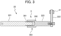
- each support member 22 has: an arm connecting part (fastenable part) 221 that is formed in a rod shape extending substantially perpendicularly to the rotation axis of the rotor 13 and is configured to be fastened to the drone 1; a guard connecting part (extension part) 222 whose distal end is mounted with the mounting part 21; and a movable part 223 whose portion adjacent to a proximal end overlaps with, and is held on the arm connecting part 221, the movable part 223 extending further outward from the arm connecting part 221 and having a distal end connected to the guard connecting part 222.
- an arm connecting part (fastenable part) 221 that is formed in a rod shape extending substantially perpendicularly to the rotation axis of the rotor 13 and is configured to be fastened to the drone 1
- a guard connecting part (extension part) 222 whose distal end is mounted with the mounting part 21
- a movable part 223 whose portion adjacent to a proximal end
- the guard parts 23 are stretched between the mounting parts 21 to connect the mounting parts 21 to each other, the mounting parts 21 being attached to the guard connecting parts 222 located at the outer ends of the six support members 22. That is, in planar view, the six (plurality of) guard parts 23 form a hexagon (polygon), and all of the plurality of rotors 13 are located inside the hexagon.
- the direction along the longitudinal direction of the guard parts 23, that is, the direction along the circumferential direction of the entire drone guard 2 will be defined as the "stretching direction”.
- Each tension adjusting mechanism 3 is configured to adjust the overlap length between the guard connecting part 223 and the arm connecting part 221, the guard connecting part 223 holding, on a distal end side thereof, the guard parts 23 via the guard connecting part 222 and the mounting part 21.
- the tension adjusting mechanism 3 has an outer thread 301 that is formed on a distal end portion of the arm connecting part 221, and a socket portion 303 that is provided in a proximal end portion of the movable part 223 and has an inner thread 302 engageable with the outer thread 301.
- the tension adjusting mechanism 3 With the tension adjusting mechanism 3, a length in which the inner thread 302 of the socket portion 303 engages with the outer thread 301 can be adjusted, whereby the distance from the center of the body 11 to the distal end portion of the support member 22 (guard connecting part 222), and thus, to the mounting part 21 held there can be changed.
- the tension adjusting mechanism 3 can adjust the distance between adjacent ones of the mounting parts 21, and consequently, can adjust a tension applied to the associated guard parts 23 in the stretching direction.
- moving the distal end portion of the support member 22 (the guard connecting part 222) on a straight line passing through the center of the body 11 makes it possible to evenly adjust the tension applied to the guard parts 23 disposed on both sides of the guard connecting part 222 with efficiency.
- the guard parts 23 remain at the same height when the tension is adjusted by the tension adjusting mechanism 3.
- the guard parts 23 are held at a height close to the rotors 13, thereby protecting the rotors 13 easily and reliably.
- the tension adjusting mechanism 3 may have a separate structure for fastening the movable part 223 to the arm connecting part 221. Examples of the separate structure include a lock nut that is engaged with the outer thread 301 to abut against the end surface of the socket portion 303.
- Each arm connecting part 221 of the present embodiment has, in a portion adjacent to the proximal end thereof, a rotation mechanism 225, and is rotatable with respect to the distal end portion of the associated arm 12. Therefore, the drone 1 can be carried while being in a state where the support members 22 are folded.
- the drone 1 is brought into a state where the arm connecting parts 221 of the support members 22 extend straight and coaxially with the arms 12 (hereinafter, this state is referred to as the use state of the support members 22).
- the movable part 223 that is provided between the arm connecting part 221 and the guard connecting part 222 is a member via which the distance between the arm connecting part 221 and the guard connecting part 222 can be adjusted.
- the guard connecting parts 222 are parts connected to the drone guard 2. Each guard connecting part 222 is connected to an end portion (hereinafter, referred to as the outer end portion) of the associated arm connecting part 221, the end portion being opposite to the inner end portion. In the use state of the support members 22, the longitudinal direction of the guard connecting parts 222 is directed upward. Thus, since the support members 22 have the guard connecting parts 222 extending substantially parallel to the rotation axes of the rotors 13, the height of the drone guard 2 can be easily adjusted. As a result, the guard parts 23 can be supported while being prevented from contacting with the rotors 13.
- the guard parts 23 prevent a principal portion of the drone 1 from colliding with buildings and trees.
- the guard parts 23 are preferably arranged to surround the rotors 13 to prevent the rotors 13 from colliding directly with buildings and trees.
- the guard part 23 may be constituted by a rope-like or wire-like flexible material. It is however preferable that the guard part 23 be constituted by an elongated band-shaped member made of a flexible and elastic material, examples of which include carbon fiber composite materials such as carbon fiber reinforced plastics (CFRP). In other words, it is desirable that the guard part 23 be produced by molding a material having a certain elastic modulus into a band shape having a small thickness, and thereby configured as a member that has a flexibility allowing bending deformation in the thickness direction while having a sufficient stiffness in the width direction.
- the term "band shape” as used herein means a shape having an average width that is five times or more as large as an average thickness. Note that the average width and the average thickness shall be calculated without taking account of a structure for connection to the guard connecting parts 222 and a structure that may be provided between the guard connecting parts 222 for a different purpose (not included in the present embodiment).
- the guard parts 23 are preferably supported such that the thickness direction thereof is substantially perpendicular to the rotation axes of the rotors 13.
- the guard part 23 can cushion the impact by contacting with the other object at a plane thereof, thereby making it possible to reduce damage to the other object.
- the guard parts 23, which are arranged such that the thickness direction thereof is substantially perpendicular to the rotation axes of the rotors 13, resist flexure in a direction (vertical direction) parallel to the rotation axes of the rotors 13. That is, in the guard part 23, a flexural vibration (vertical shaking) in a direction parallel to the rotation axis of the rotor 13 is less likely to occur than a flexural vibration (horizontal shaking) in a direction (horizontal direction) perpendicular to the rotation axis of the rotor 13.
- the guard parts 23 can be arranged close to the rotors 13 as viewed in the radial direction of the rotation axes of the rotors 13, thereby enabling the drone guard 2 to protect the rotors 13 more reliably. Further, an arrangement is conceivable in which, for example, the guard parts 23 are each arranged in a gap between the rotor 13 and the arm 12 in order to protect only the body 11, that is, the guard parts 23 are arranged to overlap with the rotors 13 in planar view. Also with this arrangement, the guard parts 23 can be prevented from contacting with the rotors 13. This effect of preventing contact between the guard parts 23 and the rotors 13 is particularly advantageous when the guard parts 23 become relaxed with a decrease in the tension due to aging or some abnormality.
- Arranging the guard parts 23 close to the rotors 13 as viewed in the radial direction of the rotation axes of the rotors 13 makes it possible to reduce the height and the horizontal projection area of the entire flight equipment F, while preventing the contact between the guard parts 23 and the rotors 13. This contributes to improvement of mobility of the flight equipment F and reduction of air resistance of the flight equipment F.
- the drone guard 2 can be in two states, namely, a use state shown in FIG. 1 in which the drone guard 2 is in use to protect the rotors 13 when the drone 1 flies; and a non-use state (not shown) in which the drone guard 2 is not used while the drone 1 is being carried by a user or is in storage.
- a use state shown in FIG. 1 in which the drone guard 2 is in use to protect the rotors 13 when the drone 1 flies
- a non-use state not shown
- a user or any other person brings the support members 22 into the use state such that the longitudinal direction of each arm connecting part 221 coincides with the horizontal direction, as shown in FIG. 1 . While maintaining this state as it is, the user fastens the mounting parts 21 to the guard connecting parts 222 of the support members 22.
- the tension adjusting mechanisms 3 are each in a state where the outer screw 301 is deeply engaged with a nut 226, so that the distal end portions of the support members 22 come close to the center of the body 11.
- the distance between the guard connecting parts 222 is slightly reduced.
- the user can attach the mounting parts 21 to the guard connecting parts 222 while the guard parts 23 are relaxed.
- the tension adjusting mechanisms 3 the user moves the distal end portions of the support members 22 away from the center of the body 11 so as to increase the distance between the mounting parts 21, thereby applying a tension to the guard parts 23.
- the application of the tension to the guard parts 23 by the tension adjusting mechanisms 3 results in application of an internal stress to the guard parts 23, the internal stress acting in a tensile direction.
- the application of the internal stress to the guard parts 23 in this manner makes the influence of an external force relatively small, thereby making it less likely for the guard parts 23 to experience further deformation, i.e., a vibration.
- the flexural vibration of the guard parts 23 can be considered as a vibration of a string.
- Application of a tension to the guard part 23 increases a speed of sound (propagation speed of vibration) in the guard part 23, and consequently, increases the natural frequency of the guard part 23.
- the vibration of the guard part 23 is mainly caused by a wind generated by the rotation of the rotor 13, the vibration has a relatively large number of low-frequency components.
- the primary mode vibration frequency that can cause the guard part 23 to vibrate relatively widely is a particularly low frequency.
- increasing the natural frequency by the application of a tension to the guard part 23 enables efficient reduction of the flexural vibration of the guard part 23.
- the user adjusts the tension adjusting mechanisms 3 of the six support members 22 so that an appropriate tension is applied to each of the six guard parts 23.
- the work of mounting the drone guard 2 to the drone 1 is completed.
- the guard parts 23 are stretched radially symmetrically in a hexagonal shape around the drone 1.
- the guard parts 23 are preferably arranged to be held at a height where the guard parts 23 do not overlap with the rotors 13 as viewed in the radial direction of the rotation axes of the rotors 13. As a result, the guard parts 23 are prevented from contacting with the rotors 13 even when a horizontal flexural vibration occurs in the guard parts 23.
- the rotors 13 are held to be positioned above the body 11 as in the present embodiment, it is more preferable to hold the drone guard 2 at a position higher than the rotors 13. With this configuration, when the flight equipment F descends, the legs 15 arranged below the body 11 and the rotors 13 can prevent damage to the body 11 and the rotors 13. When the flight equipment F ascends, the drone guard 2 arranged at a position as high as, or higher than the rotors 13 can effectively prevent damage to the body 11 and the rotors 13.
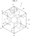
- FIG. 4 is a schematic planar view showing an exemplary configuration of a drone guard 2a as a protective member and flight equipment Fa according to an embodiment different from that shown in FIG. 1 .
- the components common to or similar to those of the embodiment described above are denoted by the same reference characters, and the detailed description thereof may be omitted.
- the flight equipment Fa includes a drone (aerial vehicle) 1 and a drone guard (protective member) 2a mounted to the drone 1.
- the drone guard 2a is per se a protective member according to an embodiment of the present invention.
- the drone guard 2a includes: a plurality of support members 22a connectable to the drone 1; a guard part (flexible member) 23a that is stretched between distal end portions of the plurality of support members 22a and 122 (one support member 22a and five support members 122), so as to surround at least a body 11 in planar view; and mounting parts 21a attached to the distal end portions of the support members 22a and holding the guard part 23a.
- the guard part 23a formed in a single endless loop is supported by the six support members 22a and 122. Further, in the drone guard 2a of the present embodiment, only the single support member 22a has a tension adjusting mechanism 3a, whereas the other support members 122 have no means for changing a distance from the center of the body 11 to the distal end portions thereof.
- the guard part 23a may be constituted by a material formed into a seamless loop shape, or by a member with a certain length formed into a loop shape by having its both ends connected together with a joint 231, as shown in the figure.
- each mounting part 21a is configured to support the guard part 23a such that the guard part 23a is movable in a length direction thereof.
- each mounting part 21a can be configured to have, for example, a holder ring 211 which is disposed outside with respect to the support member 22, and through which the guard part 23a passes.
- the support member 22a provided with the tension adjusting mechanism 3a has: an arm connecting part (fastening part) 221a that is formed in a rod shape extending substantially perpendicularly to the rotation axis of a rotor 13; a movable part 223a pivotably connected to a distal end portion of the arm connecting part 221a (in FIG. 4 , the two-dot chain lines indicate the movable part 223a in a pivoted state); and a guard connecting part (extension part) 222 that extends substantially parallel to the rotation axis of the rotor 13 from a distal end portion of the movable part 223a and has a distal end portion mounted with the mounting part 21.
- the tension adjusting mechanism 3a is configured to adjust an angle formed by the movable part 223a with the arm connecting part 221a, the movable part 223a holding, on a distal end side thereof, the guard part 23a via the guard connecting part 222 and the mounting part 21a.
- the distal end portion of the support member 22a can be relatively easily moved by a large amount.
- the guard part 23a can receive a sufficient tension applied thereto in a use state, and can be sufficiently relaxed in a non-use state.
- the tension adjusting mechanism 3a may pivot the movable part 223 (for example, in the vertical direction around a horizontal axis) so as to move the distal end portion of the support member 22a in an optional direction. It is preferable, however, that the tension adjusting mechanism 3a be configured to pivot the movable part 223a so as to move the distal end portion of the support member 22a in a plane perpendicular to the rotation axis of the rotor 13, i.e., to pivot the movable part 223a about an axis parallel to the rotation axis of the rotor 13.
- Pivoting the movable part 223a around the axis parallel to the rotation axis of the rotor 13 does not cause the motion of the tension adjusting mechanism 3a to change the height of the guard part 23a, thereby enabling the support member 22a to be easily brought into the use state.
- the tension adjusting mechanism 3a can be configured to have: a fastened side lever 311 that projects in the horizontal direction from a side surface of a vicinity of the distal end of the arm connecting part 221a; a movable side lever 312 that projects along the fastened side lever 311 from a side surface of a vicinity of the proximal end of the movable part 223a; and an adjusting screw 313 that fixes a distance between the distal end of the fastened side lever 311 and the distal end of the movable side lever 312.
- the tension adjusting mechanism 3a may have an optional configuration, such as a lock nut for fastening the adjusting screw 313, which can fix an angle formed by the movable part 223a with the arm connecting part 221a in a state where a suitable tension is applied to the guard part 23a.
- the present embodiment also allows the user or any other person to easily attach and detach the drone guard 2 by relaxing the guard part 23a by means of the tension adjusting mechanism 3a, and to properly protect the drone 1 in the use state by causing the tension adjusting mechanism 3a to apply a tension to the guard part 23a.
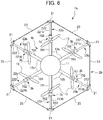
- FIG. 6 is a schematic planar view showing an exemplary configuration of a drone guard 2b as a protective member and flight equipment according to an embodiment different from those shown in FIGS. 1 and 4 .
- the flight equipment Fb includes a drone (aerial vehicle) 1b and a drone guard (protective member) 2b mounted to the drone 1b.
- the drone 1b is per se an aerial vehicle according to an embodiment of the present invention.
- the drone 1b includes a body 11, arms 12b, and a plurality of rotors 13.
- the drone guard (protective member) 2b includes: a plurality of support members 22b connectable to the drone 1b; guard parts (flexible members) 23 that are stretched between distal end portions of the plurality of support members 22b so as to surround at least a body 11 in planar view; and mounting parts 21 attached to the distal end portions of the support members 22b and holding the guard parts 23.
- the drone 1b has tension adjusting mechanisms 3b each configured to adjust the length of an associated one of the arms 12b.
- Each tension adjusting mechanism 3b is disposed on the associated arm 12 so as to be closer to the distal end of the arm 12 (closer to the outside) than the portion holding the associated rotor 13 is.
- each tension adjusting mechanism 3b adjusts the length of the associated arm 12b, and consequently, changes the distance from the center of the body 11 to the distal end portion of the associated support member 22b, thereby enabling adjustment of a tension applied to the guard parts 23 in the stretching direction.
- Each support member 22b of the present embodiment is composed of an arm connecting part 221b connectable to the arm 12b, and a guard connecting part 222 attached to the distal end portion of the arm connecting part 221b, while having no movable part.
- the tension adjusting mechanism 3b can be specifically configured by the arm 12b that has an arm body 701 extending from the body 11, and a movable end portion 702 which is attached, in a projectable and retractable manner, to the distal end of the arm body 701 toward the outside in the horizontal direction, and to which the support member 22b is connected.
- the arm 12b that has an arm body 701 extending from the body 11, and a movable end portion 702 which is attached, in a projectable and retractable manner, to the distal end of the arm body 701 toward the outside in the horizontal direction, and to which the support member 22b is connected.
- engagement with a screw is applicable.
- the present embodiment also allows the user or any other person to easily attach and detach the drone guard 2b by relaxing the guard parts 23 by means of the tension adjusting mechanisms 3b, and to properly protect the drone 1b in the use state by causing the tension adjusting mechanisms 3b to apply a tension to the guard parts 23.
- the protective member and the flight equipment according to each embodiment of the present invention do not have to include the dedicated flexible member, and may be used with a flexible member provided separately by the user.
- Examples of general-purpose articles usable as the flexible member include various ropes and wires, resin bands and metal bands for packaging or binding, etc.
- the aerial vehicle and the flight equipment according to each embodiment of the present invention may include a tension adjusting mechanism that changes the angles of the support members by pivoting distal end portions of the arms of the drone (and thus, the support members connected to the distal end portions).
- the number of the support members for supporting the flexible member(s) is not limited to six, but can be any number equal to or greater than three.
- the number of the tension adjusting mechanisms can be any number equal to or greater than one. However, since associating a plurality of tension adjusting mechanisms with one support member results in an unnecessarily complicated configuration, it is preferable to limit the number of the tension adjusting mechanisms to the number of the support members.
- the protective member and the mounting parts of the flight equipment of each embodiment of the present invention may be integral with the extension parts. Further, the mounting part configured not to fasten the flexible member thereto may have a pulley, a guide groove or the like for guiding the flexible member, in place of the holder ring.
- the configuration has been described in which the tension adjusting members are provided at both ends of the guard part.
- the present invention is not limited to this configuration.
- a configuration is conceivable in which one tension adjusting member (tension applying part) is disposed only at one end in the stretching direction of the flexible member, and the other end in the stretching direction is simply fastened. Also in this configuration, the one end of the flexible member is pulled, thereby bringing the flexible member into a tense state.
- the protective member and the flight equipment according to each embodiment of the present invention may further include a mechanism that adjusts a tension applied to the flexible member without moving the distal end portion of the support member.
- a mechanism that adjusts a tension applied to the flexible member without moving the distal end portion of the support member examples include a mechanism that adjusts the tension by moving an end of the flexible member in the stretching direction.
- the flexible member(s) does not have to be stretched planarly, but may be stretched three-dimensionally.
- the protective member and the flight equipment according to each embodiment of the present invention may further include, in addition to the support members connected so as to extend horizontally outwardly with respect to the aerial vehicle, support members connected so as to extend vertically with respect to the aerial vehicle, and a flexible member stretched between the distal end portions of the support members so as to protect the aerial vehicle from vertical impacts.
- an additional flexible member may be stretched in a shape (e.g., a triangle, a trapezoid, an arch shape, etc.) that covers an upper portion of the body in side view.
- the drone is exemplified as the aerial vehicle.
- the aerial vehicle is not particularly limited to the drone, and any aerial vehicle including a manned aerial vehicle may be employed suitably.
- the embodiments of the present invention achieve advantageous effects due to the following configurations.
- Flight equipment includes: an aerial vehicle (e.g., a drone 1, 1a, 1b) having a body (e.g., a body 11) and at least one rotor (e.g., a rotor 13) held on the body; and a protective member having a plurality of support members (e.g., support members 22, 22a, 22b) that are connected to the aerial vehicle and have a flexible member (e.g., a guard part 23) stretched between distal end portions thereof so as to surround an outside of the body.
- an aerial vehicle e.g., a drone 1, 1a, 1b
- a protective member having a plurality of support members (e.g., support members 22, 22a, 22b) that are connected to the aerial vehicle and have a flexible member (e.g., a guard part 23) stretched between distal end portions thereof so as to surround an outside of the body.
- the aerial vehicle or the protective member has a tension adjusting mechanism (e.g., a tension adjusting mechanism 3, 3a, 3b) that is capable of adjusting a tension applied to the flexible member in a stretching direction, by changing a distance from a center of the body to the distal end portion of at least one of the plurality of support members.
- a tension adjusting mechanism e.g., a tension adjusting mechanism 3, 3a, 3b
- the flexible member is maintained under a strong tension through adjustment of the tension adjusting mechanism so that the flexible member can effectively absorb an impact.
- the flexible member In a non-use state, the flexible member can be easily deformed into a desired shape.
- the user or any other person uses a dedicated case to carry flight equipment. The user can deform the flexible member in conformity with the size of the dedicated case, and can carry the protective member together with the aerial vehicle.
- fight equipment can be achieved to which a protective member is easily mounted and which is easy to carry.
- At least one of the plurality of support members may have: a fastenable part (e.g., an arm connecting part 221) that is configured to be fastened to the aerial vehicle; and a movable part (e.g., a movable part 223) that has a proximal end portion overlapping with, and held on, the fastenable part, and has a distal end portion holding the flexible member, and the tension adjusting mechanism may be configured to adjust an overlap length between the movable part and the fastenable part.
- a fastenable part e.g., an arm connecting part 221
- a movable part e.g., a movable part 223
- the tension adjusting mechanism may be configured to adjust an overlap length between the movable part and the fastenable part.
- the tension adjusting mechanism may be configured as a mechanism for engaging the movable part with the fastenable part. This feature makes it possible to accurately and easily adjust the tension applied to the flexible member, while the tension adjusting mechanism has a relatively simple structure.
- At least one of the plurality of support members may have: a fastenable part (e.g., an arm connecting part 221a) that is configured to be fastened to the aerial vehicle; and a movable part (e.g., a movable part 223a) that has a proximal end portion pivotably connected to a distal end portion of the fastenable part and has a distal end portion holding the flexible member, and the tension adjusting mechanism may be configured to adjust an angle formed by the movable part with the fastenable part.
- This feature makes it possible to move the distal end portion of the support member by a relatively large amount, thereby enabling the tension applied to the flexible member to be changed significantly.
- the tension adjusting mechanism may move the distal end potion of the support member in a plane perpendicular to a rotation axis of the rotor.
- the protective member may further include a band-shaped flexible member that is stretched between the distal end portions of the plurality of the support members.
- the flexible member has appropriate properties, thereby ensuring the protection of the rotor and the other components.
- a thickness direction of the flexible member may be perpendicular to the rotation axis of the rotor. In case where the flight equipment accidentally collides with an object, this feature contributes to reduction of damage to the object.
- An aerial vehicle (e.g., a drone 1b) includes: a body (e.g., a body 11); and at least one rotor (e.g., a rotor 13) held on the body, the aerial vehicle being adapted to be mounted with a plurality of support members that have a flexible member (e.g., a guard part 23) stretched between distal end portions thereof so as to surround an outside of the body.
- the aerial vehicle includes a tension adjusting mechanism (e.g., a tension adjusting mechanism 3b) that is capable of adjusting a tension applied to the flexible member in a stretching direction, by changing a distance from a center of the body to the distal end portion of at least one of the plurality of support members.
- the flexible member is maintained under a strong tension through adjustment of the tension adjusting mechanism so that the flexible member can effectively absorb an impact.
- the flexible member In a non-use state, the flexible member can be easily deformed into a desired shape.
- fight equipment can be achieved to which a protective member is easily mounted and which is easy to carry.
- a protective member mountable to an aerial vehicle (e.g., a drone 1, 1a) having a body (e.g., a body 11) and at least one rotor (e.g., a rotor 13) held on the body includes: a plurality of support members (e.g., support members 22, 22a) that are connectable to the aerial vehicle and have a flexible member (e.g., a guard part 23, 23a) stretched between distal end portions thereof so as to surround an outside of the body, wherein at least one of the plurality of support members has a tension adjusting mechanism (e.g., a tension adjusting mechanism 3, 3a) that is capable of adjusting a tension applied to the flexible member in a stretching direction, by changing a distance from a center of the body to the distal end portion.
- a tension adjusting mechanism e.g., a tension adjusting mechanism 3, 3a
- the flexible member is maintained under a strong tension through adjustment of the tension adjusting mechanism so that the flexible member can effectively absorb an impact.
- the flexible member In a non-use state, the flexible member can be easily deformed into a desired shape.
- a protective member can be achieved which is easy to carry while ensuring enhanced mountability to an aerial vehicle such as a drone.
- the following reference embodiment has a mechanism that adjusts a tension applied to a flexible member without moving the distal end of a support member.
- FIG. 7 is a perspective view showing an exemplary configuration of a drone mounted with a rotor guard 2c according to the reference embodiment.
- FIG. 8 is a schematic planar view of the drone 1 of FIG. 7 . Note that FIG. 8 shows the drone 1 schematically as compared with FIG. 7 , while omitting part of the configuration of the drone 1.
- the drone 1 flies while having the rotor guard 2c mounted thereto.
- the rotor guard 2c is configured to be mounted to the drone 1, and functions as a protective member for preventing rotors 13 and other components from colliding directly with buildings and trees during flight of the drone 1, and for protecting the drone 1 from external impacts.
- the drone 1 of the present reference embodiment includes a body 11, arms 12, rotors 13, support members 22c, and the rotor guard 2c.
- the body 11 incorporates an electronic device (not shown) for executing various kinds of control processing required for flight and other operations of the drone 1.
- the electronic device is a computer that controls a motor for driving the rotors 13, transmits and receives signals to and from external devices such as a controller operated by an operator of the drone 1 (hereinafter may be referred to also as the "user"), and performs processing based on information from various sensors such as a camera (not shown) provided on the body 11.
- the lower surface of the body 11 is provided with, for example, legs 15 that come into contact with the landing plane and a holder frame 17 that holds a box 16 for accommodating a delivery target.
- Each arm 12 is formed in a rod shape extending in the horizontal direction.
- One of the end portions of the arm 12 is connected to the body 11, and the other (hereinafter, referred to as the distal end portion) is provided with the rotor 13.
- the six (plurality of) arms 12 extend radially and symmetrically from the body 11 in planar view. The six arms 12 are equally spaced apart from each other in a circumferential direction.
- Each rotor 13 is rotatably provided on an upper surface of the distal end portion of an associated one of the arms 12.
- the rotors 13 are mounted to the arms 12 such that their planes of revolution coincide with a horizontal plane.
- each of the six arms 12 is provided with the rotor 13.
- the six rotors 13 in total of the drone 1 rotate to generate lift for the drone 1 to fly.
- the support members 22c are usable to mount the rotor guard 2c to the drone 1.
- the distal end portion of each of the six arms 12 is provided with the support member 22c.
- six support members 22c in total hold the rotor guard 2c.
- Each of the six support members 22c of the present reference embodiment includes: an arm connecting part 221c formed in a rod shape; and a guard connecting part 222 formed in an elongated flat plate shape.
- the guard connecting part 222 is connected to one end portion of the arm connecting part 221c.
- the support member 22c has a substantial L-shape as a whole.
- the arm connecting part 221c is connectable to the distal end portion of the arm 12.
- the arm connecting part 221c of the present reference embodiment has, at one end portion (hereinafter, referred to as the inner end portion), a rotation mechanism 225, and is rotatable with respect to the distal end portion of the arm 12. Therefore, the drone 1 can be carried in a state where the support members 22c are folded. To use the drone 1, as shown in FIG. 1 , the drone 1 is brought into a state where the arm connecting parts 221c of the support members 22c extend in the horizontal direction (hereinafter, this state is referred to as the use state of the support members 22c).
- the guard connecting parts 222 are parts connected to the rotor guard 2c. Each guard connecting part 222 is connected to an end portion (hereinafter, referred to as the outer end portion) of the associated arm connecting part 221c, the end portion being opposite to the inner end portion. In the use state of the support members 22c, the longitudinal direction of the guard connecting parts 222 is directed upward.
- the rotor guard 2c As schematically shown in FIG. 2 , the rotor guard 2c is provided outside the rotors 13 as viewed from the body 11 of drone 1.
- the term “outside” means a side away from the rotors 13 in both stationary and rotating states as viewed in planar view when the center of gravity or the center of the body 11 of the drone 1 is defined as the base point.
- the "outside” can also be expressed as radially outward while the base point is set to be the center of a sphere.
- the rotor guard 2c is arranged to surround the rotors 13, whereby the rotors 13 are prevented from colliding directly with buildings and trees.
- the rotor guard 2c is disposed at the same height as the rotors 13 or at a position higher than the rotors 13. According to the drone 1 of the present reference embodiment, when the drone 1 descends, the legs 15 arranged below the body 11 and the rotors 13 can prevent damage to the rotors 13, and when the drone 1 ascends, the rotor guard 2c, which is positioned at the same height as the rotors 13 or at a position higher than the rotors 13, can effectively prevent damage to the rotors 13.
- the rotor guard 2c includes: a plurality of guard parts (flexible members) 23 that are stretched around the drone 1 in planar view; and a plurality of tension adjusting members 5 that can adjust a tension applied to the guard parts 23.
- Each guard part 23 is configured as an elongated band-shaped member made of a flexible and elastic material, examples of which include carbon fiber composite materials such as carbon fiber reinforced plastics (CFRP). As shown in FIG. 2 , the guard parts 23 are stretched so as to connect the guard connecting parts 222 to each other, the guard connecting parts 222 being located at the outer ends of the six support members 22c. That is, in planar view, the six (plurality of) guard parts 23 form a hexagon (polygon), inside which all of the plurality of rotors 13 are located. In the following description, the direction along the longitudinal direction of the guard parts 23, that is, the direction along the circumferential direction of the entire rotor guard 2c will be defined as the "stretching direction".
- Each tension adjusting member 5 is made of a deformable material, examples of which include an aluminum alloy subjected to anodizing. Note that the tension adjusting member 5 may be made of an elastically deformable resin material.
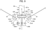
- FIG. 9 is a planar view showing the tension adjusting member 5 of the rotor guard 2c of the present reference embodiment.
- the tension adjusting member 5 has a shape symmetrical about a vertical dash-dot line C in FIG. 9 .
- the vertical dash-dot line C in FIG. 9 is a virtual straight line passing through the center of the tension adjusting member 5 in planar view.
- the tension adjusting member 5 of the present reference embodiment includes: a mounting part 21c to which the guard connecting part 222 of the support member 22c is fixed; a tension applying part 120 to which the guard parts 23 are connected; and a tension adjusting part 100 to which an adjusting bolt 200 is fastened, the adjusting bolt 200 being usable to adjust the tension applied to the guard parts 23 by the tension applying part 120.
- the mounting part 21c, the tension applying part 120 and the tension adjusting part 100 are integrally formed into a shape in which deformations of the respective parts interact with each other.
- the mounting part 21c has a fitting hole 130 in which an end portion of the support member 22c (guard connecting part 222) is fixed.
- the fitting hole 130 has a rectangular shape in planar view, and penetrates the mounting part 21c in the vertical direction.
- the fitting hole 130 is in such a positional relationship that the fitting hole 130 is interposed between the tension applying parts 120A and 120B in the stretching direction.
- the distal end potion of the guard connecting part 222 has a length and a width that are substantially the same as or slightly smaller than those of the fitting hole 130 in a state where the adjusting bolt 200 is not tightened.
- the tension applying parts 120A and 120B constitute both side portions of the tension adjusting member 5, respectively, and are integral with part of the inner wall of the fitting hole 130.
- the tension applying parts 120A and 120B have slits 121A and 121B, respectively. End portions of the guard parts 23 are inserted into the slits 121A and 121B. Both end portions of the guard part 23 are each formed into a connecting part 230 having a large width.
- the guard parts 23 are fastened to the tension applying part 120 through tightening a fixing screw 210A and a fixing screw 210B while having the connecting parts 230 inserted in the slits 121. It will be described later how the tension applying parts 120A and 120B operate.
- the tension adjusting parts 100A and 100B are connected to the tension applying parts 120A and 120B, respectively, while forming part of the inner walls 110A and 110B of the fitting hole 130.
- the tension adjusting parts 100A and 100B face each other while sandwiching therebetween a gap 131 which communicates with the fitting hole 130 and through which the dash-dot line C passes.
- the adjusting bolt 200 is fastened to the tension adjusting part 100B while penetrating the tension adjusting part 100A.
- the tension adjusting part 100A and the tension adjusting part 100B move to come close to each other.
- the tension adjusting part 100A and the tension adjusting part 100B move away from each other.
- the rotor guard 2c can be in two states, namely, a use state shown in FIG. 7 in which the rotor guard 2c is in use to protect the rotors 13 when the drone 1 flies; and a non-use state (not shown) in which the rotor guard 2c is not used while the drone 1 is being carried by a user or is in storage.
- a use state shown in FIG. 7 in which the rotor guard 2c is in use to protect the rotors 13 when the drone 1 flies
- a non-use state not shown
- the user or any other person brings the support members 22c into a use state such that the longitudinal direction of the arm connecting parts 221c coincides with the horizontal direction, as shown in FIG. 7 . While maintaining this state as it is, the user fastens the mounting parts 21c to the guard connecting parts 222 of the support members 22c.
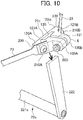
- FIG. 10 is a perspective view showing the tension adjusting member 5 that is not yet attached to the support member 22c.
- FIG. 10 shows a state in which the tension adjusting member 5 connected to the two guard parts 23 is not yet fastened to the support member 22c.
- the distal end portion of the guard connecting part 222 of the support member 22c (the outer end portion of the support member 22c) in the use state is inserted into the fitting hole 130 of the tension adjusting member 5.
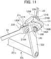
- FIG. 11 is a perspective view showing the tension adjusting member 5 that has been attached to the support member 22c.
- the adjusting bolt 200 is screwed in the tightening direction while the distal end portion of the inserted guard connecting part 222 penetrates the fitting hole 130.
- the tension adjusting member 5 tightens the fitting hole 130 and applies a tension.
- the present reference embodiment is configured such that motion of the tension adjusting parts 100A and 100B for fastening the support member 22c to the fitting hole 130 takes place in conjunction with motion of the tension applying parts 120A and 120B for applying a tension.
- the former motion and the latter motion will be described separately.
- the tension adjusting member 5 deforms such that the tension applying part 120A connected to the tension adjusting part 100A is turned in a direction away from the body 11 of the drone 1 (in an outward direction) about a fulcrum 140 as a center of rotation, while the tension applying part 120B connected to the tension adjusting part 100B is turned in a direction away from the body 11 of the drone 1 (in an outward direction) about the fulcrum 140 as the center of rotation.
- the guard parts 23 respectively connected to the tension applying parts 120A and 120B are pulled outward, whereby a tension is applied.
- the above-described motion through which the support member 22c is fastened to the fitting hole 130 and the motion through which the tension applying parts 120A and 120B apply a tension are triggered substantially simultaneously by the movement of the tension adjusting parts 100A and 100B.
- a single operation of tightening the adjusting bolt 200 causes a fastening force of the adjusting bolt 200 to be transmitted from the tension adjusting part 100 to each of the inner wall 110 and the tension applying part 120, resulting in that the tightening of the fitting hole 130 and the application of tension by the tension applying part 120 take place.
- the strength of the force tightening the fitting hole 130 and the strength of the tension applied to the tension applying part 120 can be adjusted in accordance with a degree of tightening of the inserted adjusting bolt 200.
- the mounting part 21c for mounting the rotor guard 2c functions also as the tension adjusting member 5.
- the tension adjusting member 5 is attached to each of the six support members 22c.
- FIG. 12A is a diagram schematically showing the guard part 23 before application of the tension, and the tension adjusting members 5A and 5B respectively connected to both ends of the guard part 23.
- FIG. 12B is a diagram schematically showing the guard part 23 with the tension applied thereto, and the tension adjusting members 5A and 5B respectively connected to both ends of the guard part 23.
- FIG. 12A shows a state in which the adjusting bolts 200 of the tension adjusting members 5A and 5B are yet to be tightened, and in which the guard part 23 is relatively relaxed and easily deformed by a force applied externally.
- the adjusting bolts 200 of the tension adjusting members 5A and 5B are tightened. Consequently, the tension applying part 120 of each of the tension adjusting members 5A and 5B is turned about the fulcrum 140 as the center of the rotation, in a direction away from the body 11 of the drone 1.
- the guard part 23 is pulled toward each of the tension adjusting members 5A and 5B.
- the guard part 23 is brought into the state shown in FIG. 12B .
- the mounting parts 21c of the tension adjusting members 5 are attached to all of the six support members 22c (guard connecting parts 222), and the adjusting bolt 200 of each of the tension adjusting members 5 is tightened. As a result, the guard parts 23 are stretched in the circumferential direction while a suitable tension is applied to the guard parts 23. In this way, the operation of mounting the rotor guard 2c to the drone 1 is completed.
- the rotor guard 2c of the present reference embodiment has the guard parts 23 stretched in a hexagonal shape and radially symmetrically with respect to the drone 1.
- the guard parts 23 are supported on the L-shaped support members 22c so that the guard parts 23 are positioned at the same height as the rotors 13 or higher than the rotors 13.
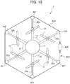
- FIG. 13 is a schematic planar view showing a drone with a rotor guard 402 of the first modification applied thereto.
- the rotor guard 402 shown in FIG. 13 includes: a plurality of engaging parts 421; one guard part 423 that is stretched between the plurality of engaging parts 421; and one tension adjusting member 405 for applying a tension to the guard part 423.
- each engaging part 421 is fixed to the outer end portions of the six support members 22c on a one-to-one basis.
- the six engaging parts 421 in total arranged on the support members 22c are all formed so as to allow the guard part 423 to move in the stretching direction (circumferential direction).
- each engaging part 421 may be configured as a slide mechanism that has a recessed peripheral surface with which the guard part 423 is engaged, and that allows the engaged guard part 423 to slide in the stretching direction in accordance with a degree of the applied tension.
- each engaging part 421 may be constituted by a rotatable roller, and the guard part 423 may be wrapped on the circumferential surfaces of the rollers. With this configuration, the guard part 423 moves in the stretching direction in accordance with a degree of the applied tension while the rollers are rotating.
- the guard part 423 is a band-shaped or linear member made of a single flexible and elastic material.
- the guard part 423 is constituted by a material such as a carbon fiber composite material or rubber.
- the single guard part 423 is wrapped on the six engaging parts 421 so as to form a hexagonal loop in planar view. All of the rotors 13 of the drone 1 are positioned inside the loop formed by the guard part 423.
- the tension adjusting member 405 is arranged on the guard part 423 between the support members 22c, and is a member separate from the engaging parts 421 fixed to the support members 22c.
- the tension adjusting member 405 is connected to both one end of the guard part 423 and the other end of the guard part 423.
- the tension adjusting member 405 applies a tension in the stretching direction to the guard part 423 by moving the one end and the other end of the guard part 423, which is stretched in a loop shape, close to each other.
- the tension adjusting member 405 of this modification has a tension adjustor (not shown) constituted by a screw mechanism or the like, and is capable of adjusting a pull-in amount of the guard part 423 by the tension adjustor.
- the tension adjusting member 405 is configured to operate such that screwing the screw mechanism of the tension adjustor in a predetermined direction increases the pull-in amount of the guard part 423, and screwing the screw mechanism in the opposite direction reduces the pull-in amount.
- the single guard part 423 forms a loop surrounding the rotors 13. Therefore, when the one end and the other end of the guard part 423 are moved to come close to each other in the stretching direction, the guard part 423 wrapped on the engaging parts 421 moves to be pulled into the tension adjusting member 405, and consequently, is brought into a state in which a tension is applied to the entire the guard part 423. Conversely, when the tension adjusting member 405 moves the one end and the other end of the guard part 423 away from each other in the stretching direction, the guard part 423 is brought into a relatively relaxed state.
- a user wraps the guard part 423 on the engaging parts 421, and thereafter, increases the pull-in amount of the guard part 423 using the tension adjusting member 405, whereby the guard part 423 is brought into a state in which a tension is applied to the guard part 423 over its entire circumference.
- the single tension adjusting member 405 applies a tension to the guard part 423 that is stretched between the plurality of engaging parts 421.
- FIG. 14 is a schematic planar view showing the drone 1 with a rotor guard 452 of the second modification applied thereto.
- the drone 1 of the second modification has a configuration in which three arms 12 extend from a body 11, and support member 22c are arranged on the arms 12 on a one-to-one basis.
- Engaging parts 453 that are similar to those of the first modification are arranged on the outer end portions of the support members 22c.
- one guard part 455 is wrapped on the engaging parts 453 so as to form a triangular loop in planar view.
- a tension adjusting member 405 of the second modification has a configuration similar to that of the first modification. That is, also in this modification, the single tension adjusting member 405 applies a tension to the guard part 455 over the entire circumference.
- the tension adjusting member 405 is provided for the single guard part 423 or 455.
- the number is not limited to one. It is conceivable to arrange a plurality of tension adjusting members 405. For example, it is possible to adopt a configuration in which each side of a hexagonal or triangular loop is provided with the tension adjusting member 405, or a configuration in which the tension adjusting members 405 are arranged in an intermittent fashion. Further, the guard part 423 or 455 may be divided into a plurality of pieces, which are then formed into a single loop, and the tension adjusting member 405 may be provided to each of the pieces of the guard part.
- FIG. 15 is a schematic planar view showing a drone 1 with a rotor guard 502 of the third modification applied thereto.
- one of three support members 22c is provided with the tension adjusting member 5 functioning also as the mounting part 21c described in the first reference embodiment.
- the other two support members 22c are provided with the engaging parts 453 described in the first and second modifications.
- the guard part 455 has one end portion fastened to one side portion (the tension applying part 120A) of the tension adjusting member 5, and the other end portion connected to the other side portion (the tension applying part 120B) of the tension adjusting member 5.
- the one end and the other end of the guard part 455 are connected to the same tension adjusting member 5.
- the tension adjusting member 5 fastening to the support member 22c and application of a tension to the guard part 455 are completed through a single operation. Therefore, along with the fastening of the tension adjusting part 5 to the support member 22c, the application of a suitable tension to the guard part 455 is completed.
- the single guard part 455 forms a triangular loop in planar view.
- the single tension adjusting member 5 can apply a tension to the guard part 455 over the entire circumference.
- the shape of the loop formed by the guard part as the flexible member is not limited to the hexagonal shape.
- the shape formed by the flexible member is not limited to the triangle described in the second and third modifications.
- the flexible member can form an appropriate shape such as a circle and a polygon having a three or more angles, example of which include a quadrangle, a pentagon, a heptagon, an octagon, etc.
- the flexible member is not necessarily limited to a configuration that is continuous around the entire circumference. A gap may be formed in a portion of the circumference of the flexible member.
- the overall shape of the rotor guard (protective member) in the use state can be appropriately changed according to the shape of the drone, the number and arrangement of the rotors.
- the number of the tension adjusting members does not need to be the same as the number of the mounting parts. It is possible to adopt a configuration in which the number of the tension adjusting members is less than the number of the mounting parts.
- a configuration can be adopted in which the guard part 455 of the third modification forms a polygonal loop having many angles, such as a hexagonal loop or a heptagonal loop, and a single tension adjusting member 5 applies a tension to the single guard part 455.
- the guard part is preferably made of a soft material. Consequently, in a case of using a material having a relatively high elasticity, a situation can be avoided where an insufficient tension is applied due to the tension adjusting members which are less in number than the mounting parts, and the guard part expands significantly outward.
- an optional number of the flexible members, an optional number of the tension adjusting members, and an optional number of the mounting parts can be arranged at optional locations.
- the protective member can have various shapes and various configurations within a scope in which the protective member having not only simple mountability but also enhanced portability can be achieved.
- the configuration in which the mounting part 21c and the support member 22c are fastened together by the adjusting bolt 200 has been described as an example.
- the present invention is not limited to this configuration.
- the adjusting bolt 200 does not have to be used, and the outer end portion of the support member 22c to be fitted into the fitting hole 130 of the mounting part 21c may be configured as a dedicated connector or the like.
- the configuration in which the fixing screw 210 is used to fasten the mounting part 21c and the guard part 23 together has been described as an example.
- a fastener such as a buckle for fastening a belt may be used in place of the fixing screw 210.
- the guard parts 23 and 423 are constituted by a flexible member, properties of which are not particularly limited.
- the flexible member may be made of a material other than the carbon fiber composite material and rubber, such as a soft resin or the like.
- the configuration in which the six guard parts 23 form one loop and the configuration in which the single guard part 423 or 455 forms one loop have been described as examples.
- the present invention is not limited to these configurations.
- a configuration may be adopted in which two or more loops each formed by one or plurality of flexible members are arranged one above the other in the vertical direction.
- the above-described reference embodiment may have a configuration in which a loop formed by a first flexible member is arranged at a position higher than the rotors 13, a loop formed by a second flexible member is arranged at substantially the same height as the rotors, and a loop formed by a third flexible member is arranged at a position lower than the rotors.
- the position, such as a height and a distance in the horizontal direction, of the flexible member with respect to the rotors can be appropriately changed depending on the circumstances.
- the configuration in which the tension applied to the guard part 23 is adjusted by the tension adjusting member that deforms in accordance with screwing of the adjusting bolt 200 or the like has been described as an example of adjustment of the tension applied to the guard part 23.
- the present invention is not limited to this configuration.
- a configuration may be adopted in which a mechanism moving in a direction away from the center of the body 11 of the drome 1 (in a radially outward direction) applies a tension to the guard part, while the body 11 is defined as the center in planer view.
- a configuration may be adopted in which movement of the tension applying part in the direction to apply a tension to the flexible member results in that the fitting hole is narrowed via a link mechanism.
- a configuration may be adopted in which a member that expands by injection of a fluid such as air is provided to cause motion of the tension applying part and that of the fitting hole to take place in conjunction with each other.
- the support member 22c that is rotatable with respect to the arm 12 has been described as an example.
- the support member may be configured as a member retractable in the arm, a member detachable from the arm, or a member integral with the arm.
- the protective member may include the support member.
- the mounting part 21c and the support member 22c may be integral with each other.
- the above-described reference embodiment and modification may additionally include an adjustment mechanism that can adjust the horizontal length of the arm 12, the horizontal length of the support member 22c, and the height of the support member 22c. It is necessary that the rotors 13 can freely rotate without contacting with the rotor guard 2c and that the rotor guard 2c is mounted to the drone 1 and positioned so as to properly protect the rotors 13. With this modification, a single type of protective member can be applied to drones in different sizes.
- both end portions of the guard part are each provided with the tension adjusting member.
- the tension adjusting member tension applying part
- the tension adjusting member may be provided only at one end portion of the flexible member in the stretching direction, and the other end portion in the stretching direction may be simply fastened. Also with this configuration, the one end portion of the flexible member is pulled, whereby the flexible member is brought into a tense state.
- the protective member is configured as the rotor guard mountable to the drone 1.
- the target to be mounted with the protective member is not particularly limited to the drone 1.
- the protective member is suitably mounted to aerial vehicles including a manned aerial vehicle.
- a protective member e.g., a rotor guard 2c, 402, 502 for an aerial vehicle (e.g., a drone 1) having at least one rotor (e.g., a rotor 13) is supported on support members (e.g. support members 22c) that are connectable to the aerial vehicle, and includes: a flexible member (e.g., a guard part 23, 423, 455) that is stretched to surround an outside of the at least one rotor in planar view; and a tension adjusting member (e.g., a tension adjusting member 5, 405) that is capable of adjusting a tension applied to the flexible member in a stretching direction.
- a flexible member e.g., a guard part 23, 423, 455
- a tension adjusting member e.g., a tension adjusting member 5, 405
- the flexible member is maintained under a strong tension through adjustment of the tension adjusting member so that the flexible member can effectively absorbs an impact.
- the flexible member can be easily deformed into a desired shape.
- a user or the like uses a dedicated case to carry the drone 1 as the aerial vehicle.
- the user can deform the guard part 23 in conformity with the size of the dedicated case, and can carry the protective member together with the drone 1.
- the protective member e.g., the rotor guard
- the protective member can be achieved which is easy to carry while ensuring enhanced mountability to the aerial vehicle such as the drone.
- the protective member for the aerial vehicle includes mounting parts (e.g., mounting parts 21c) via which the flexible member is fastened to the support members, the mounting members each being integral with a tension adjusting member.
- the mounting part is detachable from the support member.
- the protective member with enhanced mountability can be used repeatedly in accordance with situation.
- the mounting part has a fitting hole (e.g., a fitting hole 130) into which a distal end portion of the support member is fitted.
- the tension adjusting member has a tension applying part (e.g., a tension applying part 120). Motion of the tension adjusting part to apply a tension to the flexible member takes place in conjunction with motion to narrow the fitting hole. Thus, the application of the tension to the flexible member and the fastening of the support member to the fitting hole can be completed by a single operation.
- the tension adjusting member has a tension adjusting part (e.g., a tension adjusting part 100) which is integral with the tension applying part and an inner wall (e.g., an inner wall 110) of the fitting hole, which is deformable, and to which a fastening member is fastened.
- a tension adjusting part e.g., a tension adjusting part 100
- an inner wall e.g., an inner wall 110
- a fastening member e.g., an adjusting bolt 200
- the tension adjusting part moves, and the movement of the tension adjusting part causes the tension applying part to deform in a direction to apply a tension to the flexible member and the inner wall to deform so as to narrow the fitting hole.
- the tension applying parts are provided at two locations i.e., on one side and the other side, between which the fitting hole is interposed, and are each connected to the flexible member.
- the tension adjusting parts e.g., tension adjusting parts 100A, 100B
- the tension applying parts are provided at two locations, i.e., on one side and the other side, between which a gap (e.g., a gap 131) is interposed, the gap communicating with the fitting hole.
- This movement of the tension applying parts results in application of a tension to each of the flexible members respectively connected to the tension applying parts located on both sides, and narrows the fitting hole.
- This feature makes it possible to complete the application of the tension and the tightening of the fitting hole by a single operation, and to set the tensions applied to the two flexible members in a balanced manner.
- the aerial vehicle includes: a body (e.g., a body 11); and a plurality of arms (e.g., arms 12) extending from the body. An end portion of each support member adjacent to the body is connected to a distal end portion of the arm. The flexible member is stretched between the distal end portions of the support members such that the flexible member surrounds an outside of all the rotors. Even if the rotors are positioned away from the body, this feature allows the flexible member to be stretched outside the plurality of rotors without interfering with the rotors.
- the flexible member In the vertical direction, the flexible member is stretched at the same height as the rotors or at a position higher than the rotors.
- This feature can effectively prevent the rotors from contacting directly with buildings or trees. In particular, when the aerial vehicle ascends, this feature can effectively prevent damage to the rotors provided with no protective member located above the rotors.
- the flexible member is elastic. This feature allows the protective member to have mountability and impact absorption at a high level. Further, elastic deformation can release an impact given at the time of collision. Therefore, constituting the flexible member by an elastic material can lower a strength intended for the flexible member from the viewpoint of impact resistance, and thus, provides a strength-related advantage.
- the flexible member is made of a carbon fiber composite material. With this feature, a protective member can be achieved which is lightweight and highly strong, and has a sufficient impact resistance without impairing the flight performance of the drone.
- the flexible member is slidably engaged with a plurality of engaging parts (e.g., engaging parts 421, 453) arranged in the stretching direction, and the tension adjusting member is arranged in at least one of intervals between the engaging parts.
- a single tension adjusting member can apply a tension to a large area of the flexible member over the engaging parts, thereby contributing to reduction of the total number of the tension adjusting members.
- a protective member e.g., a rotor guard 2c, 402, 502 for an aerial vehicle (e.g., a drone 1) having at least one rotor (e.g., a rotor 13) is supported on support members (e.g.
- a flexible member e.g., a guard part 23, 423, 455
- a tension applying part e.g., a tension applying part 120 of a tension adjusting member 5A
- This feature makes it possible to bring the flexible member into a tense state in which no flexure is allowed in the stretching direction, in which the flexible member resists displacement in a direction crossing the stretching direction.
- the flexible member Even if an obstacle comes into contact with the flexible member in a direction crossing the stretching direction, such as a direction perpendicular to the stretching direction in the vertical direction or in a horizontal plane, the flexible member remains in position and can reliably prevent damage to the rotors. Also with this feature, in a non-use state, the flexible member can be deformed into a desired shape.
- the protective member e.g., the rotor guard
- the protective member can be achieved which is easy to carry while ensuring enhanced mountability to the aerial vehicle.
- the protective member for the aerial vehicle further includes a second tension applying part (e.g., a tension applying part 120 of a tension adjusting member 5B) that is connected to the other end portion of the flexible member in the stretching direction and pulls the flexible member supported on the support members toward the other end portion in the stretching direction.
- a second tension applying part e.g., a tension applying part 120 of a tension adjusting member 5B
- a strong tension can be applied to the flexible member in a balanced manner. This contributes to further enhancement of the resistance of the flexible member to deformation.
Landscapes
- Engineering & Computer Science (AREA)
- Aviation & Aerospace Engineering (AREA)
- Mechanical Engineering (AREA)
- Remote Sensing (AREA)
- Toys (AREA)
- Structures Of Non-Positive Displacement Pumps (AREA)
Abstract
Description
- The present invention relates to flight equipment, an aerial vehicle and a protective member for such an aerial vehicle.
- Aerial vehicles such as drones have been conventionally known which freely move in midair with the help of lift generated by rotation of rotors thereof. The rotor of an aerial vehicle of this type can be damaged by contact that may be caused when the aerial vehicle collides with a tree or a building due to maneuvering by the user or influence of wind, or when the aerial vehicle makes an emergency landing on the ground. Since such damage to the rotor may hinder flight, a technique to equip an aerial vehicle with a protective member for preventing the rotor from being damaged or distorted by an external impact has been proposed (see, for example, Patent Document 1).
- Patent Document 1: Japanese Patent No.
6245566 - However, known techniques including the technique disclosed in
Patent Document 1 assign importance to only the protection of the rotors, and have room for improvement from the viewpoints of mountability of the protective member to an aerial vehicle and portability of flight equipment including the protective member. - One or more embodiments of the present invention has been achieved in view of the foregoing background, and is intend to achieve an object of providing a protective member, an aerial vehicle and flight equipment that are easy to carry, while ensuring enhanced mountability to the aerial vehicle.
- To achieve the above object, flight equipment according to an aspect of the present invention includes: an aerial vehicle having a body and at least one rotor held on the body; and a protective member having a plurality of support members that are connected to the aerial vehicle and have a flexible member stretched between distal end portions thereof so as to surround an outside of the body, wherein the aerial vehicle or the protective member has a tension adjusting mechanism that is capable of adjusting a tension applied to the flexible member in a stretching direction, by changing a distance from a center of the body to the distal end portion of at least one of the plurality of support members.
- Another aspect of the present invention is directed to an aerial vehicle including: a body; and at least one rotor held on the body, wherein the aerial vehicle is adapted to be mounted with a plurality of support members that have a flexible member stretched between distal end portions thereof so as to surround an outside of the body, and the aerial vehicle further includes a tension adjusting mechanism that is capable of adjusting a tension applied to the flexible member in a stretching direction, by changing a distance from a center of the body to the distal end portion of at least one of the plurality of support members.
- Yet another aspect of the present invention is directed to a protective member mountable to an aerial vehicle having a body and at least one rotor held on the body, the protective member including: a plurality of support members that are connectable to the aerial vehicle and have a flexible member stretched between distal end portions thereof so as to surround an outside of the body, wherein at least one of the plurality of support members has a tension adjusting mechanism that is capable of adjusting a tension applied to the flexible member in a stretching direction, by changing a distance from a center of the body to the distal end portion.
- The present invention provides flight equipment, an aerial vehicle and a protective member that are easy to carry, while ensuring enhanced mountability.
-
-
FIG. 1 is a perspective view showing an exemplary configuration of a protective member and flight equipment according to an embodiment of the present invention; -
FIG. 2 is a schematic planar view showing the flight equipment ofFIG. 1 ; -
FIG. 3 is a schematic cross-sectional view showing a support member of the flight equipment ofFIG. 1 ; -
FIG. 4 is a schematic planar view showing an exemplary configuration of a protective member and flight equipment according to an embodiment different from that shown inFIG. 1 ; -
FIG. 5 is a perspective view showing a support member of the flight equipment ofFIG. 4 ; -
FIG. 6 is a schematic planar view showing an exemplary configuration of a protective member and flight equipment according to an embodiment different from those shown inFIGS. 1 and4 ; -
FIG. 7 is a perspective view showing an exemplary configuration of a drone mounted with a drone guard according to a reference embodiment; -
FIG. 8 is a schematic planar view showing the drone ofFIG. 7 ; -
FIG. 9 is a schematic planar view showing a tension adjusting member of the drone guard ofFIG. 7 ; -
FIG. 10 is a perspective view showing the tension adjusting member that is not yet attached to a support member ofFIG. 7 ; -
FIG. 11 is a perspective view showing the tension adjusting member that has been attached to the support member ofFIG. 7 ; -
FIG. 12A is a diagram schematically showing a guard part before application of a tension, and tension adjusting members respectively connected to both ends of the guard part; -
FIG. 12B is a diagram schematically showing the guard part with the tension applied thereto, and the tension adjusting members respectively connected to both ends of the guard part; -
FIG. 13 is a schematic planar view showing a drone with a drone guard of a first modification applied thereto; -
FIG. 14 is a schematic planar view showing a drone with a drone guard of a second modification applied thereto; and -
FIG. 15 is a schematic planar view showing a drone with a drone guard of a third modification applied thereto. - Embodiments of the present invention will be described below with reference to the drawings. In the following description, unless otherwise noted, the plane on which a drone as an aerial vehicle lands is referred to as the "landing plane", and in particular, a direction in which the drone takes off as viewed from the landing plane is referred to as the "upward direction", while the direction opposite to the "upward direction" is referred to as the "downward direction". In addition, a distance from the landing plane in the upper direction is referred to as "height", and the "vertical direction" is defined to coincide with the upward/downward direction.
-
FIG. 1 is a perspective view showing an exemplary configuration of a protective member and flight equipment according to an embodiment of the present invention.FIG. 2 is a schematic planar view showing the flight equipment F ofFIG. 1 . Note thatFIG. 2 shows the flight equipment F schematically as compared withFIG. 1 , while omitting part of the configuration of the flight equipment F. - As shown in
FIGS. 1 and2 , the flight equipment F includes a drone (aerial vehicle) 1 and a drone guard (protective member) 2 mounted to thedrone 1. - The
drone 1 includes abody 11,arms 12, and a plurality ofrotors 13. - The
body 11 incorporates an electronic device (not shown) for executing various kinds of control processing required for flight and other operations of thedrone 1. For example, the electronic device is a computer that controls a motor for driving therotors 13, transmits and receives signals to and from external devices such as a controller operated by an operator of the drone 1 (hereinafter may be referred to also as the "user"), and performs processing based on information from various sensors such as a camera (not shown) provided on thebody 11. - The lower surface of the
body 11 is provided with, for example,legs 15 that come into contact with the landing plane and aholder frame 17 that holds abox 16 for accommodating a delivery target. - Each
arm 12 is formed in a rod shape extending in a horizontal direction. One of the end portions of thearm 12 is connected to thebody 11, and the other (hereinafter, referred to as the distal end portion) is provided with therotor 13. In the present embodiment, the six (plurality of)arms 12 extend radially and symmetrically from thebody 11 in planar view. The sixarms 12 are equally spaced apart from each other in a circumferential direction. - The
rotors 13 are held by thebody 11 via thearms 12. Specifically, eachrotor 13 is rotatably provided on an upper surface of the distal end portion of an associated one of thearms 12. Therotors 13 are mounted to thearms 12 such that their planes of revolution coincide with a horizontal plane. In the present embodiment, each of the sixarms 12 is provided with therotor 13. The sixrotors 13 in total of thedrone 1 rotate to generate lift for thedrone 1 to fly. - The
drone guard 2 prevents therotors 13 and the other components from colliding directly with buildings and trees during flight of the flight equipment F, and thereby protects thedrone 1 from external impacts. Thedrone guard 2 is per se a protective member according to an embodiment of the present invention. - The
drone guard 2 includes: a plurality ofsupport members 22 connectable to thedrone 1; guard parts (flexible members) 23 that are stretched between distal end portions of the plurality ofsupport members 22 so as to surround at least thebody 11 in planar view; and mountingparts 21 attached to the distal end portions of thesupport members 22 and holding theguard parts 23. - It is preferable that the
guard parts 23 be provided to surround an area from thebody 11 to an outside of thearms 12. As schematically shown inFIG. 2 , it is further preferable that theguard parts 23 be provided to surround an area from thebody 11 to an outside of therotors 13. Here, the term "outside" means a side away from thebody 11 when the center of gravity or center of thebody 11 of thedrone 1 is defined as the base point. The "outside" can also be expressed as radially outside while the base point is set to be the center of a sphere. - In the present embodiment, the six
support members 22 are connected to the distal end portions of the sixarms 12, and theguard parts 23 are each stretched between the distal end portions of the sixsupport members 22 in total. Eachsupport member 22 has atension adjusting mechanism 3 that can adjust a tension applied to theguard parts 23 in a stretching direction, by changing a distance from the center of thebody 11 to the distal end portion of thesupport member 22. Specifically, eachsupport member 22 has: an arm connecting part (fastenable part) 221 that is formed in a rod shape extending substantially perpendicularly to the rotation axis of therotor 13 and is configured to be fastened to thedrone 1; a guard connecting part (extension part) 222 whose distal end is mounted with the mountingpart 21; and amovable part 223 whose portion adjacent to a proximal end overlaps with, and is held on thearm connecting part 221, themovable part 223 extending further outward from thearm connecting part 221 and having a distal end connected to theguard connecting part 222. Note that "substantially perpendicular(ly)" as used herein should be interpreted to mean that a relative angle is 85° or larger and 95° or smaller, and "substantially parallel" should be interpreted to mean that a relative angle is 5° or smaller. - As shown in
FIG. 2 , theguard parts 23 are stretched between the mountingparts 21 to connect the mountingparts 21 to each other, the mountingparts 21 being attached to theguard connecting parts 222 located at the outer ends of the sixsupport members 22. That is, in planar view, the six (plurality of)guard parts 23 form a hexagon (polygon), and all of the plurality ofrotors 13 are located inside the hexagon. In the following description, the direction along the longitudinal direction of theguard parts 23, that is, the direction along the circumferential direction of theentire drone guard 2 will be defined as the "stretching direction". - Each
tension adjusting mechanism 3 is configured to adjust the overlap length between theguard connecting part 223 and thearm connecting part 221, theguard connecting part 223 holding, on a distal end side thereof, theguard parts 23 via theguard connecting part 222 and the mountingpart 21. Specifically, as shown inFIG. 3 , thetension adjusting mechanism 3 has anouter thread 301 that is formed on a distal end portion of thearm connecting part 221, and asocket portion 303 that is provided in a proximal end portion of themovable part 223 and has aninner thread 302 engageable with theouter thread 301. With thetension adjusting mechanism 3, a length in which theinner thread 302 of thesocket portion 303 engages with theouter thread 301 can be adjusted, whereby the distance from the center of thebody 11 to the distal end portion of the support member 22 (guard connecting part 222), and thus, to the mountingpart 21 held there can be changed. Thus, thetension adjusting mechanism 3 can adjust the distance between adjacent ones of the mountingparts 21, and consequently, can adjust a tension applied to the associatedguard parts 23 in the stretching direction. In particular, moving the distal end portion of the support member 22 (the guard connecting part 222) on a straight line passing through the center of thebody 11 makes it possible to evenly adjust the tension applied to theguard parts 23 disposed on both sides of theguard connecting part 222 with efficiency. In addition, since the distal end portion of thesupport member 22 moves in a plane perpendicular to the rotation axis of therotor 13, theguard parts 23 remain at the same height when the tension is adjusted by thetension adjusting mechanism 3. Thus, theguard parts 23 are held at a height close to therotors 13, thereby protecting therotors 13 easily and reliably. - When the flight equipment F flies, a tension is applied to the
guard parts 23. As a reaction to the application of the tension, a force is generated which presses theinner thread 302 against theouter thread 301 in the axial direction. Consequently, themovable part 223 is impeded from rotating with respect to thearm connecting part 221, resulting in that a force acts to fasten themovable part 223 to thearm connecting part 221. Note that thetension adjusting mechanism 3 may have a separate structure for fastening themovable part 223 to thearm connecting part 221. Examples of the separate structure include a lock nut that is engaged with theouter thread 301 to abut against the end surface of thesocket portion 303. - Each
arm connecting part 221 of the present embodiment has, in a portion adjacent to the proximal end thereof, arotation mechanism 225, and is rotatable with respect to the distal end portion of the associatedarm 12. Therefore, thedrone 1 can be carried while being in a state where thesupport members 22 are folded. To use thedrone 1, as shown inFIG. 1 , thedrone 1 is brought into a state where thearm connecting parts 221 of thesupport members 22 extend straight and coaxially with the arms 12 (hereinafter, this state is referred to as the use state of the support members 22). - The
movable part 223 that is provided between thearm connecting part 221 and theguard connecting part 222 is a member via which the distance between thearm connecting part 221 and theguard connecting part 222 can be adjusted. - The
guard connecting parts 222 are parts connected to thedrone guard 2. Eachguard connecting part 222 is connected to an end portion (hereinafter, referred to as the outer end portion) of the associatedarm connecting part 221, the end portion being opposite to the inner end portion. In the use state of thesupport members 22, the longitudinal direction of theguard connecting parts 222 is directed upward. Thus, since thesupport members 22 have theguard connecting parts 222 extending substantially parallel to the rotation axes of therotors 13, the height of thedrone guard 2 can be easily adjusted. As a result, theguard parts 23 can be supported while being prevented from contacting with therotors 13. - The
guard parts 23 prevent a principal portion of thedrone 1 from colliding with buildings and trees. Theguard parts 23 are preferably arranged to surround therotors 13 to prevent therotors 13 from colliding directly with buildings and trees. - The
guard part 23 may be constituted by a rope-like or wire-like flexible material. It is however preferable that theguard part 23 be constituted by an elongated band-shaped member made of a flexible and elastic material, examples of which include carbon fiber composite materials such as carbon fiber reinforced plastics (CFRP). In other words, it is desirable that theguard part 23 be produced by molding a material having a certain elastic modulus into a band shape having a small thickness, and thereby configured as a member that has a flexibility allowing bending deformation in the thickness direction while having a sufficient stiffness in the width direction. The term "band shape" as used herein means a shape having an average width that is five times or more as large as an average thickness. Note that the average width and the average thickness shall be calculated without taking account of a structure for connection to theguard connecting parts 222 and a structure that may be provided between theguard connecting parts 222 for a different purpose (not included in the present embodiment). - The
guard parts 23 are preferably supported such that the thickness direction thereof is substantially perpendicular to the rotation axes of therotors 13. Thus, when the flight equipment F collides with another object in the radial direction of therotor 13, theguard part 23 can cushion the impact by contacting with the other object at a plane thereof, thereby making it possible to reduce damage to the other object. - Further, the
guard parts 23, which are arranged such that the thickness direction thereof is substantially perpendicular to the rotation axes of therotors 13, resist flexure in a direction (vertical direction) parallel to the rotation axes of therotors 13. That is, in theguard part 23, a flexural vibration (vertical shaking) in a direction parallel to the rotation axis of therotor 13 is less likely to occur than a flexural vibration (horizontal shaking) in a direction (horizontal direction) perpendicular to the rotation axis of therotor 13. As a result, even if a flexural vibration occurs in theguard part 23 that is held so as not to overlap with therotor 13 as viewed in the radial direction, since a component in the direction of the rotation axis of therotor 13 is small, theguard part 23 is less likely to contact with therotor 13. - Therefore, the
guard parts 23 can be arranged close to therotors 13 as viewed in the radial direction of the rotation axes of therotors 13, thereby enabling thedrone guard 2 to protect therotors 13 more reliably. Further, an arrangement is conceivable in which, for example, theguard parts 23 are each arranged in a gap between therotor 13 and thearm 12 in order to protect only thebody 11, that is, theguard parts 23 are arranged to overlap with therotors 13 in planar view. Also with this arrangement, theguard parts 23 can be prevented from contacting with therotors 13. This effect of preventing contact between theguard parts 23 and therotors 13 is particularly advantageous when theguard parts 23 become relaxed with a decrease in the tension due to aging or some abnormality. - Arranging the
guard parts 23 close to therotors 13 as viewed in the radial direction of the rotation axes of therotors 13 makes it possible to reduce the height and the horizontal projection area of the entire flight equipment F, while preventing the contact between theguard parts 23 and therotors 13. This contributes to improvement of mobility of the flight equipment F and reduction of air resistance of the flight equipment F. - The configuration in which the
guard parts 23, which resist the flexural vibration in a direction parallel to the rotation axes of the rotors 13 (i.e., the vertical shaking), are supported on theguard connecting parts 222 extending substantially parallel to the rotation axes of therotors 13 makes it less likely for theguard parts 23 to be displaced due to the vibration. Consequently, the risk of the contact between theguard parts 23 and therotors 13 that can be caused by such displacement of theguard parts 23 can also be reduced. - The
drone guard 2 can be in two states, namely, a use state shown inFIG. 1 in which thedrone guard 2 is in use to protect therotors 13 when thedrone 1 flies; and a non-use state (not shown) in which thedrone guard 2 is not used while thedrone 1 is being carried by a user or is in storage. Next, a method for mounting thedrone guard 2 to thedrone 1 will be described. - First, in order to bring the
drone guard 2 into the use state, a user or any other person brings thesupport members 22 into the use state such that the longitudinal direction of eacharm connecting part 221 coincides with the horizontal direction, as shown inFIG. 1 . While maintaining this state as it is, the user fastens the mountingparts 21 to theguard connecting parts 222 of thesupport members 22. At this time, thetension adjusting mechanisms 3 are each in a state where theouter screw 301 is deeply engaged with a nut 226, so that the distal end portions of thesupport members 22 come close to the center of thebody 11. As a result, the distance between theguard connecting parts 222 is slightly reduced. Thus, the user can attach the mountingparts 21 to theguard connecting parts 222 while theguard parts 23 are relaxed. Thereafter, by means of thetension adjusting mechanisms 3, the user moves the distal end portions of thesupport members 22 away from the center of thebody 11 so as to increase the distance between the mountingparts 21, thereby applying a tension to theguard parts 23. - The application of the tension to the
guard parts 23 by thetension adjusting mechanisms 3 results in application of an internal stress to theguard parts 23, the internal stress acting in a tensile direction. The application of the internal stress to theguard parts 23 in this manner makes the influence of an external force relatively small, thereby making it less likely for theguard parts 23 to experience further deformation, i.e., a vibration. - The flexural vibration of the
guard parts 23 can be considered as a vibration of a string. Application of a tension to theguard part 23 increases a speed of sound (propagation speed of vibration) in theguard part 23, and consequently, increases the natural frequency of theguard part 23. Since the vibration of theguard part 23 is mainly caused by a wind generated by the rotation of therotor 13, the vibration has a relatively large number of low-frequency components. In addition, the primary mode vibration frequency that can cause theguard part 23 to vibrate relatively widely is a particularly low frequency. Thus, increasing the natural frequency by the application of a tension to theguard part 23 enables efficient reduction of the flexural vibration of theguard part 23. - The user adjusts the
tension adjusting mechanisms 3 of the sixsupport members 22 so that an appropriate tension is applied to each of the sixguard parts 23. Thus, the work of mounting thedrone guard 2 to thedrone 1 is completed. As described earlier, when thedrone guard 2 of the present embodiment is in the use state, theguard parts 23 are stretched radially symmetrically in a hexagonal shape around thedrone 1. - The
guard parts 23 are preferably arranged to be held at a height where theguard parts 23 do not overlap with therotors 13 as viewed in the radial direction of the rotation axes of therotors 13. As a result, theguard parts 23 are prevented from contacting with therotors 13 even when a horizontal flexural vibration occurs in theguard parts 23. In the case where therotors 13 are held to be positioned above thebody 11 as in the present embodiment, it is more preferable to hold thedrone guard 2 at a position higher than therotors 13. With this configuration, when the flight equipment F descends, thelegs 15 arranged below thebody 11 and therotors 13 can prevent damage to thebody 11 and therotors 13. When the flight equipment F ascends, thedrone guard 2 arranged at a position as high as, or higher than therotors 13 can effectively prevent damage to thebody 11 and therotors 13. -
FIG. 4 is a schematic planar view showing an exemplary configuration of adrone guard 2a as a protective member and flight equipment Fa according to an embodiment different from that shown inFIG. 1 . In the following description, the components common to or similar to those of the embodiment described above are denoted by the same reference characters, and the detailed description thereof may be omitted. - The flight equipment Fa includes a drone (aerial vehicle) 1 and a drone guard (protective member) 2a mounted to the
drone 1. Thedrone guard 2a is per se a protective member according to an embodiment of the present invention. - The
drone guard 2a includes: a plurality ofsupport members 22a connectable to thedrone 1; a guard part (flexible member) 23a that is stretched between distal end portions of the plurality ofsupport members 22a and 122 (onesupport member 22a and five support members 122), so as to surround at least abody 11 in planar view; and mountingparts 21a attached to the distal end portions of thesupport members 22a and holding theguard part 23a. - In the
drone guard 2a of the present embodiment, theguard part 23a formed in a single endless loop is supported by the sixsupport members drone guard 2a of the present embodiment, only thesingle support member 22a has atension adjusting mechanism 3a, whereas theother support members 122 have no means for changing a distance from the center of thebody 11 to the distal end portions thereof. - The
guard part 23a may be constituted by a material formed into a seamless loop shape, or by a member with a certain length formed into a loop shape by having its both ends connected together with a joint 231, as shown in the figure. - The mounting
parts 21a are configured to support theguard part 23a such that theguard part 23a is movable in a length direction thereof. As a specific example, as shown inFIG. 5 , each mountingpart 21a can be configured to have, for example, aholder ring 211 which is disposed outside with respect to thesupport member 22, and through which theguard part 23a passes. - In the present embodiment, the
support member 22a provided with thetension adjusting mechanism 3a has: an arm connecting part (fastening part) 221a that is formed in a rod shape extending substantially perpendicularly to the rotation axis of arotor 13; amovable part 223a pivotably connected to a distal end portion of thearm connecting part 221a (inFIG. 4 , the two-dot chain lines indicate themovable part 223a in a pivoted state); and a guard connecting part (extension part) 222 that extends substantially parallel to the rotation axis of therotor 13 from a distal end portion of themovable part 223a and has a distal end portion mounted with the mountingpart 21. - The
tension adjusting mechanism 3a is configured to adjust an angle formed by themovable part 223a with thearm connecting part 221a, themovable part 223a holding, on a distal end side thereof, theguard part 23a via theguard connecting part 222 and the mountingpart 21a. Thus, by pivoting themovable part 223a, the distal end portion of thesupport member 22a can be relatively easily moved by a large amount. With this configuration, theguard part 23a can receive a sufficient tension applied thereto in a use state, and can be sufficiently relaxed in a non-use state. - The
tension adjusting mechanism 3a may pivot the movable part 223 (for example, in the vertical direction around a horizontal axis) so as to move the distal end portion of thesupport member 22a in an optional direction. It is preferable, however, that thetension adjusting mechanism 3a be configured to pivot themovable part 223a so as to move the distal end portion of thesupport member 22a in a plane perpendicular to the rotation axis of therotor 13, i.e., to pivot themovable part 223a about an axis parallel to the rotation axis of therotor 13. Pivoting themovable part 223a around the axis parallel to the rotation axis of therotor 13 does not cause the motion of thetension adjusting mechanism 3a to change the height of theguard part 23a, thereby enabling thesupport member 22a to be easily brought into the use state. - A specific configuration of the
tension adjusting mechanism 3a may be chosen as appropriate. For example, as shown inFIG. 5 , thetension adjusting mechanism 3a can be configured to have: a fastenedside lever 311 that projects in the horizontal direction from a side surface of a vicinity of the distal end of thearm connecting part 221a; amovable side lever 312 that projects along the fastenedside lever 311 from a side surface of a vicinity of the proximal end of themovable part 223a; and an adjustingscrew 313 that fixes a distance between the distal end of the fastenedside lever 311 and the distal end of themovable side lever 312. Thetension adjusting mechanism 3a may have an optional configuration, such as a lock nut for fastening the adjustingscrew 313, which can fix an angle formed by themovable part 223a with thearm connecting part 221a in a state where a suitable tension is applied to theguard part 23a. - The present embodiment also allows the user or any other person to easily attach and detach the
drone guard 2 by relaxing theguard part 23a by means of thetension adjusting mechanism 3a, and to properly protect thedrone 1 in the use state by causing thetension adjusting mechanism 3a to apply a tension to theguard part 23a. -
FIG. 6 is a schematic planar view showing an exemplary configuration of adrone guard 2b as a protective member and flight equipment according to an embodiment different from those shown inFIGS. 1 and4 . - The flight equipment Fb includes a drone (aerial vehicle) 1b and a drone guard (protective member) 2b mounted to the
drone 1b. Thedrone 1b is per se an aerial vehicle according to an embodiment of the present invention. - The
drone 1b includes abody 11,arms 12b, and a plurality ofrotors 13. The drone guard (protective member) 2b includes: a plurality ofsupport members 22b connectable to thedrone 1b; guard parts (flexible members) 23 that are stretched between distal end portions of the plurality ofsupport members 22b so as to surround at least abody 11 in planar view; and mountingparts 21 attached to the distal end portions of thesupport members 22b and holding theguard parts 23. - The
drone 1b hastension adjusting mechanisms 3b each configured to adjust the length of an associated one of thearms 12b. Eachtension adjusting mechanism 3b is disposed on the associatedarm 12 so as to be closer to the distal end of the arm 12 (closer to the outside) than the portion holding the associatedrotor 13 is. In other words, in thedrone 1b, eachtension adjusting mechanism 3b adjusts the length of the associatedarm 12b, and consequently, changes the distance from the center of thebody 11 to the distal end portion of the associatedsupport member 22b, thereby enabling adjustment of a tension applied to theguard parts 23 in the stretching direction. - Each
support member 22b of the present embodiment is composed of anarm connecting part 221b connectable to thearm 12b, and aguard connecting part 222 attached to the distal end portion of thearm connecting part 221b, while having no movable part. - The
tension adjusting mechanism 3b can be specifically configured by thearm 12b that has anarm body 701 extending from thebody 11, and amovable end portion 702 which is attached, in a projectable and retractable manner, to the distal end of thearm body 701 toward the outside in the horizontal direction, and to which thesupport member 22b is connected. As a way of attaching themovable end portion 702 to thearm body 701, engagement with a screw is applicable. - The present embodiment also allows the user or any other person to easily attach and detach the
drone guard 2b by relaxing theguard parts 23 by means of thetension adjusting mechanisms 3b, and to properly protect thedrone 1b in the use state by causing thetension adjusting mechanisms 3b to apply a tension to theguard parts 23. - Three embodiments of the present invention have been described in the foregoing. However, the present invention is not limited to the embodiments described above, but encompasses variations, modifications, etc. within the scope in which the object of the present invention can be achieved. Further embodiments of the present invention will be described below. Note that the components common to or similar to those of the embodiments described above are denoted by the same reference characters, and the detailed description thereof may be omitted.
- The protective member and the flight equipment according to each embodiment of the present invention do not have to include the dedicated flexible member, and may be used with a flexible member provided separately by the user. Examples of general-purpose articles usable as the flexible member include various ropes and wires, resin bands and metal bands for packaging or binding, etc.
- The aerial vehicle and the flight equipment according to each embodiment of the present invention may include a tension adjusting mechanism that changes the angles of the support members by pivoting distal end portions of the arms of the drone (and thus, the support members connected to the distal end portions).
- For the protective member, the aerial vehicle and the flight equipment according to each embodiment of the present invention, the number of the support members for supporting the flexible member(s) is not limited to six, but can be any number equal to or greater than three. For the protective member, the aerial vehicle and the flight equipment according to each embodiment of the present invention, the number of the tension adjusting mechanisms can be any number equal to or greater than one. However, since associating a plurality of tension adjusting mechanisms with one support member results in an unnecessarily complicated configuration, it is preferable to limit the number of the tension adjusting mechanisms to the number of the support members.
- The protective member and the mounting parts of the flight equipment of each embodiment of the present invention may be integral with the extension parts. Further, the mounting part configured not to fasten the flexible member thereto may have a pulley, a guide groove or the like for guiding the flexible member, in place of the holder ring.
- For example, in the above embodiments, the configuration has been described in which the tension adjusting members are provided at both ends of the guard part. However, the present invention is not limited to this configuration. A configuration is conceivable in which one tension adjusting member (tension applying part) is disposed only at one end in the stretching direction of the flexible member, and the other end in the stretching direction is simply fastened. Also in this configuration, the one end of the flexible member is pulled, thereby bringing the flexible member into a tense state.
- The protective member and the flight equipment according to each embodiment of the present invention may further include a mechanism that adjusts a tension applied to the flexible member without moving the distal end portion of the support member. Examples of such a mechanism include a mechanism that adjusts the tension by moving an end of the flexible member in the stretching direction.
- Further, in the protective member and the flight equipment according to each embodiment of the present invention, the flexible member(s) does not have to be stretched planarly, but may be stretched three-dimensionally. Specifically, the protective member and the flight equipment according to each embodiment of the present invention may further include, in addition to the support members connected so as to extend horizontally outwardly with respect to the aerial vehicle, support members connected so as to extend vertically with respect to the aerial vehicle, and a flexible member stretched between the distal end portions of the support members so as to protect the aerial vehicle from vertical impacts. For example, in each of the above embodiments, an additional flexible member may be stretched in a shape (e.g., a triangle, a trapezoid, an arch shape, etc.) that covers an upper portion of the body in side view.
- For example, in each embodiment described above, the drone is exemplified as the aerial vehicle. However, the aerial vehicle is not particularly limited to the drone, and any aerial vehicle including a manned aerial vehicle may be employed suitably.
- As described above, the embodiments of the present invention achieve advantageous effects due to the following configurations.
- Flight equipment (e.g., flight equipment F, Fa, Fb) includes: an aerial vehicle (e.g., a
drone support members tension adjusting mechanism - At least one of the plurality of support members may have: a fastenable part (e.g., an arm connecting part 221) that is configured to be fastened to the aerial vehicle; and a movable part (e.g., a movable part 223) that has a proximal end portion overlapping with, and held on, the fastenable part, and has a distal end portion holding the flexible member, and the tension adjusting mechanism may be configured to adjust an overlap length between the movable part and the fastenable part. With this configuration, movement of the distal end portion of the support member can cause a relatively significant change in the tension applied to the flexible member. Thus, the tension applied to the flexible member can be adjusted with efficiency.
- The tension adjusting mechanism may be configured as a mechanism for engaging the movable part with the fastenable part. This feature makes it possible to accurately and easily adjust the tension applied to the flexible member, while the tension adjusting mechanism has a relatively simple structure.
- At least one of the plurality of support members may have: a fastenable part (e.g., an
arm connecting part 221a) that is configured to be fastened to the aerial vehicle; and a movable part (e.g., amovable part 223a) that has a proximal end portion pivotably connected to a distal end portion of the fastenable part and has a distal end portion holding the flexible member, and the tension adjusting mechanism may be configured to adjust an angle formed by the movable part with the fastenable part. This feature makes it possible to move the distal end portion of the support member by a relatively large amount, thereby enabling the tension applied to the flexible member to be changed significantly. - The tension adjusting mechanism may move the distal end potion of the support member in a plane perpendicular to a rotation axis of the rotor. With this feature, a change in the tension applied to the flexible member does not cause a change in the height of the flexible member, thereby ensuring the protection of the rotor and other components.
- The protective member may further include a band-shaped flexible member that is stretched between the distal end portions of the plurality of the support members. Thus, the flexible member has appropriate properties, thereby ensuring the protection of the rotor and the other components.
- A thickness direction of the flexible member may be perpendicular to the rotation axis of the rotor. In case where the flight equipment accidentally collides with an object, this feature contributes to reduction of damage to the object.
- An aerial vehicle (e.g., a
drone 1b) includes: a body (e.g., a body 11); and at least one rotor (e.g., a rotor 13) held on the body, the aerial vehicle being adapted to be mounted with a plurality of support members that have a flexible member (e.g., a guard part 23) stretched between distal end portions thereof so as to surround an outside of the body. The aerial vehicle includes a tension adjusting mechanism (e.g., atension adjusting mechanism 3b) that is capable of adjusting a tension applied to the flexible member in a stretching direction, by changing a distance from a center of the body to the distal end portion of at least one of the plurality of support members. As a result, during flight, the flexible member is maintained under a strong tension through adjustment of the tension adjusting mechanism so that the flexible member can effectively absorb an impact. In a non-use state, the flexible member can be easily deformed into a desired shape. Thus, fight equipment can be achieved to which a protective member is easily mounted and which is easy to carry. - A protective member (e.g., a
drone guard drone 1, 1a) having a body (e.g., a body 11) and at least one rotor (e.g., a rotor 13) held on the body includes: a plurality of support members (e.g.,support members guard part tension adjusting mechanism - A reference embodiment related to the protective member, the aerial vehicle and the flight equipment according to each embodiment of the present invention will be described below. The following reference embodiment has a mechanism that adjusts a tension applied to a flexible member without moving the distal end of a support member.
-
FIG. 7 is a perspective view showing an exemplary configuration of a drone mounted with arotor guard 2c according to the reference embodiment.FIG. 8 is a schematic planar view of thedrone 1 ofFIG. 7 . Note thatFIG. 8 shows thedrone 1 schematically as compared withFIG. 7 , while omitting part of the configuration of thedrone 1. - As shown in
FIGS. 7 and8 , thedrone 1 flies while having therotor guard 2c mounted thereto. Therotor guard 2c is configured to be mounted to thedrone 1, and functions as a protective member for preventingrotors 13 and other components from colliding directly with buildings and trees during flight of thedrone 1, and for protecting thedrone 1 from external impacts. - First, the overall configuration of the
drone 1 will be described. Thedrone 1 of the present reference embodiment includes abody 11,arms 12,rotors 13,support members 22c, and therotor guard 2c. - The
body 11 incorporates an electronic device (not shown) for executing various kinds of control processing required for flight and other operations of thedrone 1. For example, the electronic device is a computer that controls a motor for driving therotors 13, transmits and receives signals to and from external devices such as a controller operated by an operator of the drone 1 (hereinafter may be referred to also as the "user"), and performs processing based on information from various sensors such as a camera (not shown) provided on thebody 11. - The lower surface of the
body 11 is provided with, for example,legs 15 that come into contact with the landing plane and aholder frame 17 that holds abox 16 for accommodating a delivery target. - Each
arm 12 is formed in a rod shape extending in the horizontal direction. One of the end portions of thearm 12 is connected to thebody 11, and the other (hereinafter, referred to as the distal end portion) is provided with therotor 13. In the present reference embodiment, the six (plurality of)arms 12 extend radially and symmetrically from thebody 11 in planar view. The sixarms 12 are equally spaced apart from each other in a circumferential direction. - Each
rotor 13 is rotatably provided on an upper surface of the distal end portion of an associated one of thearms 12. Therotors 13 are mounted to thearms 12 such that their planes of revolution coincide with a horizontal plane. In the present reference embodiment, each of the sixarms 12 is provided with therotor 13. The sixrotors 13 in total of thedrone 1 rotate to generate lift for thedrone 1 to fly. - The
support members 22c are usable to mount therotor guard 2c to thedrone 1. In the present reference embodiment, the distal end portion of each of the sixarms 12 is provided with thesupport member 22c. Thus, sixsupport members 22c in total hold therotor guard 2c. Each of the sixsupport members 22c of the present reference embodiment includes: anarm connecting part 221c formed in a rod shape; and aguard connecting part 222 formed in an elongated flat plate shape. Theguard connecting part 222 is connected to one end portion of thearm connecting part 221c. Thesupport member 22c has a substantial L-shape as a whole. - The
arm connecting part 221c is connectable to the distal end portion of thearm 12. Thearm connecting part 221c of the present reference embodiment has, at one end portion (hereinafter, referred to as the inner end portion), arotation mechanism 225, and is rotatable with respect to the distal end portion of thearm 12. Therefore, thedrone 1 can be carried in a state where thesupport members 22c are folded. To use thedrone 1, as shown inFIG. 1 , thedrone 1 is brought into a state where thearm connecting parts 221c of thesupport members 22c extend in the horizontal direction (hereinafter, this state is referred to as the use state of thesupport members 22c). - The
guard connecting parts 222 are parts connected to therotor guard 2c. Eachguard connecting part 222 is connected to an end portion (hereinafter, referred to as the outer end portion) of the associatedarm connecting part 221c, the end portion being opposite to the inner end portion. In the use state of thesupport members 22c, the longitudinal direction of theguard connecting parts 222 is directed upward. - Next, the
rotor guard 2c will be described. As schematically shown inFIG. 2 , therotor guard 2c is provided outside therotors 13 as viewed from thebody 11 ofdrone 1. Here, the term "outside" means a side away from therotors 13 in both stationary and rotating states as viewed in planar view when the center of gravity or the center of thebody 11 of thedrone 1 is defined as the base point. The "outside" can also be expressed as radially outward while the base point is set to be the center of a sphere. Therotor guard 2c is arranged to surround therotors 13, whereby therotors 13 are prevented from colliding directly with buildings and trees. In addition, therotor guard 2c is disposed at the same height as therotors 13 or at a position higher than therotors 13. According to thedrone 1 of the present reference embodiment, when thedrone 1 descends, thelegs 15 arranged below thebody 11 and therotors 13 can prevent damage to therotors 13, and when thedrone 1 ascends, therotor guard 2c, which is positioned at the same height as therotors 13 or at a position higher than therotors 13, can effectively prevent damage to therotors 13. - A configuration of the
rotor guard 2c of the present reference embodiment will be described. Therotor guard 2c includes: a plurality of guard parts (flexible members) 23 that are stretched around thedrone 1 in planar view; and a plurality oftension adjusting members 5 that can adjust a tension applied to theguard parts 23. - Each
guard part 23 is configured as an elongated band-shaped member made of a flexible and elastic material, examples of which include carbon fiber composite materials such as carbon fiber reinforced plastics (CFRP). As shown inFIG. 2 , theguard parts 23 are stretched so as to connect theguard connecting parts 222 to each other, theguard connecting parts 222 being located at the outer ends of the sixsupport members 22c. That is, in planar view, the six (plurality of)guard parts 23 form a hexagon (polygon), inside which all of the plurality ofrotors 13 are located. In the following description, the direction along the longitudinal direction of theguard parts 23, that is, the direction along the circumferential direction of theentire rotor guard 2c will be defined as the "stretching direction". - Each
tension adjusting member 5 is made of a deformable material, examples of which include an aluminum alloy subjected to anodizing. Note that thetension adjusting member 5 may be made of an elastically deformable resin material. - A configuration of the
tension adjusting member 5 will be described.FIG. 9 is a planar view showing thetension adjusting member 5 of therotor guard 2c of the present reference embodiment. Thetension adjusting member 5 has a shape symmetrical about a vertical dash-dot line C inFIG. 9 . Note that the vertical dash-dot line C inFIG. 9 is a virtual straight line passing through the center of thetension adjusting member 5 in planar view. In the following description of thetension adjusting member 5, even though members are identical with each other, one of the members that is shown on the left side inFIG. 9 is denoted by a reference character ending with "A" while the other shown on the right side inFIG. 9 is denoted by a corresponding reference character ending with "B", for the purpose of distinguishing the members from each other. Nevertheless, the letters "A" and "B" are omitted in the following description when the members do not particularly need to be distinguished from each other. - The
tension adjusting member 5 of the present reference embodiment includes: a mountingpart 21c to which theguard connecting part 222 of thesupport member 22c is fixed; a tension applying part 120 to which theguard parts 23 are connected; and a tension adjusting part 100 to which anadjusting bolt 200 is fastened, the adjustingbolt 200 being usable to adjust the tension applied to theguard parts 23 by the tension applying part 120. The mountingpart 21c, the tension applying part 120 and the tension adjusting part 100 are integrally formed into a shape in which deformations of the respective parts interact with each other. - The mounting
part 21c has afitting hole 130 in which an end portion of thesupport member 22c (guard connecting part 222) is fixed. Thefitting hole 130 has a rectangular shape in planar view, and penetrates the mountingpart 21c in the vertical direction. Thefitting hole 130 is in such a positional relationship that thefitting hole 130 is interposed between thetension applying parts guard connecting part 222 has a length and a width that are substantially the same as or slightly smaller than those of thefitting hole 130 in a state where the adjustingbolt 200 is not tightened. - The
tension applying parts tension adjusting member 5, respectively, and are integral with part of the inner wall of thefitting hole 130. Thetension applying parts slits guard parts 23 are inserted into theslits guard part 23 are each formed into a connectingpart 230 having a large width. Theguard parts 23 are fastened to the tension applying part 120 through tightening a fixingscrew 210A and a fixingscrew 210B while having the connectingparts 230 inserted in the slits 121. It will be described later how thetension applying parts - The
tension adjusting parts tension applying parts inner walls fitting hole 130. Thetension adjusting parts gap 131 which communicates with thefitting hole 130 and through which the dash-dot line C passes. The adjustingbolt 200 is fastened to thetension adjusting part 100B while penetrating thetension adjusting part 100A. When the adjustingbolt 200 is screwed in a tightening direction, thetension adjusting part 100A and thetension adjusting part 100B move to come close to each other. When the adjustingbolt 200 is screwed in a direction opposite to the tightening direction, thetension adjusting part 100A and thetension adjusting part 100B move away from each other. - The
rotor guard 2c can be in two states, namely, a use state shown inFIG. 7 in which therotor guard 2c is in use to protect therotors 13 when thedrone 1 flies; and a non-use state (not shown) in which therotor guard 2c is not used while thedrone 1 is being carried by a user or is in storage. Next, a method for mounting therotor guard 2c to thedrone 1 and how thetension applying parts - First, in order to bring the
rotor guard 2c into the use state, the user or any other person brings thesupport members 22c into a use state such that the longitudinal direction of thearm connecting parts 221c coincides with the horizontal direction, as shown inFIG. 7 . While maintaining this state as it is, the user fastens the mountingparts 21c to theguard connecting parts 222 of thesupport members 22c. -
FIG. 10 is a perspective view showing thetension adjusting member 5 that is not yet attached to thesupport member 22c.FIG. 10 shows a state in which thetension adjusting member 5 connected to the twoguard parts 23 is not yet fastened to thesupport member 22c. As shown inFIG. 10 , the distal end portion of theguard connecting part 222 of thesupport member 22c (the outer end portion of thesupport member 22c) in the use state is inserted into thefitting hole 130 of thetension adjusting member 5. -
FIG. 11 is a perspective view showing thetension adjusting member 5 that has been attached to thesupport member 22c. Next, as shown inFIG. 11 , the adjustingbolt 200 is screwed in the tightening direction while the distal end portion of the insertedguard connecting part 222 penetrates thefitting hole 130. - Here, with reference to the white arrows in
FIG. 9 , it is described how thetension adjusting member 5 tightens thefitting hole 130 and applies a tension. The present reference embodiment is configured such that motion of thetension adjusting parts support member 22c to thefitting hole 130 takes place in conjunction with motion of thetension applying parts - When the
tension adjusting parts bolt 200, portions of thetension adjusting parts inner walls fitting hole 130 move in a direction to press the guard connecting part 222 (thesupport member 22c). Since the force tightening the adjustingbolt 200 acts in a direction to narrow thefitting hole 130, theguard connecting part 222 is fastened so as not to come off from thefitting hole 130. - When the
tension adjusting parts bolt 200, thetension adjusting member 5 deforms such that thetension applying part 120A connected to thetension adjusting part 100A is turned in a direction away from thebody 11 of the drone 1 (in an outward direction) about afulcrum 140 as a center of rotation, while thetension applying part 120B connected to thetension adjusting part 100B is turned in a direction away from thebody 11 of the drone 1 (in an outward direction) about thefulcrum 140 as the center of rotation. As a result, theguard parts 23 respectively connected to thetension applying parts - The above-described motion through which the
support member 22c is fastened to thefitting hole 130 and the motion through which thetension applying parts tension adjusting parts bolt 200 causes a fastening force of the adjustingbolt 200 to be transmitted from the tension adjusting part 100 to each of the inner wall 110 and the tension applying part 120, resulting in that the tightening of thefitting hole 130 and the application of tension by the tension applying part 120 take place. Then, the strength of the force tightening thefitting hole 130 and the strength of the tension applied to the tension applying part 120 can be adjusted in accordance with a degree of tightening of the inserted adjustingbolt 200. In other words, the mountingpart 21c for mounting therotor guard 2c functions also as thetension adjusting member 5. Thetension adjusting member 5 is attached to each of the sixsupport members 22c. - Each
guard part 23 have both ends provided with thetension adjusting members 5, and receives a tension applied thereto, the tension pulling theguard part 23 in the stretching direction toward thetension adjusting members 5 at both ends. Here, a tension applied to oneguard part 23 from both ends thereof will be described with reference toFIGS. 12A and 12B. FIG. 12A is a diagram schematically showing theguard part 23 before application of the tension, and thetension adjusting members guard part 23.FIG. 12B is a diagram schematically showing theguard part 23 with the tension applied thereto, and thetension adjusting members guard part 23. -
FIG. 12A shows a state in which the adjustingbolts 200 of thetension adjusting members guard part 23 is relatively relaxed and easily deformed by a force applied externally. In the state shown inFIG. 12A , the adjustingbolts 200 of thetension adjusting members tension adjusting members fulcrum 140 as the center of the rotation, in a direction away from thebody 11 of thedrone 1. As a result, theguard part 23 is pulled toward each of thetension adjusting members guard part 23 is brought into the state shown inFIG. 12B . - As shown in
FIG. 12B , when the adjustingbolts 200 are tightened, the tension applying parts 120 of thetension adjusting members guard part 23 outwardly. Consequently, theguard part 23 is pulled by thetension adjusting members FIG. 12A . As a result, the flexure of theguard part 23 is eliminated, and theguard part 23 enters a state in which theguard part 23 is less likely to be displaced in a direction perpendicular to the stretching direction. - The mounting
parts 21c of thetension adjusting members 5 are attached to all of the sixsupport members 22c (guard connecting parts 222), and the adjustingbolt 200 of each of thetension adjusting members 5 is tightened. As a result, theguard parts 23 are stretched in the circumferential direction while a suitable tension is applied to theguard parts 23. In this way, the operation of mounting therotor guard 2c to thedrone 1 is completed. As described earlier, in the use state, therotor guard 2c of the present reference embodiment has theguard parts 23 stretched in a hexagonal shape and radially symmetrically with respect to thedrone 1. In the present reference embodiment, theguard parts 23 are supported on the L-shapedsupport members 22c so that theguard parts 23 are positioned at the same height as therotors 13 or higher than therotors 13. - In the above reference embodiment, the example in which the
tension adjusting member 5 is integral with the mountingpart 21c has been described. However, it is only necessary for thetension adjusting member 5 to have the function of adjusting a tension applied to the guard part (flexible member) 23. Thetension adjusting member 5 may be configured not to function also as the mountingpart 21c. Next, a first modification will be described in which the tension adjusting member is configured differently.FIG. 13 is a schematic planar view showing a drone with arotor guard 402 of the first modification applied thereto. Therotor guard 402 shown inFIG. 13 includes: a plurality of engagingparts 421; oneguard part 423 that is stretched between the plurality of engagingparts 421; and onetension adjusting member 405 for applying a tension to theguard part 423. - In the first modification, the engaging
parts 421 are fixed to the outer end portions of the sixsupport members 22c on a one-to-one basis. The sixengaging parts 421 in total arranged on thesupport members 22c are all formed so as to allow theguard part 423 to move in the stretching direction (circumferential direction). For example, eachengaging part 421 may be configured as a slide mechanism that has a recessed peripheral surface with which theguard part 423 is engaged, and that allows the engagedguard part 423 to slide in the stretching direction in accordance with a degree of the applied tension. Alternatively, eachengaging part 421 may be constituted by a rotatable roller, and theguard part 423 may be wrapped on the circumferential surfaces of the rollers. With this configuration, theguard part 423 moves in the stretching direction in accordance with a degree of the applied tension while the rollers are rotating. - The
guard part 423 is a band-shaped or linear member made of a single flexible and elastic material. For example, theguard part 423 is constituted by a material such as a carbon fiber composite material or rubber. In this modification, thesingle guard part 423 is wrapped on the six engagingparts 421 so as to form a hexagonal loop in planar view. All of therotors 13 of thedrone 1 are positioned inside the loop formed by theguard part 423. - The
tension adjusting member 405 is arranged on theguard part 423 between thesupport members 22c, and is a member separate from the engagingparts 421 fixed to thesupport members 22c. Thetension adjusting member 405 is connected to both one end of theguard part 423 and the other end of theguard part 423. Thetension adjusting member 405 applies a tension in the stretching direction to theguard part 423 by moving the one end and the other end of theguard part 423, which is stretched in a loop shape, close to each other. Thetension adjusting member 405 of this modification has a tension adjustor (not shown) constituted by a screw mechanism or the like, and is capable of adjusting a pull-in amount of theguard part 423 by the tension adjustor. Thetension adjusting member 405 is configured to operate such that screwing the screw mechanism of the tension adjustor in a predetermined direction increases the pull-in amount of theguard part 423, and screwing the screw mechanism in the opposite direction reduces the pull-in amount. - As described earlier, in this modification, the
single guard part 423 forms a loop surrounding therotors 13. Therefore, when the one end and the other end of theguard part 423 are moved to come close to each other in the stretching direction, theguard part 423 wrapped on the engagingparts 421 moves to be pulled into thetension adjusting member 405, and consequently, is brought into a state in which a tension is applied to the entire theguard part 423. Conversely, when thetension adjusting member 405 moves the one end and the other end of theguard part 423 away from each other in the stretching direction, theguard part 423 is brought into a relatively relaxed state. - To mount the
rotor guard 402 to thedrone 1, a user wraps theguard part 423 on the engagingparts 421, and thereafter, increases the pull-in amount of theguard part 423 using thetension adjusting member 405, whereby theguard part 423 is brought into a state in which a tension is applied to theguard part 423 over its entire circumference. Thus, it is possible to adopt this configuration in which the singletension adjusting member 405 applies a tension to theguard part 423 that is stretched between the plurality of engagingparts 421. - Next, a second modification will be described in which the same configuration as of the first modification is applied to a
drone 1 having a different configuration.FIG. 14 is a schematic planar view showing thedrone 1 with arotor guard 452 of the second modification applied thereto. As shown inFIG. 14 , thedrone 1 of the second modification has a configuration in which threearms 12 extend from abody 11, andsupport member 22c are arranged on thearms 12 on a one-to-one basis. Engagingparts 453 that are similar to those of the first modification are arranged on the outer end portions of thesupport members 22c. In the second modification, oneguard part 455 is wrapped on the engagingparts 453 so as to form a triangular loop in planar view. Atension adjusting member 405 of the second modification has a configuration similar to that of the first modification. That is, also in this modification, the singletension adjusting member 405 applies a tension to theguard part 455 over the entire circumference. - In each of the first and second modifications described above, the example has been described in which the
tension adjusting member 405 is provided for thesingle guard part tension adjusting member 405, the number is not limited to one. It is conceivable to arrange a plurality oftension adjusting members 405. For example, it is possible to adopt a configuration in which each side of a hexagonal or triangular loop is provided with thetension adjusting member 405, or a configuration in which thetension adjusting members 405 are arranged in an intermittent fashion. Further, theguard part tension adjusting member 405 may be provided to each of the pieces of the guard part. - Further, in the configuration described in the second modification, the
tension adjusting member 405 may be replaced with thetension adjusting member 5 described in the first reference embodiment, thetension adjusting member 5 being integral with the mountingpart 21c. Next, a third modification will be described which corresponds to the second modification and includes thetension adjusting member 5 functioning also as the mountingpart 21c, in place of thetension adjusting member 405.FIG. 15 is a schematic planar view showing adrone 1 with arotor guard 502 of the third modification applied thereto. - As shown in
FIG. 15 , in the third modification, one of threesupport members 22c is provided with thetension adjusting member 5 functioning also as the mountingpart 21c described in the first reference embodiment. The other twosupport members 22c are provided with the engagingparts 453 described in the first and second modifications. To mount therotor guard 502 to thedrone 1, in a state where theguard part 455 is wrapped on the two engagingparts 453, a user fixes thetension adjusting member 5 to thesupport member 22c. Theguard part 455 has one end portion fastened to one side portion (thetension applying part 120A) of thetension adjusting member 5, and the other end portion connected to the other side portion (thetension applying part 120B) of thetension adjusting member 5. That is, the one end and the other end of theguard part 455 are connected to the sametension adjusting member 5. As described earlier, with thetension adjusting member 5, fastening to thesupport member 22c and application of a tension to theguard part 455 are completed through a single operation. Therefore, along with the fastening of thetension adjusting part 5 to thesupport member 22c, the application of a suitable tension to theguard part 455 is completed. Also in the third modification, thesingle guard part 455 forms a triangular loop in planar view. - As described above, in the configuration in which the
tension adjusting member 5 functioning also as the mountingpart 21c is provided to thesingle guard part 455, the singletension adjusting member 5 can apply a tension to theguard part 455 over the entire circumference. - As described above with reference to the first to third modifications, the shape of the loop formed by the guard part as the flexible member is not limited to the hexagonal shape. For example, the shape formed by the flexible member is not limited to the triangle described in the second and third modifications. The flexible member can form an appropriate shape such as a circle and a polygon having a three or more angles, example of which include a quadrangle, a pentagon, a heptagon, an octagon, etc. Further, the flexible member is not necessarily limited to a configuration that is continuous around the entire circumference. A gap may be formed in a portion of the circumference of the flexible member. In other words, the overall shape of the rotor guard (protective member) in the use state can be appropriately changed according to the shape of the drone, the number and arrangement of the rotors. In addition, the number of the tension adjusting members does not need to be the same as the number of the mounting parts. It is possible to adopt a configuration in which the number of the tension adjusting members is less than the number of the mounting parts. For example, a configuration can be adopted in which the
guard part 455 of the third modification forms a polygonal loop having many angles, such as a hexagonal loop or a heptagonal loop, and a singletension adjusting member 5 applies a tension to thesingle guard part 455. In a configuration in which the number of the tension adjusting members is less than the number of the mounting parts (the number of the angles of a polygon formed by the rotor guard), if the number of the mounting parts is large, the guard part is preferably made of a soft material. Consequently, in a case of using a material having a relatively high elasticity, a situation can be avoided where an insufficient tension is applied due to the tension adjusting members which are less in number than the mounting parts, and the guard part expands significantly outward. - As can be seen, an optional number of the flexible members, an optional number of the tension adjusting members, and an optional number of the mounting parts can be arranged at optional locations. The protective member can have various shapes and various configurations within a scope in which the protective member having not only simple mountability but also enhanced portability can be achieved.
- For instance, in the above-described reference embodiment and modifications, the configuration in which the mounting
part 21c and thesupport member 22c are fastened together by the adjustingbolt 200 has been described as an example. However, the present invention is not limited to this configuration. For example, the adjustingbolt 200 does not have to be used, and the outer end portion of thesupport member 22c to be fitted into thefitting hole 130 of the mountingpart 21c may be configured as a dedicated connector or the like. Likewise, the configuration in which the fixing screw 210 is used to fasten the mountingpart 21c and theguard part 23 together has been described as an example. However, the present invention is not limited to this configuration. For example, a fastener such as a buckle for fastening a belt may be used in place of the fixing screw 210. - For example, it is only necessary for the
guard parts - Further, for example, in the above-described reference embodiment and modifications, the configuration in which the six
guard parts 23 form one loop and the configuration in which thesingle guard part rotors 13, a loop formed by a second flexible member is arranged at substantially the same height as the rotors, and a loop formed by a third flexible member is arranged at a position lower than the rotors. Thus, the position, such as a height and a distance in the horizontal direction, of the flexible member with respect to the rotors can be appropriately changed depending on the circumstances. - Further, for example, in the above-described reference embodiment, the configuration in which the tension applied to the
guard part 23 is adjusted by the tension adjusting member that deforms in accordance with screwing of the adjustingbolt 200 or the like has been described as an example of adjustment of the tension applied to theguard part 23. However, the present invention is not limited to this configuration. For example, it is possible to adopt, instead of the above-described configuration in which thetension adjusting member 5 deforms in part, a configuration in which the entire tension adjusting member deforms or a configuration in which a mechanical mechanism, such as a link mechanism, causes the motion of the tension applying part and the motion of the fitting hole to take place in conjunction with each other. For example, a configuration may be adopted in which a mechanism moving in a direction away from the center of thebody 11 of the drome 1 (in a radially outward direction) applies a tension to the guard part, while thebody 11 is defined as the center in planer view. Further, a configuration may be adopted in which movement of the tension applying part in the direction to apply a tension to the flexible member results in that the fitting hole is narrowed via a link mechanism. Furthermore, a configuration may be adopted in which a member that expands by injection of a fluid such as air is provided to cause motion of the tension applying part and that of the fitting hole to take place in conjunction with each other. - Moreover, for example, in the above-described reference embodiment, the
support member 22c that is rotatable with respect to thearm 12 has been described as an example. However, the present invention is not limited to this configuration. The support member may be configured as a member retractable in the arm, a member detachable from the arm, or a member integral with the arm. Further, the protective member may include the support member. For example, the mountingpart 21c and thesupport member 22c may be integral with each other. - For example, the above-described reference embodiment and modification may additionally include an adjustment mechanism that can adjust the horizontal length of the
arm 12, the horizontal length of thesupport member 22c, and the height of thesupport member 22c. It is necessary that therotors 13 can freely rotate without contacting with therotor guard 2c and that therotor guard 2c is mounted to thedrone 1 and positioned so as to properly protect therotors 13. With this modification, a single type of protective member can be applied to drones in different sizes. - For example, in the above-described reference embodiment, the configuration in which both end portions of the guard part are each provided with the tension adjusting member has been described. However, the present invention is not limited to this configuration. The tension adjusting member (tension applying part) may be provided only at one end portion of the flexible member in the stretching direction, and the other end portion in the stretching direction may be simply fastened. Also with this configuration, the one end portion of the flexible member is pulled, whereby the flexible member is brought into a tense state.
- For example, in the above-described reference embodiment, the protective member is configured as the rotor guard mountable to the
drone 1. However, the target to be mounted with the protective member is not particularly limited to thedrone 1. The protective member is suitably mounted to aerial vehicles including a manned aerial vehicle. - That is to say, the following configurations provide advantages set forth below. A protective member (e.g., a
rotor guard e.g. support members 22c) that are connectable to the aerial vehicle, and includes: a flexible member (e.g., aguard part tension adjusting member 5, 405) that is capable of adjusting a tension applied to the flexible member in a stretching direction. Thus, during flight, the flexible member is maintained under a strong tension through adjustment of the tension adjusting member so that the flexible member can effectively absorbs an impact. In a non-use state, the flexible member can be easily deformed into a desired shape. For example, in some cases, a user or the like uses a dedicated case to carry thedrone 1 as the aerial vehicle. The user can deform theguard part 23 in conformity with the size of the dedicated case, and can carry the protective member together with thedrone 1. Thus, the protective member (e.g., the rotor guard) can be achieved which is easy to carry while ensuring enhanced mountability to the aerial vehicle such as the drone. - The protective member for the aerial vehicle includes mounting parts (e.g., mounting
parts 21c) via which the flexible member is fastened to the support members, the mounting members each being integral with a tension adjusting member. With this feature, the number of the components of the protective member can be reduced, and the protective member can be mounted quickly and smoothly. - The mounting part is detachable from the support member. Thus, the protective member with enhanced mountability can be used repeatedly in accordance with situation.
- The mounting part has a fitting hole (e.g., a fitting hole 130) into which a distal end portion of the support member is fitted. The tension adjusting member has a tension applying part (e.g., a tension applying part 120). Motion of the tension adjusting part to apply a tension to the flexible member takes place in conjunction with motion to narrow the fitting hole. Thus, the application of the tension to the flexible member and the fastening of the support member to the fitting hole can be completed by a single operation.
- The tension adjusting member has a tension adjusting part (e.g., a tension adjusting part 100) which is integral with the tension applying part and an inner wall (e.g., an inner wall 110) of the fitting hole, which is deformable, and to which a fastening member is fastened. When the fastening member (e.g., an adjusting bolt 200) is tightened, the tension adjusting part moves, and the movement of the tension adjusting part causes the tension applying part to deform in a direction to apply a tension to the flexible member and the inner wall to deform so as to narrow the fitting hole. Thus, this simple structure enables the application of a tension by the tension applying part and the fastening of the support member to the fitting hole to take place in conjunction with each other. In addition, since deformation into the state prior to the application of the tension is also possible, a detachment operation can be performed easily.
- The tension applying parts (e.g.,
tension applying parts tension adjusting parts - The aerial vehicle includes: a body (e.g., a body 11); and a plurality of arms (e.g., arms 12) extending from the body. An end portion of each support member adjacent to the body is connected to a distal end portion of the arm. The flexible member is stretched between the distal end portions of the support members such that the flexible member surrounds an outside of all the rotors. Even if the rotors are positioned away from the body, this feature allows the flexible member to be stretched outside the plurality of rotors without interfering with the rotors.
- In the vertical direction, the flexible member is stretched at the same height as the rotors or at a position higher than the rotors. This feature can effectively prevent the rotors from contacting directly with buildings or trees. In particular, when the aerial vehicle ascends, this feature can effectively prevent damage to the rotors provided with no protective member located above the rotors.
- The flexible member is elastic. This feature allows the protective member to have mountability and impact absorption at a high level. Further, elastic deformation can release an impact given at the time of collision. Therefore, constituting the flexible member by an elastic material can lower a strength intended for the flexible member from the viewpoint of impact resistance, and thus, provides a strength-related advantage.
- The flexible member is made of a carbon fiber composite material. With this feature, a protective member can be achieved which is lightweight and highly strong, and has a sufficient impact resistance without impairing the flight performance of the drone.
- The flexible member is slidably engaged with a plurality of engaging parts (e.g., engaging
parts 421, 453) arranged in the stretching direction, and the tension adjusting member is arranged in at least one of intervals between the engaging parts. With this feature, a single tension adjusting member can apply a tension to a large area of the flexible member over the engaging parts, thereby contributing to reduction of the total number of the tension adjusting members. - A protective member (e.g., a
rotor guard e.g. support members 22c) that are connectable to the aerial vehicle, and includes: a flexible member (e.g., aguard part tension adjusting member 5A) that is connected to one end portion of the flexible member in a stretching direction and pulls the flexible member supported on the support members toward the one end portion in the stretching direction so as to make the flexible member tense. This feature makes it possible to bring the flexible member into a tense state in which no flexure is allowed in the stretching direction, in which the flexible member resists displacement in a direction crossing the stretching direction. Thus, even if an obstacle comes into contact with the flexible member in a direction crossing the stretching direction, such as a direction perpendicular to the stretching direction in the vertical direction or in a horizontal plane, the flexible member remains in position and can reliably prevent damage to the rotors. Also with this feature, in a non-use state, the flexible member can be deformed into a desired shape. Thus, the protective member (e.g., the rotor guard) can be achieved which is easy to carry while ensuring enhanced mountability to the aerial vehicle. - The protective member for the aerial vehicle further includes a second tension applying part (e.g., a tension applying part 120 of a
tension adjusting member 5B) that is connected to the other end portion of the flexible member in the stretching direction and pulls the flexible member supported on the support members toward the other end portion in the stretching direction. With this feature, since the flexible member is pulled by the tension applying parts on both sides, a strong tension can be applied to the flexible member in a balanced manner. This contributes to further enhancement of the resistance of the flexible member to deformation. -
- 1,1b:
- Drone
- 2, 2a, 2b:
- Drone Guard
- 3, 3a, 3b:
- Tension Adjusting Mechanism
- 11:
- Body
- 112:
- Arm
- 13:
- Rotor
- 21, 621:
- Mounting Part
- 22, 22b:
- Support Member
- 23, 23a:
- Guard Part
- 221, 221a, 221b:
- Arm Connecting Part
- 222:
- Guard Connecting Part
- 223, 223a:
- Movable Part
- F, Fa, Fb, Fc:
- Flight Equipment
Claims (9)
- Flight equipment comprising:an aerial vehicle having a body and at least one rotor held on the body; anda protective member having a plurality of support members that are connected to the aerial vehicle and have a flexible member stretched between distal end portions thereof so as to surround an outside of the body, whereinthe aerial vehicle or the protective member has a tension adjusting mechanism that is capable of adjusting a tension applied to the flexible member in a stretching direction, by changing a distance from a center of the body to the distal end portion of at least one of the plurality of support members.
- The flight equipment according to claim 1, wherein
at least one of the plurality of support members has: a fastenable part that is configured to be fastened to the aerial vehicle; and a movable part that has a proximal end portion overlapping with, and held on, the fastenable part, and has a distal end portion holding the flexible member, and
the tension adjusting mechanism is configured to adjust an overlap length between the movable part and the fastenable part. - The flight equipment according to claim 2, wherein
the tension adjusting mechanism is configured as a mechanism for engaging the movable part with the fastenable part. - The flight equipment according to claim 2, wherein
at least one of the plurality of support members has: a fastenable part that is configured to be fastened to the aerial vehicle; and a movable part that has a proximal end portion pivotably connected to a distal end portion of the fastenable part and has a distal end portion holding the flexible member, and
the tension adjusting mechanism is configured to adjust an angle formed by the movable part with the fastenable part. - The flight equipment according to any one of claims 1 to 4, wherein
the tension adjusting mechanism moves the distal end potion of the support member in a plane perpendicular to a rotation axis of the rotor. - The flight equipment according to any one of claims 1 to 5, further comprising:
a band-shaped flexible member that is stretched between the distal end portions of the plurality of the support members. - The flight equipment according to claim 6, wherein
a thickness direction of the flexible member is perpendicular to a rotation axis of the rotor. - An aerial vehicle comprising:a body; and at least one rotor held on the body, whereinthe aerial vehicle is adapted to be mounted with a plurality of support members that have a flexible member stretched between distal end portions thereof so as to surround an outside of the body, andthe aerial vehicle further comprises a tension adjusting mechanism that is capable of adjusting a tension applied to the flexible member in a stretching direction, by changing a distance from a center of the body to the distal end portion of at least one of the plurality of support members.
- A protective member mountable to an aerial vehicle having a body and at least one rotor held on the body, the protective member comprising:a plurality of support members that are connectable to the aerial vehicle and have a flexible member stretched between distal end portions thereof so as to surround an outside of the body, whereinat least one of the plurality of support members has a tension adjusting mechanism that is capable of adjusting a tension applied to the flexible member in a stretching direction, by changing a distance from a center of the body to the distal end portion.
Applications Claiming Priority (2)
| Application Number | Priority Date | Filing Date | Title |
|---|---|---|---|
| PCT/JP2018/029294 WO2020026448A1 (en) | 2018-08-03 | 2018-08-03 | Protective member for flying object |
| PCT/JP2018/047364 WO2020026468A1 (en) | 2018-08-03 | 2018-12-21 | Flight equipment, flying body, and protective member |
Publications (3)
| Publication Number | Publication Date |
|---|---|
| EP3677507A1 true EP3677507A1 (en) | 2020-07-08 |
| EP3677507A4 EP3677507A4 (en) | 2020-12-16 |
| EP3677507B1 EP3677507B1 (en) | 2024-11-06 |
Family
ID=65228973
Family Applications (1)
| Application Number | Title | Priority Date | Filing Date |
|---|---|---|---|
| EP18928503.4A Active EP3677507B1 (en) | 2018-08-03 | 2018-12-21 | Flight equipment, flying body, and protective member |
Country Status (5)
| Country | Link |
|---|---|
| US (1) | US11718399B2 (en) |
| EP (1) | EP3677507B1 (en) |
| JP (3) | JP6461451B1 (en) |
| CN (1) | CN111051199B (en) |
| WO (2) | WO2020026448A1 (en) |
Families Citing this family (19)
| Publication number | Priority date | Publication date | Assignee | Title |
|---|---|---|---|---|
| US20190270516A1 (en) * | 2018-03-01 | 2019-09-05 | Bell Helicopter Textron Inc. | Propulsion Systems for Rotorcraft |
| US11453513B2 (en) | 2018-04-26 | 2022-09-27 | Skydio, Inc. | Autonomous aerial vehicle hardware configuration |
| JP6461451B1 (en) * | 2018-08-03 | 2019-01-30 | 楽天株式会社 | Aircraft protection member |
| US11999474B2 (en) * | 2018-11-05 | 2024-06-04 | Yoav Netzer | Aircraft rotor protection |
| US20210387721A1 (en) * | 2019-12-18 | 2021-12-16 | Shanghai Autoflight Co., Ltd. | Multi-rotor aircraft with multi-shaft dislocation layout |
| JP7429535B2 (en) * | 2019-12-27 | 2024-02-08 | 株式会社チャレンヂ | Structure and its manufacturing method |
| US20210323619A1 (en) * | 2020-04-16 | 2021-10-21 | Korea Advanced Institute Of Science And Technology | Wall-climbing drone using auxiliary arm and method for controlling therefor |
| FR3109368B1 (en) * | 2020-04-17 | 2022-04-22 | Univ Nantes | DRONE CHASSIS |
| US20240017855A1 (en) * | 2020-09-30 | 2024-01-18 | Nippon Telegraph And Telephone Corporation | Propeller guard |
| CN112357073B (en) * | 2020-11-12 | 2022-10-11 | 国家电网有限公司 | Multi-rotor aircraft for power line inspection |
| EP4091939B1 (en) * | 2021-05-21 | 2025-01-22 | CycloTech GmbH | Aerial vehicle |
| JP7460022B2 (en) * | 2021-06-01 | 2024-04-02 | Dic株式会社 | Aircraft and guards for aircraft |
| CN113415355A (en) * | 2021-06-18 | 2021-09-21 | 李哲瀚 | Unmanned vehicle and unmanned aerial vehicle cooperative system applied to urban security inspection work |
| KR102639304B1 (en) * | 2021-09-14 | 2024-02-21 | 주식회사 지에이 | Drone |
| CN114291278A (en) * | 2021-12-31 | 2022-04-08 | 池州学院 | Scalable comprehensive protection device of unmanned aerial vehicle |
| JPWO2024116862A1 (en) * | 2022-12-01 | 2024-06-06 | ||
| CN117902074B (en) * | 2024-03-20 | 2024-06-07 | 沈阳鑫余网络科技有限公司 | Unmanned aircraft |
| KR102903773B1 (en) * | 2025-04-11 | 2025-12-24 | 유윤종 | Flying machine for building cleaning |
| KR102903776B1 (en) * | 2025-04-11 | 2025-12-24 | 유윤종 | Flying machine for building cleaning |
Family Cites Families (26)
| Publication number | Priority date | Publication date | Assignee | Title |
|---|---|---|---|---|
| JPS53141451A (en) | 1977-05-17 | 1978-12-09 | Univ Tokai | 33phase constant voltage unit |
| KR0179478B1 (en) * | 1994-12-26 | 1999-03-20 | 한승준 | Junction construction of driving shaft |
| DE102005013391A1 (en) * | 2005-03-23 | 2006-09-28 | Dolch, Stefan, Dipl.-Ing. (FH) | Collision protection device for helicopter rotors, has flexible pipes for dissipating energy produced by frictional relative motion between rotor and/or helicopter parts |
| WO2015085598A1 (en) * | 2013-12-13 | 2015-06-18 | SZ DJI Technology Co., Ltd. | Methods for launching and landing an unmanned aerial vehicle |
| US10442552B2 (en) | 2014-05-19 | 2019-10-15 | Sony Corporation | Flying device and image-capturing device |
| US10577098B2 (en) | 2014-08-22 | 2020-03-03 | Korea Aerospace Research Institute | Drone having reconfigurable shape |
| WO2016112124A2 (en) * | 2015-01-08 | 2016-07-14 | Vantage Robotics, Llc | Unmanned aerial vehicle with propeller protection and high impact survivability |
| CN205989812U (en) * | 2015-06-25 | 2017-03-01 | 瑞德利斯技术公司 | Many rotor wing unmanned aerial vehicles |
| KR101740131B1 (en) * | 2015-08-05 | 2017-05-26 | 한국항공우주연구원 | Reconfigurable shaped drone |
| US10358213B2 (en) * | 2015-10-23 | 2019-07-23 | Roger Freeman | Unmanned aerial vehicle protective frame configuration |
| WO2017143365A1 (en) | 2016-02-26 | 2017-08-31 | HARUTYUNYAN, Hayk | Multicopter frame |
| KR20170129518A (en) | 2016-05-17 | 2017-11-27 | 주식회사 드론프로세이프 | protection device for drones |
| KR101808073B1 (en) | 2016-06-28 | 2017-12-13 | 주식회사 성우하이텍 | Unmanned aerial device |
| JP6758120B2 (en) * | 2016-08-24 | 2020-09-23 | 東京瓦斯株式会社 | Unmanned aerial vehicle |
| JP6217054B1 (en) * | 2016-11-04 | 2017-10-25 | 株式会社松屋アールアンドディ | Drone with airbag |
| KR101796478B1 (en) | 2016-11-15 | 2017-11-10 | 주식회사 드론프로세이프 | Unmanned air vehicle capable of 360 degree picture shooting |
| JP6760601B2 (en) * | 2016-12-01 | 2020-09-23 | 新菱冷熱工業株式会社 | Measuring device for ceiling air control port |
| CN206520747U (en) * | 2016-12-01 | 2017-09-26 | 赵官莹 | A kind of Portable contraction unmanned plane |
| CN108248820B (en) | 2016-12-28 | 2021-05-07 | 昊翔电能运动科技(昆山)有限公司 | Split type foldable engine propeller protection frame and using method thereof |
| CN206394868U (en) * | 2017-01-12 | 2017-08-11 | 福建农林大学 | The scalable horn of unmanned plane |
| JP2018112485A (en) * | 2017-01-12 | 2018-07-19 | イームズロボティクス株式会社 | Meteorological measurement device, method and program thereof |
| CN206968977U (en) * | 2017-05-17 | 2018-02-06 | 四川建筑职业技术学院 | A kind of unmanned plane support fender bracket of collapsible |
| JP6245566B1 (en) * | 2017-05-26 | 2017-12-13 | 株式会社 ホーペック | Drone flight safety frame |
| CN207106849U (en) * | 2017-08-10 | 2018-03-16 | 中交遥感农业科技江苏有限公司 | A kind of more rotor unmanned aircrafts of agricultural plant protection |
| CN207592089U (en) * | 2018-04-03 | 2018-07-10 | 南京箬升机电制造有限公司 | A kind of unmanned plane is combined with nozzle body |
| JP6461451B1 (en) * | 2018-08-03 | 2019-01-30 | 楽天株式会社 | Aircraft protection member |
-
2018
- 2018-08-03 JP JP2018559906A patent/JP6461451B1/en active Active
- 2018-08-03 WO PCT/JP2018/029294 patent/WO2020026448A1/en not_active Ceased
- 2018-12-21 EP EP18928503.4A patent/EP3677507B1/en active Active
- 2018-12-21 JP JP2018239939A patent/JP6835807B2/en active Active
- 2018-12-21 JP JP2019571764A patent/JP6738582B2/en active Active
- 2018-12-21 US US16/753,067 patent/US11718399B2/en active Active
- 2018-12-21 WO PCT/JP2018/047364 patent/WO2020026468A1/en not_active Ceased
- 2018-12-21 CN CN201880054256.7A patent/CN111051199B/en active Active
Also Published As
| Publication number | Publication date |
|---|---|
| US20200277054A1 (en) | 2020-09-03 |
| JP2020019471A (en) | 2020-02-06 |
| EP3677507B1 (en) | 2024-11-06 |
| EP3677507A4 (en) | 2020-12-16 |
| WO2020026448A1 (en) | 2020-02-06 |
| JPWO2020026448A1 (en) | 2020-08-06 |
| US11718399B2 (en) | 2023-08-08 |
| JPWO2020026468A1 (en) | 2020-08-06 |
| JP6461451B1 (en) | 2019-01-30 |
| CN111051199B (en) | 2024-04-26 |
| JP6835807B2 (en) | 2021-02-24 |
| CN111051199A (en) | 2020-04-21 |
| WO2020026468A1 (en) | 2020-02-06 |
| JP6738582B2 (en) | 2020-08-12 |
Similar Documents
| Publication | Publication Date | Title |
|---|---|---|
| US11718399B2 (en) | Flight equipment, aerial vehicle and protective member | |
| CN104379959B (en) | Damping device and the aircraft of the described damping device of application | |
| CN203819498U (en) | Shock absorption device and aircraft equipped with same | |
| CN107709767B (en) | Cable torsion system with elastically deformable fixing piece | |
| US10682756B1 (en) | Driving assembly and robotic hand having the same | |
| JP6765556B1 (en) | Flight equipment, flight systems and information processing equipment | |
| US9349355B2 (en) | Device and method for tuning an acoustic percussion instrument | |
| US7089923B2 (en) | Universal compound bow press | |
| US10046845B2 (en) | Flexible connection between the floor structure and the hull structure of an aircraft | |
| US20190168379A1 (en) | Industrial robot for material processing | |
| US20150344119A1 (en) | Sliding connection between the floor structure and the hull structure of an aircraft | |
| EP2465778A1 (en) | Anchoring element and mooring device for an aircraft | |
| CN117087892B (en) | A protective device for the wings of an unmanned aerial vehicle | |
| US11992940B2 (en) | Articulated robot | |
| US20110133514A1 (en) | Device and method for fastening, clamping, or adjusting two components to one another | |
| CN206623084U (en) | Hand depressurizes the four of mechanical exoskeleton device and refers to bending drawing guiding drive system | |
| JPH1184199A (en) | Lens tube support mechanism | |
| US20250170431A1 (en) | Fall arrest system | |
| KR20260066555A (en) | Drone damage prevention device | |
| CN205928626U (en) | Preceding rotation of arm activity mechanism of mechanical ectoskeleton device of hand decompression | |
| KR101726158B1 (en) | An Auxiliary Apparatus for Attaching a Device to Aircraft | |
| CN223526112U (en) | Balance bar tension detection device | |
| KR102876310B1 (en) | Protection device for lower part of the detachable battery pack using composite materials | |
| CN221042756U (en) | Solar panel assembly and railing assembly | |
| CN210147472U (en) | Gantry upright column Y-axis routing device for cutting flexible materials |
Legal Events
| Date | Code | Title | Description |
|---|---|---|---|
| STAA | Information on the status of an ep patent application or granted ep patent |
Free format text: STATUS: THE INTERNATIONAL PUBLICATION HAS BEEN MADE |
|
| PUAI | Public reference made under article 153(3) epc to a published international application that has entered the european phase |
Free format text: ORIGINAL CODE: 0009012 |
|
| STAA | Information on the status of an ep patent application or granted ep patent |
Free format text: STATUS: REQUEST FOR EXAMINATION WAS MADE |
|
| 17P | Request for examination filed |
Effective date: 20200403 |
|
| AK | Designated contracting states |
Kind code of ref document: A1 Designated state(s): AL AT BE BG CH CY CZ DE DK EE ES FI FR GB GR HR HU IE IS IT LI LT LU LV MC MK MT NL NO PL PT RO RS SE SI SK SM TR |
|
| AX | Request for extension of the european patent |
Extension state: BA ME |
|
| A4 | Supplementary search report drawn up and despatched |
Effective date: 20201113 |
|
| RIC1 | Information provided on ipc code assigned before grant |
Ipc: B64C 39/02 20060101AFI20201109BHEP Ipc: B64D 45/00 20060101ALI20201109BHEP Ipc: B64C 27/08 20060101ALI20201109BHEP |
|
| RAP3 | Party data changed (applicant data changed or rights of an application transferred) |
Owner name: RAKUTEN GROUP, INC. |
|
| DAV | Request for validation of the european patent (deleted) | ||
| DAX | Request for extension of the european patent (deleted) | ||
| STAA | Information on the status of an ep patent application or granted ep patent |
Free format text: STATUS: EXAMINATION IS IN PROGRESS |
|
| 17Q | First examination report despatched |
Effective date: 20220311 |
|
| GRAP | Despatch of communication of intention to grant a patent |
Free format text: ORIGINAL CODE: EPIDOSNIGR1 |
|
| STAA | Information on the status of an ep patent application or granted ep patent |
Free format text: STATUS: GRANT OF PATENT IS INTENDED |
|
| INTG | Intention to grant announced |
Effective date: 20240712 |
|
| GRAS | Grant fee paid |
Free format text: ORIGINAL CODE: EPIDOSNIGR3 |
|
| GRAA | (expected) grant |
Free format text: ORIGINAL CODE: 0009210 |
|
| STAA | Information on the status of an ep patent application or granted ep patent |
Free format text: STATUS: THE PATENT HAS BEEN GRANTED |
|
| AK | Designated contracting states |
Kind code of ref document: B1 Designated state(s): AL AT BE BG CH CY CZ DE DK EE ES FI FR GB GR HR HU IE IS IT LI LT LU LV MC MK MT NL NO PL PT RO RS SE SI SK SM TR |
|
| REG | Reference to a national code |
Ref country code: GB Ref legal event code: FG4D |
|
| REG | Reference to a national code |
Ref country code: CH Ref legal event code: EP |
|
| REG | Reference to a national code |
Ref country code: DE Ref legal event code: R096 Ref document number: 602018076438 Country of ref document: DE |
|
| REG | Reference to a national code |
Ref country code: IE Ref legal event code: FG4D |
|
| REG | Reference to a national code |
Ref country code: LT Ref legal event code: MG9D |
|
| REG | Reference to a national code |
Ref country code: NL Ref legal event code: MP Effective date: 20241106 |
|
| PG25 | Lapsed in a contracting state [announced via postgrant information from national office to epo] |
Ref country code: PT Free format text: LAPSE BECAUSE OF FAILURE TO SUBMIT A TRANSLATION OF THE DESCRIPTION OR TO PAY THE FEE WITHIN THE PRESCRIBED TIME-LIMIT Effective date: 20250306 Ref country code: HR Free format text: LAPSE BECAUSE OF FAILURE TO SUBMIT A TRANSLATION OF THE DESCRIPTION OR TO PAY THE FEE WITHIN THE PRESCRIBED TIME-LIMIT Effective date: 20241106 Ref country code: IS Free format text: LAPSE BECAUSE OF FAILURE TO SUBMIT A TRANSLATION OF THE DESCRIPTION OR TO PAY THE FEE WITHIN THE PRESCRIBED TIME-LIMIT Effective date: 20250306 |
|
| PG25 | Lapsed in a contracting state [announced via postgrant information from national office to epo] |
Ref country code: FI Free format text: LAPSE BECAUSE OF FAILURE TO SUBMIT A TRANSLATION OF THE DESCRIPTION OR TO PAY THE FEE WITHIN THE PRESCRIBED TIME-LIMIT Effective date: 20241106 Ref country code: NL Free format text: LAPSE BECAUSE OF FAILURE TO SUBMIT A TRANSLATION OF THE DESCRIPTION OR TO PAY THE FEE WITHIN THE PRESCRIBED TIME-LIMIT Effective date: 20241106 |
|
| REG | Reference to a national code |
Ref country code: AT Ref legal event code: MK05 Ref document number: 1739131 Country of ref document: AT Kind code of ref document: T Effective date: 20241106 |
|
| PG25 | Lapsed in a contracting state [announced via postgrant information from national office to epo] |
Ref country code: BG Free format text: LAPSE BECAUSE OF FAILURE TO SUBMIT A TRANSLATION OF THE DESCRIPTION OR TO PAY THE FEE WITHIN THE PRESCRIBED TIME-LIMIT Effective date: 20241106 |
|
| PG25 | Lapsed in a contracting state [announced via postgrant information from national office to epo] |
Ref country code: ES Free format text: LAPSE BECAUSE OF FAILURE TO SUBMIT A TRANSLATION OF THE DESCRIPTION OR TO PAY THE FEE WITHIN THE PRESCRIBED TIME-LIMIT Effective date: 20241106 |
|
| PG25 | Lapsed in a contracting state [announced via postgrant information from national office to epo] |
Ref country code: NO Free format text: LAPSE BECAUSE OF FAILURE TO SUBMIT A TRANSLATION OF THE DESCRIPTION OR TO PAY THE FEE WITHIN THE PRESCRIBED TIME-LIMIT Effective date: 20250206 |
|
| PG25 | Lapsed in a contracting state [announced via postgrant information from national office to epo] |
Ref country code: GR Free format text: LAPSE BECAUSE OF FAILURE TO SUBMIT A TRANSLATION OF THE DESCRIPTION OR TO PAY THE FEE WITHIN THE PRESCRIBED TIME-LIMIT Effective date: 20250207 Ref country code: LV Free format text: LAPSE BECAUSE OF FAILURE TO SUBMIT A TRANSLATION OF THE DESCRIPTION OR TO PAY THE FEE WITHIN THE PRESCRIBED TIME-LIMIT Effective date: 20241106 Ref country code: AT Free format text: LAPSE BECAUSE OF FAILURE TO SUBMIT A TRANSLATION OF THE DESCRIPTION OR TO PAY THE FEE WITHIN THE PRESCRIBED TIME-LIMIT Effective date: 20241106 |
|
| PG25 | Lapsed in a contracting state [announced via postgrant information from national office to epo] |
Ref country code: PL Free format text: LAPSE BECAUSE OF FAILURE TO SUBMIT A TRANSLATION OF THE DESCRIPTION OR TO PAY THE FEE WITHIN THE PRESCRIBED TIME-LIMIT Effective date: 20241106 |
|
| PG25 | Lapsed in a contracting state [announced via postgrant information from national office to epo] |
Ref country code: RS Free format text: LAPSE BECAUSE OF FAILURE TO SUBMIT A TRANSLATION OF THE DESCRIPTION OR TO PAY THE FEE WITHIN THE PRESCRIBED TIME-LIMIT Effective date: 20250206 |
|
| PG25 | Lapsed in a contracting state [announced via postgrant information from national office to epo] |
Ref country code: SM Free format text: LAPSE BECAUSE OF FAILURE TO SUBMIT A TRANSLATION OF THE DESCRIPTION OR TO PAY THE FEE WITHIN THE PRESCRIBED TIME-LIMIT Effective date: 20241106 |
|
| PG25 | Lapsed in a contracting state [announced via postgrant information from national office to epo] |
Ref country code: DK Free format text: LAPSE BECAUSE OF FAILURE TO SUBMIT A TRANSLATION OF THE DESCRIPTION OR TO PAY THE FEE WITHIN THE PRESCRIBED TIME-LIMIT Effective date: 20241106 |
|
| PG25 | Lapsed in a contracting state [announced via postgrant information from national office to epo] |
Ref country code: EE Free format text: LAPSE BECAUSE OF FAILURE TO SUBMIT A TRANSLATION OF THE DESCRIPTION OR TO PAY THE FEE WITHIN THE PRESCRIBED TIME-LIMIT Effective date: 20241106 |
|
| PG25 | Lapsed in a contracting state [announced via postgrant information from national office to epo] |
Ref country code: RO Free format text: LAPSE BECAUSE OF FAILURE TO SUBMIT A TRANSLATION OF THE DESCRIPTION OR TO PAY THE FEE WITHIN THE PRESCRIBED TIME-LIMIT Effective date: 20241106 |
|
| PG25 | Lapsed in a contracting state [announced via postgrant information from national office to epo] |
Ref country code: SK Free format text: LAPSE BECAUSE OF FAILURE TO SUBMIT A TRANSLATION OF THE DESCRIPTION OR TO PAY THE FEE WITHIN THE PRESCRIBED TIME-LIMIT Effective date: 20241106 |
|
| PG25 | Lapsed in a contracting state [announced via postgrant information from national office to epo] |
Ref country code: CZ Free format text: LAPSE BECAUSE OF FAILURE TO SUBMIT A TRANSLATION OF THE DESCRIPTION OR TO PAY THE FEE WITHIN THE PRESCRIBED TIME-LIMIT Effective date: 20241106 |
|
| PG25 | Lapsed in a contracting state [announced via postgrant information from national office to epo] |
Ref country code: IT Free format text: LAPSE BECAUSE OF FAILURE TO SUBMIT A TRANSLATION OF THE DESCRIPTION OR TO PAY THE FEE WITHIN THE PRESCRIBED TIME-LIMIT Effective date: 20241106 |
|
| REG | Reference to a national code |
Ref country code: CH Ref legal event code: PL |
|
| REG | Reference to a national code |
Ref country code: DE Ref legal event code: R097 Ref document number: 602018076438 Country of ref document: DE |
|
| PG25 | Lapsed in a contracting state [announced via postgrant information from national office to epo] |
Ref country code: LU Free format text: LAPSE BECAUSE OF NON-PAYMENT OF DUE FEES Effective date: 20241221 |
|
| PG25 | Lapsed in a contracting state [announced via postgrant information from national office to epo] |
Ref country code: SE Free format text: LAPSE BECAUSE OF FAILURE TO SUBMIT A TRANSLATION OF THE DESCRIPTION OR TO PAY THE FEE WITHIN THE PRESCRIBED TIME-LIMIT Effective date: 20241106 |
|
| PLBE | No opposition filed within time limit |
Free format text: ORIGINAL CODE: 0009261 |
|
| STAA | Information on the status of an ep patent application or granted ep patent |
Free format text: STATUS: NO OPPOSITION FILED WITHIN TIME LIMIT |
|
| PG25 | Lapsed in a contracting state [announced via postgrant information from national office to epo] |
Ref country code: MC Free format text: LAPSE BECAUSE OF FAILURE TO SUBMIT A TRANSLATION OF THE DESCRIPTION OR TO PAY THE FEE WITHIN THE PRESCRIBED TIME-LIMIT Effective date: 20241106 |
|
| REG | Reference to a national code |
Ref country code: BE Ref legal event code: MM Effective date: 20241231 |
|
| 26N | No opposition filed |
Effective date: 20250807 |
|
| PG25 | Lapsed in a contracting state [announced via postgrant information from national office to epo] |
Ref country code: BE Free format text: LAPSE BECAUSE OF NON-PAYMENT OF DUE FEES Effective date: 20241231 |
|
| PG25 | Lapsed in a contracting state [announced via postgrant information from national office to epo] |
Ref country code: CH Free format text: LAPSE BECAUSE OF NON-PAYMENT OF DUE FEES Effective date: 20241231 |
|
| PG25 | Lapsed in a contracting state [announced via postgrant information from national office to epo] |
Ref country code: IE Free format text: LAPSE BECAUSE OF NON-PAYMENT OF DUE FEES Effective date: 20241221 |
|
| PGFP | Annual fee paid to national office [announced via postgrant information from national office to epo] |
Ref country code: DE Payment date: 20251126 Year of fee payment: 8 |
|
| PGFP | Annual fee paid to national office [announced via postgrant information from national office to epo] |
Ref country code: GB Payment date: 20251119 Year of fee payment: 8 |
|
| PGFP | Annual fee paid to national office [announced via postgrant information from national office to epo] |
Ref country code: FR Payment date: 20251120 Year of fee payment: 8 |
|
| PG25 | Lapsed in a contracting state [announced via postgrant information from national office to epo] |
Ref country code: CY Free format text: LAPSE BECAUSE OF FAILURE TO SUBMIT A TRANSLATION OF THE DESCRIPTION OR TO PAY THE FEE WITHIN THE PRESCRIBED TIME-LIMIT Effective date: 20241106 |
|
| PG25 | Lapsed in a contracting state [announced via postgrant information from national office to epo] |
Ref country code: TR Free format text: LAPSE BECAUSE OF FAILURE TO SUBMIT A TRANSLATION OF THE DESCRIPTION OR TO PAY THE FEE WITHIN THE PRESCRIBED TIME-LIMIT Effective date: 20241106 |
|
| PG25 | Lapsed in a contracting state [announced via postgrant information from national office to epo] |
Ref country code: HU Free format text: LAPSE BECAUSE OF FAILURE TO SUBMIT A TRANSLATION OF THE DESCRIPTION OR TO PAY THE FEE WITHIN THE PRESCRIBED TIME-LIMIT; INVALID AB INITIO Effective date: 20181221 |
|
| PG25 | Lapsed in a contracting state [announced via postgrant information from national office to epo] |
Ref country code: SI Free format text: LAPSE BECAUSE OF FAILURE TO SUBMIT A TRANSLATION OF THE DESCRIPTION OR TO PAY THE FEE WITHIN THE PRESCRIBED TIME-LIMIT Effective date: 20241106 |
|
| PG25 | Lapsed in a contracting state [announced via postgrant information from national office to epo] |
Ref country code: LT Free format text: LAPSE BECAUSE OF FAILURE TO SUBMIT A TRANSLATION OF THE DESCRIPTION OR TO PAY THE FEE WITHIN THE PRESCRIBED TIME-LIMIT Effective date: 20241106 |