EP3677498B1 - Assessment device and assessment method - Google Patents
Assessment device and assessment method Download PDFInfo
- Publication number
- EP3677498B1 EP3677498B1 EP18852396.3A EP18852396A EP3677498B1 EP 3677498 B1 EP3677498 B1 EP 3677498B1 EP 18852396 A EP18852396 A EP 18852396A EP 3677498 B1 EP3677498 B1 EP 3677498B1
- Authority
- EP
- European Patent Office
- Prior art keywords
- spray
- liquefied gas
- tank
- heel
- simulation
- Prior art date
- Legal status (The legal status is an assumption and is not a legal conclusion. Google has not performed a legal analysis and makes no representation as to the accuracy of the status listed.)
- Active
Links
Images


Classifications
-
- B—PERFORMING OPERATIONS; TRANSPORTING
- B63—SHIPS OR OTHER WATERBORNE VESSELS; RELATED EQUIPMENT
- B63B—SHIPS OR OTHER WATERBORNE VESSELS; EQUIPMENT FOR SHIPPING
- B63B71/00—Designing vessels; Predicting their performance
- B63B71/10—Designing vessels; Predicting their performance using computer simulation, e.g. finite element method [FEM] or computational fluid dynamics [CFD]
-
- F—MECHANICAL ENGINEERING; LIGHTING; HEATING; WEAPONS; BLASTING
- F17—STORING OR DISTRIBUTING GASES OR LIQUIDS
- F17C—VESSELS FOR CONTAINING OR STORING COMPRESSED, LIQUEFIED OR SOLIDIFIED GASES; FIXED-CAPACITY GAS-HOLDERS; FILLING VESSELS WITH, OR DISCHARGING FROM VESSELS, COMPRESSED, LIQUEFIED, OR SOLIDIFIED GASES
- F17C9/00—Methods or apparatus for discharging liquefied or solidified gases from vessels not under pressure
- F17C9/02—Methods or apparatus for discharging liquefied or solidified gases from vessels not under pressure with change of state, e.g. vaporisation
-
- B—PERFORMING OPERATIONS; TRANSPORTING
- B63—SHIPS OR OTHER WATERBORNE VESSELS; RELATED EQUIPMENT
- B63B—SHIPS OR OTHER WATERBORNE VESSELS; EQUIPMENT FOR SHIPPING
- B63B25/00—Load-accommodating arrangements, e.g. stowing, trimming; Vessels characterised thereby
- B63B25/02—Load-accommodating arrangements, e.g. stowing, trimming; Vessels characterised thereby for bulk goods
- B63B25/08—Load-accommodating arrangements, e.g. stowing, trimming; Vessels characterised thereby for bulk goods fluid
-
- B—PERFORMING OPERATIONS; TRANSPORTING
- B63—SHIPS OR OTHER WATERBORNE VESSELS; RELATED EQUIPMENT
- B63B—SHIPS OR OTHER WATERBORNE VESSELS; EQUIPMENT FOR SHIPPING
- B63B25/00—Load-accommodating arrangements, e.g. stowing, trimming; Vessels characterised thereby
- B63B25/02—Load-accommodating arrangements, e.g. stowing, trimming; Vessels characterised thereby for bulk goods
- B63B25/08—Load-accommodating arrangements, e.g. stowing, trimming; Vessels characterised thereby for bulk goods fluid
- B63B25/12—Load-accommodating arrangements, e.g. stowing, trimming; Vessels characterised thereby for bulk goods fluid closed
- B63B25/16—Load-accommodating arrangements, e.g. stowing, trimming; Vessels characterised thereby for bulk goods fluid closed heat-insulated
-
- B—PERFORMING OPERATIONS; TRANSPORTING
- B63—SHIPS OR OTHER WATERBORNE VESSELS; RELATED EQUIPMENT
- B63H—MARINE PROPULSION OR STEERING
- B63H21/00—Use of propulsion power plant or units on vessels
- B63H21/12—Use of propulsion power plant or units on vessels the vessels being motor-driven
- B63H21/14—Use of propulsion power plant or units on vessels the vessels being motor-driven relating to internal-combustion engines
-
- B—PERFORMING OPERATIONS; TRANSPORTING
- B63—SHIPS OR OTHER WATERBORNE VESSELS; RELATED EQUIPMENT
- B63H—MARINE PROPULSION OR STEERING
- B63H21/00—Use of propulsion power plant or units on vessels
- B63H21/38—Apparatus or methods specially adapted for use on marine vessels, for handling power plant or unit liquids, e.g. lubricants, coolants, fuels or the like
-
- B—PERFORMING OPERATIONS; TRANSPORTING
- B65—CONVEYING; PACKING; STORING; HANDLING THIN OR FILAMENTARY MATERIAL
- B65D—CONTAINERS FOR STORAGE OR TRANSPORT OF ARTICLES OR MATERIALS, e.g. BAGS, BARRELS, BOTTLES, BOXES, CANS, CARTONS, CRATES, DRUMS, JARS, TANKS, HOPPERS, FORWARDING CONTAINERS; ACCESSORIES, CLOSURES, OR FITTINGS THEREFOR; PACKAGING ELEMENTS; PACKAGES
- B65D88/00—Large containers
- B65D88/02—Large containers rigid
- B65D88/04—Large containers rigid spherical
-
- F—MECHANICAL ENGINEERING; LIGHTING; HEATING; WEAPONS; BLASTING
- F17—STORING OR DISTRIBUTING GASES OR LIQUIDS
- F17C—VESSELS FOR CONTAINING OR STORING COMPRESSED, LIQUEFIED OR SOLIDIFIED GASES; FIXED-CAPACITY GAS-HOLDERS; FILLING VESSELS WITH, OR DISCHARGING FROM VESSELS, COMPRESSED, LIQUEFIED, OR SOLIDIFIED GASES
- F17C13/00—Details of vessels or of the filling or discharging of vessels
- F17C13/004—Details of vessels or of the filling or discharging of vessels for large storage vessels not under pressure
-
- G—PHYSICS
- G01—MEASURING; TESTING
- G01C—MEASURING DISTANCES, LEVELS OR BEARINGS; SURVEYING; NAVIGATION; GYROSCOPIC INSTRUMENTS; PHOTOGRAMMETRY OR VIDEOGRAMMETRY
- G01C21/00—Navigation; Navigational instruments not provided for in groups G01C1/00 - G01C19/00
- G01C21/26—Navigation; Navigational instruments not provided for in groups G01C1/00 - G01C19/00 specially adapted for navigation in a road network
- G01C21/34—Route searching; Route guidance
-
- G—PHYSICS
- G06—COMPUTING OR CALCULATING; COUNTING
- G06F—ELECTRIC DIGITAL DATA PROCESSING
- G06F30/00—Computer-aided design [CAD]
- G06F30/20—Design optimisation, verification or simulation
-
- G—PHYSICS
- G08—SIGNALLING
- G08G—TRAFFIC CONTROL SYSTEMS
- G08G3/00—Traffic control systems for marine craft
-
- F—MECHANICAL ENGINEERING; LIGHTING; HEATING; WEAPONS; BLASTING
- F17—STORING OR DISTRIBUTING GASES OR LIQUIDS
- F17C—VESSELS FOR CONTAINING OR STORING COMPRESSED, LIQUEFIED OR SOLIDIFIED GASES; FIXED-CAPACITY GAS-HOLDERS; FILLING VESSELS WITH, OR DISCHARGING FROM VESSELS, COMPRESSED, LIQUEFIED, OR SOLIDIFIED GASES
- F17C2221/00—Handled fluid, in particular type of fluid
- F17C2221/03—Mixtures
- F17C2221/032—Hydrocarbons
- F17C2221/033—Methane, e.g. natural gas, CNG, LNG, GNL, GNC, PLNG
-
- F—MECHANICAL ENGINEERING; LIGHTING; HEATING; WEAPONS; BLASTING
- F17—STORING OR DISTRIBUTING GASES OR LIQUIDS
- F17C—VESSELS FOR CONTAINING OR STORING COMPRESSED, LIQUEFIED OR SOLIDIFIED GASES; FIXED-CAPACITY GAS-HOLDERS; FILLING VESSELS WITH, OR DISCHARGING FROM VESSELS, COMPRESSED, LIQUEFIED, OR SOLIDIFIED GASES
- F17C2223/00—Handled fluid before transfer, i.e. state of fluid when stored in the vessel or before transfer from the vessel
- F17C2223/01—Handled fluid before transfer, i.e. state of fluid when stored in the vessel or before transfer from the vessel characterised by the phase
- F17C2223/0146—Two-phase
- F17C2223/0153—Liquefied gas, e.g. LPG, GPL
- F17C2223/0161—Liquefied gas, e.g. LPG, GPL cryogenic, e.g. LNG, GNL, PLNG
-
- F—MECHANICAL ENGINEERING; LIGHTING; HEATING; WEAPONS; BLASTING
- F17—STORING OR DISTRIBUTING GASES OR LIQUIDS
- F17C—VESSELS FOR CONTAINING OR STORING COMPRESSED, LIQUEFIED OR SOLIDIFIED GASES; FIXED-CAPACITY GAS-HOLDERS; FILLING VESSELS WITH, OR DISCHARGING FROM VESSELS, COMPRESSED, LIQUEFIED, OR SOLIDIFIED GASES
- F17C2223/00—Handled fluid before transfer, i.e. state of fluid when stored in the vessel or before transfer from the vessel
- F17C2223/03—Handled fluid before transfer, i.e. state of fluid when stored in the vessel or before transfer from the vessel characterised by the pressure level
- F17C2223/033—Small pressure, e.g. for liquefied gas
-
- F—MECHANICAL ENGINEERING; LIGHTING; HEATING; WEAPONS; BLASTING
- F17—STORING OR DISTRIBUTING GASES OR LIQUIDS
- F17C—VESSELS FOR CONTAINING OR STORING COMPRESSED, LIQUEFIED OR SOLIDIFIED GASES; FIXED-CAPACITY GAS-HOLDERS; FILLING VESSELS WITH, OR DISCHARGING FROM VESSELS, COMPRESSED, LIQUEFIED, OR SOLIDIFIED GASES
- F17C2223/00—Handled fluid before transfer, i.e. state of fluid when stored in the vessel or before transfer from the vessel
- F17C2223/04—Handled fluid before transfer, i.e. state of fluid when stored in the vessel or before transfer from the vessel characterised by other properties of handled fluid before transfer
- F17C2223/042—Localisation of the removal point
- F17C2223/043—Localisation of the removal point in the gas
-
- F—MECHANICAL ENGINEERING; LIGHTING; HEATING; WEAPONS; BLASTING
- F17—STORING OR DISTRIBUTING GASES OR LIQUIDS
- F17C—VESSELS FOR CONTAINING OR STORING COMPRESSED, LIQUEFIED OR SOLIDIFIED GASES; FIXED-CAPACITY GAS-HOLDERS; FILLING VESSELS WITH, OR DISCHARGING FROM VESSELS, COMPRESSED, LIQUEFIED, OR SOLIDIFIED GASES
- F17C2223/00—Handled fluid before transfer, i.e. state of fluid when stored in the vessel or before transfer from the vessel
- F17C2223/04—Handled fluid before transfer, i.e. state of fluid when stored in the vessel or before transfer from the vessel characterised by other properties of handled fluid before transfer
- F17C2223/042—Localisation of the removal point
- F17C2223/046—Localisation of the removal point in the liquid
-
- F—MECHANICAL ENGINEERING; LIGHTING; HEATING; WEAPONS; BLASTING
- F17—STORING OR DISTRIBUTING GASES OR LIQUIDS
- F17C—VESSELS FOR CONTAINING OR STORING COMPRESSED, LIQUEFIED OR SOLIDIFIED GASES; FIXED-CAPACITY GAS-HOLDERS; FILLING VESSELS WITH, OR DISCHARGING FROM VESSELS, COMPRESSED, LIQUEFIED, OR SOLIDIFIED GASES
- F17C2225/00—Handled fluid after transfer, i.e. state of fluid after transfer from the vessel
- F17C2225/01—Handled fluid after transfer, i.e. state of fluid after transfer from the vessel characterised by the phase
- F17C2225/0107—Single phase
- F17C2225/0123—Single phase gaseous, e.g. CNG, GNC
-
- F—MECHANICAL ENGINEERING; LIGHTING; HEATING; WEAPONS; BLASTING
- F17—STORING OR DISTRIBUTING GASES OR LIQUIDS
- F17C—VESSELS FOR CONTAINING OR STORING COMPRESSED, LIQUEFIED OR SOLIDIFIED GASES; FIXED-CAPACITY GAS-HOLDERS; FILLING VESSELS WITH, OR DISCHARGING FROM VESSELS, COMPRESSED, LIQUEFIED, OR SOLIDIFIED GASES
- F17C2225/00—Handled fluid after transfer, i.e. state of fluid after transfer from the vessel
- F17C2225/04—Handled fluid after transfer, i.e. state of fluid after transfer from the vessel characterised by other properties of handled fluid after transfer
- F17C2225/042—Localisation of the filling point
- F17C2225/043—Localisation of the filling point in the gas
- F17C2225/044—Localisation of the filling point in the gas at several points, e.g. with a device for recondensing gas
-
- F—MECHANICAL ENGINEERING; LIGHTING; HEATING; WEAPONS; BLASTING
- F17—STORING OR DISTRIBUTING GASES OR LIQUIDS
- F17C—VESSELS FOR CONTAINING OR STORING COMPRESSED, LIQUEFIED OR SOLIDIFIED GASES; FIXED-CAPACITY GAS-HOLDERS; FILLING VESSELS WITH, OR DISCHARGING FROM VESSELS, COMPRESSED, LIQUEFIED, OR SOLIDIFIED GASES
- F17C2250/00—Accessories; Control means; Indicating, measuring or monitoring of parameters
- F17C2250/03—Control means
- F17C2250/032—Control means using computers
-
- F—MECHANICAL ENGINEERING; LIGHTING; HEATING; WEAPONS; BLASTING
- F17—STORING OR DISTRIBUTING GASES OR LIQUIDS
- F17C—VESSELS FOR CONTAINING OR STORING COMPRESSED, LIQUEFIED OR SOLIDIFIED GASES; FIXED-CAPACITY GAS-HOLDERS; FILLING VESSELS WITH, OR DISCHARGING FROM VESSELS, COMPRESSED, LIQUEFIED, OR SOLIDIFIED GASES
- F17C2250/00—Accessories; Control means; Indicating, measuring or monitoring of parameters
- F17C2250/04—Indicating or measuring of parameters as input values
- F17C2250/0404—Parameters indicated or measured
- F17C2250/0408—Level of content in the vessel
-
- F—MECHANICAL ENGINEERING; LIGHTING; HEATING; WEAPONS; BLASTING
- F17—STORING OR DISTRIBUTING GASES OR LIQUIDS
- F17C—VESSELS FOR CONTAINING OR STORING COMPRESSED, LIQUEFIED OR SOLIDIFIED GASES; FIXED-CAPACITY GAS-HOLDERS; FILLING VESSELS WITH, OR DISCHARGING FROM VESSELS, COMPRESSED, LIQUEFIED, OR SOLIDIFIED GASES
- F17C2250/00—Accessories; Control means; Indicating, measuring or monitoring of parameters
- F17C2250/04—Indicating or measuring of parameters as input values
- F17C2250/0404—Parameters indicated or measured
- F17C2250/0439—Temperature
-
- F—MECHANICAL ENGINEERING; LIGHTING; HEATING; WEAPONS; BLASTING
- F17—STORING OR DISTRIBUTING GASES OR LIQUIDS
- F17C—VESSELS FOR CONTAINING OR STORING COMPRESSED, LIQUEFIED OR SOLIDIFIED GASES; FIXED-CAPACITY GAS-HOLDERS; FILLING VESSELS WITH, OR DISCHARGING FROM VESSELS, COMPRESSED, LIQUEFIED, OR SOLIDIFIED GASES
- F17C2250/00—Accessories; Control means; Indicating, measuring or monitoring of parameters
- F17C2250/04—Indicating or measuring of parameters as input values
- F17C2250/0486—Indicating or measuring characterised by the location
- F17C2250/0491—Parameters measured at or inside the vessel
-
- F—MECHANICAL ENGINEERING; LIGHTING; HEATING; WEAPONS; BLASTING
- F17—STORING OR DISTRIBUTING GASES OR LIQUIDS
- F17C—VESSELS FOR CONTAINING OR STORING COMPRESSED, LIQUEFIED OR SOLIDIFIED GASES; FIXED-CAPACITY GAS-HOLDERS; FILLING VESSELS WITH, OR DISCHARGING FROM VESSELS, COMPRESSED, LIQUEFIED, OR SOLIDIFIED GASES
- F17C2250/00—Accessories; Control means; Indicating, measuring or monitoring of parameters
- F17C2250/06—Controlling or regulating of parameters as output values
- F17C2250/0605—Parameters
- F17C2250/0631—Temperature
-
- F—MECHANICAL ENGINEERING; LIGHTING; HEATING; WEAPONS; BLASTING
- F17—STORING OR DISTRIBUTING GASES OR LIQUIDS
- F17C—VESSELS FOR CONTAINING OR STORING COMPRESSED, LIQUEFIED OR SOLIDIFIED GASES; FIXED-CAPACITY GAS-HOLDERS; FILLING VESSELS WITH, OR DISCHARGING FROM VESSELS, COMPRESSED, LIQUEFIED, OR SOLIDIFIED GASES
- F17C2260/00—Purposes of gas storage and gas handling
- F17C2260/02—Improving properties related to fluid or fluid transfer
-
- F—MECHANICAL ENGINEERING; LIGHTING; HEATING; WEAPONS; BLASTING
- F17—STORING OR DISTRIBUTING GASES OR LIQUIDS
- F17C—VESSELS FOR CONTAINING OR STORING COMPRESSED, LIQUEFIED OR SOLIDIFIED GASES; FIXED-CAPACITY GAS-HOLDERS; FILLING VESSELS WITH, OR DISCHARGING FROM VESSELS, COMPRESSED, LIQUEFIED, OR SOLIDIFIED GASES
- F17C2265/00—Effects achieved by gas storage or gas handling
- F17C2265/03—Treating the boil-off
- F17C2265/032—Treating the boil-off by recovery
-
- F—MECHANICAL ENGINEERING; LIGHTING; HEATING; WEAPONS; BLASTING
- F17—STORING OR DISTRIBUTING GASES OR LIQUIDS
- F17C—VESSELS FOR CONTAINING OR STORING COMPRESSED, LIQUEFIED OR SOLIDIFIED GASES; FIXED-CAPACITY GAS-HOLDERS; FILLING VESSELS WITH, OR DISCHARGING FROM VESSELS, COMPRESSED, LIQUEFIED, OR SOLIDIFIED GASES
- F17C2265/00—Effects achieved by gas storage or gas handling
- F17C2265/06—Fluid distribution
- F17C2265/066—Fluid distribution for feeding engines for propulsion
-
- F—MECHANICAL ENGINEERING; LIGHTING; HEATING; WEAPONS; BLASTING
- F17—STORING OR DISTRIBUTING GASES OR LIQUIDS
- F17C—VESSELS FOR CONTAINING OR STORING COMPRESSED, LIQUEFIED OR SOLIDIFIED GASES; FIXED-CAPACITY GAS-HOLDERS; FILLING VESSELS WITH, OR DISCHARGING FROM VESSELS, COMPRESSED, LIQUEFIED, OR SOLIDIFIED GASES
- F17C2270/00—Applications
- F17C2270/01—Applications for fluid transport or storage
- F17C2270/0102—Applications for fluid transport or storage on or in the water
- F17C2270/0105—Ships
-
- Y—GENERAL TAGGING OF NEW TECHNOLOGICAL DEVELOPMENTS; GENERAL TAGGING OF CROSS-SECTIONAL TECHNOLOGIES SPANNING OVER SEVERAL SECTIONS OF THE IPC; TECHNICAL SUBJECTS COVERED BY FORMER USPC CROSS-REFERENCE ART COLLECTIONS [XRACs] AND DIGESTS
- Y02—TECHNOLOGIES OR APPLICATIONS FOR MITIGATION OR ADAPTATION AGAINST CLIMATE CHANGE
- Y02T—CLIMATE CHANGE MITIGATION TECHNOLOGIES RELATED TO TRANSPORTATION
- Y02T70/00—Maritime or waterways transport
- Y02T70/50—Measures to reduce greenhouse gas emissions related to the propulsion system
- Y02T70/5218—Less carbon-intensive fuels, e.g. natural gas, biofuels
Definitions
- the present invention relates to an assessment device and an assessment method of operation for a liquefied gas carrying vessel.
- a liquefied gas carrying vessel (liquefied natural gas (LNG) carrying vessel) needs to keep a tank temperature at or below a prescribed temperature during a ballast voyage after the LNG is transferred to the land (after unloading). Therefore, an operation of spraying LNG is performed to cool the tank. Further, the LNG in a tank and/or boil-oif gas obtained by boiling off the LNG are used as fuel for navigating the LNG carrying vessel. For this reason, it is necessary to keep a certain amount of LNG in the tank remained before the ballast voyage (at an unloading place). The LNG left in the tank in this way is called heel. It is necessary to set an amount of heel in the ballast voyage in consideration of an amount of LNG required for the spray operation and the fuel supply operation.
- LNG liquefied natural gas
- Patent Literature Document JP2015 175488 discloses a LNG tanker with a tank cool down spray system and data collecting system.
- LNG is composed of plural components such as methane, ethane, propane, and butane, and each component has a different boiling point (saturation temperature). Therefore, when the LNG is sprayed in the tank to prevent the tank temperature from gradually rising, among the LNG being sprayed, methane being a component with the low saturation temperature boils off.
- methane, propane, butane, or the like having a larger specific gravity and a higher saturation temperature than methane return to heel as a liquid without boiling off too much. For this reason, a component composition of the LNG remaining in the heel becomes heavier, and the saturation temperature of the entire heel gradually increases (heel becomes difficult to boil off).
- the temperature of heel gradually increases, and the temperature of the tank does not easily decrease even when the spraying is performed (reduction of spray cooling effect).
- the ratio of ethane, propane, and butane in the boil-off gas generated by the spraying increases, causing knocking to occur more easily depending on the engine, and accordingly, the LNG and/or the boil-off gas obtained by boiling off the LNG cannot be used for the fuel.
- the assessment device may include a simulation execution unit that executes, using an initial amount of heel indicating an amount of the liquefied gas stored in the tank at a departure place of the ballast voyage, a simulation of the spray operation using the spray mechanism in a route from the departure place to an arrival place of the ballast voyage. Further, when the spray limit index falls outside the range before arrival at the arrival place in the simulation, the simulation execution unit may be configured to continue the simulation after changing a subsequent operation mode of the spray mechanism. With this configuration, the effectiveness of the spray operation can be determined.
- the assessment device may include a simulation execution unit that executes, using an initial amount of heel indicating the amount of the liquefied gas stored in the tank at a departure place of the ballast voyage, a simulation of the spray operation using the spray mechanism in a route from the departure place to an arrival place of the ballast voyage. Further, when the spray limit index falls outside the range before arrival at the arrival place in the simulation, the simulation execution unit may be configured to increase the initial amount of heel and re-execute the simulation. With this configuration, it is possible to determine in advance whether the initial amount of heel is the minimum (optimum).
- the assessment device may stop the spray operation performed subsequently when the spray limit index falls outside the range. Thus, it is possible to prevent the spray operation by which the effect cannot be expected from continuing.
- the liquefied gas carrying vessel may include a premixed combustion gas engine that can use the liquefied gas stored in the tank as fuel.
- the assessment device may include a methane number calculation unit that calculates a composition change of the liquefied gas stored in the tank and a boil-off gas in the tank after the spray operation of the liquefied gas is performed using the spray mechanism, and calculates a methane number of the liquefied gas and the boil-off gas.
- the assessment unit may be configured to assess whether or not the methane number of the liquefied gas after the spray operation of the liquefied gas is performed falls outside a prescribed range.
- an amount of composition change of the boil-off gas and the liquefied gas (heel) stored in the tank after the spray operation is performed is calculated, and the methane number of the boil-off gas and the heel is calculated, whereby the degrees of heaviness of the boil-off gas and the heel are predicted. Therefore, it can be easily assessed whether or not the liquefied gas in the tank can be used as the fuel for the premixed combustion gas engine. Therefore, the effectiveness of the fuel supply operation can be determined in addition to the effectiveness of the spray operation.
- the assessment device may include a simulation execution unit that executes, using an initial amount of heel indicating an amount of the liquefied gas stored in the tank at a departure place of the ballast voyage, a simulation of the spray operation using the spray mechanism in a route from the departure place to an arrival place of the ballast voyage. Further, when the methane number falls outside the range before arrival at the arrival place in the simulation, the simulation execution unit may be configured to continue the simulation after changing a subsequent supply mode of the liquefied gas to the premixed combustion gas engine. With this configuration, the effectiveness of the fuel supply operation can be determined in advance in addition to the effectiveness of the spray operation.
- the assessment device may include a simulation execution unit that executes, using an initial amount of heel indicating an amount of the liquefied gas stored in the tank at a departure place of the ballast voyage, a simulation of the spray operation using the spray mechanism in a route from the departure place to an arrival place of the ballast voyage. Further, when the methane number falls outside the range before arrival at the arrival place in the simulation, the simulation execution unit may be configured to increase the initial amount of heel and re-execute the simulation. With this configuration, it can be determined whether the initial amount of heel is the minimum (optimum).
- an assessment method according to claim 10 is provided.
- FIG 1 is a block diagram showing a schematic configuration of an assessment device according to one embodiment of the present invention.
- the assessment device 1 shown in FIG 1 includes an input portion 2, a storage portion 3, a calculation portion 4, and an output portion 5.
- Each of the components 2 to 5 of the assessment device 1 mutually transmit data via a bus 6.
- the assessment device 1 may be configured with a computer in a ground facility, or may be configured as a computer or a control device installed on a liquefied gas carrying vessel (LNG carrying vessel).
- LNG carrying vessel liquefied gas carrying vessel
- a configuration may be made in which some of the functions that constitute the assessment device 1 are exerted by a computer installed on the LNG carrying vessel, and other functions are exerted by a computer installed on the ground, and data is mutually communicated using communicators such as a ship-to-ground communication.
- the input portion 2 is configured as an input device that allows a user to input information such as a departure place, an arrival place, a departure time, and an arrival time of the LNG carrying vessel. Furthermore, the information input from the input portion 2 includes an amount of heel of liquefied gas (LNG) stored in a tank of the LNG carrying vessel (initial amount of heel), an LNG composition (initial composition), an LNG liquid temperature (initial liquid temperature), and a tank pressure (initial tank pressure), and the like, at the departure place of a ballast voyage (unloading place of LNG).
- LNG liquefied gas
- the storage portion 3 stores information input from the input portion 2.
- the storage portion 3 stores, in advance, performance data of the LNG carrying vessel, weather data of at least a route area where the LNG carrying vessel navigates, and various calculation programs such as a prediction calculation program and an optimum route calculation program, which are described later.
- the calculation portion 4 executes optimum operation plan calculation processing for calculating an optimum route of the LNG carrying vessel and an optimum operation plan including various operation controls on the route based on the various pieces of information stored in the storage portion 3.
- the optimum operation plan is created by adding a concept of time (preferred values such as departure time, arrival time, time at a prescribed position on the route, and stop time at a prescribed position on the route) to the optimum route, and including the execution necessity of various operations at each time.
- the calculation portion 4 exerts the functions of an information input reception section 41, an optimum route calculation section 42, a prediction calculation section 43, and the like by appropriately executing the optimum route calculation program, the prediction calculation program, and the like.
- the information input reception section 41 receives input of information including the departure place, the arrival place, the departure time, the arrival time, the initial amount of heel, the initial composition, the initial liquid temperature, the initial tank pressure, and the like of the LNG carrying vessel 100.
- the optimum route calculation section 42 calculates the optimum route based on the input information, the performance data of the vessel stored in the storage portion 3, and the weather data of the route area where the vessel travels.
- the optimum route calculation section 42 can execute an optimum route calculation by, for example, the dynamic programming (DP) method, the calculus of variations, the Dijkstra method, the A-star method, or the isochronous curve method.
- the optimum route calculation section 42 calculates as an optimum route, for example, a route that minimizes an evaluation function of parameters related to navigation safety such as wave height and hull vibration based on the weather data and fuel efficiency based on the performance data of the vessel.
- the prediction calculation section 43 executes an execution prediction calculation of an operation performed using LNG during the ballast voyage of the LNG canying vessel. For this reason, the prediction calculation section 43 exerts the functions of a simulation execution unit 431, a spray limit index calculation unit 432, an assessment unit 433, a methane number calculation unit 434, and the like. The details are described later.
- the output portion 5 outputs a calculation result of the calculation portion 4. For example, the output portion 5 displays the optimum operation plan calculated by the calculation portion 4 on a map (nautical chart) on a display device (not shown) connected to the assessment device 1. Further, the output portion 5 may display, on the map, a point where spray control is executed, and may display a list of temperature changes before and after the execution of the control.
- a map nautical chart
- the output portion 5 may display, on the map, a point where spray control is executed, and may display a list of temperature changes before and after the execution of the control.
- FIG 2 is a schematic configuration diagram showing an example of a propulsion system 900 of the liquefied gas carrying vessel (LNG carrying vessel) 100 being a target of the assessment device shown in FIG 1 .
- the LNG carrying vessel 100 shown in FIG 2 employs a dual-fuel diesel (DFD) electric propulsion system as the propulsion system 900.
- DFD dual-fuel diesel
- the propulsion system 900 of the LNG carrying vessel 100 includes a power generation unit 910, a propulsion unit 930 driven by the power generated by the power generation unit 910, and a power distribution and control unit 920 provided in a power supply system from the power generation unit 910 to the propulsion unit 930.
- the power generation unit 910 includes plural sets of a power generation engine 102 and a power generator 912, and the like. Mechanical energy generated by the engine 102 is extracted as electric power by the power generator 912.
- the propulsion unit 930 includes at least one propulsion motor 931, a propulsion device 933 driven by the output of the propulsion motor 931, a reduction gear 932 provided on a power transmission path from the propulsion motor 931 to the propulsion device 933, and the like.
- the power distribution and control unit 920 includes a power distribution panel 921 for distributing electric power from the power generation unit 910, an inverter 922 for controlling the output (i.e., rotation speed) of the propulsion motor 931, and the like.
- the thrust may be adjusted by setting a rotation speed of the propulsion motor 931 to be constant and changing a pitch using a variable pitch propeller.
- the rotation speed of the propulsion motor 931 is determined, for example, by an amount of operation of a maneuvering device such as a not-shown telegraph lever, and power equivalent to a required power value corresponding to the rotation speed is supplied from the power distribution and control unit 920 to the propulsion unit 930. In this way, an amount of fuel corresponding to an amount of power generation is supplied to the power generation unit 910 so that the power generated by the power generation unit 910 is sufficient for the power used by auxiliary equipment, onboard equipment, and the like, in addition to the power used by the propulsion unit 930.
- the engine 102 is a dual-fuel four-cycle diesel engine that can bum oil and gas. Therefore, the fuel supply system to the engine 102 includes a fuel gas (premixed combustion gas) supply system 960 for supplying fuel gas to the engine 102, and a fuel oil supply system 970 for supplying fuel oil such as heavy oil stored in a fuel oil tank 950 to the engine 102.
- the fuel gas supply system 960 is indicated by a dashed arrow
- the fuel oil supply system 970 is indicated by a solid arrow.
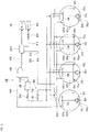
- FIG 3 is a diagram showing a schematic configuration of the fuel gas supply system 110 of the liquefied gas carrying vessel shown in FIG 2 .
- the tank 103 i has heat insulating properties that can maintain a cryogenic state so that LNG can be maintained in a liquid state at about - 162°C under atmospheric pressure
- a liquid phase portion 103a is on the lower side and a gas phase portion 103b is on the upper side, with a liquid surface of the stored LNG interposed therebetween, and the gas phase portion 103b contains gas containing NBOG
- the tank 103 i is provided with a liquid level meter (not shown) for detecting a liquid level of LNG in the tank 103 i .
- the LNG carrying vessel 100 has different ratios of the liquid phase portion 103a and the gas phase portion 103b in the tank 103 i , regarding the time of navigating from a gas production place to a gas consumption place (unloading place) (laden voyage), and the time of navigating from the gas consumption place to the gas production place (ballast voyage).
- the tank 103 i is filled with the liquefied gas.
- a state in which the liquid phase portion 103a of the LNG occupies about 98.5% or more of a tank capacity is regarded as "full load”.
- the LNG carrying vessel 100 navigates from the gas consumption place to the gas production place, a small amount of LNG is accommodated in the tank 103.
- a state in which the liquid phase portion 103a of the LNG is about 1.5% or less of the tank capacity is referred to as "empty load”.
- the ratio of the liquid phase portion 103a and the gas phase portion 103b fluctuates slightly as the LNG evaporates in the tank 103 i .
- the boil-off gas line 410 is constituted of at least one pipe connecting a gas inlet port 410a opening at an upper part of each tank 103 i and an inlet of the compressor 104.
- the NBOG in the tank 103 i is guided to the compressor 104 by the boil-off gas line 410.
- the boil-off gas lines 410 connected to the respective tanks 103 i are bundled together at a vapor gas header 410b, and on the downstream side of the vapor gas header 410b of the boil-off gas line 410, the LNG flowing out of each of the tanks 103 i joins and flows to the compressor 104.
- a pre-cooler that cools gas flowing into the compressor 104 a mist separator that removes moisture from the gas flowing into the compressor 104, and the like are provided downstream of the vapor gas header 410b of the boil-off gas line 410.
- the forced boil-off gas line 510 is provided with a pump 310 arranged in the liquid phase portion 103a in the tank 103, a boil-off device 520, and a forced boil-off valve 530 for controlling a flow rate of LNG flowing into the boil off device 520, and the above components are connected by piping or the like.
- the compressor 104 is a device that pressure-feeds the gas introduced from the upstream side to the downstream side. NBOG and/or FBOG taken into the compressor 104 is compressed and discharged to the fuel gas supply line 420. NBOG and/or FBOG thus compressed are used in the engine 102 as fuel gas.
- the compressor 104 according to the present embodiment is a low-duty compressor and is configured, for example, to intake gas at approximately atmospheric pressure, increase the pressure to about 500 kPa ( ⁇ 5 bar), which is a required pressure of the engine 102, and discharge the gas.
- the compressor 104 is, for example, an axial flow type or centrifugal type compressor, or the like, and is configured to vary an amount of discharge (or an amount of intake) by adjusting a degree of opening of a suction port and/or a rotation speed of a motor.
- the fuel gas supply line 420 includes at least one or more pipes connecting a discharge port of the compressor 104 and an inlet of the engine 102.
- the fuel gas supply line 420 is provided with a gas header 420a having a larger flow path cross-sectional area than other portions.
- the fuel gas supply line 420 branches off from the gas header 420a on the downstream side and the branched lines are connected to the plural engines 102.
- FIG 3 shows only one of the plural engines 102.
- a return line 610 for returning gas from the fuel gas supply line 420 to the tank 103 i is connected to the fuel gas supply line 420.
- An upstream end of the return line 610 according to the present embodiment is connected to the gas header 420a.
- the downstream end 630 of the return line 610 is located in the tank 103.
- the return line 610 is connected to each of the tanks 103 i , and is configured so that the fuel gas is returned from the fuel gas supply line 420 to each of the tanks 103.
- the return line 610 may be configured such that the gas returns to at least one of the plural tanks 103.
- the return line 610 is provided with a return valve 620 having a variable opening so that the flow path cross-sectional area of the return line 610 becomes variable.
- a degree of opening of the return valve 620 pressure of the gas header 420a is controlled so as to fall within an allowable range of the engine 102.
- an exhaust line 810 that guides gas to a gas combustion unit (GCU) 830 is connected to the fuel gas supply line 420.
- An upstream end of the exhaust line 810 according to the present embodiment is connected to the gas header 420a
- the gas combustion unit 830 combusts the gas guided from the fuel gas supply line 420 via the exhaust line 810 and exhausts the gas to the outside of the LNG carrying vessel 100.
- the exhaust line 810 is provided with an exhaust valve 820.
- the LNG carrying vessel 100 has a spray mechanism 700 that sucks out a part of LNG in the tank 103 i and sprays the LNG in the tank 103 i .
- the spray mechanism 700 includes the pump 310 arranged at the bottom of the tank 103 i , a collecting line 710 arranged outside the tank 103 i , a spray adjusting valve 720 for controlling a flow rate of LNG flowing into the collecting line 710, a spray line 730 extending into the tank 103 i , and a spray nozzle 740 provided at a tip of the spray line 730 inside the tank 103 i .
- piping between the pump 310 and the collecting line 710 is shared with the forced boil-off gas line 510. That is, the collecting line 710 is provided so as to branch off from the forced boil-off gas line 510.
- the spray mechanism 700 performs a spray operation of injecting the LNG stored in the tank 103 i into the tank 103 i via the pump 310, the collecting line 710, the spray line 730, and the spray nozzle 740.
- the spray nozzle 740 is configured so that plural nozzles having different degrees of opening can be switched from each other. Instead of this, a configuration may be made in which the degree of opening of one nozzle can be adjusted like in a variable valve, or plural nozzles are provided and opening portions of a part of the nozzles are blocked to allow the degree of opening to be adjusted.
- the spray limit index calculation unit 432 calculates a spray limit index indicating a change in liquid temperature of the LNG at the bottom of the tank caused by the spray operation of LNG (hereinafter, also referred to as a 0% position liquid temperature). That is, as shown in FIG 3 , when it is assumed that a virtual temperature measuring device 750 is provided at the bottom of the tank 103 i , a change in temperature measured by the temperature measuring device 750 is simulated.
- the temperature measuring device 750 may be actually provided at the bottom of the tank 103 i of the LNG carrying vessel 100, or a liquid thermometer normally installed at a 0% liquid level position may be used instead, to execute the simulation based on the measurement data.
- the unboiled off droplet comes into contact with the gas phase portion 103b in the tank 103 i , and the temperature of the droplet itself increases.
- the droplet sinks to the bottom of the tank 103 i because of its higher density than the heel originally stored in the tank 103 i , and the heel temporarily becomes two-layered by having an original liquid layer and a layer of heavy components formed by falling droplets.
- the 0% position liquid temperature becomes dominant to the unboiled off droplets that have fallen, and the 0% position liquid temperature increases more rapidly than before.
- the heavy component which becomes the droplets, continuously fall and accumulate at the bottom of the heel, so that the temperature continues to increase.
- FIG 4 because the temperature changes substantially linearly in each of the periods Nj and SPj, the change in temperature (inclination of the graph) in each of the periods Nj and SPj is substantially constant
- FIG 4 is merely an example, and a temporal change in the 0% position liquid temperature is not always a linear change. Therefore, it may be preferable to compare the change in temperature immediately after the spray operation is performed with the change in temperature immediately before the spray operation is performed.
- the simulation execution unit 431 changes the subsequent operation mode of the spray mechanism 700 and continues the simulation. For example, as in the present embodiment, when the spray mechanism 700 is configured to supply the LNG to be sprayed in each tank 103 i from one of at least two heel tanks 103 2 and 103 3 , and when the spray limit index SLI falls outside the range before arrival at the arrival place in the simulation, the simulation execution unit 431 may switch the heel tank being the supply source of the LNG to be sprayed in each tank 103 i to another heel tank and continue the simulation.
- the spray limit index SLI by calculating the spray limit index SLI based on the change in liquid temperature at the bottom of the tank before and after the spray operation is performed in the tank 103 i criteria for determining the degree of heaviness of heel and the cooling limit of the tank 103 i by the spray operation can be quantified.
- the case in which the change in temperature dT2/dt after the spray operation and the change in temperature dT1/dt before the spray operation are substantially equal is assessed to be the spray limit (spraying does not any longer contribute to cooling of the tank 103 i ). This makes it possible to easily perform the prediction calculation of the operation performed using LNG during the ballast voyage of the LNG carrying vessel 100.
- the change in the operation mode of the spray mechanism 700 is not limited to the above-described switching of the heel tank serving as the supply source.
- the simulation execution unit 431 may continue the simulation by changing the amount of spraying and/or interval of spraying in the spray mechanism 700.
- the simulation execution unit 431 may re-execute the simulation after the initial amount of heel is increased.
- the assumed LNG carrying vessel 100 has the premixed combustion gas engine 102 that can use the liquefied gas stored in the tank as fuel.
- the simulation execution unit 431 predicts and calculates a change in the amount of heel caused by supplying the engine 102 with fuel.
- composition ratios (R Wc1 , R Wc2 , R Wc3 , R Wc4 , R N2 ) of the boil-off gas in the sprayed droplets are obtained from the tank pressure P and the saturation temperature by calculating the thermophysical properties of the mixed composition.
- the methane number calculation unit 434 calculates the respective composition ratios R' Ghc1 , R' Ghc2 , R' Ghc3 , R' Ghc4 , and R' GhN2 after the spray operation by performing the above-described calculation. Further, the methane number calculation unit 434 calculates the methane number from the obtained composition ratios.
- the methane number calculation unit 434 calculates the methane number MN after the spray operation by performing the above-described calculation.
- the assessment unit 433 assesses whether or not the methane number of the heel and the boil-off gas falls outside a prescribed range. If the methane number MN falls outside the range, the assessment unit 433 assesses that the criteria is not met to supply the heel and the boil-off gas in the heel tanks 103 2 and 103 3 , serving as the supply source to the engine 102, to the premixed combustion gas engine.
- the simulation execution unit 431 changes a subsequent supply mode of LNG to the engine 102 and continues the simulation, or increases the amount of heel and re-executes the simulation.
- the change of the supply mode of LNG includes, for example, at least one of switching of the heel tanks 103 2 and 103 3 serving as the supply source, stopping of the LNG supply operation to the engine 102, and changing of the amount of LNG supply to the engine 102. Further, in addition to or instead of this, when the simulation is reexecuted by increasing the initial amount of heel, the simulation execution unit 431 executes the same processing as the effect assessment processing regarding the spray operation.
- the methane number of the heel and the boil-off gas can be calculated. This makes it possible to easily assess whether or not the LNG in the tank 103 i can be used as fuel for the premixed combustion gas engine.
- the assessment device 1 has been described in which both of the effect assessment processing related to the spray operation and the effect assessment processing related to the fuel supply operation can be executed.
- the present invention is not limited to this, and each of the effect assessment processing may be executed independently. That is, the assessment device 1 may be configured as a device that can execute only one of the effect assessment processing related to the spray operation and the effect assessment processing related to the fuel supply operation.
- the assessment device 1 that can execute the effect assessment processing related to the spray operation may not include the methane number calculation unit 434, and the assessment device 1 that can execute the effect assessment processing related to the fuel supply operation may not include the spray limit index calculation unit 432.
- the above-described mode can be executed not only before departure of the LNG carrying vessel 100, but also after departure of the LNG carrying vessel 100. In this case, the current position or future position (scheduled navigation position) of the LNG carrying vessel 100 becomes the departure place.
- the assessment device 1 is not limited to the mode of assessing the effect of the spray operation based on the prediction calculation of the spray operation. That is, in the above-described embodiment, the mode has been described in which the spray limit index calculation unit 432, the assessment unit 433, and the methane number calculation unit 434 are provided as functional blocks of the prediction calculation section 43 of the assessment device 1.
- the present invention is not limited to this.
- the spray limit index calculation unit 432, the assessment unit 433, and the methane number calculation unit 434 may be function blocks independent of the prediction calculation section 43. In this case, the assessment device 1 may not include the prediction calculation section 43 (simulation execution unit 431).
- the spray limit index SLI may be calculated based on the actual change in the 0% position liquid temperature. If the spray limit index SLI falls outside the prescribed range during the navigation, the assessment device 1 may output a prescribed output signal.
- This output signal may be a control signal input to a control device (not shown) of the LNG carrying vessel 100.
- the above control signal includes a control signal for switching the heel tank 103 i serving as the supply source to another heel tank 103 i , a control signal for stopping the subsequent spray operation, or the like.
- the assessment device 1 may calculate the methane number MN of the heel and the boil-off gas in the actual heel tanks 103 2 and 103 3 during the voyage of the LNG carrying vessel 100. For example, when the methane number MN falls outside the prescribed range during the navigation, a prescribed output signal may be output.
- This output signal may be a control signal input to a control device (not shown) of the LNG carrying vessel 100.
- the above control signal includes a control signal for switching the heel tank 103 i serving as the supply source to another heel tank 103 i a control signal for stopping the subsequent LNG supply operation to the engine 102 and switching the fuel to be supplied to the engine 102 to liquid fuel, or the like.
- the configuration has been exemplified in which the assessment device 1 includes the optimum route calculation section 42 that executes the optimum route calculation processing.
- the assessment device 1 may not include the optimum route calculation section 42.
- a configuration may be made in which a computer device mounted with plural applications such as a prediction calculation application and an optimum route calculation application executes each application, to thereby execute the optimum operation plan calculation as a whole.
- the LNG carrying vessel employing the propulsion system 900 of the DFD electric propulsion system is exemplified as the LNG carrying vessel 100 to be subjected to the operation effect assessment and the prediction calculation.
- the present invention is not limited thereto.
- the above-described operation effect assessment and/or prediction calculation can be executed for an LNG carrying vessel having a mechanical propulsion system in which the propulsion device is directly driven by the output of the engine 102.
- the mode has been described in which the operation mode of the spray mechanism is changed when the value of the spray limit index SLI falls outside the prescribed range. However, the above-described embodiment does not prevent the operation mode from being changed before the value falls outside the prescribed range.
- the mode has been described in which the supply mode of the liquefied gas to the premixed combustion gas engine is changed when the value of the methane number MN falls outside the prescribed range. However, the above-described embodiment does not prevent the supply mode from being changed before the methane number MN falls outside the prescribed range.
- the present invention is useful for providing an assessment device and an assessment method that can easily assess an effect of operation performed using liquefied gas during a ballast voyage of a liquefied gas carrying vessel.
Landscapes
- Engineering & Computer Science (AREA)
- Mechanical Engineering (AREA)
- Chemical & Material Sciences (AREA)
- Combustion & Propulsion (AREA)
- Ocean & Marine Engineering (AREA)
- Physics & Mathematics (AREA)
- General Engineering & Computer Science (AREA)
- Radar, Positioning & Navigation (AREA)
- Remote Sensing (AREA)
- Theoretical Computer Science (AREA)
- General Physics & Mathematics (AREA)
- Fluid Mechanics (AREA)
- Computer Hardware Design (AREA)
- Evolutionary Computation (AREA)
- Geometry (AREA)
- Automation & Control Theory (AREA)
- Filling Or Discharging Of Gas Storage Vessels (AREA)
- Traffic Control Systems (AREA)
- Navigation (AREA)
- Train Traffic Observation, Control, And Security (AREA)
Description
- The present invention relates to an assessment device and an assessment method of operation for a liquefied gas carrying vessel.
- A liquefied gas carrying vessel (liquefied natural gas (LNG) carrying vessel) needs to keep a tank temperature at or below a prescribed temperature during a ballast voyage after the LNG is transferred to the land (after unloading). Therefore, an operation of spraying LNG is performed to cool the tank. Further, the LNG in a tank and/or boil-oif gas obtained by boiling off the LNG are used as fuel for navigating the LNG carrying vessel. For this reason, it is necessary to keep a certain amount of LNG in the tank remained before the ballast voyage (at an unloading place). The LNG left in the tank in this way is called heel. It is necessary to set an amount of heel in the ballast voyage in consideration of an amount of LNG required for the spray operation and the fuel supply operation.
- Here, an optimum route calculation for vessels including the LNG carrying vessels has been given the most importance as effective means in operation management of the vessels, in view of reduction of operating costs caused by soaring fuel prices, reduction of greenhouse gas (GHG) emissions, and further, increasing needs for safe operation and maintaining and improving transport quality (for example, refer to
PTL 1 described below). In order to reduce the transportation cost and improve the transportation efficiency, it is desired that the LNG in the tank of the LNG carrying vessel be unloaded at the unloading place as much as possible to navigate the return route (ballast voyage) with the minimum amount of heel. Therefore, with the development of the above optimum route calculation method, when the accuracy of predicting the amount of LNG used in operations using the LNG increases, such as in the spray operation and the fuel supply operation, the amount of heel during the ballast voyage is expected to be set at the minimum necessary. - Patent Literature Document
JP2015 175488 - However, if the amount of heel is too small, a problem caused by deterioration of the stored LNG tends to become apparent. LNG is composed of plural components such as methane, ethane, propane, and butane, and each component has a different boiling point (saturation temperature). Therefore, when the LNG is sprayed in the tank to prevent the tank temperature from gradually rising, among the LNG being sprayed, methane being a component with the low saturation temperature boils off. However, ethane, propane, butane, or the like having a larger specific gravity and a higher saturation temperature than methane return to heel as a liquid without boiling off too much. For this reason, a component composition of the LNG remaining in the heel becomes heavier, and the saturation temperature of the entire heel gradually increases (heel becomes difficult to boil off).
- As a result, the temperature of heel gradually increases, and the temperature of the tank does not easily decrease even when the spraying is performed (reduction of spray cooling effect). In addition, as the heel becomes heavier, the ratio of ethane, propane, and butane in the boil-off gas generated by the spraying increases, causing knocking to occur more easily depending on the engine, and accordingly, the LNG and/or the boil-off gas obtained by boiling off the LNG cannot be used for the fuel.
- In formulating an operation plan for the LNG carrying vessel based on the optimum route calculation, the above-mentioned problem due to the LNG deterioration has not been considered so far, and it has been difficult to accurately predict various operations performed using LNG during the ballast voyage of the LNG carrying vessel.
- The present invention has been made in view of the above, and an object of the present invention is to provide an assessment device and an assessment method that can easily assess an effect of an operation performed using liquefied gas during a ballast voyage of a liquefied gas carrying vessel.
- According to one aspect of the present invention, the above object is achieved by an assessment device according to
claim 1. - According to the above configuration, by calculating the spray limit index based on the change in the liquid temperature at the bottom of the tank before and after the spray operation is performed in the tank, a degree of heaviness of heel is predicted. This makes it possible to easily assess the effect of the operation performed using the liquefied gas during the ballast voyage of the liquefied gas carrying vessel.
- The assessment device may include a simulation execution unit that executes, using an initial amount of heel indicating an amount of the liquefied gas stored in the tank at a departure place of the ballast voyage, a simulation of the spray operation using the spray mechanism in a route from the departure place to an arrival place of the ballast voyage. Further, when the spray limit index falls outside the range before arrival at the arrival place in the simulation, the simulation execution unit may be configured to continue the simulation after changing a subsequent operation mode of the spray mechanism. With this configuration, the effectiveness of the spray operation can be determined.
- The assessment device may include a simulation execution unit that executes, using an initial amount of heel indicating the amount of the liquefied gas stored in the tank at a departure place of the ballast voyage, a simulation of the spray operation using the spray mechanism in a route from the departure place to an arrival place of the ballast voyage. Further, when the spray limit index falls outside the range before arrival at the arrival place in the simulation, the simulation execution unit may be configured to increase the initial amount of heel and re-execute the simulation. With this configuration, it is possible to determine in advance whether the initial amount of heel is the minimum (optimum).
- The spray limit index calculation unit calculates, as the spray limit index, a difference between an amount of change in liquid temperature per unit time of the liquefied gas before the spray operation of the liquefied gas and an amount of change in liquid temperature per unit time of the liquefied gas after the spray operation of the liquefied gas. By calculating and comparing the amount of change in liquid temperature per unit time at the bottom of the tank before and after the spraying is performed in the tank, it is possible to appropriately predict the degree of heaviness of heel.
- The liquefied gas carrying vessel may include plural tanks, and at least one of the plural tanks may be a non-heel tank that stores only a minimum required amount of the liquefied gas during the ballast voyage. Further, the spray limit index calculation unit may calculate the spray limit index based on a liquid temperature of the liquefied gas at a bottom of the non-heel tank. By simulating the change in temperature in the non-heel tank in which the amount of heel stored in the tank is small from the beginning, it is possible to detect with high accuracy the change in liquid temperature caused by the heel becoming heavy.
- The liquefied gas carrying vessel may include plural tanks, and at least two of the plural tanks may be heel tanks that store the liquefied gas used for navigation of the liquefied gas carrying vessel in the ballast voyage. Further, the spray mechanism may be configured to supply liquefied gas being sprayed in each tank from at least one of the at least two heel tanks, and when the spray limit index falls outside the range, the assessment device may switch the heel tank as a supply source of liquefied gas to be sprayed in each tank to another heel tank. Thus, when the plural tanks are set as the heel tanks, the supply source of the liquefied gas can be switched at an optimum timing.
- The assessment device may stop the spray operation performed subsequently when the spray limit index falls outside the range. Thus, it is possible to prevent the spray operation by which the effect cannot be expected from continuing.
- The liquefied gas carrying vessel may include a premixed combustion gas engine that can use the liquefied gas stored in the tank as fuel. Further, the assessment device may include a methane number calculation unit that calculates a composition change of the liquefied gas stored in the tank and a boil-off gas in the tank after the spray operation of the liquefied gas is performed using the spray mechanism, and calculates a methane number of the liquefied gas and the boil-off gas. Still further, the assessment unit may be configured to assess whether or not the methane number of the liquefied gas after the spray operation of the liquefied gas is performed falls outside a prescribed range.
- According to the above configuration, an amount of composition change of the boil-off gas and the liquefied gas (heel) stored in the tank after the spray operation is performed is calculated, and the methane number of the boil-off gas and the heel is calculated, whereby the degrees of heaviness of the boil-off gas and the heel are predicted. Therefore, it can be easily assessed whether or not the liquefied gas in the tank can be used as the fuel for the premixed combustion gas engine. Therefore, the effectiveness of the fuel supply operation can be determined in addition to the effectiveness of the spray operation.
- The assessment device may include a simulation execution unit that executes, using an initial amount of heel indicating an amount of the liquefied gas stored in the tank at a departure place of the ballast voyage, a simulation of the spray operation using the spray mechanism in a route from the departure place to an arrival place of the ballast voyage. Further, when the methane number falls outside the range before arrival at the arrival place in the simulation, the simulation execution unit may be configured to continue the simulation after changing a subsequent supply mode of the liquefied gas to the premixed combustion gas engine. With this configuration, the effectiveness of the fuel supply operation can be determined in advance in addition to the effectiveness of the spray operation.
- The assessment device may include a simulation execution unit that executes, using an initial amount of heel indicating an amount of the liquefied gas stored in the tank at a departure place of the ballast voyage, a simulation of the spray operation using the spray mechanism in a route from the departure place to an arrival place of the ballast voyage. Further, when the methane number falls outside the range before arrival at the arrival place in the simulation, the simulation execution unit may be configured to increase the initial amount of heel and re-execute the simulation. With this configuration, it can be determined whether the initial amount of heel is the minimum (optimum).
- According to another aspect of the present invention, an assessment method according to claim 10 is provided.
- According to the above method, by calculating the spray limit index based on the change in the liquid temperature at the bottom of the tank before and after the spray operation is performed in the tank, a degree of heaviness of heel is predicted. This makes it possible to easily assess the effect of the operation performed using the liquefied gas during the ballast voyage of the liquefied gas carrying vessel.
- According to the present invention, it is possible of easily assess the effect of an operation performed using the liquefied gas during the ballast voyage of the liquefied gas carrying vessel.
-
-
FIG 1 is a block diagram showing a schematic configuration of an assessment device according to one embodiment of the present invention. -
FIG 2 is a schematic configuration diagram showing an example of a propulsion system of a liquefied gas carrying vessel being a target of the assessment device shown inFIG 1 . -
FIG. 3 is a diagram showing a schematic configuration of a fuel gas supply system of the liquefied gas carrying vessel shown inFIG 2 . -
FIG 4 is a graph showing a temporal change in a 0% position liquid temperature of a non-heel tank. - Hereinafter, an embodiment of the present invention is described in detail with reference to the drawings. In the following, the same or corresponding elements are denoted by the same reference symbols throughout all the drawings, and redundant descriptions are omitted.
-
FIG 1 is a block diagram showing a schematic configuration of an assessment device according to one embodiment of the present invention. Theassessment device 1 shown inFIG 1 includes aninput portion 2, astorage portion 3, acalculation portion 4, and anoutput portion 5. Each of thecomponents 2 to 5 of theassessment device 1 mutually transmit data via abus 6. Theassessment device 1 may be configured with a computer in a ground facility, or may be configured as a computer or a control device installed on a liquefied gas carrying vessel (LNG carrying vessel). In addition, a configuration may be made in which some of the functions that constitute theassessment device 1 are exerted by a computer installed on the LNG carrying vessel, and other functions are exerted by a computer installed on the ground, and data is mutually communicated using communicators such as a ship-to-ground communication. - The
input portion 2 is configured as an input device that allows a user to input information such as a departure place, an arrival place, a departure time, and an arrival time of the LNG carrying vessel. Furthermore, the information input from theinput portion 2 includes an amount of heel of liquefied gas (LNG) stored in a tank of the LNG carrying vessel (initial amount of heel), an LNG composition (initial composition), an LNG liquid temperature (initial liquid temperature), and a tank pressure (initial tank pressure), and the like, at the departure place of a ballast voyage (unloading place of LNG). Thestorage portion 3 stores information input from theinput portion 2. Thestorage portion 3 stores, in advance, performance data of the LNG carrying vessel, weather data of at least a route area where the LNG carrying vessel navigates, and various calculation programs such as a prediction calculation program and an optimum route calculation program, which are described later. - The performance data of the LNG carrying vessel is data on the performance that each LNG carrying vessel has individually. The weather data is provided from, for example, an external organization. The weather data is, for example, data on weather (sea weather) in the route area or the like one week ahead of the present time. Note that a configuration may be made in which the weather data is sequentially transmitted from the outside through a network, and is automatically stored in the
storage portion 3. - The
calculation portion 4 executes optimum operation plan calculation processing for calculating an optimum route of the LNG carrying vessel and an optimum operation plan including various operation controls on the route based on the various pieces of information stored in thestorage portion 3. The optimum operation plan is created by adding a concept of time (preferred values such as departure time, arrival time, time at a prescribed position on the route, and stop time at a prescribed position on the route) to the optimum route, and including the execution necessity of various operations at each time. - To this end, the
calculation portion 4 exerts the functions of an informationinput reception section 41, an optimumroute calculation section 42, aprediction calculation section 43, and the like by appropriately executing the optimum route calculation program, the prediction calculation program, and the like. - The information
input reception section 41 receives input of information including the departure place, the arrival place, the departure time, the arrival time, the initial amount of heel, the initial composition, the initial liquid temperature, the initial tank pressure, and the like of theLNG carrying vessel 100. The optimumroute calculation section 42 calculates the optimum route based on the input information, the performance data of the vessel stored in thestorage portion 3, and the weather data of the route area where the vessel travels. The optimumroute calculation section 42 can execute an optimum route calculation by, for example, the dynamic programming (DP) method, the calculus of variations, the Dijkstra method, the A-star method, or the isochronous curve method. The optimumroute calculation section 42 calculates as an optimum route, for example, a route that minimizes an evaluation function of parameters related to navigation safety such as wave height and hull vibration based on the weather data and fuel efficiency based on the performance data of the vessel. - The
prediction calculation section 43 executes an execution prediction calculation of an operation performed using LNG during the ballast voyage of the LNG canying vessel. For this reason, theprediction calculation section 43 exerts the functions of asimulation execution unit 431, a spray limitindex calculation unit 432, anassessment unit 433, a methanenumber calculation unit 434, and the like. The details are described later. - The
output portion 5 outputs a calculation result of thecalculation portion 4. For example, theoutput portion 5 displays the optimum operation plan calculated by thecalculation portion 4 on a map (nautical chart) on a display device (not shown) connected to theassessment device 1. Further, theoutput portion 5 may display, on the map, a point where spray control is executed, and may display a list of temperature changes before and after the execution of the control. - Hereinafter, a configuration of the LNG carrying vessel to be subjected to effect assessment processing in the present embodiment is described.
FIG 2 is a schematic configuration diagram showing an example of apropulsion system 900 of the liquefied gas carrying vessel (LNG carrying vessel) 100 being a target of the assessment device shown inFIG 1 . TheLNG carrying vessel 100 shown inFIG 2 employs a dual-fuel diesel (DFD) electric propulsion system as thepropulsion system 900. - The
propulsion system 900 of theLNG carrying vessel 100 includes apower generation unit 910, apropulsion unit 930 driven by the power generated by thepower generation unit 910, and a power distribution andcontrol unit 920 provided in a power supply system from thepower generation unit 910 to thepropulsion unit 930. Thepower generation unit 910 includes plural sets of apower generation engine 102 and apower generator 912, and the like. Mechanical energy generated by theengine 102 is extracted as electric power by thepower generator 912. - The
propulsion unit 930 includes at least onepropulsion motor 931, apropulsion device 933 driven by the output of thepropulsion motor 931, areduction gear 932 provided on a power transmission path from thepropulsion motor 931 to thepropulsion device 933, and the like. The power distribution andcontrol unit 920 includes apower distribution panel 921 for distributing electric power from thepower generation unit 910, aninverter 922 for controlling the output (i.e., rotation speed) of thepropulsion motor 931, and the like. However, the thrust may be adjusted by setting a rotation speed of thepropulsion motor 931 to be constant and changing a pitch using a variable pitch propeller. - The rotation speed of the
propulsion motor 931 is determined, for example, by an amount of operation of a maneuvering device such as a not-shown telegraph lever, and power equivalent to a required power value corresponding to the rotation speed is supplied from the power distribution andcontrol unit 920 to thepropulsion unit 930. In this way, an amount of fuel corresponding to an amount of power generation is supplied to thepower generation unit 910 so that the power generated by thepower generation unit 910 is sufficient for the power used by auxiliary equipment, onboard equipment, and the like, in addition to the power used by thepropulsion unit 930. - In the
propulsion system 900 having the above configuration, theengine 102 is a dual-fuel four-cycle diesel engine that can bum oil and gas. Therefore, the fuel supply system to theengine 102 includes a fuel gas (premixed combustion gas)supply system 960 for supplying fuel gas to theengine 102, and a fueloil supply system 970 for supplying fuel oil such as heavy oil stored in afuel oil tank 950 to theengine 102. InFIG 2 , the fuelgas supply system 960 is indicated by a dashed arrow, and the fueloil supply system 970 is indicated by a solid arrow. The fuelgas supply system 960 is constituted of a fuelgas supply system 110 that supplies, to theengine 102, gas produced by having the liquefied gas in a liquefiedgas transport tank 103 naturally boiled off (hereinafter, referred to as "NBOG"), and/or forced boil-off gas produced by having the liquefied gas in thetank 103 forcibly boiled off (hereinafter, referred to as "FBOG"). Hereinafter, the fuelgas supply system 110 is described in detail. -
FIG 3 is a diagram showing a schematic configuration of the fuelgas supply system 110 of the liquefied gas carrying vessel shown inFIG 2 . TheLNG carrying vessel 100 is provided with the plurallarge tanks 103 arranged in a vessel length direction, and the fourtanks 103 are shown inFIG 3 . Therefore, inFIG 3 and the following description, each of the plural tanks is referred to as the tank 103i (i = 1, 2, 3, 4). Thetank 103i has heat insulating properties that can maintain a cryogenic state so that LNG can be maintained in a liquid state at about - 162°C under atmospheric pressure - The fuel
gas supply system 110 shown inFIG 3 includes the tanks 103i (i = 1, 2, 3, 4) storing the liquefied gas, acompressor 104 having a variable amount of discharge, boil-offgas lines 410 that guide NBOG generated in thetanks 103i to thecompressor 104, and a fuelgas supply line 420 that guides to theengine 102 the fuel gas (premixed combustion gas) in which gas containing NBOG is compressed by thecompressor 104. - In the
tank 103i, aliquid phase portion 103a is on the lower side and agas phase portion 103b is on the upper side, with a liquid surface of the stored LNG interposed therebetween, and thegas phase portion 103b contains gas containing NBOG Thetank 103i is provided with a liquid level meter (not shown) for detecting a liquid level of LNG in thetank 103i. - In general, the
LNG carrying vessel 100 has different ratios of theliquid phase portion 103a and thegas phase portion 103b in thetank 103i, regarding the time of navigating from a gas production place to a gas consumption place (unloading place) (laden voyage), and the time of navigating from the gas consumption place to the gas production place (ballast voyage). For example, when theLNG canying vessel 100 travels from the gas production place to the gas consumption place, thetank 103i is filled with the liquefied gas. For example, a state in which theliquid phase portion 103a of the LNG occupies about 98.5% or more of a tank capacity is regarded as "full load". When theLNG carrying vessel 100 navigates from the gas consumption place to the gas production place, a small amount of LNG is accommodated in thetank 103. For example, a state in which theliquid phase portion 103a of the LNG is about 1.5% or less of the tank capacity is referred to as "empty load". During the navigation of theLNG carrying vessel 100, the ratio of theliquid phase portion 103a and thegas phase portion 103b fluctuates slightly as the LNG evaporates in thetank 103i. - The boil-off
gas line 410 is constituted of at least one pipe connecting agas inlet port 410a opening at an upper part of eachtank 103i and an inlet of thecompressor 104. The NBOG in thetank 103i is guided to thecompressor 104 by the boil-offgas line 410. In the present embodiment, the boil-offgas lines 410 connected to therespective tanks 103i are bundled together at avapor gas header 410b, and on the downstream side of thevapor gas header 410b of the boil-offgas line 410, the LNG flowing out of each of thetanks 103i joins and flows to thecompressor 104. Although not shown, a pre-cooler that cools gas flowing into thecompressor 104, a mist separator that removes moisture from the gas flowing into thecompressor 104, and the like are provided downstream of thevapor gas header 410b of the boil-offgas line 410. - To the boil-off
gas line 410, there is connected the downstream end of a forced boil-offgas line 510 that guides the LNG in thetank 103 to thecompressor 104. The forced boil-offgas line 510 is provided with apump 310 arranged in theliquid phase portion 103a in thetank 103, a boil-offdevice 520, and a forced boil-offvalve 530 for controlling a flow rate of LNG flowing into the boil offdevice 520, and the above components are connected by piping or the like. In the forced boil-offgas line 510, the LNG in thetank 103i is pumped to the boil-offdevice 520 by the operation of thepump 310, and FBOG in which the LNG is forcibly boiled off by the boil offdevice 520 is sent to thecompressor 104. - The
compressor 104 is a device that pressure-feeds the gas introduced from the upstream side to the downstream side. NBOG and/or FBOG taken into thecompressor 104 is compressed and discharged to the fuelgas supply line 420. NBOG and/or FBOG thus compressed are used in theengine 102 as fuel gas. Thecompressor 104 according to the present embodiment is a low-duty compressor and is configured, for example, to intake gas at approximately atmospheric pressure, increase the pressure to about 500 kPa (≈ 5 bar), which is a required pressure of theengine 102, and discharge the gas. Thecompressor 104 according to the present embodiment is, for example, an axial flow type or centrifugal type compressor, or the like, and is configured to vary an amount of discharge (or an amount of intake) by adjusting a degree of opening of a suction port and/or a rotation speed of a motor. - The fuel
gas supply line 420 includes at least one or more pipes connecting a discharge port of thecompressor 104 and an inlet of theengine 102. The fuelgas supply line 420 is provided with agas header 420a having a larger flow path cross-sectional area than other portions. The fuelgas supply line 420 branches off from thegas header 420a on the downstream side and the branched lines are connected to theplural engines 102.FIG 3 shows only one of theplural engines 102. - A
return line 610 for returning gas from the fuelgas supply line 420 to thetank 103i is connected to the fuelgas supply line 420. An upstream end of thereturn line 610 according to the present embodiment is connected to thegas header 420a. Thedownstream end 630 of thereturn line 610 is located in thetank 103. In the present embodiment, thereturn line 610 is connected to each of thetanks 103i, and is configured so that the fuel gas is returned from the fuelgas supply line 420 to each of thetanks 103. However, thereturn line 610 may be configured such that the gas returns to at least one of theplural tanks 103. - The
return line 610 is provided with areturn valve 620 having a variable opening so that the flow path cross-sectional area of thereturn line 610 becomes variable. By controlling a degree of opening of thereturn valve 620, pressure of thegas header 420a is controlled so as to fall within an allowable range of theengine 102. - Further, an
exhaust line 810 that guides gas to a gas combustion unit (GCU) 830 is connected to the fuelgas supply line 420. An upstream end of theexhaust line 810 according to the present embodiment is connected to thegas header 420a Thegas combustion unit 830 combusts the gas guided from the fuelgas supply line 420 via theexhaust line 810 and exhausts the gas to the outside of theLNG carrying vessel 100. Theexhaust line 810 is provided with anexhaust valve 820. - Further, the
LNG carrying vessel 100 has aspray mechanism 700 that sucks out a part of LNG in thetank 103i and sprays the LNG in thetank 103i. Thespray mechanism 700 includes thepump 310 arranged at the bottom of thetank 103i, acollecting line 710 arranged outside thetank 103i, aspray adjusting valve 720 for controlling a flow rate of LNG flowing into the collectingline 710, aspray line 730 extending into thetank 103i, and aspray nozzle 740 provided at a tip of thespray line 730 inside thetank 103i. - In the present embodiment, piping between the
pump 310 and thecollecting line 710 is shared with the forced boil-offgas line 510. That is, the collectingline 710 is provided so as to branch off from the forced boil-offgas line 510. Thespray mechanism 700 performs a spray operation of injecting the LNG stored in thetank 103i into thetank 103i via thepump 310, the collectingline 710, thespray line 730, and thespray nozzle 740. - The
spray nozzle 740 is configured so that plural nozzles having different degrees of opening can be switched from each other. Instead of this, a configuration may be made in which the degree of opening of one nozzle can be adjusted like in a variable valve, or plural nozzles are provided and opening portions of a part of the nozzles are blocked to allow the degree of opening to be adjusted. - The spray operation is performed during the ballast voyage when the
liquid phase portion 103a of LNG is low. During the ballast voyage, the amount of LNG (liquid phase portion 103a, or heel) stored in thetank 103i is small. Therefore, the temperature of thetank 103i and the gas temperature in thetank 103i increase due to heat entering from outside thetank 103i. The spray operation is performed to prevent or suppress this. For this reason, for example, the spray operation is performed when an equatorial temperature of the tank 103i (temperature at the center in the height direction of the tank 103i) is a prescribed temperature or higher (for example, -110°C, that is, for example, +50°C of the temperature of theliquid phase portion 103a). - Among the
plural pumps 310, onepump 310 operates in the spray operation. That is, onetank 103i of the plural tanks 103i (for example, 1032) serves as a supply source of LNG for the spray operation. For example, in theLNG carrying vessel 100, at least one of theplural tanks 103i is a non-heel tank in which only the minimum amount of LNG is stored during the ballast voyage. In the example ofFIG 3 , twotanks tanks 103i are set as non-heel tanks. Thenon-heel tanks pump 310 has remained as a result in the tank at the unloading place. - On the other hand, the remaining
tanks LNG carrying vessel 100 and the spray operation, and these tanks are hereinafter referred to as heel tanks. Theheel tanks - An amount of spraying in the spray operation is adjusted by adjusting the power supplied to the
pump 310 and the degree of opening of a valve (not shown) set downstream of thepump 310 to adjust the pump output, by adjusting the time of ejecting the LNG from thespray nozzle 740, and/or by adjusting the degree of opening of thespray nozzle 740. - As described above, the spray operation is performed to prevent or suppress the increase in temperature of the
tank 103i and gas temperature in thetank 103i. The boil-off gas generated by the spray operation is consumed by being supplied to theengine 102 as fuel. However, when a tank pressure exceeds an allowable pressure in a state of the consumption of boil-off gas in theengine 102 being small and the amount of boil-off gas generated by the spray operation being large, the excess boil-off gas is sent from thetank 103i to thegas combustion unit 830. Then, the excess boil-off gas is burned and exhausted in thegas combustion unit 830. Thus, the excess boil-off gas is wasted. Further, there is a limit to the amount of boil-off gas to be treated in thegas combustion unit 830. Therefore, the spray operation needs to be optimized so as not to emit excess boil-off gas. - As described above, during the ballast voyage of the
LNG carrying vessel 100, the LNG is used in performing the spray operation and the fuel supply operation for supplying fuel to theengine 102. It is necessary to set an amount of heel in the ballast voyage in consideration of an amount of LNG required for the spray operation and the fuel supply operation. Theprediction calculation section 43 of theassessment device 1 executes a prediction calculation of the above operations during the ballast voyage of theLNG carrying vessel 100. In addition, theassessment device 1 assesses the effect of the above operations based on a result of the prediction calculation of the operations. - First, the effect assessment processing regarding the spray operation is described. First, the
prediction calculation section 43 predicts a temperature change in thetank 103i from the optimum route calculated by the optimumroute calculation section 42 and weather data on the optimum route. Then, thesimulation execution unit 431 simulates the spray operation of thespray mechanism 700 on the route from the departure place to the arrival place of the ballast voyage using an initial amount of heel that is input. At this time, thesimulation execution unit 431 executes prediction calculation on an amount of spraying in a case of performing the spray operation according to a change in temperature of thetank 103i and a change in gas temperature in thetank 103i, on a change in temperature of thetank 103i and a change in gas temperature in thetank 103i by the spray operation (suppression effect), a state of heel used for spraying, and the like. - In order to predict the change in state of the heel according to the spray operation in the simulation, the spray limit
index calculation unit 432 calculates a spray limit index indicating a change in liquid temperature of the LNG at the bottom of the tank caused by the spray operation of LNG (hereinafter, also referred to as a 0% position liquid temperature). That is, as shown inFIG 3 , when it is assumed that a virtualtemperature measuring device 750 is provided at the bottom of thetank 103i, a change in temperature measured by thetemperature measuring device 750 is simulated. - In addition, the
temperature measuring device 750 may be actually provided at the bottom of thetank 103i of theLNG carrying vessel 100, or a liquid thermometer normally installed at a 0% liquid level position may be used instead, to execute the simulation based on the measurement data. - In the present embodiment, the spray limit
index calculation unit 432 calculates the spray limit index based on the liquid temperature of LNG at the bottom of thenon-heel tanks index calculation unit 432 calculates a difference between dT1/dt, which is an amount of change in liquid temperature (0% position liquid temperature) of LNG per unit time before the spray operation of LNG and dT2/dt, which is an amount of change in liquid temperature (0% position liquid temperature) of LNG per unit time after the spray operation of LNG, as the spray limit index SLI (= dT2/dt - dT1/dt). - The meaning of the spray limit index SLI is described in detail.
FIG 4 is a graph showing a temporal change in liquid temperature at the 0% position liquid temperature of the non-heel tank. A position where a time axis being the horizontal axis is 0 corresponds to the departure time of the ballast voyage. In the ballast voyage, the equatorial temperature of thetank 103i increases while the 0% position liquid temperature gradually increases after the navigation is started from the departure place and before the spray operation is performed (period N1). When the equatorial temperature becomes a prescribed temperature or higher, the spray operation is performed. At this time, the heel LNG stored in the heel tank (for example, tank 1032) is sucked up by thepump 310 and sprayed from eachspray nozzle 740 of eachtank 103i. - In the spray operation, among the components of LNQ methane (saturation temperature of -161.5°C, density of 0.656 kg/m3 at normal pressure) having a low specific gravity mainly boils off However, the remaining components having a large specific gravity such as ethane (saturation temperature of -89°C, density of 1.36 kg/m3 at normal pressure), propane (saturation temperature of -42°C, density of 2.01 kg/m3 at normal pressure), butane (saturation temperature of -1°C, density of 2.48 kg/m3 at normal pressure), hardly boil off because the saturation temperature is high, and fall into the heel of the
tank 103i while remaining as droplets. - When the remaining components fall, the unboiled off droplet comes into contact with the
gas phase portion 103b in thetank 103i, and the temperature of the droplet itself increases. When the unboiled off droplet falls into the heel in this state, the droplet sinks to the bottom of thetank 103i because of its higher density than the heel originally stored in thetank 103i, and the heel temporarily becomes two-layered by having an original liquid layer and a layer of heavy components formed by falling droplets. As a result, the 0% position liquid temperature becomes dominant to the unboiled off droplets that have fallen, and the 0% position liquid temperature increases more rapidly than before. During the spray operation (period SP1), the heavy component, which becomes the droplets, continuously fall and accumulate at the bottom of the heel, so that the temperature continues to increase. - When the spray operation is completed, the heated droplets do not fall any longer, and accordingly, the 0% position liquid temperature does not rapidly increase any longer. Then, because the two-layered heel is mixed by convection, the heel becomes single-layered.
- After the end of the spray operation, the 0% position liquid temperature increases gradually as in the case before the spray operation (period N2). By repeating the spray operation (by repeating the period Nj (j = 1,2,...) and the period SPj alternately), the equatorial temperature of the
tank 103i is maintained at a prescribed temperature or below, or the temperature gradually decreases toward the prescribed temperature. However, while the 0% position liquid temperature of thenon-heel tank - However, when the spray operation is repeated, the liquid temperature of the entire heel increases, and when the spray operation is performed, a difference between the liquid temperature of the heel sprayed from the
spray nozzle 740, and the equatorial temperature of thetank 103i and the temperature of thegas phase portion 103b becomes smaller. As a result, even when the unboiled off droplets come into contact with thegas phase portion 103b in thetank 103i by the spray operation, the temperature increase becomes small. Further, because the temperature of the heel itself also increases, the rapid temperature increase no longer occurs even when the droplets fall into the heel. InFIG. 4 , the angle θj formed by an inclination of a graph in the period Nj and an inclination of the graph in the period SPj decreases with time (as j increases). - Therefore, by predicting the change of the 0% position liquid temperature before and after the spray operation by the spray limit index SLI as described above, it is possible to predict the heel stored in the
heel tanks FIG. 4 ) in the period SPj of each spray operation is compared with dT1/dt, which is the change in temperature (inclination in the graph ofFIG 4 ) in the period Nj before performing each spray operation - In
FIG 4 , because the temperature changes substantially linearly in each of the periods Nj and SPj, the change in temperature (inclination of the graph) in each of the periods Nj and SPj is substantially constant However,FIG 4 is merely an example, and a temporal change in the 0% position liquid temperature is not always a linear change. Therefore, it may be preferable to compare the change in temperature immediately after the spray operation is performed with the change in temperature immediately before the spray operation is performed. - The
assessment unit 433 assesses whether or not the spray limit index SLI falls outside a prescribed range. In the present embodiment, when SLI = dT2/dt - dT1/dt < a, theassessment unit 433 assesses that the spray limit index SLI falls outside the prescribed range. A threshold value α is set to, for example, 0 or a value close to 0. When the spray limit index SLI falls outside the range before arrival at the arrival place in the simulation, theassessment unit 433 assesses that the cooling effect of the tank by the spray operation of the spray mechanism is at the limit. - When the spray limit index SLI falls outside the range before arrival at the arrival place in the simulation, the
simulation execution unit 431 changes the subsequent operation mode of thespray mechanism 700 and continues the simulation. For example, as in the present embodiment, when thespray mechanism 700 is configured to supply the LNG to be sprayed in eachtank 103i from one of at least twoheel tanks simulation execution unit 431 may switch the heel tank being the supply source of the LNG to be sprayed in eachtank 103i to another heel tank and continue the simulation. - For example, when the
heel tank 1032 is initially used as the supply source of LNG to be sprayed, when the spray limit index SLI falls outside the range, the liquid temperature (0% position liquid temperature) of anotherheel tank 1033 is obtained, and when the liquid temperature thereof is lower than that of theheel tank 1032 serving as the current supply source, the heel tank used as the supply source of LNG may be switched from thetank 1032 to thetank 1033. - When there are plural heel tanks, and when the spray limit index SLI in the
heel tank 1032 serving as the supply source of the spray operation falls outside the range, the supply source of LNG for the spray operation is switched to anotherheel tank 1033. With this, the spray operation is continued. - According to the above configuration, by calculating the spray limit index SLI based on the change in liquid temperature at the bottom of the tank before and after the spray operation is performed in the
tank 103i criteria for determining the degree of heaviness of heel and the cooling limit of thetank 103i by the spray operation can be quantified. In the present embodiment, the case in which the change in temperature dT2/dt after the spray operation and the change in temperature dT1/dt before the spray operation are substantially equal is assessed to be the spray limit (spraying does not any longer contribute to cooling of the tank 103i). This makes it possible to easily perform the prediction calculation of the operation performed using LNG during the ballast voyage of theLNG carrying vessel 100. - Note that the change in the operation mode of the
spray mechanism 700 is not limited to the above-described switching of the heel tank serving as the supply source. For example, thesimulation execution unit 431 may continue the simulation by changing the amount of spraying and/or interval of spraying in thespray mechanism 700. - Further, when the spray limit index SLI falls outside the range before arrival at the arrival place in the simulation, the
simulation execution unit 431 may re-execute the simulation after the initial amount of heel is increased. - Further, the change of the operation mode and the change of the initial amount of heel may be combined. For example, the
assessment device 1 may first perform the simulation by setting theheel tank 1032 as the supply source of LNG to be sprayed, and when the spray limit index SLI falls outside the range, the simulation may be continued after the supply source of LNG is switched from theheel tank 1032 to theheel tank 1033, and when the spray limit index SLI falls outside the range again, the simulation may be performed again after the initial amount of heel is increased. - The initial amount of heel may be increased by an amount calculated by the simulation, or by a prescribed amount When the prescribed amount is set, the
simulation execution unit 431 increases the initial amount of heel by the prescribed amount each time the spray limit index SLI falls outside the range in the simulation, and repeats the simulation. For example, the minimum initial amount of heel in the case when the simulation ends with the spray limit index SLI remaining within the range until the arrival place of the ballast voyage, is output from theoutput portion 5 as the initial amount of heel necessary for the spray operation of the ballast voyage. - Next, the effect assessment processing regarding the fuel supply operation is described. As described above, in the present embodiment, the assumed
LNG carrying vessel 100 has the premixedcombustion gas engine 102 that can use the liquefied gas stored in the tank as fuel. Thesimulation execution unit 431 predicts and calculates a change in the amount of heel caused by supplying theengine 102 with fuel. - Then, the methane
number calculation unit 434 calculates the change in composition of the boil-off gas in thetank 103i and the LNG stored in thetank 103i after the spraying of the LNG by thespray mechanism 700, and calculates a methane number of the LNG In the present embodiment, the methanenumber calculation unit 434 calculates the change in composition of the boil-off gas in theheel tanks heel tanks engine 102, and calculates the methane number of the boil-off gas and the LNG - First, a mode of calculating the change in composition of boil-off gas and LNG is described. In the mixed composition of LNG, it is assumed that methane is C1, ethane is C2, propane is C3, butane is C4, and nitrogen is N2. Further, it is assumed that a weight of heel stored in the
tank 103i is Gheel, a heel liquid temperature is T, and a tank pressure is P. Heel composition ratios (RGhc1, RGhc2, RGhc3, RGhc4, RGhN2) at this time are assumed to be known. In the following, the calculation is performed assuming that the LNG is composed of five types of compositions. However, the same calculation can be performed even when some of these components are not included or when other components are included. - Among the droplets sucked by the
pump 310 from theheel tanks spray nozzle 740 into thetank 103i, assuming that a weight of the droplets that boil off and become the boil-off gas is Gsg and a weight of the droplets that remain without boiling off is Gsl, a mass fraction (quality) x of the sprayed droplet is represented by x = Gsg/(Gsg + Gs1). The quality x is obtained from the tank pressure P and the saturation temperature by calculating the thermophysical properties of the mixed composition. Assuming that the total weight of the sprayed droplets is Gspray (Gspay = Gsg + Gsl), a boil-off amount W of the sprayed droplets is obtained as W=x×Gspray. - The composition ratios (RWc1, RWc2, RWc3, RWc4, RN2) of the boil-off gas in the sprayed droplets are obtained from the tank pressure P and the saturation temperature by calculating the thermophysical properties of the mixed composition.
- From the boil-off amount w and the composition ratios of the boil-off gas (RWc1, RWc2, Rwc3, RWc4, RN2), the boil-off amounts of respective compositions of the boil-off gas (Wc1), Wc2, Wc3, Wc4, WN2) are obtained as Wc1 = W × RWc1, Wc2 = W × RWc2, Wc3 = W × RWc3, Wc4 = W × RWc4, WN2 = W × RWN2, respectively. Therefore, the amount of each of the compositions (Grc1, Grc2, Grc3, Grc4, GrN2) of the droplets that could not completely boil off among the sprayed droplets is obtained by subtracting the boil-off amount of each composition from the amount of each composition of the sprayed droplets. That is, the amounts of respective compositions of the sprayed droplets (Gsc1, Gsc2, Gsc3, Gsc4, GsN2) are Gsc1 = Gspray × RGhc1, Gsc2 = Gspray × RGhc2, Gsc3 = Gspay × RGhc3, Gsc4 = Gspray × RGhc4, GsN2 = Gspray × RGhN2, respectively. Therefore, the amount of respective compositions of the droplets that could not completely boil off can be obtained as Grc1 = Gsc1 - Wc1, Grc2 = Gsc2 - Wc2, Grc3 = Gsc3 - Wc3, Grc4 = Gsc4 - Wc4, GrN2 = GsN2 - WN2, respectively. The total amount Greturn of the droplets that could not completely boil off is Greturn = Grc1 + Grc2 + Grc3 + Grc4 + GrN2.
- The total amount of heel is reduced by the amount of spraying Gspray used for the spray operation, and the total amount Greturn of the droplets that could not completely boil off returns as the heel. Accordingly, the amount of heel G'heel after the spray operation is G'heel = Gheel -Gspray + Greturn.
- Therefore, the weights of respective compositions of the heel (G'hc1, G'hc2, G'hc3, G'hc4, G'N2) after the spray operation are,


- From the amount of heel G'heel and the weights of respective compositions (G'hcl, G'hc2, G'hc3, G'hc4, G'N2) after the spray operation, the ratios of respective compositions R'Ghcl, R'Ghc2, R'Ghc3, RGhc4, and R'GhN2 are obtained
- The methane
number calculation unit 434 calculates the respective composition ratios R'Ghc1, R'Ghc2, R'Ghc3, R'Ghc4, and R'GhN2 after the spray operation by performing the above-described calculation. Further, the methanenumber calculation unit 434 calculates the methane number from the obtained composition ratios. - The methane number MN conforms to a motor octane number MON, and a conversion formula using the motor octane number MON is known. This conversion formula is given by, for example, MN = 1.445MON - 103.42. The value of the motor octane number MON is calculated using the composition ratios of LNG When the compositions of LNG are methane, ethane, propane, butane and nitrogen used in the calculation of the above composition ratios, MON is represented by, for example, MON = 137.78R'Ghc1 + 29.948R'Ghc2 - 18.193R'Ghc3 - 167.062R'Ghc4 + 26.994R'GhN2. Therefore, the methane number MN is obtained from each composition ratio after the spray operation.
- The methane
number calculation unit 434 calculates the methane number MN after the spray operation by performing the above-described calculation. Theassessment unit 433 assesses whether or not the methane number of the heel and the boil-off gas falls outside a prescribed range. If the methane number MN falls outside the range, theassessment unit 433 assesses that the criteria is not met to supply the heel and the boil-off gas in theheel tanks engine 102, to the premixed combustion gas engine. - In the simulation, when the methane number MN falls outside the prescribed range before arrival at the arrival place, the
simulation execution unit 431 changes a subsequent supply mode of LNG to theengine 102 and continues the simulation, or increases the amount of heel and re-executes the simulation. - The change of the supply mode of LNG includes, for example, at least one of switching of the
heel tanks engine 102, and changing of the amount of LNG supply to theengine 102. Further, in addition to or instead of this, when the simulation is reexecuted by increasing the initial amount of heel, thesimulation execution unit 431 executes the same processing as the effect assessment processing regarding the spray operation. - According to the above-described mode, by calculating the amount of composition change of the heel and the boil-off gas, the methane number of the heel and the boil-off gas can be calculated. This makes it possible to easily assess whether or not the LNG in the
tank 103i can be used as fuel for the premixed combustion gas engine. - The optimum operation plan is calculated by incorporating the prediction calculation considering the above-described two effect assessment results. Accordingly, the amount of loaded heel (initial amount of heel) during the ballast voyage can be minimized considering the viewpoints of cooling control of the
tank 103i by spray operation and control of fuel supply to theengine 102. Therefore, it is possible to maximize the amount of unloaded LNG while ensuring safe navigation of theLNG carrying vessel 100. - As described above, the embodiment of the present invention has been described, however, the present invention is not limited to the above embodiment, and various improvements, changes, and modifications can be made without departing from the gist of the present invention.
- For example, in the above-described embodiment, the
assessment device 1 has been described in which both of the effect assessment processing related to the spray operation and the effect assessment processing related to the fuel supply operation can be executed. However, the present invention is not limited to this, and each of the effect assessment processing may be executed independently. That is, theassessment device 1 may be configured as a device that can execute only one of the effect assessment processing related to the spray operation and the effect assessment processing related to the fuel supply operation. In other words, theassessment device 1 that can execute the effect assessment processing related to the spray operation may not include the methanenumber calculation unit 434, and theassessment device 1 that can execute the effect assessment processing related to the fuel supply operation may not include the spray limitindex calculation unit 432. - Further, in the above-described embodiment, the description has been made assuming that the effect assessment processing is executed before departure of the
LNG carrying vessel 100. However, the above-described mode can be executed not only before departure of theLNG carrying vessel 100, but also after departure of theLNG carrying vessel 100. In this case, the current position or future position (scheduled navigation position) of theLNG carrying vessel 100 becomes the departure place. - Further, the
assessment device 1 is not limited to the mode of assessing the effect of the spray operation based on the prediction calculation of the spray operation. That is, in the above-described embodiment, the mode has been described in which the spray limitindex calculation unit 432, theassessment unit 433, and the methanenumber calculation unit 434 are provided as functional blocks of theprediction calculation section 43 of theassessment device 1. However, the present invention is not limited to this. In other words, the spray limitindex calculation unit 432, theassessment unit 433, and the methanenumber calculation unit 434 may be function blocks independent of theprediction calculation section 43. In this case, theassessment device 1 may not include the prediction calculation section 43 (simulation execution unit 431). - For example, during the navigation of the
LNG carrying vessel 100, the spray limit index SLI may be calculated based on the actual change in the 0% position liquid temperature. If the spray limit index SLI falls outside the prescribed range during the navigation, theassessment device 1 may output a prescribed output signal. This output signal may be a control signal input to a control device (not shown) of theLNG carrying vessel 100. For example, the above control signal includes a control signal for switching theheel tank 103i serving as the supply source to anotherheel tank 103i, a control signal for stopping the subsequent spray operation, or the like. - Similarly, the
assessment device 1 may calculate the methane number MN of the heel and the boil-off gas in theactual heel tanks LNG carrying vessel 100. For example, when the methane number MN falls outside the prescribed range during the navigation, a prescribed output signal may be output. This output signal may be a control signal input to a control device (not shown) of theLNG carrying vessel 100. For example, the above control signal includes a control signal for switching theheel tank 103i serving as the supply source to anotherheel tank 103i a control signal for stopping the subsequent LNG supply operation to theengine 102 and switching the fuel to be supplied to theengine 102 to liquid fuel, or the like. - Further, in the above-described embodiment, the configuration has been exemplified in which the
assessment device 1 includes the optimumroute calculation section 42 that executes the optimum route calculation processing. However, theassessment device 1 may not include the optimumroute calculation section 42. For example, a configuration may be made in which a computer device mounted with plural applications such as a prediction calculation application and an optimum route calculation application executes each application, to thereby execute the optimum operation plan calculation as a whole. - Further, in the above-described embodiment, the LNG carrying vessel employing the
propulsion system 900 of the DFD electric propulsion system is exemplified as theLNG carrying vessel 100 to be subjected to the operation effect assessment and the prediction calculation. However, the present invention is not limited thereto. For example, the above-described operation effect assessment and/or prediction calculation can be executed for an LNG carrying vessel having a mechanical propulsion system in which the propulsion device is directly driven by the output of theengine 102. - Further, in the above-described embodiment, the mode has been described in which the operation mode of the spray mechanism is changed when the value of the spray limit index SLI falls outside the prescribed range. However, the above-described embodiment does not prevent the operation mode from being changed before the value falls outside the prescribed range. Similarly, in the above-described embodiment, the mode has been described in which the supply mode of the liquefied gas to the premixed combustion gas engine is changed when the value of the methane number MN falls outside the prescribed range. However, the above-described embodiment does not prevent the supply mode from being changed before the methane number MN falls outside the prescribed range.
- The present invention is useful for providing an assessment device and an assessment method that can easily assess an effect of operation performed using liquefied gas during a ballast voyage of a liquefied gas carrying vessel.
-
- 1
- assessment device
- 4
- calculation portion
- 43
- prediction calculation section
- 100
- liquefied gas (LNG) carrying vessel
- 102
- engine (premixed combustion gas engine)
- 103, 103i
- (i=1, 2,...) tank
- 431
- simulation execution unit
- 432
- spray limit index calculation unit
- 433
- assessment unit
- 434
- methane number calculation unit
Claims (10)
- An assessment device (1) adapted to assess an effect of an operation performed using liquefied gas during a ballast voyage of a liquefied gas carrying vessel (100), the liquefied gas carrying vessel (100) including a tank (103) adapted to store liquefied gas, and a spray mechanism (700) adapted to suck a part of the liquefied gas in the tank (103) and performs spraying inside the tank (103), characterized in that
the assessment device (1) comprises:a spray limit index calculation unit (432) adapted to calculate a spray limit index (SLI) based on a change in liquid temperature of the liquefied gas at a bottom of the tank (103), the change resulting from a spray operation performed by the spray mechanism (700); andan assessment unit (433) adapted to assess an effect of cooling of the tank (103) by the spray operation based on whether or not the spray limit index (SLI) falls outside a prescribed range,wherein the spray limit index calculation unit (432) calculates, as the spray limit index (SLI), a difference between an amount of change in liquid temperature per unit time of the liquefied gas before the spray operation of the liquefied gas and an amount of change in liquid temperature per unit time of the liquefied gas after the spray operation of the liquefied gas. - The assessment device (1) according to claim 1, comprising a simulation execution unit (431) adapted to execute, using an initial amount of heel indicating an amount of the liquefied gas stored in the tank (103) at a departure place of the ballast voyage, a simulation of a spray operation using the spray mechanism (700) in a route from the departure place to an arrival place of the ballast voyage,
wherein, when the spray limit index (SLI) falls outside the range before arrival at the arrival place in the simulation, the simulation execution unit (431) is configured to continue the simulation after changing a subsequent operation mode of the spray mechanism. - The assessment device (1) according to claim 1 or 2, comprising a simulation execution unit (431) adapted to execute, using an initial amount of heel indicating an amount of the liquefied gas stored in the tank (103) at a departure place of the ballast voyage, a simulation of a spray operation using the spray mechanism (700) in a route from the departure place to an arrival place of the ballast voyage,
wherein, when the spray limit index (SLI) falls outside the range before arrival at the arrival place in the simulation, the simulation execution unit (431) is configured to increase the initial amount of heel and re-execute the simulation. - The assessment device (1) according to any of claims 1 to 3, whereinthe liquefied gas carrying vessel (100) includes a plurality of tanks (103), and at least one of the plurality of tanks (103) is a non-heel tank adapted to store only a minimum required amount of the liquefied gas during the ballast voyage, andthe spray limit index calculation unit (432) calculates the spray limit index (SLI) based on a liquid temperature of the liquefied gas at a bottom of the non-heel tank.
- The assessment device (1) according to any of claims 1 to 4, whereinthe liquefied gas carrying vessel (100) include a plurality of tanks (103), and at least two of the plurality of tanks (103) are heel tanks adapted to store the liquefied gas used for navigation of the liquefied gas carrying vessel (100) in the ballast voyage,the spray mechanism (700) is configured to supply liquefied gas being sprayed in each tank from at least one of the at least two heel tanks, andwhen the spray limit index (SLI) falls outside the range, the heel tank as a supply source of the liquefied gas to be sprayed in each tank is switched to another heel tank.
- The assessment device (1) according to any of claims 1 to 5, wherein, when the spray limit index (SLI) falls outside the range, the spray operation performed subsequently is stopped.
- The assessment device (1) according to any of claims 1 to 6, whereinthe liquefied gas carrying vessel (100) includes a premixed combustion gas engine (102) adapted to use the liquefied gas stored in the tank (103) as fuel,the assessment device (1) includes a methane number calculation unit (434) adapted to calculate a composition change of the liquefied gas stored in the tank (103) and a boil-off gas in the tank (103) after the spray operation of the liquefied gas is performed using the spray mechanism (700), and calculates a methane number of the liquefied gas and the boil-off gas, andthe assessment unit (433) is configured to assess whether or not the methane number of the liquefied gas after the spray operation of the liquefied gas is performed falls outside a prescribed range.
- The assessment device (1) according to claim 7, comprising a simulation execution unit (431) adapted to execute, using an initial amount of heel indicating an amount of the liquefied gas stored in the tank (103) at a departure place of the ballast voyage, a simulation of a spray operation using the spray mechanism (700) in a route from the departure place to an arrival place of the ballast voyage,
wherein, when the methane number falls outside the range before arrival at the arrival place in the simulation, the simulation execution unit (431) is configured to continue the simulation after changing a subsequent supply mode of the liquefied gas to the premixed combustion gas engine (102). - The assessment device (1) according to claim 7 or 8, comprising a simulation execution unit (431) adapted to execute, using an initial amount of heel indicating an amount of the liquefied gas stored in the tank (103) at a departure place of the ballast voyage, a simulation of a spray operation using the spray mechanism (700) in a route from the departure place to an arrival place of the ballast voyage,
wherein, when the methane number falls outside the range before arrival at the arrival place in the simulation, the simulation execution unit (431) is configured to increase the initial amount of heel and re-execute the simulation. - An assessment method of assessing an effect of an operation performed using liquefied gas during a ballast voyage of a liquefied gas carrying vessel (100), the liquefied gas carrying vessel (100) including a tank (103) adapted to store the liquefied gas, and a spray mechanism (700) adapted to suck a part of the liquefied gas inside the tank (103) and performs spraying inside the tank (103), characterized in that
the assessment method comprises:a spray limit index calculation step of calculating a spray limit index (SLI) indicating a change in liquid temperature of the liquefied gas at a bottom of the tank (103), the change resulting from a spray operation performed by the spray mechanism (700); andan assessment step of assessing an effect of cooling the tank (103) by the spray operation based on whether or not the spray limit index (SLI) falls outside a prescribed rangewherein the spray limit index calculation step includes calculating, as the spray limit index (SLI), a difference between an amount of change in liquid temperature per unit time of the liquefied gas before the spray operation of the liquefied gas and an amount of change in liquid temperature per unit time of the liquefied gas after the spray operation of the liquefied gas.
Applications Claiming Priority (2)
| Application Number | Priority Date | Filing Date | Title |
|---|---|---|---|
| JP2017167223A JP6959799B2 (en) | 2017-08-31 | 2017-08-31 | Judgment device and judgment method |
| PCT/JP2018/032124 WO2019044975A1 (en) | 2017-08-31 | 2018-08-30 | Assessment device and assessment method |
Publications (3)
| Publication Number | Publication Date |
|---|---|
| EP3677498A1 EP3677498A1 (en) | 2020-07-08 |
| EP3677498A4 EP3677498A4 (en) | 2021-06-16 |
| EP3677498B1 true EP3677498B1 (en) | 2022-11-30 |
Family
ID=65526274
Family Applications (1)
| Application Number | Title | Priority Date | Filing Date |
|---|---|---|---|
| EP18852396.3A Active EP3677498B1 (en) | 2017-08-31 | 2018-08-30 | Assessment device and assessment method |
Country Status (5)
| Country | Link |
|---|---|
| EP (1) | EP3677498B1 (en) |
| JP (1) | JP6959799B2 (en) |
| KR (1) | KR102275649B1 (en) |
| FI (1) | FI3677498T3 (en) |
| WO (1) | WO2019044975A1 (en) |
Families Citing this family (7)
| Publication number | Priority date | Publication date | Assignee | Title |
|---|---|---|---|---|
| JP2021042733A (en) * | 2019-09-12 | 2021-03-18 | いすゞ自動車株式会社 | Control device for internal combustion engine |
| FR3117086B1 (en) | 2020-12-03 | 2023-12-08 | Gaztransport Et Technigaz | Method and system for assisting in the management of a liquefied gas transport vessel of the type consuming evaporation gas for its propulsion |
| CN112560339B (en) * | 2020-12-11 | 2023-08-18 | 中国长江电力股份有限公司 | Method for predicting guide bearing bush temperature of hydroelectric generating set by utilizing machine learning |
| JP2022152490A (en) * | 2021-03-29 | 2022-10-12 | 株式会社前川製作所 | Inhibition device and inhibition method |
| KR102868034B1 (en) * | 2021-05-07 | 2025-10-01 | 삼성중공업 주식회사 | Calculating method of minimum heel of cargo tank for ship |
| KR102868033B1 (en) * | 2021-05-07 | 2025-10-01 | 삼성중공업 주식회사 | Calculating method of minimum heel of cargo tank for ship |
| CN114664118B (en) * | 2022-03-18 | 2023-04-07 | 陕西正整数科技有限公司 | Intelligent ship collision avoidance automatic test scene generation method and system |
Family Cites Families (11)
| Publication number | Priority date | Publication date | Assignee | Title |
|---|---|---|---|---|
| JPS4934756B1 (en) | 1969-06-28 | 1974-09-17 | ||
| JPS4985778A (en) * | 1972-12-21 | 1974-08-16 | ||
| JPS56120485A (en) * | 1980-02-27 | 1981-09-21 | Mitsubishi Heavy Ind Ltd | Automatic spray control device for lng tankers |
| JPS62199588A (en) * | 1986-02-27 | 1987-09-03 | Mitsubishi Heavy Ind Ltd | Tank cooling method for lng ship in sailing |
| JP3332658B2 (en) * | 1995-05-24 | 2002-10-07 | 三菱重工業株式会社 | Voyage planning system for LNG carrier |
| GB0320474D0 (en) * | 2003-09-01 | 2003-10-01 | Cryostar France Sa | Controlled storage of liquefied gases |
| FI118681B (en) * | 2004-03-17 | 2008-02-15 | Waertsilae Finland Oy | Gas supply arrangement for a watercraft and method for producing gas in a watercraft |
| JP4073445B2 (en) * | 2005-06-17 | 2008-04-09 | 株式会社川崎造船 | Evaporative gas supply system for liquefied natural gas carrier |
| US8028724B2 (en) * | 2007-02-12 | 2011-10-04 | Daewoo Shipbuilding & Marine Engineering Co., Ltd. | LNG tank and unloading of LNG from the tank |
| JP2015124807A (en) * | 2013-12-26 | 2015-07-06 | 川崎重工業株式会社 | Liquefied fuel gas evaporation acceleration apparatus and fuel gas supply system for marine vessel |
| JP6240005B2 (en) * | 2014-03-17 | 2017-11-29 | 大阪瓦斯株式会社 | Compressor operation plan formulation system |
-
2017
- 2017-08-31 JP JP2017167223A patent/JP6959799B2/en active Active
-
2018
- 2018-08-30 FI FIEP18852396.3T patent/FI3677498T3/en active
- 2018-08-30 WO PCT/JP2018/032124 patent/WO2019044975A1/en not_active Ceased
- 2018-08-30 KR KR1020207008258A patent/KR102275649B1/en active Active
- 2018-08-30 EP EP18852396.3A patent/EP3677498B1/en active Active
Also Published As
| Publication number | Publication date |
|---|---|
| EP3677498A4 (en) | 2021-06-16 |
| JP6959799B2 (en) | 2021-11-05 |
| EP3677498A1 (en) | 2020-07-08 |
| KR102275649B1 (en) | 2021-07-09 |
| KR20200043445A (en) | 2020-04-27 |
| FI3677498T3 (en) | 2023-03-18 |
| JP2019043318A (en) | 2019-03-22 |
| WO2019044975A1 (en) | 2019-03-07 |
Similar Documents
| Publication | Publication Date | Title |
|---|---|---|
| EP3677498B1 (en) | Assessment device and assessment method | |
| JP7083347B2 (en) | Vessels for transporting liquefied gas and how to operate them | |
| JP5752804B2 (en) | Fuel supply system and method of operating fuel supply system | |
| JP7183380B2 (en) | Volatile organic compound treatment system and ship | |
| EP2932147B1 (en) | Method of filling a fuel tank with liquefied gas and liquefied gas fuel system | |
| JP6850305B2 (en) | Equipment for supplying flammable gas to gas consuming parts and for liquefying this flammable gas | |
| US20150315949A1 (en) | Method of starting gas delivery from a liquefied gas fuel system to a gas operated engine and a liquefied gas fuel system for a gas operated engine | |
| KR20190049369A (en) | Gas treatment system and gas carrier having the same | |
| JP6322155B2 (en) | Fuel gas supply system for liquefied gas carrier | |
| KR102460504B1 (en) | liquefied gas tank, fuel gas supply system, and ship having the same | |
| CN109257936A (en) | Apparatus and method for supplying fuel to a power generating unit | |
| JP6151207B2 (en) | Reliquefaction equipment for liquefied gas carriers | |
| US10850823B2 (en) | Ship operation management system | |
| KR102482089B1 (en) | operation management system and ship having the same | |
| KR102503182B1 (en) | operation management system and ship having the same | |
| JP6613179B2 (en) | Liquefied gas carrier | |
| KR20190127170A (en) | operation management system and ship having the same | |
| KR102433256B1 (en) | operation management system and ship having the same | |
| Thiaucourt et al. | Impact of natural gas quality on engine performances during a voyage using a thermodynamic fuel system model | |
| JP2016124388A (en) | Liquefied gas carrying vessel | |
| JP2024501408A (en) | Management support method and system for a liquefied gas transport vessel that consumes vaporized gas for propulsion | |
| KR102688553B1 (en) | Liquefied gas delivery amount prediction method, liquefied gas delivery amount prediction system and ship including the system | |
| JP6448364B2 (en) | Gas fuel supply system and control method thereof | |
| KR20160031746A (en) | Electric Heating System And Method | |
| KR102482085B1 (en) | operation management system and ship having the same |
Legal Events
| Date | Code | Title | Description |
|---|---|---|---|
| STAA | Information on the status of an ep patent application or granted ep patent |
Free format text: STATUS: THE INTERNATIONAL PUBLICATION HAS BEEN MADE |
|
| PUAI | Public reference made under article 153(3) epc to a published international application that has entered the european phase |
Free format text: ORIGINAL CODE: 0009012 |
|
| STAA | Information on the status of an ep patent application or granted ep patent |
Free format text: STATUS: REQUEST FOR EXAMINATION WAS MADE |
|
| 17P | Request for examination filed |
Effective date: 20200319 |
|
| AK | Designated contracting states |
Kind code of ref document: A1 Designated state(s): AL AT BE BG CH CY CZ DE DK EE ES FI FR GB GR HR HU IE IS IT LI LT LU LV MC MK MT NL NO PL PT RO RS SE SI SK SM TR |
|
| AX | Request for extension of the european patent |
Extension state: BA ME |
|
| DAV | Request for validation of the european patent (deleted) | ||
| DAX | Request for extension of the european patent (deleted) | ||
| A4 | Supplementary search report drawn up and despatched |
Effective date: 20210517 |
|
| RIC1 | Information provided on ipc code assigned before grant |
Ipc: B63B 25/16 20060101AFI20210510BHEP Ipc: B63B 25/08 20060101ALI20210510BHEP Ipc: B63H 21/14 20060101ALI20210510BHEP Ipc: B65D 88/04 20060101ALI20210510BHEP Ipc: F17C 13/00 20060101ALI20210510BHEP Ipc: F17C 13/02 20060101ALI20210510BHEP Ipc: G01C 21/34 20060101ALI20210510BHEP Ipc: G08G 3/00 20060101ALI20210510BHEP Ipc: F17C 3/02 20060101ALI20210510BHEP |
|
| STAA | Information on the status of an ep patent application or granted ep patent |
Free format text: STATUS: EXAMINATION IS IN PROGRESS |
|
| 17Q | First examination report despatched |
Effective date: 20211207 |
|
| GRAP | Despatch of communication of intention to grant a patent |
Free format text: ORIGINAL CODE: EPIDOSNIGR1 |
|
| STAA | Information on the status of an ep patent application or granted ep patent |
Free format text: STATUS: GRANT OF PATENT IS INTENDED |
|
| INTG | Intention to grant announced |
Effective date: 20220812 |
|
| GRAS | Grant fee paid |
Free format text: ORIGINAL CODE: EPIDOSNIGR3 |
|
| GRAA | (expected) grant |
Free format text: ORIGINAL CODE: 0009210 |
|
| STAA | Information on the status of an ep patent application or granted ep patent |
Free format text: STATUS: THE PATENT HAS BEEN GRANTED |
|
| AK | Designated contracting states |
Kind code of ref document: B1 Designated state(s): AL AT BE BG CH CY CZ DE DK EE ES FI FR GB GR HR HU IE IS IT LI LT LU LV MC MK MT NL NO PL PT RO RS SE SI SK SM TR |
|
| REG | Reference to a national code |
Ref country code: CH Ref legal event code: EP Ref country code: GB Ref legal event code: FG4D |
|
| REG | Reference to a national code |
Ref country code: AT Ref legal event code: REF Ref document number: 1534493 Country of ref document: AT Kind code of ref document: T Effective date: 20221215 Ref country code: DE Ref legal event code: R096 Ref document number: 602018043782 Country of ref document: DE |
|
| REG | Reference to a national code |
Ref country code: IE Ref legal event code: FG4D |
|
| REG | Reference to a national code |
Ref country code: LT Ref legal event code: MG9D |
|
| REG | Reference to a national code |
Ref country code: NO Ref legal event code: T2 Effective date: 20221130 |
|
| REG | Reference to a national code |
Ref country code: NL Ref legal event code: MP Effective date: 20221130 |
|
| PG25 | Lapsed in a contracting state [announced via postgrant information from national office to epo] |
Ref country code: SE Free format text: LAPSE BECAUSE OF FAILURE TO SUBMIT A TRANSLATION OF THE DESCRIPTION OR TO PAY THE FEE WITHIN THE PRESCRIBED TIME-LIMIT Effective date: 20221130 Ref country code: PT Free format text: LAPSE BECAUSE OF FAILURE TO SUBMIT A TRANSLATION OF THE DESCRIPTION OR TO PAY THE FEE WITHIN THE PRESCRIBED TIME-LIMIT Effective date: 20230331 Ref country code: LT Free format text: LAPSE BECAUSE OF FAILURE TO SUBMIT A TRANSLATION OF THE DESCRIPTION OR TO PAY THE FEE WITHIN THE PRESCRIBED TIME-LIMIT Effective date: 20221130 Ref country code: ES Free format text: LAPSE BECAUSE OF FAILURE TO SUBMIT A TRANSLATION OF THE DESCRIPTION OR TO PAY THE FEE WITHIN THE PRESCRIBED TIME-LIMIT Effective date: 20221130 |
|
| REG | Reference to a national code |
Ref country code: AT Ref legal event code: MK05 Ref document number: 1534493 Country of ref document: AT Kind code of ref document: T Effective date: 20221130 |
|
| PG25 | Lapsed in a contracting state [announced via postgrant information from national office to epo] |
Ref country code: RS Free format text: LAPSE BECAUSE OF FAILURE TO SUBMIT A TRANSLATION OF THE DESCRIPTION OR TO PAY THE FEE WITHIN THE PRESCRIBED TIME-LIMIT Effective date: 20221130 Ref country code: PL Free format text: LAPSE BECAUSE OF FAILURE TO SUBMIT A TRANSLATION OF THE DESCRIPTION OR TO PAY THE FEE WITHIN THE PRESCRIBED TIME-LIMIT Effective date: 20221130 Ref country code: LV Free format text: LAPSE BECAUSE OF FAILURE TO SUBMIT A TRANSLATION OF THE DESCRIPTION OR TO PAY THE FEE WITHIN THE PRESCRIBED TIME-LIMIT Effective date: 20221130 Ref country code: IS Free format text: LAPSE BECAUSE OF FAILURE TO SUBMIT A TRANSLATION OF THE DESCRIPTION OR TO PAY THE FEE WITHIN THE PRESCRIBED TIME-LIMIT Effective date: 20230330 Ref country code: HR Free format text: LAPSE BECAUSE OF FAILURE TO SUBMIT A TRANSLATION OF THE DESCRIPTION OR TO PAY THE FEE WITHIN THE PRESCRIBED TIME-LIMIT Effective date: 20221130 Ref country code: GR Free format text: LAPSE BECAUSE OF FAILURE TO SUBMIT A TRANSLATION OF THE DESCRIPTION OR TO PAY THE FEE WITHIN THE PRESCRIBED TIME-LIMIT Effective date: 20230301 |
|
| PG25 | Lapsed in a contracting state [announced via postgrant information from national office to epo] |
Ref country code: NL Free format text: LAPSE BECAUSE OF FAILURE TO SUBMIT A TRANSLATION OF THE DESCRIPTION OR TO PAY THE FEE WITHIN THE PRESCRIBED TIME-LIMIT Effective date: 20221130 |
|
| PG25 | Lapsed in a contracting state [announced via postgrant information from national office to epo] |
Ref country code: SM Free format text: LAPSE BECAUSE OF FAILURE TO SUBMIT A TRANSLATION OF THE DESCRIPTION OR TO PAY THE FEE WITHIN THE PRESCRIBED TIME-LIMIT Effective date: 20221130 Ref country code: RO Free format text: LAPSE BECAUSE OF FAILURE TO SUBMIT A TRANSLATION OF THE DESCRIPTION OR TO PAY THE FEE WITHIN THE PRESCRIBED TIME-LIMIT Effective date: 20221130 Ref country code: EE Free format text: LAPSE BECAUSE OF FAILURE TO SUBMIT A TRANSLATION OF THE DESCRIPTION OR TO PAY THE FEE WITHIN THE PRESCRIBED TIME-LIMIT Effective date: 20221130 Ref country code: DK Free format text: LAPSE BECAUSE OF FAILURE TO SUBMIT A TRANSLATION OF THE DESCRIPTION OR TO PAY THE FEE WITHIN THE PRESCRIBED TIME-LIMIT Effective date: 20221130 Ref country code: CZ Free format text: LAPSE BECAUSE OF FAILURE TO SUBMIT A TRANSLATION OF THE DESCRIPTION OR TO PAY THE FEE WITHIN THE PRESCRIBED TIME-LIMIT Effective date: 20221130 Ref country code: AT Free format text: LAPSE BECAUSE OF FAILURE TO SUBMIT A TRANSLATION OF THE DESCRIPTION OR TO PAY THE FEE WITHIN THE PRESCRIBED TIME-LIMIT Effective date: 20221130 |
|
| PG25 | Lapsed in a contracting state [announced via postgrant information from national office to epo] |
Ref country code: SK Free format text: LAPSE BECAUSE OF FAILURE TO SUBMIT A TRANSLATION OF THE DESCRIPTION OR TO PAY THE FEE WITHIN THE PRESCRIBED TIME-LIMIT Effective date: 20221130 Ref country code: AL Free format text: LAPSE BECAUSE OF FAILURE TO SUBMIT A TRANSLATION OF THE DESCRIPTION OR TO PAY THE FEE WITHIN THE PRESCRIBED TIME-LIMIT Effective date: 20221130 |
|
| REG | Reference to a national code |
Ref country code: DE Ref legal event code: R097 Ref document number: 602018043782 Country of ref document: DE |
|
| PLBE | No opposition filed within time limit |
Free format text: ORIGINAL CODE: 0009261 |
|
| STAA | Information on the status of an ep patent application or granted ep patent |
Free format text: STATUS: NO OPPOSITION FILED WITHIN TIME LIMIT |
|
| 26N | No opposition filed |
Effective date: 20230831 |
|
| PG25 | Lapsed in a contracting state [announced via postgrant information from national office to epo] |
Ref country code: SI Free format text: LAPSE BECAUSE OF FAILURE TO SUBMIT A TRANSLATION OF THE DESCRIPTION OR TO PAY THE FEE WITHIN THE PRESCRIBED TIME-LIMIT Effective date: 20221130 |
|
| REG | Reference to a national code |
Ref country code: DE Ref legal event code: R119 Ref document number: 602018043782 Country of ref document: DE |
|
| PG25 | Lapsed in a contracting state [announced via postgrant information from national office to epo] |
Ref country code: MC Free format text: LAPSE BECAUSE OF FAILURE TO SUBMIT A TRANSLATION OF THE DESCRIPTION OR TO PAY THE FEE WITHIN THE PRESCRIBED TIME-LIMIT Effective date: 20221130 |
|
| REG | Reference to a national code |
Ref country code: CH Ref legal event code: PL |
|
| PG25 | Lapsed in a contracting state [announced via postgrant information from national office to epo] |
Ref country code: MC Free format text: LAPSE BECAUSE OF FAILURE TO SUBMIT A TRANSLATION OF THE DESCRIPTION OR TO PAY THE FEE WITHIN THE PRESCRIBED TIME-LIMIT Effective date: 20221130 |
|
| PG25 | Lapsed in a contracting state [announced via postgrant information from national office to epo] |
Ref country code: LU Free format text: LAPSE BECAUSE OF NON-PAYMENT OF DUE FEES Effective date: 20230830 |
|
| GBPC | Gb: european patent ceased through non-payment of renewal fee |
Effective date: 20230830 |
|
| PG25 | Lapsed in a contracting state [announced via postgrant information from national office to epo] |
Ref country code: LU Free format text: LAPSE BECAUSE OF NON-PAYMENT OF DUE FEES Effective date: 20230830 Ref country code: CH Free format text: LAPSE BECAUSE OF NON-PAYMENT OF DUE FEES Effective date: 20230831 |
|
| REG | Reference to a national code |
Ref country code: BE Ref legal event code: MM Effective date: 20230831 |
|
| REG | Reference to a national code |
Ref country code: IE Ref legal event code: MM4A |
|
| PG25 | Lapsed in a contracting state [announced via postgrant information from national office to epo] |
Ref country code: IT Free format text: LAPSE BECAUSE OF FAILURE TO SUBMIT A TRANSLATION OF THE DESCRIPTION OR TO PAY THE FEE WITHIN THE PRESCRIBED TIME-LIMIT Effective date: 20221130 |
|
| PG25 | Lapsed in a contracting state [announced via postgrant information from national office to epo] |
Ref country code: IE Free format text: LAPSE BECAUSE OF NON-PAYMENT OF DUE FEES Effective date: 20230830 |
|
| PG25 | Lapsed in a contracting state [announced via postgrant information from national office to epo] |
Ref country code: GB Free format text: LAPSE BECAUSE OF NON-PAYMENT OF DUE FEES Effective date: 20230830 |
|
| PG25 | Lapsed in a contracting state [announced via postgrant information from national office to epo] |
Ref country code: IE Free format text: LAPSE BECAUSE OF NON-PAYMENT OF DUE FEES Effective date: 20230830 Ref country code: GB Free format text: LAPSE BECAUSE OF NON-PAYMENT OF DUE FEES Effective date: 20230830 Ref country code: FR Free format text: LAPSE BECAUSE OF NON-PAYMENT OF DUE FEES Effective date: 20230831 Ref country code: DE Free format text: LAPSE BECAUSE OF NON-PAYMENT OF DUE FEES Effective date: 20240301 |
|
| PG25 | Lapsed in a contracting state [announced via postgrant information from national office to epo] |
Ref country code: BE Free format text: LAPSE BECAUSE OF NON-PAYMENT OF DUE FEES Effective date: 20230831 |
|
| PG25 | Lapsed in a contracting state [announced via postgrant information from national office to epo] |
Ref country code: BG Free format text: LAPSE BECAUSE OF FAILURE TO SUBMIT A TRANSLATION OF THE DESCRIPTION OR TO PAY THE FEE WITHIN THE PRESCRIBED TIME-LIMIT Effective date: 20221130 |
|
| PG25 | Lapsed in a contracting state [announced via postgrant information from national office to epo] |
Ref country code: BG Free format text: LAPSE BECAUSE OF FAILURE TO SUBMIT A TRANSLATION OF THE DESCRIPTION OR TO PAY THE FEE WITHIN THE PRESCRIBED TIME-LIMIT Effective date: 20221130 |
|
| PG25 | Lapsed in a contracting state [announced via postgrant information from national office to epo] |
Ref country code: CY Free format text: LAPSE BECAUSE OF FAILURE TO SUBMIT A TRANSLATION OF THE DESCRIPTION OR TO PAY THE FEE WITHIN THE PRESCRIBED TIME-LIMIT; INVALID AB INITIO Effective date: 20180830 |
|
| PG25 | Lapsed in a contracting state [announced via postgrant information from national office to epo] |
Ref country code: HU Free format text: LAPSE BECAUSE OF FAILURE TO SUBMIT A TRANSLATION OF THE DESCRIPTION OR TO PAY THE FEE WITHIN THE PRESCRIBED TIME-LIMIT; INVALID AB INITIO Effective date: 20180830 |
|
| PGFP | Annual fee paid to national office [announced via postgrant information from national office to epo] |
Ref country code: FI Payment date: 20250814 Year of fee payment: 8 |
|
| PGFP | Annual fee paid to national office [announced via postgrant information from national office to epo] |
Ref country code: NO Payment date: 20250808 Year of fee payment: 8 |
|
| PG25 | Lapsed in a contracting state [announced via postgrant information from national office to epo] |
Ref country code: TR Free format text: LAPSE BECAUSE OF FAILURE TO SUBMIT A TRANSLATION OF THE DESCRIPTION OR TO PAY THE FEE WITHIN THE PRESCRIBED TIME-LIMIT Effective date: 20221130 |