EP3677443B1 - Tire with a clamped carcass ply - Google Patents
Tire with a clamped carcass ply Download PDFInfo
- Publication number
- EP3677443B1 EP3677443B1 EP19218344.0A EP19218344A EP3677443B1 EP 3677443 B1 EP3677443 B1 EP 3677443B1 EP 19218344 A EP19218344 A EP 19218344A EP 3677443 B1 EP3677443 B1 EP 3677443B1
- Authority
- EP
- European Patent Office
- Prior art keywords
- bead
- tire
- column
- wire
- cord
- Prior art date
- Legal status (The legal status is an assumption and is not a legal conclusion. Google has not performed a legal analysis and makes no representation as to the accuracy of the status listed.)
- Active
Links
Images


Classifications
-
- B—PERFORMING OPERATIONS; TRANSPORTING
- B60—VEHICLES IN GENERAL
- B60C—VEHICLE TYRES; TYRE INFLATION; TYRE CHANGING; CONNECTING VALVES TO INFLATABLE ELASTIC BODIES IN GENERAL; DEVICES OR ARRANGEMENTS RELATED TO TYRES
- B60C15/00—Tyre beads, e.g. ply turn-up or overlap
- B60C15/0009—Tyre beads, e.g. ply turn-up or overlap features of the carcass terminal portion
- B60C15/0018—Tyre beads, e.g. ply turn-up or overlap features of the carcass terminal portion not folded around the bead core, e.g. floating or down ply
-
- B—PERFORMING OPERATIONS; TRANSPORTING
- B29—WORKING OF PLASTICS; WORKING OF SUBSTANCES IN A PLASTIC STATE IN GENERAL
- B29D—PRODUCING PARTICULAR ARTICLES FROM PLASTICS OR FROM SUBSTANCES IN A PLASTIC STATE
- B29D30/00—Producing pneumatic or solid tyres or parts thereof
- B29D30/06—Pneumatic tyres or parts thereof (e.g. produced by casting, moulding, compression moulding, injection moulding, centrifugal casting)
- B29D30/08—Building tyres
- B29D30/20—Building tyres by the flat-tyre method, i.e. building on cylindrical drums
- B29D30/30—Applying the layers; Guiding or stretching the layers during application
-
- B—PERFORMING OPERATIONS; TRANSPORTING
- B29—WORKING OF PLASTICS; WORKING OF SUBSTANCES IN A PLASTIC STATE IN GENERAL
- B29D—PRODUCING PARTICULAR ARTICLES FROM PLASTICS OR FROM SUBSTANCES IN A PLASTIC STATE
- B29D30/00—Producing pneumatic or solid tyres or parts thereof
- B29D30/06—Pneumatic tyres or parts thereof (e.g. produced by casting, moulding, compression moulding, injection moulding, centrifugal casting)
- B29D30/08—Building tyres
- B29D30/20—Building tyres by the flat-tyre method, i.e. building on cylindrical drums
- B29D30/32—Fitting the bead-rings or bead-cores; Folding the textile layers around the rings or cores
-
- B—PERFORMING OPERATIONS; TRANSPORTING
- B60—VEHICLES IN GENERAL
- B60C—VEHICLE TYRES; TYRE INFLATION; TYRE CHANGING; CONNECTING VALVES TO INFLATABLE ELASTIC BODIES IN GENERAL; DEVICES OR ARRANGEMENTS RELATED TO TYRES
- B60C15/00—Tyre beads, e.g. ply turn-up or overlap
- B60C15/04—Bead cores
-
- B—PERFORMING OPERATIONS; TRANSPORTING
- B60—VEHICLES IN GENERAL
- B60C—VEHICLE TYRES; TYRE INFLATION; TYRE CHANGING; CONNECTING VALVES TO INFLATABLE ELASTIC BODIES IN GENERAL; DEVICES OR ARRANGEMENTS RELATED TO TYRES
- B60C15/00—Tyre beads, e.g. ply turn-up or overlap
- B60C15/04—Bead cores
- B60C15/05—Bead cores multiple, i.e. with two or more cores in each bead
-
- B—PERFORMING OPERATIONS; TRANSPORTING
- B60—VEHICLES IN GENERAL
- B60C—VEHICLE TYRES; TYRE INFLATION; TYRE CHANGING; CONNECTING VALVES TO INFLATABLE ELASTIC BODIES IN GENERAL; DEVICES OR ARRANGEMENTS RELATED TO TYRES
- B60C15/00—Tyre beads, e.g. ply turn-up or overlap
- B60C15/06—Flipper strips, fillers, or chafing strips and reinforcing layers for the construction of the bead
- B60C15/0603—Flipper strips, fillers, or chafing strips and reinforcing layers for the construction of the bead characterised by features of the bead filler or apex
-
- B—PERFORMING OPERATIONS; TRANSPORTING
- B60—VEHICLES IN GENERAL
- B60C—VEHICLE TYRES; TYRE INFLATION; TYRE CHANGING; CONNECTING VALVES TO INFLATABLE ELASTIC BODIES IN GENERAL; DEVICES OR ARRANGEMENTS RELATED TO TYRES
- B60C15/00—Tyre beads, e.g. ply turn-up or overlap
- B60C15/04—Bead cores
- B60C2015/042—Bead cores characterised by the material of the core, e.g. alloy
-
- B—PERFORMING OPERATIONS; TRANSPORTING
- B60—VEHICLES IN GENERAL
- B60C—VEHICLE TYRES; TYRE INFLATION; TYRE CHANGING; CONNECTING VALVES TO INFLATABLE ELASTIC BODIES IN GENERAL; DEVICES OR ARRANGEMENTS RELATED TO TYRES
- B60C15/00—Tyre beads, e.g. ply turn-up or overlap
- B60C15/04—Bead cores
- B60C2015/048—Polygonal cores characterised by the winding sequence
Definitions
- the invention relates generally to tires and more particularly to a pneumatic tire.
- the solid core when also used during the curing process, eliminates the movement of the carcass.
- building a tire on a solid core requires special equipment and often is a much slower tire building process.
- WO 02/00455 A1 describes a tire in accordance with the preamble of claim 1. Such tires are also known from EP 1 237 738 A1 and EP 1 277 600 A2 .
- the invention relates to a tire in accordance with claim 1.
- a tire having no ply turnup comprising a tread, a single layer of ply, a first column bead and a second, flexible or extensible bead, wherein the radially inner end of the single layer of ply is secured between the first column bead and the second flexible bead.
- a tire having a tread having a layer of carcass ply having a radially inner end, a first column bead and a second bead, preferably a second column bead, wherein the radially inner end of the layer of ply is secured between the first column bead and the second bead, wherein the first column bead comprises or consists of a first bead wire and the second bead comprises or consists of a second bead cord, and wherein one of the first and second bead wire or cord has an elongation at 10% of the breaking load greater than 0.2%, when measured from a wire or cord extracted from a cured tire, and the respective other of the first or second bead wire or cord has an elongation at 10% of the breaking load less than 0.2%, when measured from a wire or cord extracted from a cured tire.
- one of the first and second bead wire or cord has an elongation at 10% of the breaking load greater than 0.4% or greater than 0.8% when measured from a wire or cord extracted from a cured tire.
- one of the first or second bead wire or cord has an elongation at 10% of the breaking load less than 0.15% or less than 0.1%, when measured from a wire or cord extracted from a cured tire.
- the tire has only a single layer of carcass ply.
- the tire may however also have more than one layer of carcass ply, wherein (i) at least two of these layers of carcass ply are secured between the first column bead and the second bead or column bead; or wherein only a single layer of carcass ply is secured between the first column bead and the second bead or column bead.
- the first column bead is on the axially inner side of the secured layer of carcass ply and the first bead wire or cord has an elongation at 10% of the breaking load less than 0.2%, preferably less than less than 0.15% or less than 0.1%, when measured from a wire or cord extracted from a cured tire
- the second bead or column bead is on the axially outer side of the secured layer of carcass ply and the second bead wire or cord has an elongation at 10% of the breaking load greater than 0.2%, preferably greater than 0.4% or greater than 0.8%, when measured from a wire or cord extracted from a cured tire.
- the first column bead comprises or consists of steel wire and/or the second bead or column bead comprises or consists of steel cords, said steel cords comprising a plurality of steel filaments twisted together.
- tire further includes a first, preferably substantially triangular shaped apex located radially outward of the first column bead and/or the tire further includes a second, preferably substantially triangular shaped apex located radially outward of the second bead or column bead.
- the second bead or column bead is on the axially outer side of the secured layer of carcass ply and the second apex has a substantially triangular shaped apex portion and a lip portion extending radially inward from the substantially triangular shaped apex portion.
- the lip portion has an axial width less, more preferably at least 70% or 90% less, than the axial width of the substantially triangular shaped apex portion.
- the lip portion is positioned against the second bead or column bead and/or extends along the second bead or column bead, preferably along the full radial height of the second bead or column bead.
- the first column bead comprises or is formed of a single steel bead wires, preferably with a wire diameter in a range of from 0.89 mm to 1.83 mm.
- the single steel bead wires have a tensile strength in the range of from 2100 to 2500 MPa.
- the single steel bead wires have a minimum percent elongation to break of 5%, preferably of 6%, as tested according to ASTM D4975.
- the second bead or bead column comprises or is formed of steel cords with multiple filaments, the filaments preferably having a diameter in a range of from 0.28 mm to 0.42 mm.
- the second bead or column bead comprises or is formed of steel cords having a tensile strength below 3500 MPa or below 3000 MPa.
- the tire has no carcass ply turning around the tire bead and/or has no carcass ply turnup.
- the radially inner end of the layer of ply that is secured between the first column bead and the second bead or column bead does not extend radially inward beyond the radially innermost point of the first and second bead column.
- the second bead or column bead is formed by spirally winding a cord onto a tire building drum and/or wherein the first bead column is formed by winding a wire onto a tire building drum.
- the second bead or column bead comprises or is formed of steel cords having a total elongation to break greater than 3%, preferably greater than 3.5% or greater than 4%, according to ASTM D2969.
- the second bead or column bead comprises or is formed of steel cords having a total elongation to break less than 5% according to ASTM D2969.
- the ratio of the sum of the tensile strengths of the wires of the first column bead to the sum of the tensile strengths of the cords of the second column bead is in a range of from 0.5 to 1.5 or from 0.8 to 1.2, such as about 1.
- cross section of the first column bead and/or the second bead or column bead is at least substantially rectangular.
- the first column bead consists of two rows of eight wires in each row; and/or the second column bead consists of two rows of six cords in each row.
- the first column bead consists of 1 to 3 rows of 6 to 12 wires in each row; and/or the second column bead consists of 1 to 3 rows of 4 to 10 cords in each row.
- Axial and “axially” means lines or directions that are parallel to the axis of rotation of the tire.
- “Chafer” is a narrow strip of material placed around the outside of a tire bead to protect the cord plies from wearing and cutting against the rim and distribute the flexing above the rim.
- “Circumferential” means lines or directions extending along the perimeter of the surface of the annular tread perpendicular to the axial direction.
- “Lateral” means an axial direction.
- Ring and radially means directions radially toward or away from the axis of rotation of the tire.
- Extensible means a cable, cord, wire or reinforcement having an elongation at 10% of the breaking load greater than 0.2%, when measured from a cord extracted from a cured tire.
- FIG. 1 illustrates a tire 10 of the present invention that has no bead turnup, i.e. no carcass ply turning about the bead and forming a carcass ply turnup portion.
- the tire 10 further includes a tread 500, an inner liner 90 and one or more belts 600, 620.
- the belts 600, 620 may comprise conventional belt configurations known to those skilled in the art.
- the tire 10 has only a single layer or monolayer of ply 20, that has a radially inner portion 22 that is clamped between a first bead 30 (or bead column) and a second bead 40 (or bead column).
- the ply layer 20 comprises radial cords that may be formed of a high modulus 2200/3 denier cords or 3340/2 denier cords.
- the cord material may be nylon, aramid, or a hybrid construction of nylon/aramid.
- the lower ply end 22 is clamped between the first bead 30 and the second bead 40.
- the first bead 30 is a column bead bundle, preferably a double column bead bundle that may range from 2 by 6 to 2 by 13, i.e. 2 rows with 6 to 13 wires 70 in each row.
- the first bead 30 is formed of metal or steel wire 70, with a 0.89 mm diameter or a 1.295 mm diameter for instance.
- the first bead 30 may be pre-formed and then applied onto the tire building drum.
- An optional first apex 32 as depicted in FIG. 2 may be positioned radially outward of the first bead column 30.
- the tire further includes a second or axially outer bead or bead column 40 that functions to clamp the ply ending 22 between the first and second beads 30, 40.
- the axially outer bead 40 is a flexible bead and/or formed of multifilament extensible cord.
- the second bead 40 is a column bead bundle, more preferably a double column bead bundle that may range from 2 by 6 to 2 by 13, i.e. 2 rows with 6 to 13 cords 80 in each row.
- the second bead 40 is formed of extensible steel cords with multiple filaments, the filaments preferably having a diameter in a range of from 0.28 mm to 0.42 mm.
- An optional second apex 50, 60 as depicted in FIG. 2 may be positioned radially outward of the second bead column 40.
- the axially outer bead 40 is spirally wound directly onto the ply ending 22 during the tire building process.
- the axially outer bead 40 is formed from an extensible cord.
- a second apex 50, 60 is located radially outward of the axially outer bead 40.
- the second apex 50, 60 has a radially outer portion 52, 62 that is preferably triangular and is located between the ply 20 and a chafer 24.
- the second apex 50, 60 has a radially inner lip 54, 64 that is positioned adjacent the axially outer bead 40.
- the second apex 50, 60 is preferably formed from a highly stiff material in order to get a stiffness gradient between the bead wire and the chafer compound.
- the second apex 50 is preferably mechanically locked to the second bead 40 and the surrounding area, minimizing or eliminating the ply slippage during the tire building process and shaping process.
- FIG. 2 and FIG. 3A A first embodiment of a second apex 50 is shown in FIG. 2 and FIG. 3A .
- the radially upper triangular portion 52 width is adapted to the width of the second flexible bead.
- the narrow lip portion 54 width preferably ranges from 0.3 mm to 0.8 mm.
- FIG. 3B illustrates a second embodiment of the second apex 60, that has a reduced radial height, and a wider lip in a range of from 0.8 mm to 1.2 mm.
- the lip portion 54 preferably has a thickness in a range of from 0.3 to 1.2 mm.
- the stiffness may be characterized by the dynamic modulus G', which are sometimes referred to as the "shear storage modulus” or “dynamic modulus,” reference may be made to Science and Technology of Rubber, second edition, 1994, Academic Press, San Diego, Calif., edited by James E. Mark et al, pages 249-254 .
- the shear storage modulus (G') values are indicative of rubber compound stiffness which can relate to tire performance.
- the tan delta value at 100 oC is considered as being indicative of hysteresis, or heat loss.
- the second apex 50, 60 comprises a stiff rubber composition having a shear storage modulus G' measured at 1% strain and 100 oC according to ASTM D5289 ranging from 14 to 43 MPa.
- the second apex 50 comprises a rubber composition having a shear storage modulus G' measured at 1% strain and 100 oC according to ASTM D5289 ranging from 23 to 43 MPa.
Landscapes
- Engineering & Computer Science (AREA)
- Mechanical Engineering (AREA)
- Tires In General (AREA)
- Ropes Or Cables (AREA)
Description
- The invention relates generally to tires and more particularly to a pneumatic tire.
- For high performance and ultrahigh performance tires, it is often desired to eliminate the ply turnup around the bead. Eliminating the ply turnup avoids any compression in the ply component during the building process and removes the stress concentration at the ply turnup. In addition, eliminating the ply turnup also improves the ply line in the lower area of the tire. Furthermore, if the bead has no ply turnup, there is increased design flexibility for the tire/rim interface improvement. However, it is difficult to build the tire without building the tire on a solid core. The ply cord typically pulls out from the bead during the tire curing process, because of the rapid expansion of the tire carcass during the cure process. The solid core, when also used during the curing process, eliminates the movement of the carcass. However, building a tire on a solid core requires special equipment and often is a much slower tire building process. Thus, it is desired to provide a tire that has a carcass ply secured between a first and second bead column, i. e. a so-called clamped-ply, which preferably has no ply turnup and which can be manufactured using conventional tire building equipment.
-
WO 02/00455 A1 claim 1. Such tires are also known fromEP 1 237 738 A1EP 1 277 600 A2 - The invention relates to a tire in accordance with
claim 1. - Dependent claims refer to preferred embodiments of the invention.
- In one aspect of the invention, a tire having no ply turnup is disclosed, the tire comprising a tread, a single layer of ply, a first column bead and a second, flexible or extensible bead, wherein the radially inner end of the single layer of ply is secured between the first column bead and the second flexible bead.
- In another aspect of the invention, a tire having a tread is disclosed, the tire having a layer of carcass ply having a radially inner end, a first column bead and a second bead, preferably a second column bead, wherein the radially inner end of the layer of ply is secured between the first column bead and the second bead, wherein the first column bead comprises or consists of a first bead wire and the second bead comprises or consists of a second bead cord, and wherein one of the first and second bead wire or cord has an elongation at 10% of the breaking load greater than 0.2%, when measured from a wire or cord extracted from a cured tire, and the respective other of the first or second bead wire or cord has an elongation at 10% of the breaking load less than 0.2%, when measured from a wire or cord extracted from a cured tire.
- In a preferred aspect of the invention, one of the first and second bead wire or cord has an elongation at 10% of the breaking load greater than 0.4% or greater than 0.8% when measured from a wire or cord extracted from a cured tire.
- In a preferred aspect of the invention, one of the first or second bead wire or cord has an elongation at 10% of the breaking load less than 0.15% or less than 0.1%, when measured from a wire or cord extracted from a cured tire.
- In a preferred aspect of the invention, the tire has only a single layer of carcass ply. In another aspect of the invention, the tire may however also have more than one layer of carcass ply, wherein (i) at least two of these layers of carcass ply are secured between the first column bead and the second bead or column bead; or wherein only a single layer of carcass ply is secured between the first column bead and the second bead or column bead.
- In a preferred aspect of the invention, the first column bead is on the axially inner side of the secured layer of carcass ply and the first bead wire or cord has an elongation at 10% of the breaking load less than 0.2%, preferably less than less than 0.15% or less than 0.1%, when measured from a wire or cord extracted from a cured tire, and the second bead or column bead is on the axially outer side of the secured layer of carcass ply and the second bead wire or cord has an elongation at 10% of the breaking load greater than 0.2%, preferably greater than 0.4% or greater than 0.8%, when measured from a wire or cord extracted from a cured tire.
- The first column bead comprises or consists of steel wire and/or the second bead or column bead comprises or consists of steel cords, said steel cords comprising a plurality of steel filaments twisted together.
- In a preferred aspect of the invention, tire further includes a first, preferably substantially triangular shaped apex located radially outward of the first column bead and/or the tire further includes a second, preferably substantially triangular shaped apex located radially outward of the second bead or column bead.
- In a preferred aspect of the invention, the second bead or column bead is on the axially outer side of the secured layer of carcass ply and the second apex has a substantially triangular shaped apex portion and a lip portion extending radially inward from the substantially triangular shaped apex portion. Preferably, the lip portion has an axial width less, more preferably at least 70% or 90% less, than the axial width of the substantially triangular shaped apex portion.
- In a preferred aspect of the invention, the lip portion is positioned against the second bead or column bead and/or extends along the second bead or column bead, preferably along the full radial height of the second bead or column bead.
- In a preferred aspect of the invention, the first column bead comprises or is formed of a single steel bead wires, preferably with a wire diameter in a range of from 0.89 mm to 1.83 mm.
- In a preferred aspect of the invention, the single steel bead wires have a tensile strength in the range of from 2100 to 2500 MPa.
- In a preferred aspect of the invention, the single steel bead wires have a minimum percent elongation to break of 5%, preferably of 6%, as tested according to ASTM D4975.
- In a preferred aspect of the invention, the second bead or bead column comprises or is formed of steel cords with multiple filaments, the filaments preferably having a diameter in a range of from 0.28 mm to 0.42 mm.
- In a preferred aspect of the invention, the second bead or column bead comprises or is formed of steel cords having a tensile strength below 3500 MPa or below 3000 MPa.
- In a preferred aspect of the invention, the tire has no carcass ply turning around the tire bead and/or has no carcass ply turnup.
- In a preferred aspect of the invention, the radially inner end of the layer of ply that is secured between the first column bead and the second bead or column bead does not extend radially inward beyond the radially innermost point of the first and second bead column.
- In a preferred aspect of the invention, the second bead or column bead is formed by spirally winding a cord onto a tire building drum and/or wherein the first bead column is formed by winding a wire onto a tire building drum.
- In a preferred aspect of the invention, the second bead or column bead comprises or is formed of steel cords having a total elongation to break greater than 3%, preferably greater than 3.5% or greater than 4%, according to ASTM D2969.
- In a preferred aspect of the invention, the second bead or column bead comprises or is formed of steel cords having a total elongation to break less than 5% according to ASTM D2969.
- In a preferred aspect of the invention, the ratio of the sum of the tensile strengths of the wires of the first column bead to the sum of the tensile strengths of the cords of the second column bead is in a range of from 0.5 to 1.5 or from 0.8 to 1.2, such as about 1.
- In a preferred aspect of the invention, wherein the cross section of the first column bead and/or the second bead or column bead is at least substantially rectangular.
- In a preferred aspect of the invention, the first column bead consists of two rows of eight wires in each row; and/or the second column bead consists of two rows of six cords in each row.
- In a preferred aspect of the invention, the first column bead consists of 1 to 3 rows of 6 to 12 wires in each row; and/or the second column bead consists of 1 to 3 rows of 4 to 10 cords in each row.
- "Axial" and "axially" means lines or directions that are parallel to the axis of rotation of the tire.
- "Chafer" is a narrow strip of material placed around the outside of a tire bead to protect the cord plies from wearing and cutting against the rim and distribute the flexing above the rim.
- "Circumferential" means lines or directions extending along the perimeter of the surface of the annular tread perpendicular to the axial direction.
- "Lateral" means an axial direction.
- "Radial" and "radially" means directions radially toward or away from the axis of rotation of the tire.
- "Extensible" means a cable, cord, wire or reinforcement having an elongation at 10% of the breaking load greater than 0.2%, when measured from a cord extracted from a cured tire.
- The invention will be described by way of example and with reference to the accompanying drawings in which:
-
FIG. 1 is a cross-sectional view of a tire with no ply turnup; -
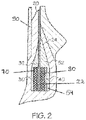
FIG. 2 is a schematic of the bead area shown with the inner liner, a first apex and a second apex; and -
FIG. 3A is a first embodiment of the second apex, whileFIG. 3B is a second embodiment of the second apex. -
FIG. 1 illustrates atire 10 of the present invention that has no bead turnup, i.e. no carcass ply turning about the bead and forming a carcass ply turnup portion. - The
tire 10 further includes atread 500, aninner liner 90 and one ormore belts belts - Preferably, the
tire 10 has only a single layer or monolayer ofply 20, that has a radiallyinner portion 22 that is clamped between a first bead 30 (or bead column) and a second bead 40 (or bead column). - In one embodiment, the
ply layer 20 comprises radial cords that may be formed of a high modulus 2200/3 denier cords or 3340/2 denier cords. The cord material may be nylon, aramid, or a hybrid construction of nylon/aramid. Thelower ply end 22 is clamped between thefirst bead 30 and thesecond bead 40. - The
first bead 30 is a column bead bundle, preferably a double column bead bundle that may range from 2 by 6 to 2 by 13, i.e. 2 rows with 6 to 13wires 70 in each row. In one embodiment, thefirst bead 30 is formed of metal orsteel wire 70, with a 0.89 mm diameter or a 1.295 mm diameter for instance. Thefirst bead 30 may be pre-formed and then applied onto the tire building drum. An optional first apex 32 as depicted inFIG. 2 may be positioned radially outward of thefirst bead column 30. - The tire further includes a second or axially outer bead or
bead column 40 that functions to clamp the ply ending 22 between the first andsecond beads outer bead 40 is a flexible bead and/or formed of multifilament extensible cord. - Preferably, the
second bead 40 is a column bead bundle, more preferably a double column bead bundle that may range from 2 by 6 to 2 by 13, i.e. 2 rows with 6 to 13cords 80 in each row. In one embodiment, thesecond bead 40 is formed of extensible steel cords with multiple filaments, the filaments preferably having a diameter in a range of from 0.28 mm to 0.42 mm. An optional second apex 50, 60 as depicted inFIG. 2 may be positioned radially outward of thesecond bead column 40. - Preferably, the axially
outer bead 40 is spirally wound directly onto the ply ending 22 during the tire building process. In a preferred embodiment, the axiallyouter bead 40 is formed from an extensible cord. - A
second apex outer bead 40. Thesecond apex outer portion ply 20 and achafer 24. Thesecond apex inner lip outer bead 40. Thesecond apex - The
second apex 50 is preferably mechanically locked to thesecond bead 40 and the surrounding area, minimizing or eliminating the ply slippage during the tire building process and shaping process. - A first embodiment of a
second apex 50 is shown inFIG. 2 andFIG. 3A . The radially uppertriangular portion 52 width is adapted to the width of the second flexible bead. Thenarrow lip portion 54 width preferably ranges from 0.3 mm to 0.8 mm.FIG. 3B illustrates a second embodiment of thesecond apex 60, that has a reduced radial height, and a wider lip in a range of from 0.8 mm to 1.2 mm. Overall, thelip portion 54 preferably has a thickness in a range of from 0.3 to 1.2 mm. - The stiffness may be characterized by the dynamic modulus G', which are sometimes referred to as the "shear storage modulus" or "dynamic modulus," reference may be made to Science and Technology of Rubber, second edition, 1994, Academic Press, San Diego, Calif., edited by James E. Mark et al, pages 249-254. The shear storage modulus (G') values are indicative of rubber compound stiffness which can relate to tire performance. The tan delta value at 100 ºC is considered as being indicative of hysteresis, or heat loss.
- In a first embodiment, the
second apex second apex 50 comprises a rubber composition having a shear storage modulus G' measured at 1% strain and 100 ºC according to ASTM D5289 ranging from 23 to 43 MPa.
Claims (14)
- A tire having a tread, a layer of carcass ply (20) having a radially inner end (22), a first column bead (30) and a second bead or column bead (40), wherein the radially inner end (22) of the layer of ply (20) is secured between the first column bead (30) and the second bead or column bead (40), wherein the first column bead (30) comprises or consists of a first bead wire (70) or cord and the second bead or column bead (40) comprises or consist of a second bead wire (80) or cord, characterized in that one of the first and second bead wire or cord (70, 80) has an elongation at 10% of the breaking load greater than 0.2%, when measured from a wire or cord extracted from a cured tire, and the respective other of the first or second bead wire or cord (70, 80) has an elongation at 10% of the breaking load less than 0.2%, when measured from a wire or cord extracted from a cured tire, and in that the first column bead (30) comprises or consists of steel wire (70) and the second bead or column bead (40) comprises or consists of steel cords (80) comprising a plurality of steel filaments twisted together.
- The tire of claim 1 wherein one of the first and second bead wire or cord (70, 80) has an elongation at 10% of the breaking load greater than 0.4% or greater than 0.8% when measured from a wire or cord extracted from a cured tire.
- The tire of claim 1 or 2 wherein one of the first or second bead wire or cord (70, 80) has an elongation at 10% of the breaking load less than 0.15% or less than 0.1%, when measured from a wire or cord extracted from a cured tire.
- The tire of at least one of the previous claims wherein the tire (10) has only a single layer of carcass ply (20).
- The tire of at least one of the previous claims 1 to 3 wherein the tire (10) has more than one layer of carcass ply (20), wherein (i) at least two of these layers of carcass ply (20) are secured between the first column bead (30) and the second bead or column bead (40); or (ii) wherein only a single layer of carcass ply (20) is secured between the first column bead (30) and the second bead or column bead (40).
- The tire of at least one of the previous claims wherein the first column bead (30) is on the axially inner side of the secured layer of carcass ply (20) and the first bead wire (70) has an elongation at 10% of the breaking load less than 0.2%, preferably less than less than 0.15% or less than 0.1%, when measured from a wire extracted from a cured tire, and wherein the second bead or column bead (40) is on the axially outer side of the secured layer of carcass ply (20) and the second bead cord (80) has an elongation at 10% of the breaking load greater than 0.2%, preferably greater than 0.4% or greater than 0.8%, when measured from a cord extracted from a cured tire.
- The tire of at least one of the previous claims further including a first, preferably substantially triangular shaped apex (32) located radially outward of the first column bead (30) and/or further including a second, preferably substantially triangular shaped apex (52) located radially outward of the second bead or column bead (40).
- The tire of at least one of the previous claims wherein the second bead or column bead (40) is on the axially outer side of the secured layer of carcass ply (20) and wherein the second apex (52) has a substantially triangular shaped apex portion (52) and a lip portion (54) extending radially inward from the substantially triangular shaped apex portion (52).
- The tire of claim 8 wherein the lip portion (54) is positioned against the second bead or column bead (40) and/or extends along the second bead or column bead (40), preferably along the full radial height of the second bead or column bead (40).
- The tire of at least one of the previous claims wherein the first column bead (30) comprises or is formed of single steel bead wires (70), preferably with a wire diameter in a range of from 0.89 mm to 1.83 mm.
- The tire of claim 10 wherein the single steel bead wires (70) have a tensile strength in the range of from 2100 to 2500 MPa.
- The tire of claim 10 or 11 wherein the single steel bead wires (70) have a minimum percent elongation to break of 5%, preferably of 6%, as tested according to ASTM D4975.
- The tire of at least one of the previous claims wherein the second bead or column bead (40) comprises or is formed of steel cords with multiple filaments, said filaments having a diameter in a range of from 0.28 mm to 0.42 mm.
- The tire of at least one of the previous claims wherein the second bead or column bead (40) comprises or is formed of steel cords having a tensile strength below 3500 MPa or below 3000 MPa.
Applications Claiming Priority (2)
| Application Number | Priority Date | Filing Date | Title |
|---|---|---|---|
| US201862782484P | 2018-12-20 | 2018-12-20 | |
| US16/655,289 US20200198411A1 (en) | 2018-12-20 | 2019-10-17 | Tire with no ply turnup |
Publications (2)
| Publication Number | Publication Date |
|---|---|
| EP3677443A1 EP3677443A1 (en) | 2020-07-08 |
| EP3677443B1 true EP3677443B1 (en) | 2022-11-02 |
Family
ID=69411027
Family Applications (1)
| Application Number | Title | Priority Date | Filing Date |
|---|---|---|---|
| EP19218344.0A Active EP3677443B1 (en) | 2018-12-20 | 2019-12-19 | Tire with a clamped carcass ply |
Country Status (2)
| Country | Link |
|---|---|
| US (1) | US20200198411A1 (en) |
| EP (1) | EP3677443B1 (en) |
Families Citing this family (1)
| Publication number | Priority date | Publication date | Assignee | Title |
|---|---|---|---|---|
| US20220185016A1 (en) * | 2020-12-16 | 2022-06-16 | The Goodyear Tire & Rubber Company | Non-pneumatic tire |
Family Cites Families (6)
| Publication number | Priority date | Publication date | Assignee | Title |
|---|---|---|---|---|
| FR2736006A1 (en) * | 1995-06-29 | 1997-01-03 | Sedepro | TIRE COMPRISING CIRCUMFERENTIAL CABLES FOR ANCHORING THE CARCASS, PROCESS FOR PREPARING SUCH CABLES |
| CN1152792C (en) * | 1998-12-07 | 2004-06-09 | 倍耐力轮胎公司 | Wheel tires with improved bead construction |
| WO2001036219A1 (en) * | 1999-11-18 | 2001-05-25 | Société de Technologie Michelin | Tyre with low zone comprising a concentration of wires |
| AU2001281889A1 (en) * | 2000-06-29 | 2002-01-08 | Michelin Recherche Et Technique S.A. | Tyre lateral reinforcing element |
| FR2827549A1 (en) * | 2001-07-20 | 2003-01-24 | Michelin Soc Tech | ANCHORING THE CARCASS OF A TIRE |
| FR2870264B1 (en) * | 2004-05-12 | 2006-07-14 | Michelin Soc Tech | METAL CABLE FOR TIRES |
-
2019
- 2019-10-17 US US16/655,289 patent/US20200198411A1/en not_active Abandoned
- 2019-12-19 EP EP19218344.0A patent/EP3677443B1/en active Active
Also Published As
| Publication number | Publication date |
|---|---|
| EP3677443A1 (en) | 2020-07-08 |
| US20200198411A1 (en) | 2020-06-25 |
Similar Documents
| Publication | Publication Date | Title |
|---|---|---|
| US10421320B2 (en) | Pneumatic vehicle tire | |
| EP0855964B1 (en) | A thin gauge, fine diameter steel cord reinforced tire ply fabric and a method of lap splicing the fabric | |
| EP1162087B1 (en) | Pmeumatic tyre | |
| EP3000624B1 (en) | Pneumatic tire | |
| CN115997056B (en) | Double layer multi-strand cable with improved flex durability | |
| US9073389B2 (en) | All steel fabric radial construction for agricultural tires | |
| US20030034108A1 (en) | Tire bead with textile plies | |
| EP3643519A1 (en) | Pneumatic tire | |
| EP3677443B1 (en) | Tire with a clamped carcass ply | |
| US20220185034A1 (en) | Tire with improved bead structure | |
| CN109982868A (en) | Hoop reinforcement for tires of heavy civil engineering vehicles | |
| EP4011645B1 (en) | Truck tire | |
| EP3643529A1 (en) | Bead core, production method therefor, and pneumatic tire | |
| CN1729110B (en) | Run-flat tire with variable stiffness sidewalls | |
| US20110232818A1 (en) | Tire for Heavy Vehicles Comprising at Least in Each Shoulder, at Least Two Additional Layers in the Crown Reinforcement | |
| CN114555347A (en) | Tire having improved uniformity and method of making same | |
| EP1674295A2 (en) | Pneumatic run-flat tire | |
| EP3785946B1 (en) | Tire with clamped ply | |
| US20180257436A1 (en) | Pneumatic vehicle tire | |
| EP4015253B1 (en) | Tire with improved bead structure | |
| EP3643487A1 (en) | Pneumatic tire production method | |
| EP3785947B1 (en) | Tire with clamped carcass ply | |
| JP4593286B2 (en) | Aircraft tires | |
| EP3081395A1 (en) | A continuous crown reinforcement for a pneumatic tire | |
| EP3643520A1 (en) | Pneumatic tire |
Legal Events
| Date | Code | Title | Description |
|---|---|---|---|
| PUAI | Public reference made under article 153(3) epc to a published international application that has entered the european phase |
Free format text: ORIGINAL CODE: 0009012 |
|
| STAA | Information on the status of an ep patent application or granted ep patent |
Free format text: STATUS: THE APPLICATION HAS BEEN PUBLISHED |
|
| AK | Designated contracting states |
Kind code of ref document: A1 Designated state(s): AL AT BE BG CH CY CZ DE DK EE ES FI FR GB GR HR HU IE IS IT LI LT LU LV MC MK MT NL NO PL PT RO RS SE SI SK SM TR |
|
| AX | Request for extension of the european patent |
Extension state: BA ME |
|
| STAA | Information on the status of an ep patent application or granted ep patent |
Free format text: STATUS: REQUEST FOR EXAMINATION WAS MADE |
|
| 17P | Request for examination filed |
Effective date: 20210111 |
|
| RBV | Designated contracting states (corrected) |
Designated state(s): AL AT BE BG CH CY CZ DE DK EE ES FI FR GB GR HR HU IE IS IT LI LT LU LV MC MK MT NL NO PL PT RO RS SE SI SK SM TR |
|
| STAA | Information on the status of an ep patent application or granted ep patent |
Free format text: STATUS: EXAMINATION IS IN PROGRESS |
|
| 17Q | First examination report despatched |
Effective date: 20210525 |
|
| GRAP | Despatch of communication of intention to grant a patent |
Free format text: ORIGINAL CODE: EPIDOSNIGR1 |
|
| STAA | Information on the status of an ep patent application or granted ep patent |
Free format text: STATUS: GRANT OF PATENT IS INTENDED |
|
| INTG | Intention to grant announced |
Effective date: 20220518 |
|
| RIN1 | Information on inventor provided before grant (corrected) |
Inventor name: DEHEZ, GERMAIN Inventor name: COX, HUBERT ANNA JOHANES Inventor name: MARECHAL, FREDERIC Inventor name: LIONETTI, ROBERT EDWARD Inventor name: SOULTIS, NICOLAS Inventor name: DI PRIZIO, OLIVIER Inventor name: MULLER, PHILIPPE JOSEPH AUGUSTE Inventor name: BONNET, GILLES Inventor name: REICHLING, GILLES |
|
| GRAS | Grant fee paid |
Free format text: ORIGINAL CODE: EPIDOSNIGR3 |
|
| GRAA | (expected) grant |
Free format text: ORIGINAL CODE: 0009210 |
|
| STAA | Information on the status of an ep patent application or granted ep patent |
Free format text: STATUS: THE PATENT HAS BEEN GRANTED |
|
| AK | Designated contracting states |
Kind code of ref document: B1 Designated state(s): AL AT BE BG CH CY CZ DE DK EE ES FI FR GB GR HR HU IE IS IT LI LT LU LV MC MK MT NL NO PL PT RO RS SE SI SK SM TR |
|
| REG | Reference to a national code |
Ref country code: GB Ref legal event code: FG4D |
|
| REG | Reference to a national code |
Ref country code: CH Ref legal event code: EP Ref country code: AT Ref legal event code: REF Ref document number: 1528511 Country of ref document: AT Kind code of ref document: T Effective date: 20221115 |
|
| REG | Reference to a national code |
Ref country code: DE Ref legal event code: R096 Ref document number: 602019021398 Country of ref document: DE |
|
| REG | Reference to a national code |
Ref country code: IE Ref legal event code: FG4D |
|
| REG | Reference to a national code |
Ref country code: LT Ref legal event code: MG9D |
|
| REG | Reference to a national code |
Ref country code: NL Ref legal event code: MP Effective date: 20221102 |
|
| REG | Reference to a national code |
Ref country code: AT Ref legal event code: MK05 Ref document number: 1528511 Country of ref document: AT Kind code of ref document: T Effective date: 20221102 |
|
| PG25 | Lapsed in a contracting state [announced via postgrant information from national office to epo] |
Ref country code: SE Free format text: LAPSE BECAUSE OF FAILURE TO SUBMIT A TRANSLATION OF THE DESCRIPTION OR TO PAY THE FEE WITHIN THE PRESCRIBED TIME-LIMIT Effective date: 20221102 Ref country code: PT Free format text: LAPSE BECAUSE OF FAILURE TO SUBMIT A TRANSLATION OF THE DESCRIPTION OR TO PAY THE FEE WITHIN THE PRESCRIBED TIME-LIMIT Effective date: 20230302 Ref country code: NO Free format text: LAPSE BECAUSE OF FAILURE TO SUBMIT A TRANSLATION OF THE DESCRIPTION OR TO PAY THE FEE WITHIN THE PRESCRIBED TIME-LIMIT Effective date: 20230202 Ref country code: LT Free format text: LAPSE BECAUSE OF FAILURE TO SUBMIT A TRANSLATION OF THE DESCRIPTION OR TO PAY THE FEE WITHIN THE PRESCRIBED TIME-LIMIT Effective date: 20221102 Ref country code: FI Free format text: LAPSE BECAUSE OF FAILURE TO SUBMIT A TRANSLATION OF THE DESCRIPTION OR TO PAY THE FEE WITHIN THE PRESCRIBED TIME-LIMIT Effective date: 20221102 Ref country code: ES Free format text: LAPSE BECAUSE OF FAILURE TO SUBMIT A TRANSLATION OF THE DESCRIPTION OR TO PAY THE FEE WITHIN THE PRESCRIBED TIME-LIMIT Effective date: 20221102 Ref country code: AT Free format text: LAPSE BECAUSE OF FAILURE TO SUBMIT A TRANSLATION OF THE DESCRIPTION OR TO PAY THE FEE WITHIN THE PRESCRIBED TIME-LIMIT Effective date: 20221102 |
|
| PG25 | Lapsed in a contracting state [announced via postgrant information from national office to epo] |
Ref country code: RS Free format text: LAPSE BECAUSE OF FAILURE TO SUBMIT A TRANSLATION OF THE DESCRIPTION OR TO PAY THE FEE WITHIN THE PRESCRIBED TIME-LIMIT Effective date: 20221102 Ref country code: PL Free format text: LAPSE BECAUSE OF FAILURE TO SUBMIT A TRANSLATION OF THE DESCRIPTION OR TO PAY THE FEE WITHIN THE PRESCRIBED TIME-LIMIT Effective date: 20221102 Ref country code: LV Free format text: LAPSE BECAUSE OF FAILURE TO SUBMIT A TRANSLATION OF THE DESCRIPTION OR TO PAY THE FEE WITHIN THE PRESCRIBED TIME-LIMIT Effective date: 20221102 Ref country code: IS Free format text: LAPSE BECAUSE OF FAILURE TO SUBMIT A TRANSLATION OF THE DESCRIPTION OR TO PAY THE FEE WITHIN THE PRESCRIBED TIME-LIMIT Effective date: 20230302 Ref country code: HR Free format text: LAPSE BECAUSE OF FAILURE TO SUBMIT A TRANSLATION OF THE DESCRIPTION OR TO PAY THE FEE WITHIN THE PRESCRIBED TIME-LIMIT Effective date: 20221102 Ref country code: GR Free format text: LAPSE BECAUSE OF FAILURE TO SUBMIT A TRANSLATION OF THE DESCRIPTION OR TO PAY THE FEE WITHIN THE PRESCRIBED TIME-LIMIT Effective date: 20230203 |
|
| PG25 | Lapsed in a contracting state [announced via postgrant information from national office to epo] |
Ref country code: NL Free format text: LAPSE BECAUSE OF FAILURE TO SUBMIT A TRANSLATION OF THE DESCRIPTION OR TO PAY THE FEE WITHIN THE PRESCRIBED TIME-LIMIT Effective date: 20221102 |
|
| PG25 | Lapsed in a contracting state [announced via postgrant information from national office to epo] |
Ref country code: SM Free format text: LAPSE BECAUSE OF FAILURE TO SUBMIT A TRANSLATION OF THE DESCRIPTION OR TO PAY THE FEE WITHIN THE PRESCRIBED TIME-LIMIT Effective date: 20221102 Ref country code: RO Free format text: LAPSE BECAUSE OF FAILURE TO SUBMIT A TRANSLATION OF THE DESCRIPTION OR TO PAY THE FEE WITHIN THE PRESCRIBED TIME-LIMIT Effective date: 20221102 Ref country code: IT Free format text: LAPSE BECAUSE OF NON-PAYMENT OF DUE FEES Effective date: 20221219 Ref country code: EE Free format text: LAPSE BECAUSE OF FAILURE TO SUBMIT A TRANSLATION OF THE DESCRIPTION OR TO PAY THE FEE WITHIN THE PRESCRIBED TIME-LIMIT Effective date: 20221102 Ref country code: DK Free format text: LAPSE BECAUSE OF FAILURE TO SUBMIT A TRANSLATION OF THE DESCRIPTION OR TO PAY THE FEE WITHIN THE PRESCRIBED TIME-LIMIT Effective date: 20221102 Ref country code: CZ Free format text: LAPSE BECAUSE OF FAILURE TO SUBMIT A TRANSLATION OF THE DESCRIPTION OR TO PAY THE FEE WITHIN THE PRESCRIBED TIME-LIMIT Effective date: 20221102 |
|
| REG | Reference to a national code |
Ref country code: CH Ref legal event code: PL |
|
| REG | Reference to a national code |
Ref country code: DE Ref legal event code: R097 Ref document number: 602019021398 Country of ref document: DE |
|
| REG | Reference to a national code |
Ref country code: BE Ref legal event code: MM Effective date: 20221231 |
|
| PG25 | Lapsed in a contracting state [announced via postgrant information from national office to epo] |
Ref country code: SK Free format text: LAPSE BECAUSE OF FAILURE TO SUBMIT A TRANSLATION OF THE DESCRIPTION OR TO PAY THE FEE WITHIN THE PRESCRIBED TIME-LIMIT Effective date: 20221102 Ref country code: LU Free format text: LAPSE BECAUSE OF NON-PAYMENT OF DUE FEES Effective date: 20221219 Ref country code: AL Free format text: LAPSE BECAUSE OF FAILURE TO SUBMIT A TRANSLATION OF THE DESCRIPTION OR TO PAY THE FEE WITHIN THE PRESCRIBED TIME-LIMIT Effective date: 20221102 |
|
| PLBE | No opposition filed within time limit |
Free format text: ORIGINAL CODE: 0009261 |
|
| STAA | Information on the status of an ep patent application or granted ep patent |
Free format text: STATUS: NO OPPOSITION FILED WITHIN TIME LIMIT |
|
| 26N | No opposition filed |
Effective date: 20230803 |
|
| PG25 | Lapsed in a contracting state [announced via postgrant information from national office to epo] |
Ref country code: LI Free format text: LAPSE BECAUSE OF NON-PAYMENT OF DUE FEES Effective date: 20221231 Ref country code: IE Free format text: LAPSE BECAUSE OF NON-PAYMENT OF DUE FEES Effective date: 20221219 Ref country code: CH Free format text: LAPSE BECAUSE OF NON-PAYMENT OF DUE FEES Effective date: 20221231 |
|
| PG25 | Lapsed in a contracting state [announced via postgrant information from national office to epo] |
Ref country code: SI Free format text: LAPSE BECAUSE OF FAILURE TO SUBMIT A TRANSLATION OF THE DESCRIPTION OR TO PAY THE FEE WITHIN THE PRESCRIBED TIME-LIMIT Effective date: 20221102 Ref country code: BE Free format text: LAPSE BECAUSE OF NON-PAYMENT OF DUE FEES Effective date: 20221231 |
|
| PG25 | Lapsed in a contracting state [announced via postgrant information from national office to epo] |
Ref country code: IT Free format text: LAPSE BECAUSE OF NON-PAYMENT OF DUE FEES Effective date: 20221219 |
|
| PGRI | Patent reinstated in contracting state [announced from national office to epo] |
Ref country code: IT Effective date: 20221231 |
|
| PG25 | Lapsed in a contracting state [announced via postgrant information from national office to epo] |
Ref country code: HU Free format text: LAPSE BECAUSE OF FAILURE TO SUBMIT A TRANSLATION OF THE DESCRIPTION OR TO PAY THE FEE WITHIN THE PRESCRIBED TIME-LIMIT; INVALID AB INITIO Effective date: 20191219 |
|
| PG25 | Lapsed in a contracting state [announced via postgrant information from national office to epo] |
Ref country code: CY Free format text: LAPSE BECAUSE OF FAILURE TO SUBMIT A TRANSLATION OF THE DESCRIPTION OR TO PAY THE FEE WITHIN THE PRESCRIBED TIME-LIMIT Effective date: 20221102 |
|
| PG25 | Lapsed in a contracting state [announced via postgrant information from national office to epo] |
Ref country code: MK Free format text: LAPSE BECAUSE OF FAILURE TO SUBMIT A TRANSLATION OF THE DESCRIPTION OR TO PAY THE FEE WITHIN THE PRESCRIBED TIME-LIMIT Effective date: 20221102 |
|
| PG25 | Lapsed in a contracting state [announced via postgrant information from national office to epo] |
Ref country code: MC Free format text: LAPSE BECAUSE OF FAILURE TO SUBMIT A TRANSLATION OF THE DESCRIPTION OR TO PAY THE FEE WITHIN THE PRESCRIBED TIME-LIMIT Effective date: 20221102 |
|
| PG25 | Lapsed in a contracting state [announced via postgrant information from national office to epo] |
Ref country code: MC Free format text: LAPSE BECAUSE OF FAILURE TO SUBMIT A TRANSLATION OF THE DESCRIPTION OR TO PAY THE FEE WITHIN THE PRESCRIBED TIME-LIMIT Effective date: 20221102 |
|
| PG25 | Lapsed in a contracting state [announced via postgrant information from national office to epo] |
Ref country code: BG Free format text: LAPSE BECAUSE OF FAILURE TO SUBMIT A TRANSLATION OF THE DESCRIPTION OR TO PAY THE FEE WITHIN THE PRESCRIBED TIME-LIMIT Effective date: 20221102 |
|
| GBPC | Gb: european patent ceased through non-payment of renewal fee |
Effective date: 20231219 |
|
| PG25 | Lapsed in a contracting state [announced via postgrant information from national office to epo] |
Ref country code: MT Free format text: LAPSE BECAUSE OF FAILURE TO SUBMIT A TRANSLATION OF THE DESCRIPTION OR TO PAY THE FEE WITHIN THE PRESCRIBED TIME-LIMIT Effective date: 20221102 |
|
| PG25 | Lapsed in a contracting state [announced via postgrant information from national office to epo] |
Ref country code: GB Free format text: LAPSE BECAUSE OF NON-PAYMENT OF DUE FEES Effective date: 20231219 |
|
| PG25 | Lapsed in a contracting state [announced via postgrant information from national office to epo] |
Ref country code: GB Free format text: LAPSE BECAUSE OF NON-PAYMENT OF DUE FEES Effective date: 20231219 |
|
| PG25 | Lapsed in a contracting state [announced via postgrant information from national office to epo] |
Ref country code: TR Free format text: LAPSE BECAUSE OF FAILURE TO SUBMIT A TRANSLATION OF THE DESCRIPTION OR TO PAY THE FEE WITHIN THE PRESCRIBED TIME-LIMIT Effective date: 20221102 |
|
| PGFP | Annual fee paid to national office [announced via postgrant information from national office to epo] |
Ref country code: DE Payment date: 20251126 Year of fee payment: 7 |
|
| PGFP | Annual fee paid to national office [announced via postgrant information from national office to epo] |
Ref country code: IT Payment date: 20251119 Year of fee payment: 7 |
|
| PGFP | Annual fee paid to national office [announced via postgrant information from national office to epo] |
Ref country code: FR Payment date: 20251120 Year of fee payment: 7 |