EP3677442B1 - Off-road tyre - Google Patents
Off-road tyre Download PDFInfo
- Publication number
- EP3677442B1 EP3677442B1 EP19209927.3A EP19209927A EP3677442B1 EP 3677442 B1 EP3677442 B1 EP 3677442B1 EP 19209927 A EP19209927 A EP 19209927A EP 3677442 B1 EP3677442 B1 EP 3677442B1
- Authority
- EP
- European Patent Office
- Prior art keywords
- block
- tyre
- contact surface
- ground contact
- shoulder
- Prior art date
- Legal status (The legal status is an assumption and is not a legal conclusion. Google has not performed a legal analysis and makes no representation as to the accuracy of the status listed.)
- Active
Links
Images




Classifications
-
- B—PERFORMING OPERATIONS; TRANSPORTING
- B60—VEHICLES IN GENERAL
- B60C—VEHICLE TYRES; TYRE INFLATION; TYRE CHANGING; CONNECTING VALVES TO INFLATABLE ELASTIC BODIES IN GENERAL; DEVICES OR ARRANGEMENTS RELATED TO TYRES
- B60C11/00—Tyre tread bands; Tread patterns; Anti-skid inserts
- B60C11/03—Tread patterns
-
- B—PERFORMING OPERATIONS; TRANSPORTING
- B60—VEHICLES IN GENERAL
- B60C—VEHICLE TYRES; TYRE INFLATION; TYRE CHANGING; CONNECTING VALVES TO INFLATABLE ELASTIC BODIES IN GENERAL; DEVICES OR ARRANGEMENTS RELATED TO TYRES
- B60C11/00—Tyre tread bands; Tread patterns; Anti-skid inserts
- B60C11/03—Tread patterns
- B60C11/11—Tread patterns in which the raised area of the pattern consists only of isolated elements, e.g. blocks
-
- B—PERFORMING OPERATIONS; TRANSPORTING
- B60—VEHICLES IN GENERAL
- B60C—VEHICLE TYRES; TYRE INFLATION; TYRE CHANGING; CONNECTING VALVES TO INFLATABLE ELASTIC BODIES IN GENERAL; DEVICES OR ARRANGEMENTS RELATED TO TYRES
- B60C11/00—Tyre tread bands; Tread patterns; Anti-skid inserts
- B60C11/03—Tread patterns
- B60C11/13—Tread patterns characterised by the groove cross-section, e.g. for buttressing or preventing stone-trapping
- B60C11/1376—Three dimensional block surfaces departing from the enveloping tread contour
-
- B—PERFORMING OPERATIONS; TRANSPORTING
- B60—VEHICLES IN GENERAL
- B60C—VEHICLE TYRES; TYRE INFLATION; TYRE CHANGING; CONNECTING VALVES TO INFLATABLE ELASTIC BODIES IN GENERAL; DEVICES OR ARRANGEMENTS RELATED TO TYRES
- B60C11/00—Tyre tread bands; Tread patterns; Anti-skid inserts
- B60C11/01—Shape of the shoulders between tread and sidewall, e.g. rounded, stepped or cantilevered
- B60C2011/013—Shape of the shoulders between tread and sidewall, e.g. rounded, stepped or cantilevered provided with a recessed portion
-
- B—PERFORMING OPERATIONS; TRANSPORTING
- B60—VEHICLES IN GENERAL
- B60C—VEHICLE TYRES; TYRE INFLATION; TYRE CHANGING; CONNECTING VALVES TO INFLATABLE ELASTIC BODIES IN GENERAL; DEVICES OR ARRANGEMENTS RELATED TO TYRES
- B60C11/00—Tyre tread bands; Tread patterns; Anti-skid inserts
- B60C11/03—Tread patterns
- B60C2011/0337—Tread patterns characterised by particular design features of the pattern
-
- B—PERFORMING OPERATIONS; TRANSPORTING
- B60—VEHICLES IN GENERAL
- B60C—VEHICLE TYRES; TYRE INFLATION; TYRE CHANGING; CONNECTING VALVES TO INFLATABLE ELASTIC BODIES IN GENERAL; DEVICES OR ARRANGEMENTS RELATED TO TYRES
- B60C2200/00—Tyres specially adapted for particular applications
- B60C2200/10—Tyres specially adapted for particular applications for motorcycles, scooters or the like
-
- B—PERFORMING OPERATIONS; TRANSPORTING
- B60—VEHICLES IN GENERAL
- B60C—VEHICLE TYRES; TYRE INFLATION; TYRE CHANGING; CONNECTING VALVES TO INFLATABLE ELASTIC BODIES IN GENERAL; DEVICES OR ARRANGEMENTS RELATED TO TYRES
- B60C2200/00—Tyres specially adapted for particular applications
- B60C2200/14—Tyres specially adapted for particular applications for off-road use
-
- Y—GENERAL TAGGING OF NEW TECHNOLOGICAL DEVELOPMENTS; GENERAL TAGGING OF CROSS-SECTIONAL TECHNOLOGIES SPANNING OVER SEVERAL SECTIONS OF THE IPC; TECHNICAL SUBJECTS COVERED BY FORMER USPC CROSS-REFERENCE ART COLLECTIONS [XRACs] AND DIGESTS
- Y02—TECHNOLOGIES OR APPLICATIONS FOR MITIGATION OR ADAPTATION AGAINST CLIMATE CHANGE
- Y02T—CLIMATE CHANGE MITIGATION TECHNOLOGIES RELATED TO TRANSPORTATION
- Y02T10/00—Road transport of goods or passengers
- Y02T10/80—Technologies aiming to reduce greenhouse gasses emissions common to all road transportation technologies
- Y02T10/86—Optimisation of rolling resistance, e.g. weight reduction
Definitions
- the present invention relates to an off-road motorcycle tyre.
- Patent document 1 discloses an off-road pneumatic tyre which includes a tread portion provided with a plurality of shoulder blocks on a tread edge side.
- the plurality of shoulder blocks is provided with a cut which includes a pair of first sipes extending inwardly toward the block center from a block edge and a second sipe connecting the pair of first sipes.
- the plurality of shoulder blocks comprises a main portion defined outwardly of the cut and an auxiliary portion defined inwardly of the cut.
- Patent document 1 Japanese Unexamined Patent Application Publication 2014-184956 ;
- EP 3 323 641 A1 discloses an off-road motorcycle tyre comprising the features according to the preamble of claim 1.
- EP 3 611 037 A1 being published after the priority date of the present application discloses an off-road motorcycle tyre according to a related technology wherein a second ground contact surface of a shoulder block protrudes outwardly from a first ground contact surface of the shoulder block in a block height direction.
- EP 2 412 547 A1 discloses an off-road motorcycle tyre comprising a shoulder block which includes a first ground contact surface, a second ground contact surface protruding outwardly from the first ground contact surface in a block height direction, and a shallow groove extending between the first ground contact surface and the second ground contact surface.
- EP 3 339 057 A1 discloses an off-road motorcycle tyre according to a related technology.
- JP H01 273706 A discloses a tyre including a tread pattern which includes blocks each comprising an upper block stacked on a lower block, wherein the upper block has a smaller area than the lower block.
- off-road tyre Due to recent improvements in performance of vehicles, opportunity for such an off-road tyre to travel not only off-road conditions such as muddy roads and the like but also hard road surface conditions such as dry asphalt roads, compressed-soil roads and the like has been increased. Thus, it has been required for off-road tyres to exhibit superior steering stability on both off-road conditions and hard road surface conditions.
- the present invention has been made in view of the above problem and has a major object to provide an off-road tyre capable of improving steering stability on both off-road conditions and hard road surface conditions in a well-balanced manner.
- an off-road motorcycle tyre includes a tread portion being provided on a tread edge side with shoulder blocks arranged in a tyre circumferential direction, the shoulder blocks including at least one first shoulder block and at least one second shoulder block having a circumferential length greater than that of the at least one first shoulder block, wherein the at least one first shoulder block includes a first ground contact surface, a second ground contact surface protruding outwardly from the first ground contact surface in a block height direction, and a first shallow groove extending between the first ground contact surface and the second ground contact surface.
- a length in a tyre axial direction of the at least one second shoulder block is greater than a length in a tyre axial direction of the at least one first shoulder block, but is equal to or less than 1.30 times the length in a tyre axial direction of the at least one first shoulder block.
- the at least one second shoulder block may include a third ground contact surface, a fourth ground contact surface protruding outwardly from the third ground contact surface in a block height direction, and a second shallow groove extending between the third ground contact surface and the fourth ground contact surface.
- the at least one second shoulder block may include a circumferentially extending axially inner block edge
- the second shallow groove may include two lateral groove portions extending outwardly in a tyre axial direction from the inner block edge and a longitudinal groove portion connecting axially outer ends of the lateral groove portions.
- the at least one second shoulder block may include a circumferentially extending axially outer block edge, and a length in the tyre circumferential direction of the inner block edge may be smaller than a length in the tyre circumferential direction of the outer block edge.
- each of the lateral groove portions of the at least one second shoulder block may include a first portion extending from the inner block edge, and a second portion connected to the first portion and having a greater width than that of the first portion.
- the third ground contact surface in the at least one second shoulder block, may be defined outside in the tyre circumferential and axial directions of the second shallow groove, and block widths of portions of the third ground contact surface which are adjacent to the second portions of the lateral groove portions in the tyre circumferential direction may be greater than a block width of a portion of the third ground contact surface which is adjacent to the longitudinal groove portion in the tyre axial direction, but may be equal to or less than 3.0 times the block width of a portion of the third ground contact surface which is adjacent to the longitudinal groove portion in the tyre axial direction.
- the fourth ground contact surface may be defined inside in the tyre circumferential and axial directions of the second shallow groove, and the inner block edge of the fourth ground contact surface may extend in parallel with the tyre circumferential direction.
- the third ground contact surface in the at least one second shoulder block, may be defined outside in the tyre circumferential and axial directions of the second shallow groove, and a block width of a portion of the third ground contact surface which is adjacent to the longitudinal groove portion in the tyre axial direction may be in a range of from 0.1 to 0.4 times an axial length of the second shoulder block.
- a length in a tyre axial direction of the fourth ground contact surface may be equal to or more than 0.2 times a length in the tyre axial direction of the second shoulder block.
- a block height of the fourth ground contact surface may be equal to or less than 1.2 times a block height of the third ground contact surface.
- a groove depth of the second shallow groove may be in a range of from 0.010 to 0.35 times a block height of the third ground contact surface.
- a number of the at least one first shoulder block may be greater than a number of the at least one second shoulder block.
- a number of the at least one second shoulder block may be less than 0.5 times a number of the at least one first shoulder block.
- a length in the tyre circumferential direction of the at least one second shoulder block may be equal to or less than 2.0 times a length in the tyre circumferential direction of the at least one first shoulder block.
- FIG. 1 illustrates a cross-sectional view of an off-road tyre (hereinafter, simply may be referred to as "tyre") 1 under a normal state in accordance with an embodiment of the invention.
- tyre off-road tyre
- the "normal state” is such that the tyre 1 is mounted on a standard wheel rim (not illustrated) with a standard pressure but loaded with no tyre load.
- dimensions of the respective portions of tyre 1 are values measured under the normal state.
- the "standard wheel rim” is a wheel rim officially approved for each tyre by standards organizations on which the tyre is based, wherein the standard wheel rim is the "standard rim” specified in JATMA, the "Design Rim” in TRA, and the “Measuring Rim” in ETRTO, for example.
- the "standard pressure” is a standard pressure officially approved for each tyre by standards organizations on which the tyre is based, wherein the standard pressure is the "maximum air pressure” in JATMA, the maximum pressure given in the "Tyre Load Limits at Various Cold Inflation Pressures” table in TRA, and the “Inflation Pressure” in ETRTO, for example.
- the tyre 1 includes a tread portion 2 which, in a cross-sectional view, is curved such that an outer surface thereof protrudes outwardly in the tyre radial direction in an arc-shape manner.
- the tyre 1 according to the present embodiment includes a carcass 5 and a belt layer 6, for example.
- a carcass 5 and a belt layer 6, for example.
- conventional structures may be employed.
- FIG. 2 illustrates a development view of the tread portion 2 of the tyre 1 according to the present embodiment.
- the tread pattern is not limited to the aspect as shown in FIG. 2 .
- the tread portion 2 includes a crown region Cr including the tyre equator C, two middle regions M between which the crown region Cr is located, and two shoulder regions S between which the middle regions M are located.
- Each shoulder region S for example, is a region having a one sixth development width of a tread development width TWe from a respective one of tread edges Te.
- Each middle region M for example, is a region having a one sixth development width of the tread development width TWe from a respective one of the shoulder regions S.
- the tread development width TWe is an axial distance between the tread edges Te when the tread portion 2 is developed on a plane.
- the tread edges Te are defined as axially outermost ground contacting edges of the tread portion 2.
- the tread portion 2 is provided with a plurality of shoulder blocks 8 arranged in the tyre circumferential direction on the tread edge Te side of each shoulder region S. Large lateral force may be applied on or around either one of the tread edges Te when cornering.
- the plurality of shoulder blocks 8 arranged in the tyre circumferential direction can be useful to deliver stable cornering.
- the tread portion 2 is provided with tread grooves 11 to define the shoulder blocks 8, middle blocks 9 and the crown blocks 10. These blocks 8 to 10 raise from a bottom 11s of the tread grooves 11.
- the shoulder blocks 8 include at least one first shoulder block 15 and at least one second shoulder block 16 having a circumferential length greater than that of the first shoulder block 15.
- the second shoulder block 16 increases friction force on hard road surface conditions, resulting in exerting powerful traction when cornering.
- the second shoulder block 16 can be useful to improve steering stability on hard road surface conditions.
- FIG. 3 illustrates an enlarged view of the first shoulder block 15.
- the first shoulder block 15 includes a first ground contact surface 15A, a second ground contact surface 15B protruding outwardly from the first ground contact surface 15A in the block height direction, and a first shallow groove 15C extending between the first ground contact surface 15A and the second ground contact surface 15B.
- a second ground contact surface 15B tends to dig into off-road surface and to increase ground contacting pressure, generating powerful traction.
- the first shallow groove 15C, the first ground contact surface 15A and the second ground contact surface 15B which are different in height can increase an edge length.
- the tyre 1 according to the present embodiment can improve steering stability on both off-road conditions and hard road surface conditions in a well-balanced manner.
- FIG. 4 illustrates an enlarged view of the second shoulder block 16.
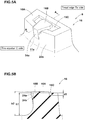
- FIG. 5A illustrates a perspective view of the second shoulder block 16
- FIG. 5B is a cross-sectional view taken along line A-A of FIG. 5A .
- the second shoulder block 16 includes a third ground contact surface 16A, a fourth ground contact surface 16B protruding outwardly from the third ground contact surface 16A in the block height direction, and a second shallow groove 16C extending between the third ground contact surface 16A and the fourth ground contact surface 16B.
- Such a second shoulder block 16 can also improve steering stability on off-road conditions.
- the tyre 1 for traveling on off-road conditions according to the present embodiment which includes the first shoulder block 15 and the second shoulder block 16 can exhibit superior steering stability on off-road conditions.
- the second shoulder block 16 has a line symmetrical shape with respect to an axial line 16h which passes through the circumferential center location of the second shoulder block 16.
- the second shoulder block 16, in the present embodiment has a substantially pentagonal shape. Note that the shape of the second shoulder block 16 is not limited to the above aspect.
- the third ground contact surface 16A in the present embodiment, is configured in a C-shaped manner (or an inverse C-shaped manner).
- the fourth ground contact surface 16B in the present embodiment, has a hexagonal shape whose maximum circumferential length location is positioned axially outwardly of the axial center location of the fourth ground contact surface 16B. Note that shapes of the third ground contact surface 16A and the fourth ground contact surface 16B are not limited to the above aspects.
- the second shoulder block 16 in the present embodiment, includes an axially inner block edge 16i extending in the tyre circumferential direction, and an axially outer block edge 16e extending in the tyre circumferential direction.
- the inner block edge 16i in the present embodiment, includes a pair of end portions 16s formed on the third ground contact surface 16A, and a middle portion 16t formed on the fourth ground contact surface 16B.
- the middle portion 16t in the present embodiment, extends in parallel with the tyre circumferential direction. Such a middle portion 16t may be helpful to enhance axial stiffness of the fourth ground contact surface 16B.
- the end portions 16s in the present embodiment, are inclined with respect to the tyre circumferential direction.
- the end portions 16s for example, extends to the tyre equator C side from circumferential both ends thereof toward the circumferential center location of the second shoulder block 16.
- Such end portions 16s can be helpful to guide mud and the like toward the tread edge Te side smoothly.
- a length L1 in tyre circumferential direction of the inner block edge 16i is smaller than a length L2 in the tyre circumferential direction of the outer block edge 16e. This structure may be helpful to enhance stiffness of the second shoulder block 16 on the tread edge side Te to which large lateral force applies, thus increasing friction force.
- the length L1 in the tyre circumferential direction of the inner block edge 16i is equal to or more than 0.5 times the length L2 in the tyre circumferential direction of the outer block edge 16e.
- stiffness of the second shoulder block 16 on the tyre equator C side may be ensured.
- the length L1 in the tyre circumferential direction of the inner block edge 16i is in a range of from 0.78 to 0.97 times the length L2 in the tyre circumferential direction of the outer block edge 16e.
- the second shoulder block 16 for example, includes two block edges 16j which extends in the tyre circumferential direction on the respective circumferential end portions of the block.
- the block edges 16j in the present embodiment, are inclined outwardly in the tyre circumferential direction of the second shoulder block 16 toward the tread edge Te.
- one of the block edges 16j corresponds to a heel-side edge of the second shoulder block 16
- it can scratch the ground and discharge mud and the like outside the tread edge Te when cornering with a camber angle and a slip angle.
- one of the block edges 16j corresponds to a heel-side edge of the second shoulder block 16
- it can gather mud effectively when braking.
- the block edges 16j can enhance stiffness of the second shoulder block 16 on the tread edge Te side.
- the block edges 16j according to the present embodiment can improve steering stability.
- the second shallow groove 16C includes two lateral groove portions 18 extending outwardly in the tyre axial direction from the inner block edge 16i, and a longitudinal groove portion 19 connecting axially outer ends 18e of the lateral groove portions 18.
- the second shallow groove 16C increases edge component lengths in the tyre axial and circumferential directions.
- the third ground contact surface 16A is separated from the fourth ground contact surface 16B by two lateral groove portions 18 and the longitudinal groove portion 19. Note that the second shallow groove 16C is not limited to such an aspect.
- Each lateral groove portion 18, in the present embodiment includes a first portion 21 extending from the inner block edge 16i, and a second portion 22 connected to the first portion 21 and having a groove width greater than that of the first portion 21.
- the longitudinal groove portion 19, in the present embodiment extends straight in a constant groove width which is measured in parallel with the tyre axial direction.
- the lateral groove portions 18 can mitigate stiffness of the second shoulder block 16 appropriately, improving ground contacting feeling on hard road surface conditions and vibration absorbing property. Further, the second portions 22 of the lateral groove portions 18 can improve scratching effect and facilitate deformation of the fourth ground contact surface 16B, discharging smoothly mud and the like in the second shallow groove 16C located outwardly of the fourth ground contact surface 16B.
- each first portion 21 which is measured in parallel with the tyre circumferential direction is in a range of from 15% to 35% of the groove width W2 of each second portion 22 which is measured in parallel with the tyre circumferential direction.
- Such lateral groove portions 18 can balance stiffness of a portion of the third ground contact surface 16A adjacent to each first portion 21 in the tyre circumferential direction with stiffness of a portion of the third ground contact surface 16A adjacent to each second portion 22 in the tyre circumferential direction, exerting powerful friction force on hard road surface conditions.
- a length L3 in the tyre axial direction of each first portion 21 is smaller than a length L4 in the tyre axial direction of each second portion 22.
- the second portion 22 can generate powerful traction on mud. Further, stiffness of the second shoulder block 16 is mitigated appropriately, improving ground contacting feeling and vibration absorbing property.
- a length L3 in the tyre axial direction of each first portion 21 is preferably in a range of from 60% to 90% of a length L4 in the tyre axial direction of each second portion 22. This can improve the above effect effectively.
- the second shoulder block 16 includes two first block portions 17a and a second block portion 17b.
- Each first block portion 17a is a portion of the third ground contact surface 16A which is adjacent to a respective one of the second portions 22 in the tyre circumferential direction.
- the second block portion 17b is a portion of the third ground contact surface 16A which is adjacent to the longitudinal groove portion 19.
- a block width W3 of each first block portion 17a which is measured in parallel with the tyre circumferential direction is greater than a block width W4 of the second block portion 17b which is measured in parallel with the tyre axial direction.
- Such a second shoulder block 16 can generate high friction force when cornering, exerting powerful traction.
- the block width W3 of each first block portion 17a is equal to or less than 3.0 times the block width W4 of the second block portion 17b.
- the block width W3 of each first block portion 17a exceeds 3.0 times the block width W4 of the second block portion 17b, there is a risk that ground contacting feeling as well as steering stability is deteriorated due to reduction in balance of stiffness in the tyre axial and circumferential directions of the second shoulder block 16.
- the block width W3 of each first block portion 17a is preferably in a range of from 1.2 to 2.5 times the block width W4 of the second block portion 17b.
- the block width W4 of the second block portion 17b is in a range of from 0.1 to 0.4 times a length L5 in the tore axial direction of the second shoulder block 16.
- stiffness of the second shoulder block 16 can be ensured appropriately, improving mud discharging property due to deformation of the fourth ground contact surface 16B, ground contacting feeling, and steering stability in a well-balanced manner.
- the block width W4 of the second block portion 17b is preferably in a range of from 0.15 to 0.35 times the length L5 in the tyre axial direction of the second shoulder block 16.
- a groove width W5 of the longitudinal groove portion 19 which is measured in parallel with the tyre axial direction is in a range of from 5% to 15% of the length L5 in the tyre axial direction of the second shoulder block 16.
- Such a longitudinal groove portion 19 can facilitate deformation of the fourth ground contact surface 16B, discharging mud and the like smoothly while preventing an excessive reduction in stiffness in the tyre axial direction of the second shoulder block 16.
- a length L6 in the tyre axial direction of the fourth ground contact surface 16B is equal to or more than 0.2 times the length L5 in the tyre axial direction of the second shoulder block 16.
- This structure makes it possible to ensure sufficient stiffness of the fourth ground contact surface 16B which results in discharging mud and the like smoothly.
- the length L6 in the tyre axial direction of the fourth ground contact surface 16B is in a range of from 0.5 to 0.8 times the length L5 in the tyre axial direction of the second shoulder block 16.
- a block height h2 of the fourth ground contact surface 16B is equal to or less than 1.2 times a block height h1 of the third ground contact surface 16A. This can prevent excessive deformation of the fourth ground contact surface 16B, thus preventing it from chipping and cracking. In order to further improve the above effect, it is preferable that the block height h2 of the fourth ground contact surface 16B is in a range of from 1.05 to 1.10 times the block height h1 of the third ground contact surface 16A.
- a groove depth d1 of the second shallow groove 16C is in a range of from 0.010 to 0.35 times the block height h1 of the third ground contact surface 16A.
- the groove depth d1 is less than 0.010 times the block height h1, there is a risk that ground contacting feeling as well as vibration absorbing property is deteriorated. Further, deformation of the fourth ground contact surface 16B may be suppressed which deteriorates smooth release of mud and the like.
- the groove depth d1 exceeds 0.35 times the block height h1, stiffness of the second shoulder block 16 tends to decrease excessively.
- the groove depth d1 of the second shallow groove 16C is preferably in a range of from 0.030 to 0.30 times the block height h1 of the third ground contact surface 16A.
- the second shoulder block 16 includes a first block wall 24a extending toward the bottom 11s from the fourth ground contact surface 16B, and a second block wall 24b extending inwardly in the tyre radial direction from the third ground contact surface 16A.
- the first block wall 24a protrudes outwardly of the second shoulder block 16 from the second block wall 24b.
- Such a second shoulder block 16 can improve shearing force on off-road conditions.
- the maximum length in the tyre circumferential direction of the second shoulder block 16, e.g., corresponding to the length L2, is in a range of from 0.010 to 0.10 times, more preferably of from 0.03 to 0.08 times an outer tyre diameter Dt (shown in FIG. 1 ).
- the length L5 in the tyre axial direction is in a range of from 0.050 to 0.3 times, more preferably 0.1 to 0.2 times a tyre overall width TW (shown in FIG. 1 ).
- the block height h1 of the third ground contact surface 16A is in a range of from 0.01 to 0.06 times, more preferably 0.01 to 0.05 times the outer tyre diameter Dt.
- the "tyre overall width TW" shall mean the maximum width in the tyre axial direction of the tyre under the normal state.
- the tyre overall width TW corresponds to a length in the tyre axial direction between the tread edges Te.
- FIG. 6A illustrates a perspective view of the first shoulder block 15, and FIG. 6B illustrates a cross-sectional view taken along line B-B of FIG. 6A .
- the first shoulder block 15 according to the present embodiment is configured as a line symmetrical manner with respect to an axial line 15h which passes through the center location in the tyre circumferential direction of the block.
- the first shoulder block 15, in the present embodiment has a substantially pentagonal shape. Note that the shape of first shoulder block 15 is not limited to the above aspect.
- the first ground contact surface 15A in the present embodiment, has a lateral U-shaped manner.
- the second ground contact surface 15B in the present embodiment, has a substantially hexagonal shape whose maximum circumferential length location is positioned toward the tread edge Te with respect to the axial center location thereof. Note that shapes of the first ground contact surface 15A and the second ground contact surface 15B are not limited to the above aspects.
- the first shoulder block 15 for example, includes a first inner block edge 15i which extends in the tyre circumferential direction on an axially inner side of the block, and a first outer block edge 15e which extends in the tyre circumferential direction on an axially outer side of the block.
- the first inner block edge 15i in the present embodiment, includes a first central portion 15t forming an edge of the second ground contact surface 15B.
- the first central portion 15t in the present embodiment, extends in parallel with the tyre circumferential direction. Such a first central portion 15t can provide the second ground contact surface 15B with high stiffness in the tyre axial direction.
- a length L8 in the tyre circumferential direction of the first inner block edge 15i is smaller than a length L9 in the tyre circumferential direction of the first outer block edge 15e.
- the first shoulder block 15 for example, includes two first block edges 15j which extends in the tyre axial direction on the respective circumferential end portions of the block.
- the first block edges 15j in the present embodiment, are inclined outwardly in the tyre circumferential direction of the first shoulder block 15 toward the tread edge Te.
- Such a first block edges 15j can discharge mud and soil in the tread grooves 11 toward the tread edge Te smoothly when cornering.
- the first shallow groove 15C includes two lateral groove portions 25 extending outwardly in the tyre axial direction from the first inner block edge 15i and a longitudinal groove portion 26 connecting outer ends 25e of the lateral groove portions 25.
- the first ground contact surface 15A is separated from the second ground contact surface 15B by two lateral groove portions 25 and the longitudinal groove portion 26.
- the first shallow groove 15C is not limited to such an aspect but can be modified so as to extend in a wavy or zigzag manner, for example.
- Each lateral groove portion 25, in the present embodiment, includes a third portion 25a and a fourth portion 25b.
- the third portion 25a extends outwardly in the tyre circumferential direction from the first inner block edge 15i of the first shoulder block 15.
- the fourth portion 25b is connected to the third portion 25a, and is inclined in an opposite direction to that of the third portion 25a.
- the lateral groove portions 25, for example, has a constant groove width W8 measured in parallel with the tyre circumferential direction.
- the longitudinal groove portion 26, in the present embodiment extends straight with a constant groove width W9 measured in parallel with the tyre axial direction.
- Such a first shallow groove 15C increases edge lengths thereof in both tyre circumferential and axial directions.
- each lateral groove portion 25 is smaller than the groove width W9 of the longitudinal groove portion 26.
- the second ground contact surface 15B is promoted to deform in the tyre axial direction as compared to in the tyre circumferential direction, enabling to discharge smoothly mud and the like in the tread groove 11 located inwardly in the tyre axial direction of the second ground contact surface 15B. Further, high stiffness of the first shoulder block 15 in the tyre circumferential direction can be maintained.
- a length L10 in the tyre axial direction of the second ground contact surface 15B is equal to or more than 0.2 times a length L11 in the tyre axial direction of the first shoulder block 15.
- the length L10 in the tyre axial direction of the second ground contact surface 15B is in a range of from 0.5 to 0.8 times the length L11 in the tyre axial direction of the second shoulder block 16.
- a block height h4 of the second ground contact surface 15B is equal to or less than 1.2 times a block height h3 of the first ground contact surface 15A.
- the block height h4 of the second ground contact surface 15B is more preferably in a range of from 1.05 to 1.10 times the block height h3 of the first ground contact surface 15A.
- a groove depth d2 of the first shallow groove 15C is in a range of from 0.010 to 0.35 times the block height h3 of the first ground contact surface 15A.
- stiffness of the first shoulder block 15 may be excessive high, deteriorating ground contacting feeling.
- the second ground contact surface 15B may hardly deform which prevents smooth mud discharging.
- stiffness of the first shoulder block 15 may be excessively low.
- the groove depth d2 of the first shallow groove 15C is in a range of from 0.030 to 0.30 times the block height h3 of the first ground contact surface 15A.
- the first shoulder block 15 includes a first block wall 30a extending toward the bottom 11s from the second ground contact surface 15B, and a second block wall 30b extending inwardly in the tyre radial direction from the first ground contact surface 15A.
- the first block wall 30a protrudes outwardly of the first shoulder block 15 from the second block wall 30b.
- Such a first shoulder block 15 can generate powerful traction on off-road.
- the at least one first shoulder block 15 includes a plurality of first shoulder blocks 15, and the at least one second shoulder block 16 includes a plurality of second shoulder blocks 16.
- the number of first shoulder blocks 15 is preferably greater than the number of second shoulder blocks 16. Since the tyre 1 according to the present embodiment is typically directed to off-road traveling, when the number of first shoulder blocks 15 is greater than that of the second shoulder blocks 16, high steering stability on off-road can be maintained.
- the number of second shoulder blocks 16 is less than 0.5 times the number of first shoulder blocks 15.
- the number of second shoulder blocks 16 is more preferably in a range of from 0.10 to 0.40 times the number of first shoulder blocks 15.
- the maximum length in the tyre circumferential direction of the second shoulder blocks 16, e.g., corresponding to the length L2, is equal to or less than 2.0 times the maximum length in the tyre circumferential direction of the first shoulder blocks 15, e.g., corresponding to the length L9.
- the maximum length in the tyre circumferential direction of the second shoulder blocks 16 is preferably in a range of from 1.2 to 1.8 times the maximum length in the tyre circumferential direction of the first shoulder blocks 15.
- each second shoulder block 16 is greater than the length L11 in the tyre axial direction of each first shoulder block 15.
- Such a second shoulder block 16 may have high stiffness in the tyre axial direction, generating powerful lateral force.
- the second shoulder blocks 16 may be difficult to dig into off-road, resulting in deteriorating steering stability.
- the length L5 in the tyre axial direction of each second shoulder block 16 is equal to or less than 1.30 times the length L11 in the tyre axial direction of each first shoulder block 15.
- the length L5 in the tyre axial direction of each second shoulder block 16 is in a range of from 1.02 to 1.10 times the length L11 in the tyre axial direction of each first shoulder block 15.
- the tread portion 2 includes the middle blocks 9 and the crown blocks 10.
- the middle blocks 9 as well as the crown blocks 10 are arranged in the tyre circumferential direction.
- the middle blocks 9, in the present embodiment have respective center of figures located in the middle regions M.
- the crown blocks 10, in the present embodiment have respective center of figures located in the crown region Cr. Note that when a ground contact surface of either one of blocks 9 and 10 is provided with one or more recess such as a shallow grooves and the like, the center of figure of the block is determined based on a virtual ground contact surface of the block which is obtained by filling up all the recesses.
- FIG. 7 illustrates a plan view of one of the middle blocks 9.
- each middle block 9 according to the present embodiment includes a first middle ground contact surface 9A and a second middle ground contact surface 9B protruding outwardly in a block height direction from the first middle ground contact surface 9A, and a middle shallow groove 9C extending between the first middle ground contact surface 9A and the second middle ground contact surface 9B.
- Each middle block 9 for example, includes an axially inner middle block edge 9i extending in the tyre circumferential direction, and an axially outer middle block edge 9e extending in the tyre circumferential direction.
- Each middle block 9 according to the present embodiment has a line symmetrical shape with respect to a tyre axial line 9h that passes the center location in the tyre circumferential direction of the block.
- Each middle block 9, in the present embodiment is configured as a pentagonal shape.
- the middle shallow groove 9C includes two middle lateral groove portions 37 extending in the tyre axial direction from the outer middle block edge 9e, and a middle longitudinal groove portion 38 connecting ends of the middle lateral groove portions 37.
- the first middle ground contact surface 9A in the present embodiment, is separated from the second middle ground contact surface 9B by the middle lateral groove portions 37 and the middle longitudinal groove portion 38.
- Each middle lateral groove portion 37 includes a first lateral portion 37a which extends toward the tyre equator C from the outer middle block edge 9e while inclining toward outwardly in the tyre circumferential direction of the middle block 9. and a second lateral portion 37b which is connected to the first lateral portion 37a with an opposite inclination to that of the first lateral portion 37a.
- Each middle lateral groove portion 37 for example, has a constant groove width, wherein the groove width is measured in parallel with the tyre circumferential direction.
- the middle longitudinal groove portion 38 in the present embodiment, extends straight with a constant groove width, wherein the groove width is measured in parallel with the tyre axial direction.
- the middle lateral groove portions 37 as such may increase edge lengths in both tyre circumferential and axial directions.
- each middle block 9, in the present embodiment includes first middle blocks 40 arranged on the tyre equator C side and second middle blocks 41 arranged axially outwardly of the first middle blocks 40.
- the first middle blocks 40 are arranged so as to overlap the second middle blocks 41 in the tyre axial direction.
- the crown blocks 10, in the present embodiment, include first crown blocks 10A, second crown blocks 10B, and third crown blocks 10C.
- the first crown blocks 10A are located within the crown region Cr.
- the second crown blocks 10B are arranged so as to straddle the crown region Cr and one of the middle regions M (the left side in FIG. 2 ).
- the third crown blocks 10C are arranged so as to straddle the crown region Cr and the other one of the middle regions M (the right side in FIG. 2 ).
- at least either one of first crown blocks 10A, second crown blocks 10B, third crown bocks 10C, first middle blocks 40, or second middle blocks 41 is arranged on an arbitrary tyre circumferential line passing in the crown region Cr and the middle regions M.
- Each crown block 10 is provided with a circumferentially extending shallow groove 10f.
- the shallow roove 10f is located on the center position in the tyre axial direction of the block.
- each crown block 10 is divided into the block pieces 10a.
- the shallow groove 10f helps to increase an edge length of each crown block 10 in the tyre circumferential direction. It is preferable that the shallow groove 10f has a width Wa in a range of from 5% to 25% of a length LA in the tyre axial direction of the crown block 10 and a depth da (shown in FIG. 1 ) in a range of from 5% to 50% of a block height ha of the crown block 10.
- the first crown blocks 10A are configured as non-shifted block which includes two block pieces 10a arranged in the same location in the tyre circumferential direction, i.e., having no circumferential displacement.
- the second crown blocks 10B and the third crown blocks 10C are configured as a shifted-block which includes two block pieces 10a each arranged at a different location in the tyre circumferential direction, i.e., having a displacement from one another.
- the tread grooves 11 are provided with one or more tie-bars 12 which raise bottom thereof to connect two blocks.
- the tie-bars 12 helps to enhance stiffness of blocks, increasing shearing force on off-road as well as friction force on hard road surface conditions.
- the tie-bars 12 include shoulder tie-bars 12A which connect one of the shoulder blocks 8 and one of the middle blocks 9, and middle tie-bars 12B which connect one of the middle blocks 9 and one of the crown blocks 10.
- Road adaptability, sliding controllability, and cornering traction performance test A test rider rode a motocross bike having displacement of 450 cc and equipped with the respective test tyres on off-road test course which includes a muddy road part and a compressed soil part having a hard road surface, and then evaluated road adaptability, sliding controllability and cornering traction performance based on the rider's sense.
- the road adaptability means comprehensive steering stability on both hard road surface and muddy road.
- the sliding controllability means driving controllability when sliding on off-road.
- the cornering traction means driving stability on both hard road surface and muddy road.
- the test results are shown in 10-grade evaluation where 10 is the best. The test results are shown in Table 1. [Table 1] Ref. Ex. 1 Ex.
- example tyres improve steering stability on both off-road and hard road surface conditions in a well-balanced manner. Further, the same test results were confirmed when the present invention was embodied as heavy-duty tyres as well as tyres different in size.
Landscapes
- Engineering & Computer Science (AREA)
- Mechanical Engineering (AREA)
- Tires In General (AREA)
Description
- The present invention relates to an off-road motorcycle tyre.
- The following
Patent document 1 discloses an off-road pneumatic tyre which includes a tread portion provided with a plurality of shoulder blocks on a tread edge side. The plurality of shoulder blocks is provided with a cut which includes a pair of first sipes extending inwardly toward the block center from a block edge and a second sipe connecting the pair of first sipes. Thus, the plurality of shoulder blocks comprises a main portion defined outwardly of the cut and an auxiliary portion defined inwardly of the cut. - [Patent document 1]
Japanese Unexamined Patent Application Publication2014-184956 -
EP 3 323 641 A1 discloses an off-road motorcycle tyre comprising the features according to the preamble ofclaim 1. -
EP 3 611 037 A1 being published after the priority date of the present application discloses an off-road motorcycle tyre according to a related technology wherein a second ground contact surface of a shoulder block protrudes outwardly from a first ground contact surface of the shoulder block in a block height direction. -
EP 2 412 547 A1 -
EP 3 339 057 A1 discloses an off-road motorcycle tyre according to a related technology. -
JP H01 273706 A - Due to recent improvements in performance of vehicles, opportunity for such an off-road tyre to travel not only off-road conditions such as muddy roads and the like but also hard road surface conditions such as dry asphalt roads, compressed-soil roads and the like has been increased. Thus, it has been required for off-road tyres to exhibit superior steering stability on both off-road conditions and hard road surface conditions.
- The present invention has been made in view of the above problem and has a major object to provide an off-road tyre capable of improving steering stability on both off-road conditions and hard road surface conditions in a well-balanced manner.
- According to one aspect of the invention, an off-road motorcycle tyre includes a tread portion being provided on a tread edge side with shoulder blocks arranged in a tyre circumferential direction, the shoulder blocks including at least one first shoulder block and at least one second shoulder block having a circumferential length greater than that of the at least one first shoulder block, wherein the at least one first shoulder block includes a first ground contact surface, a second ground contact surface protruding outwardly from the first ground contact surface in a block height direction, and a first shallow groove extending between the first ground contact surface and the second ground contact surface.
- In addition, a length in a tyre axial direction of the at least one second shoulder block is greater than a length in a tyre axial direction of the at least one first shoulder block, but is equal to or less than 1.30 times the length in a tyre axial direction of the at least one first shoulder block.
- In another aspect of the present invention, the at least one second shoulder block may include a third ground contact surface, a fourth ground contact surface protruding outwardly from the third ground contact surface in a block height direction, and a second shallow groove extending between the third ground contact surface and the fourth ground contact surface.
- In another aspect of the present invention, the at least one second shoulder block may include a circumferentially extending axially inner block edge, and the second shallow groove may include two lateral groove portions extending outwardly in a tyre axial direction from the inner block edge and a longitudinal groove portion connecting axially outer ends of the lateral groove portions.
- In another aspect of the present invention, the at least one second shoulder block may include a circumferentially extending axially outer block edge, and a length in the tyre circumferential direction of the inner block edge may be smaller than a length in the tyre circumferential direction of the outer block edge.
- In another aspect of the present invention, each of the lateral groove portions of the at least one second shoulder block may include a first portion extending from the inner block edge, and a second portion connected to the first portion and having a greater width than that of the first portion.
- In another aspect of the present invention, in the at least one second shoulder block, the third ground contact surface may be defined outside in the tyre circumferential and axial directions of the second shallow groove, and block widths of portions of the third ground contact surface which are adjacent to the second portions of the lateral groove portions in the tyre circumferential direction may be greater than a block width of a portion of the third ground contact surface which is adjacent to the longitudinal groove portion in the tyre axial direction, but may be equal to or less than 3.0 times the block width of a portion of the third ground contact surface which is adjacent to the longitudinal groove portion in the tyre axial direction.
- In another aspect of the present invention, in the at least one second shoulder block, the fourth ground contact surface may be defined inside in the tyre circumferential and axial directions of the second shallow groove, and the inner block edge of the fourth ground contact surface may extend in parallel with the tyre circumferential direction.
- In another aspect of the present invention, in the at least one second shoulder block, the third ground contact surface may be defined outside in the tyre circumferential and axial directions of the second shallow groove, and a block width of a portion of the third ground contact surface which is adjacent to the longitudinal groove portion in the tyre axial direction may be in a range of from 0.1 to 0.4 times an axial length of the second shoulder block.
- In another aspect of the present invention, a length in a tyre axial direction of the fourth ground contact surface may be equal to or more than 0.2 times a length in the tyre axial direction of the second shoulder block.
- In another aspect of the present invention, a block height of the fourth ground contact surface may be equal to or less than 1.2 times a block height of the third ground contact surface.
- In another aspect of the present invention, a groove depth of the second shallow groove may be in a range of from 0.010 to 0.35 times a block height of the third ground contact surface.
- In another aspect of the present invention, a number of the at least one first shoulder block may be greater than a number of the at least one second shoulder block.
- In another aspect of the present invention, a number of the at least one second shoulder block may be less than 0.5 times a number of the at least one first shoulder block.
- In another aspect of the present invention, a length in the tyre circumferential direction of the at least one second shoulder block may be equal to or less than 2.0 times a length in the tyre circumferential direction of the at least one first shoulder block.
-
-
FIG. 1 is a cross-sectional view of an off-road tyre in accordance with an embodiment of the invention; -
FIG. 2 is a development view of a tread portion ofFIG. 1 ; -
FIG. 3 is an enlarged view of a first shoulder block ofFIG. 2 ; -
FIG. 4 is an enlarged view of a second shoulder block ofFIG. 2 ; -
FIG. 5A is a perspective view of the second shoulder block ofFIG. 2 ; -
FIG. 5B is a cross-sectional view taken along line A-A ofFIG. 5A ; -
FIG. 6A is a perspective view of the first shoulder block ofFIG. 2 ; -
FIG. 6B is a cross-sectional view taken along line B-B ofFIG. 6A ; and -
FIG. 7 is an enlarged plan view of a middle block ofFIG. 2 . - An embodiment of the present invention will be explained below with reference to the accompanying drawings.
-
FIG. 1 illustrates a cross-sectional view of an off-road tyre (hereinafter, simply may be referred to as "tyre") 1 under a normal state in accordance with an embodiment of the invention. - In the present embodiment, a motorcycle tyre is exemplified
- As used herein, the "normal state" is such that the
tyre 1 is mounted on a standard wheel rim (not illustrated) with a standard pressure but loaded with no tyre load. - As used herein, unless otherwise noted, dimensions of the respective portions of
tyre 1 are values measured under the normal state. - The "standard wheel rim" is a wheel rim officially approved for each tyre by standards organizations on which the tyre is based, wherein the standard wheel rim is the "standard rim" specified in JATMA, the "Design Rim" in TRA, and the "Measuring Rim" in ETRTO, for example.
- The "standard pressure" is a standard pressure officially approved for each tyre by standards organizations on which the tyre is based, wherein the standard pressure is the "maximum air pressure" in JATMA, the maximum pressure given in the "Tyre Load Limits at Various Cold Inflation Pressures" table in TRA, and the "Inflation Pressure" in ETRTO, for example.
- As illustrated in
FIG. 1 , thetyre 1 according to the present embodiment includes atread portion 2 which, in a cross-sectional view, is curved such that an outer surface thereof protrudes outwardly in the tyre radial direction in an arc-shape manner. - The
tyre 1 according to the present embodiment includes acarcass 5 and abelt layer 6, for example. As these construction elements, conventional structures may be employed. -
FIG. 2 illustrates a development view of thetread portion 2 of thetyre 1 according to the present embodiment. It is noted that the tread pattern is not limited to the aspect as shown inFIG. 2 . As illustrated inFIG. 2 , thetread portion 2 includes a crown region Cr including the tyre equator C, two middle regions M between which the crown region Cr is located, and two shoulder regions S between which the middle regions M are located. Each shoulder region S, for example, is a region having a one sixth development width of a tread development width TWe from a respective one of tread edges Te. Each middle region M, for example, is a region having a one sixth development width of the tread development width TWe from a respective one of the shoulder regions S. - The tread development width TWe is an axial distance between the tread edges Te when the
tread portion 2 is developed on a plane. The tread edges Te are defined as axially outermost ground contacting edges of thetread portion 2. - The
tread portion 2 according to the present embodiment is provided with a plurality ofshoulder blocks 8 arranged in the tyre circumferential direction on the tread edge Te side of each shoulder region S. Large lateral force may be applied on or around either one of the tread edges Te when cornering. Thus, the plurality ofshoulder blocks 8 arranged in the tyre circumferential direction can be useful to deliver stable cornering. - The
tread portion 2 according to the present embodiment is provided withtread grooves 11 to define theshoulder blocks 8,middle blocks 9 and the crown blocks 10. Theseblocks 8 to 10 raise from a bottom 11s of thetread grooves 11. - The shoulder blocks 8 according to the present embodiment include at least one
first shoulder block 15 and at least onesecond shoulder block 16 having a circumferential length greater than that of thefirst shoulder block 15. Thesecond shoulder block 16 increases friction force on hard road surface conditions, resulting in exerting powerful traction when cornering. Thus, thesecond shoulder block 16 can be useful to improve steering stability on hard road surface conditions. -
FIG. 3 illustrates an enlarged view of thefirst shoulder block 15. As illustrated inFIG. 3 , thefirst shoulder block 15 includes a firstground contact surface 15A, a secondground contact surface 15B protruding outwardly from the firstground contact surface 15A in the block height direction, and a firstshallow groove 15C extending between the firstground contact surface 15A and the secondground contact surface 15B. Such a secondground contact surface 15B tends to dig into off-road surface and to increase ground contacting pressure, generating powerful traction. Further, the firstshallow groove 15C, the firstground contact surface 15A and the secondground contact surface 15B which are different in height can increase an edge length. Thus, steering stability on off-road conditions can be improved. Therefore, thetyre 1 according to the present embodiment can improve steering stability on both off-road conditions and hard road surface conditions in a well-balanced manner. -
FIG. 4 illustrates an enlarged view of thesecond shoulder block 16.FIG. 5A illustrates a perspective view of thesecond shoulder block 16, andFIG. 5B is a cross-sectional view taken along line A-A ofFIG. 5A . As illustrated inFIG. 4 ,FIG. 5A and FIG. 5B , thesecond shoulder block 16 includes a thirdground contact surface 16A, a fourthground contact surface 16B protruding outwardly from the thirdground contact surface 16A in the block height direction, and a secondshallow groove 16C extending between the thirdground contact surface 16A and the fourthground contact surface 16B. Such asecond shoulder block 16 can also improve steering stability on off-road conditions. Thus, thetyre 1 for traveling on off-road conditions according to the present embodiment which includes thefirst shoulder block 15 and thesecond shoulder block 16 can exhibit superior steering stability on off-road conditions. - The
second shoulder block 16 according to the present embodiment has a line symmetrical shape with respect to anaxial line 16h which passes through the circumferential center location of thesecond shoulder block 16. Thesecond shoulder block 16, in the present embodiment, has a substantially pentagonal shape. Note that the shape of thesecond shoulder block 16 is not limited to the above aspect. - The third
ground contact surface 16A, in the present embodiment, is configured in a C-shaped manner (or an inverse C-shaped manner). The fourthground contact surface 16B, in the present embodiment, has a hexagonal shape whose maximum circumferential length location is positioned axially outwardly of the axial center location of the fourthground contact surface 16B. Note that shapes of the thirdground contact surface 16A and the fourthground contact surface 16B are not limited to the above aspects. - The
second shoulder block 16, in the present embodiment, includes an axiallyinner block edge 16i extending in the tyre circumferential direction, and an axiallyouter block edge 16e extending in the tyre circumferential direction. - The
inner block edge 16i, in the present embodiment, includes a pair ofend portions 16s formed on the thirdground contact surface 16A, and amiddle portion 16t formed on the fourthground contact surface 16B. - The
middle portion 16t, in the present embodiment, extends in parallel with the tyre circumferential direction. Such amiddle portion 16t may be helpful to enhance axial stiffness of the fourthground contact surface 16B. Theend portions 16s, in the present embodiment, are inclined with respect to the tyre circumferential direction. Theend portions 16s, for example, extends to the tyre equator C side from circumferential both ends thereof toward the circumferential center location of thesecond shoulder block 16.Such end portions 16s can be helpful to guide mud and the like toward the tread edge Te side smoothly. - A length L1 in tyre circumferential direction of the
inner block edge 16i is smaller than a length L2 in the tyre circumferential direction of theouter block edge 16e. This structure may be helpful to enhance stiffness of thesecond shoulder block 16 on the tread edge side Te to which large lateral force applies, thus increasing friction force. - It is preferable that the length L1 in the tyre circumferential direction of the
inner block edge 16i is equal to or more than 0.5 times the length L2 in the tyre circumferential direction of theouter block edge 16e. Thus, stiffness of thesecond shoulder block 16 on the tyre equator C side may be ensured. In order to improve the effect that releases mud and soil smoothly and friction force on hard road surface conditions in a well-balanced manner, it is preferable that the length L1 in the tyre circumferential direction of theinner block edge 16i is in a range of from 0.78 to 0.97 times the length L2 in the tyre circumferential direction of theouter block edge 16e. - The
second shoulder block 16, for example, includes twoblock edges 16j which extends in the tyre circumferential direction on the respective circumferential end portions of the block. The block edges 16j, in the present embodiment, are inclined outwardly in the tyre circumferential direction of thesecond shoulder block 16 toward the tread edge Te. When one of theblock edges 16j corresponds to a heel-side edge of thesecond shoulder block 16, it can scratch the ground and discharge mud and the like outside the tread edge Te when cornering with a camber angle and a slip angle. Alternatively, when one of theblock edges 16j corresponds to a heel-side edge of thesecond shoulder block 16, it can gather mud effectively when braking. Furthermore, the block edges 16j can enhance stiffness of thesecond shoulder block 16 on the tread edge Te side. Thus, theblock edges 16j according to the present embodiment can improve steering stability. - The second
shallow groove 16C includes twolateral groove portions 18 extending outwardly in the tyre axial direction from theinner block edge 16i, and alongitudinal groove portion 19 connecting axiallyouter ends 18e of thelateral groove portions 18. The secondshallow groove 16C increases edge component lengths in the tyre axial and circumferential directions. In the present embodiment, the thirdground contact surface 16A is separated from the fourthground contact surface 16B by twolateral groove portions 18 and thelongitudinal groove portion 19. Note that the secondshallow groove 16C is not limited to such an aspect. - Each
lateral groove portion 18, in the present embodiment, includes afirst portion 21 extending from theinner block edge 16i, and asecond portion 22 connected to thefirst portion 21 and having a groove width greater than that of thefirst portion 21. Thelongitudinal groove portion 19, in the present embodiment, extends straight in a constant groove width which is measured in parallel with the tyre axial direction. Thelateral groove portions 18 can mitigate stiffness of thesecond shoulder block 16 appropriately, improving ground contacting feeling on hard road surface conditions and vibration absorbing property. Further, thesecond portions 22 of thelateral groove portions 18 can improve scratching effect and facilitate deformation of the fourthground contact surface 16B, discharging smoothly mud and the like in the secondshallow groove 16C located outwardly of the fourthground contact surface 16B. - It is preferable that the groove width W1 of each
first portion 21 which is measured in parallel with the tyre circumferential direction is in a range of from 15% to 35% of the groove width W2 of eachsecond portion 22 which is measured in parallel with the tyre circumferential direction. Suchlateral groove portions 18 can balance stiffness of a portion of the thirdground contact surface 16A adjacent to eachfirst portion 21 in the tyre circumferential direction with stiffness of a portion of the thirdground contact surface 16A adjacent to eachsecond portion 22 in the tyre circumferential direction, exerting powerful friction force on hard road surface conditions. - It is preferable that a length L3 in the tyre axial direction of each
first portion 21 is smaller than a length L4 in the tyre axial direction of eachsecond portion 22. Thus, thesecond portion 22 can generate powerful traction on mud. Further, stiffness of thesecond shoulder block 16 is mitigated appropriately, improving ground contacting feeling and vibration absorbing property. - Although it is not particularly limited, a length L3 in the tyre axial direction of each
first portion 21 is preferably in a range of from 60% to 90% of a length L4 in the tyre axial direction of eachsecond portion 22. This can improve the above effect effectively. - The
second shoulder block 16 according to the present embodiment includes twofirst block portions 17a and asecond block portion 17b. Eachfirst block portion 17a is a portion of the thirdground contact surface 16A which is adjacent to a respective one of thesecond portions 22 in the tyre circumferential direction. Thesecond block portion 17b is a portion of the thirdground contact surface 16A which is adjacent to thelongitudinal groove portion 19. In the present embodiment, a block width W3 of eachfirst block portion 17a which is measured in parallel with the tyre circumferential direction is greater than a block width W4 of thesecond block portion 17b which is measured in parallel with the tyre axial direction. Such asecond shoulder block 16 can generate high friction force when cornering, exerting powerful traction. - It is preferable that the block width W3 of each
first block portion 17a is equal to or less than 3.0 times the block width W4 of thesecond block portion 17b. When the block width W3 of eachfirst block portion 17a exceeds 3.0 times the block width W4 of thesecond block portion 17b, there is a risk that ground contacting feeling as well as steering stability is deteriorated due to reduction in balance of stiffness in the tyre axial and circumferential directions of thesecond shoulder block 16. From the above viewpoint, the block width W3 of eachfirst block portion 17a is preferably in a range of from 1.2 to 2.5 times the block width W4 of thesecond block portion 17b. - It is preferable that the block width W4 of the
second block portion 17b is in a range of from 0.1 to 0.4 times a length L5 in the tore axial direction of thesecond shoulder block 16. Thus, stiffness of thesecond shoulder block 16 can be ensured appropriately, improving mud discharging property due to deformation of the fourthground contact surface 16B, ground contacting feeling, and steering stability in a well-balanced manner. From the above viewpoint, the block width W4 of thesecond block portion 17b is preferably in a range of from 0.15 to 0.35 times the length L5 in the tyre axial direction of thesecond shoulder block 16. - It is preferable that a groove width W5 of the
longitudinal groove portion 19 which is measured in parallel with the tyre axial direction is in a range of from 5% to 15% of the length L5 in the tyre axial direction of thesecond shoulder block 16. Such alongitudinal groove portion 19 can facilitate deformation of the fourthground contact surface 16B, discharging mud and the like smoothly while preventing an excessive reduction in stiffness in the tyre axial direction of thesecond shoulder block 16. - It is preferable that a length L6 in the tyre axial direction of the fourth
ground contact surface 16B is equal to or more than 0.2 times the length L5 in the tyre axial direction of thesecond shoulder block 16. This structure makes it possible to ensure sufficient stiffness of the fourthground contact surface 16B which results in discharging mud and the like smoothly. In order to further improve the above effect, it is further preferable that the length L6 in the tyre axial direction of the fourthground contact surface 16B is in a range of from 0.5 to 0.8 times the length L5 in the tyre axial direction of thesecond shoulder block 16. - As illustrated in
FIG. 5B , it is preferable that a block height h2 of the fourthground contact surface 16B is equal to or less than 1.2 times a block height h1 of the thirdground contact surface 16A. This can prevent excessive deformation of the fourthground contact surface 16B, thus preventing it from chipping and cracking. In order to further improve the above effect, it is preferable that the block height h2 of the fourthground contact surface 16B is in a range of from 1.05 to 1.10 times the block height h1 of the thirdground contact surface 16A. - It is preferable that a groove depth d1 of the second
shallow groove 16C is in a range of from 0.010 to 0.35 times the block height h1 of the thirdground contact surface 16A. When the groove depth d1 is less than 0.010 times the block height h1, there is a risk that ground contacting feeling as well as vibration absorbing property is deteriorated. Further, deformation of the fourthground contact surface 16B may be suppressed which deteriorates smooth release of mud and the like. When the groove depth d1 exceeds 0.35 times the block height h1, stiffness of thesecond shoulder block 16 tends to decrease excessively. From the above viewpoint, the groove depth d1 of the secondshallow groove 16C is preferably in a range of from 0.030 to 0.30 times the block height h1 of the thirdground contact surface 16A. - The
second shoulder block 16 includes afirst block wall 24a extending toward the bottom 11s from the fourthground contact surface 16B, and asecond block wall 24b extending inwardly in the tyre radial direction from the thirdground contact surface 16A. In the present embodiment, thefirst block wall 24a protrudes outwardly of thesecond shoulder block 16 from thesecond block wall 24b. Such asecond shoulder block 16 can improve shearing force on off-road conditions. - As illustrated in
FIG. 4 , it is preferable that the maximum length in the tyre circumferential direction of thesecond shoulder block 16, e.g., corresponding to the length L2, is in a range of from 0.010 to 0.10 times, more preferably of from 0.03 to 0.08 times an outer tyre diameter Dt (shown inFIG. 1 ). Further, it is preferable that the length L5 in the tyre axial direction is in a range of from 0.050 to 0.3 times, more preferably 0.1 to 0.2 times a tyre overall width TW (shown inFIG. 1 ). Furthermore, it is preferable that the block height h1 of the thirdground contact surface 16A is in a range of from 0.01 to 0.06 times, more preferably 0.01 to 0.05 times the outer tyre diameter Dt. As used herein, the "tyre overall width TW" shall mean the maximum width in the tyre axial direction of the tyre under the normal state. In the present embodiment, the tyre overall width TW corresponds to a length in the tyre axial direction between the tread edges Te. -
FIG. 6A illustrates a perspective view of thefirst shoulder block 15, andFIG. 6B illustrates a cross-sectional view taken along line B-B ofFIG. 6A . As illustrated inFIG. 3 ,FIG. 6A and FIG. 6B , thefirst shoulder block 15 according to the present embodiment is configured as a line symmetrical manner with respect to anaxial line 15h which passes through the center location in the tyre circumferential direction of the block. Thefirst shoulder block 15, in the present embodiment, has a substantially pentagonal shape. Note that the shape offirst shoulder block 15 is not limited to the above aspect. - The first
ground contact surface 15A, in the present embodiment, has a lateral U-shaped manner. The secondground contact surface 15B, in the present embodiment, has a substantially hexagonal shape whose maximum circumferential length location is positioned toward the tread edge Te with respect to the axial center location thereof. Note that shapes of the firstground contact surface 15A and the secondground contact surface 15B are not limited to the above aspects. - The
first shoulder block 15, for example, includes a firstinner block edge 15i which extends in the tyre circumferential direction on an axially inner side of the block, and a firstouter block edge 15e which extends in the tyre circumferential direction on an axially outer side of the block. - The first
inner block edge 15i, in the present embodiment, includes a firstcentral portion 15t forming an edge of the secondground contact surface 15B. The firstcentral portion 15t, in the present embodiment, extends in parallel with the tyre circumferential direction. Such a firstcentral portion 15t can provide the secondground contact surface 15B with high stiffness in the tyre axial direction. - A length L8 in the tyre circumferential direction of the first
inner block edge 15i is smaller than a length L9 in the tyre circumferential direction of the firstouter block edge 15e. Thus, stiffness of thefirst shoulder block 15 on the tread edge Te side where large lateral force applies can be enhanced. - The
first shoulder block 15, for example, includes twofirst block edges 15j which extends in the tyre axial direction on the respective circumferential end portions of the block. Thefirst block edges 15j, in the present embodiment, are inclined outwardly in the tyre circumferential direction of thefirst shoulder block 15 toward the tread edge Te. Such afirst block edges 15j can discharge mud and soil in thetread grooves 11 toward the tread edge Te smoothly when cornering. - The first
shallow groove 15C includes twolateral groove portions 25 extending outwardly in the tyre axial direction from the firstinner block edge 15i and alongitudinal groove portion 26 connectingouter ends 25e of thelateral groove portions 25. In the present embodiment, the firstground contact surface 15A is separated from the secondground contact surface 15B by twolateral groove portions 25 and thelongitudinal groove portion 26. Note that the firstshallow groove 15C is not limited to such an aspect but can be modified so as to extend in a wavy or zigzag manner, for example. - Each
lateral groove portion 25, in the present embodiment, includes athird portion 25a and afourth portion 25b. Thethird portion 25a extends outwardly in the tyre circumferential direction from the firstinner block edge 15i of thefirst shoulder block 15. Thefourth portion 25b is connected to thethird portion 25a, and is inclined in an opposite direction to that of thethird portion 25a. Thelateral groove portions 25, for example, has a constant groove width W8 measured in parallel with the tyre circumferential direction. Thelongitudinal groove portion 26, in the present embodiment, extends straight with a constant groove width W9 measured in parallel with the tyre axial direction. Such a firstshallow groove 15C increases edge lengths thereof in both tyre circumferential and axial directions. - The groove width W8 of each
lateral groove portion 25 is smaller than the groove width W9 of thelongitudinal groove portion 26. Thus, the secondground contact surface 15B is promoted to deform in the tyre axial direction as compared to in the tyre circumferential direction, enabling to discharge smoothly mud and the like in thetread groove 11 located inwardly in the tyre axial direction of the secondground contact surface 15B. Further, high stiffness of thefirst shoulder block 15 in the tyre circumferential direction can be maintained. - It is preferable that a length L10 in the tyre axial direction of the second
ground contact surface 15B is equal to or more than 0.2 times a length L11 in the tyre axial direction of thefirst shoulder block 15. Thus, sufficient stiffness of the secondground contact surface 15B as well as smooth mud discharging due to deformation thereof can be maintained. In order to further improve the effect, it is preferable that the length L10 in the tyre axial direction of the secondground contact surface 15B is in a range of from 0.5 to 0.8 times the length L11 in the tyre axial direction of thesecond shoulder block 16. - As illustrated in
FIG. 6B , it is preferable that a block height h4 of the secondground contact surface 15B is equal to or less than 1.2 times a block height h3 of the firstground contact surface 15A. Thus, excessive deformation of the secondground contact surface 15B can be prevented so that crack or chipping thereof can be prevented. In order to further improve the effect, the block height h4 of the secondground contact surface 15B is more preferably in a range of from 1.05 to 1.10 times the block height h3 of the firstground contact surface 15A. - It is preferable that a groove depth d2 of the first
shallow groove 15C is in a range of from 0.010 to 0.35 times the block height h3 of the firstground contact surface 15A. When the groove depth d2 is less than 0.010 times the block height h3, stiffness of thefirst shoulder block 15 may be excessive high, deteriorating ground contacting feeling. Further, the secondground contact surface 15B may hardly deform which prevents smooth mud discharging. When the groove depth d2 exceeds 0.35 times the block height h3, stiffness of thefirst shoulder block 15 may be excessively low. From the above viewpoint, the groove depth d2 of the firstshallow groove 15C is in a range of from 0.030 to 0.30 times the block height h3 of the firstground contact surface 15A. - The
first shoulder block 15 includes afirst block wall 30a extending toward the bottom 11s from the secondground contact surface 15B, and asecond block wall 30b extending inwardly in the tyre radial direction from the firstground contact surface 15A. In the present embodiment, thefirst block wall 30a protrudes outwardly of thefirst shoulder block 15 from thesecond block wall 30b. Such afirst shoulder block 15 can generate powerful traction on off-road. - In the present embodiment, the at least one
first shoulder block 15 includes a plurality of first shoulder blocks 15, and the at least onesecond shoulder block 16 includes a plurality of second shoulder blocks 16. The number of first shoulder blocks 15 is preferably greater than the number of second shoulder blocks 16. Since thetyre 1 according to the present embodiment is typically directed to off-road traveling, when the number of first shoulder blocks 15 is greater than that of the second shoulder blocks 16, high steering stability on off-road can be maintained. - In order to improve steering stability on off-road and hard road surface conditions in a well-balanced manner, it is preferable that the number of second shoulder blocks 16 is less than 0.5 times the number of first shoulder blocks 15. In the
tyre 1 having the first shoulder blocks 15 and the second shoulder blocks 16, the number of second shoulder blocks 16 is more preferably in a range of from 0.10 to 0.40 times the number of first shoulder blocks 15. - It is preferable that the maximum length in the tyre circumferential direction of the second shoulder blocks 16, e.g., corresponding to the length L2, is equal to or less than 2.0 times the maximum length in the tyre circumferential direction of the first shoulder blocks 15, e.g., corresponding to the length L9. When the circumferential maximum length of the second shoulder blocks 16 exceeds 2.0 times the circumferential maximum length of the first shoulder blocks 15, the second shoulder blocks 16 may be difficult to dig deeply into off-road such as muddy road and the like. From the viewpoint, the maximum length in the tyre circumferential direction of the second shoulder blocks 16 is preferably in a range of from 1.2 to 1.8 times the maximum length in the tyre circumferential direction of the first shoulder blocks 15.
- The length L5 in the tyre axial direction of each
second shoulder block 16, in the present embodiment, is greater than the length L11 in the tyre axial direction of eachfirst shoulder block 15. Such asecond shoulder block 16 may have high stiffness in the tyre axial direction, generating powerful lateral force. When the length L5 in the tyre axial direction of eachsecond shoulder block 16 is excessively large with respect to the length L11 in the tyre axial direction of eachfirst shoulder block 15, the second shoulder blocks 16 may be difficult to dig into off-road, resulting in deteriorating steering stability. From the viewpoint, the length L5 in the tyre axial direction of eachsecond shoulder block 16 is equal to or less than 1.30 times the length L11 in the tyre axial direction of eachfirst shoulder block 15. In order to further improve the effect, it is preferable that the length L5 in the tyre axial direction of eachsecond shoulder block 16 is in a range of from 1.02 to 1.10 times the length L11 in the tyre axial direction of eachfirst shoulder block 15. - As illustrated in
FIG. 2 , thetread portion 2 according to the present embodiment includes the middle blocks 9 and the crown blocks 10. The middle blocks 9 as well as the crown blocks 10 are arranged in the tyre circumferential direction. The middle blocks 9, in the present embodiment, have respective center of figures located in the middle regions M. The crown blocks 10, in the present embodiment, have respective center of figures located in the crown region Cr. Note that when a ground contact surface of either one ofblocks -
FIG. 7 illustrates a plan view of one of the middle blocks 9. As illustrated inFIG. 7 , eachmiddle block 9 according to the present embodiment includes a first middleground contact surface 9A and a second middleground contact surface 9B protruding outwardly in a block height direction from the first middleground contact surface 9A, and a middleshallow groove 9C extending between the first middleground contact surface 9A and the second middleground contact surface 9B. - Each
middle block 9, for example, includes an axially innermiddle block edge 9i extending in the tyre circumferential direction, and an axially outermiddle block edge 9e extending in the tyre circumferential direction. Eachmiddle block 9 according to the present embodiment has a line symmetrical shape with respect to a tyreaxial line 9h that passes the center location in the tyre circumferential direction of the block. Eachmiddle block 9, in the present embodiment, is configured as a pentagonal shape. - The middle
shallow groove 9C includes two middlelateral groove portions 37 extending in the tyre axial direction from the outermiddle block edge 9e, and a middlelongitudinal groove portion 38 connecting ends of the middlelateral groove portions 37. The first middleground contact surface 9A, in the present embodiment, is separated from the second middleground contact surface 9B by the middlelateral groove portions 37 and the middlelongitudinal groove portion 38. - Each middle
lateral groove portion 37, in the present embodiment, includes a firstlateral portion 37a which extends toward the tyre equator C from the outermiddle block edge 9e while inclining toward outwardly in the tyre circumferential direction of themiddle block 9. and a secondlateral portion 37b which is connected to the firstlateral portion 37a with an opposite inclination to that of the firstlateral portion 37a. Each middlelateral groove portion 37, for example, has a constant groove width, wherein the groove width is measured in parallel with the tyre circumferential direction. The middlelongitudinal groove portion 38, in the present embodiment, extends straight with a constant groove width, wherein the groove width is measured in parallel with the tyre axial direction. The middlelateral groove portions 37 as such may increase edge lengths in both tyre circumferential and axial directions. - As illustrated in
FIG. 2 , eachmiddle block 9, in the present embodiment, includes first middle blocks 40 arranged on the tyre equator C side and second middle blocks 41 arranged axially outwardly of the first middle blocks 40. In the present embodiment, the first middle blocks 40 are arranged so as to overlap the second middle blocks 41 in the tyre axial direction. Thus, high pattern stiffness of the middle regions M can be maintained, resulting in better steering stability. - The crown blocks 10, in the present embodiment, include first crown blocks 10A, second crown blocks 10B, and third crown blocks 10C. The first crown blocks 10A are located within the crown region Cr. The second crown blocks 10B are arranged so as to straddle the crown region Cr and one of the middle regions M (the left side in
FIG. 2 ). The third crown blocks 10C are arranged so as to straddle the crown region Cr and the other one of the middle regions M (the right side inFIG. 2 ). In the present embodiment, at least either one of first crown blocks 10A, second crown blocks 10B,third crown bocks 10C, first middle blocks 40, or second middle blocks 41 is arranged on an arbitrary tyre circumferential line passing in the crown region Cr and the middle regions M. - Each
crown block 10 is provided with a circumferentially extendingshallow groove 10f. In the present embodiment, theshallow roove 10f is located on the center position in the tyre axial direction of the block. Thus, eachcrown block 10 is divided into theblock pieces 10a. Theshallow groove 10f helps to increase an edge length of eachcrown block 10 in the tyre circumferential direction. It is preferable that theshallow groove 10f has a width Wa in a range of from 5% to 25% of a length LA in the tyre axial direction of thecrown block 10 and a depth da (shown inFIG. 1 ) in a range of from 5% to 50% of a block height ha of thecrown block 10. - The first crown blocks 10A are configured as non-shifted block which includes two
block pieces 10a arranged in the same location in the tyre circumferential direction, i.e., having no circumferential displacement. The second crown blocks 10B and the third crown blocks 10C are configured as a shifted-block which includes twoblock pieces 10a each arranged at a different location in the tyre circumferential direction, i.e., having a displacement from one another. - As illustrated in
FIG. 1 , thetread grooves 11 according to the present embodiment are provided with one or more tie-bars 12 which raise bottom thereof to connect two blocks. The tie-bars 12 helps to enhance stiffness of blocks, increasing shearing force on off-road as well as friction force on hard road surface conditions. In the present embodiment, as illustrated inFIG. 2 , the tie-bars 12 include shoulder tie-bars 12A which connect one of theshoulder blocks 8 and one of the middle blocks 9, and middle tie-bars 12B which connect one of the middle blocks 9 and one of the crown blocks 10. - While the particularly preferable embodiments in accordance with the present invention have been described in detail, the present invention is not limited to the illustrated embodiments, but can be modified and carried out in various aspects without departing from the scope of the appended claims.
- Motorcycle pneumatic tyres having a basic structure shown in
FIG. 1 and a basic tread pattern ofFIG. 2 were prototyped based on the details shown in Table 1. Then, driving performance of each test tyre was tested. The common specification of the test tyres and the test procedure are as follows: - tyre size: 80/100-21 (front), 120/90-19 (rear);
- rim size: 1.60x21 (front), 2.15x19 (rear);
- tyre inner pressure: 80 kPa;


- In Ref. 1, no second shoulder block is provided. Note that the references "N1" and "N2" in Table 1 represent the number of first shoulder block and the number of second shoulder blocks, respectively.
- Road adaptability, sliding controllability, and cornering traction performance test:
A test rider rode a motocross bike having displacement of 450 cc and equipped with the respective test tyres on off-road test course which includes a muddy road part and a compressed soil part having a hard road surface, and then evaluated road adaptability, sliding controllability and cornering traction performance based on the rider's sense. The road adaptability means comprehensive steering stability on both hard road surface and muddy road. The sliding controllability means driving controllability when sliding on off-road. The cornering traction means driving stability on both hard road surface and muddy road. The test results are shown in 10-grade evaluation where 10 is the best. The test results are shown in Table 1.[Table 1] Ref. Ex. 1 Ex. 2 Ex. 3 Ex. 4 N2/N1 (%) - 20 20 20 40 L2/Dt (%) - 0.05 0.08 0.05 0.05 L1/L2 (%) - 0.96 0.96 0.78 0.96 Road adaptability [10-grade evaluation, larger is better] 5 10 8 8 9 Sliding controllability [10-grade evaluation, larger is better] 5 10 9 8 9 Cornering traction [10-grade evaluation, larger is better] 5 10 8 8 9 Total point [21 or more is better] 15 30 25 24 27 - From the rest results, it is confirmed that example tyres, as compared to the comparative example tyre, improve steering stability on both off-road and hard road surface conditions in a well-balanced manner. Further, the same test results were confirmed when the present invention was embodied as heavy-duty tyres as well as tyres different in size.
Claims (14)
- An off-road motorcycle tyre (1) comprisinga tread portion (2) being provided on a tread edge (Te) side with shoulder blocks (8) arranged in a tyre circumferential direction, the shoulder blocks (8) comprising at least one first shoulder block (15) and at least one second shoulder block (16) having a circumferential length (L2) greater than that (L9) of the at least one first shoulder block (15), whereinthe at least one first shoulder block (15) comprises a first ground contact surface (15A), a second ground contact surface (15B), and a first shallow groove (15C) extending between the first ground contact surface (15A) and the second ground contact surface (15B),
characterized in thatthe second ground contact surface (15B) protrudes outwardly from the first ground contact surface (15B) in a block height direction, anda length (L5) in a tyre axial direction of the at least one second shoulder block (16) is greater than a length (L11) in a tyre axial direction of the at least one first shoulder block (15), but is equal to or less than 1.30 times the length (L11) in a tyre axial direction of the at least one first shoulder block (15). - The off-road motorcycle tyre (1) according to claim 1, wherein
the at least one second shoulder block (16) comprises a third ground contact surface (16A), a fourth ground contact surface (16B) protruding outwardly from the third ground contact surface (16A) in a block height direction, and a second shallow groove (16C) extending between the third ground contact surface (16A) and the fourth ground contact surface (16B). - The off-road motorcycle tyre (1) according to claim 2, whereinthe at least one second shoulder block (16) comprises a circumferentially extending axially inner block edge (16i), andthe second shallow groove (16C) comprises two lateral groove portions (18) extending outwardly in a tyre axial direction from the inner block edge (16i) and a longitudinal groove portion (19) connecting axially outer ends (18e) of the lateral groove portions (18).
- The off-road motorcycle tyre (1) according to claim 3, whereinthe at least one second shoulder block (16) comprises a circumferentially extending axially outer block edge (16e), anda length (L1) in the tyre circumferential direction of the inner block edge (16i) is smaller than a length (L2) in the tyre circumferential direction of the outer block edge (16e).
- The off-road motorcycle tyre (1) according to claim 3 or 4, wherein each of the lateral groove portions (18) of the at least one second shoulder block (16) comprises a first portion (21) extending from the inner block edge (16i), and a second portion (22) connected to the first portion (21) and having a greater width (W2) than that (W1) of the first portion (21).
- The off-road motorcycle tyre (1) according to claim 5, whereinin the at least one second shoulder block (16), the third ground contact surface (16A) is defined outside in the tyre circumferential and axial directions of the second shallow groove (16C), andblock widths (W3) of portions (17a) of the third ground contact surface (16A) which are adjacent to the second portions (22) of the lateral groove portions (18) in the tyre circumferential direction are greater than a block width (W4) of a portion (17b) of the third ground contact surface (16A) which is adjacent to the longitudinal groove portion (19) in the tyre axial direction, but are equal to or less than 3.0 times the block width (W4) of the portion (17b) of the third ground contact surface (16A) which is adjacent to the longitudinal groove portion (19) in the tyre axial direction.
- The off-road motorcycle tyre (1) according to any one of claims 3 to 6, whereinin the at least one second shoulder block (16), the fourth ground contact surface (16B) is defined inside in the tyre circumferential and axial directions of the second shallow groove (16C), andthe inner block edge (16t) of the fourth ground contact surface (16B) extends in parallel with the tyre circumferential direction.
- The off-road motorcycle tyre (1) according to any one of claims 3 to 7, whereinin the at least one second shoulder block (16), the third ground contact surface (16A) is defined outside in the tyre circumferential and axial directions of the second shallow groove (16C), anda block width (W4) of a portion (17b) of the third ground contact surface (16A) which is adjacent to the longitudinal groove portion (19) in the tyre axial direction is in a range of from 0.1 to 0.4 times the axial length (L5) of the second shoulder block (16).
- The off-road motorcycle tyre (1) according to any one of claims 2 to 8,
wherein
a length (L6) in a tyre axial direction of the fourth ground contact surface (16B) is equal to or more than 0.2 times a length (L5) in the tyre axial direction of the second shoulder block (16). - The off-road motorcycle tyre (1) according to any one of claims 2 to 9,
wherein
a block height (h2) of the fourth ground contact surface (16B) is equal to or less than 1.2 times a block height (h1) of the third ground contact surface (16A). - The off-road motorcycle tyre (1) according to any one of claims 2 to 10,
wherein
a groove depth (d1) of the second shallow groove (16C) is in a range of from 0.010 to 0.35 times a block height (h1) of the third ground contact surface (16A). - The off-road motorcycle tyre (1) according to any one of claims 1 to 11,
wherein
a number of the at least one first shoulder block (15) is greater than a number of the at least one second shoulder block (16). - The off-road motorcycle tyre (1) according to claim 12, wherein
a number of the at least one second shoulder block (16) is less than 0.5 times a number of the at least one first shoulder block (15). - The off-road motorcycle tyre (1) according to any one of claims 1 to 13,
wherein
the length (L2) in the tyre circumferential direction of the at least one second shoulder block (16) is equal to or less than 2.0 times the length (L9) in the tyre circumferential direction of the at least one first shoulder block (15).
Applications Claiming Priority (1)
| Application Number | Priority Date | Filing Date | Title |
|---|---|---|---|
| JP2018247128A JP7131381B2 (en) | 2018-12-28 | 2018-12-28 | Rough terrain tires |
Publications (2)
| Publication Number | Publication Date |
|---|---|
| EP3677442A1 EP3677442A1 (en) | 2020-07-08 |
| EP3677442B1 true EP3677442B1 (en) | 2021-04-07 |
Family
ID=68618015
Family Applications (1)
| Application Number | Title | Priority Date | Filing Date |
|---|---|---|---|
| EP19209927.3A Active EP3677442B1 (en) | 2018-12-28 | 2019-11-19 | Off-road tyre |
Country Status (4)
| Country | Link |
|---|---|
| US (1) | US11518195B2 (en) |
| EP (1) | EP3677442B1 (en) |
| JP (1) | JP7131381B2 (en) |
| CN (1) | CN111376653B (en) |
Cited By (2)
| Publication number | Priority date | Publication date | Assignee | Title |
|---|---|---|---|---|
| EP4470797A1 (en) * | 2023-06-01 | 2024-12-04 | Continental Reifen Deutschland GmbH | Bicycle tyre |
| EP4563371A1 (en) * | 2023-11-30 | 2025-06-04 | Sumitomo Rubber Industries, Ltd. | Two-wheeled vehicle tire for running on rough terrain |
Families Citing this family (1)
| Publication number | Priority date | Publication date | Assignee | Title |
|---|---|---|---|---|
| JP2024019954A (en) * | 2022-08-01 | 2024-02-14 | 住友ゴム工業株式会社 | Motorcycle tires for riding on rough terrain |
Family Cites Families (19)
| Publication number | Priority date | Publication date | Assignee | Title |
|---|---|---|---|---|
| JPH01273706A (en) * | 1988-04-25 | 1989-11-01 | Yokohama Rubber Co Ltd:The | Tread pattern |
| JP4631932B2 (en) * | 2008-05-23 | 2011-02-16 | 横浜ゴム株式会社 | Pneumatic tire |
| JP5303255B2 (en) * | 2008-12-18 | 2013-10-02 | 株式会社ブリヂストン | Tires for motorcycles |
| JP5237986B2 (en) * | 2010-05-28 | 2013-07-17 | 住友ゴム工業株式会社 | Motorcycle tires for running on rough terrain |
| JP5291674B2 (en) * | 2010-07-26 | 2013-09-18 | 住友ゴム工業株式会社 | Motorcycle tires for running on rough terrain |
| JP5161933B2 (en) * | 2010-07-28 | 2013-03-13 | 住友ゴム工業株式会社 | Motorcycle tires for running on rough terrain |
| JP5174095B2 (en) * | 2010-07-29 | 2013-04-03 | 住友ゴム工業株式会社 | Motorcycle tires for running on rough terrain |
| JP5174142B2 (en) * | 2010-12-27 | 2013-04-03 | 住友ゴム工業株式会社 | Motorcycle tires for running on rough terrain |
| JP5337199B2 (en) * | 2011-05-30 | 2013-11-06 | 住友ゴム工業株式会社 | Motorcycle tires for running on rough terrain |
| JP5616924B2 (en) * | 2012-04-27 | 2014-10-29 | 住友ゴム工業株式会社 | Pneumatic tire for running on rough terrain |
| JP5529998B1 (en) * | 2013-04-24 | 2014-06-25 | 株式会社ブリヂストン | tire |
| JP5827663B2 (en) * | 2013-10-28 | 2015-12-02 | 住友ゴム工業株式会社 | Motorcycle tires for running on rough terrain |
| JP6193731B2 (en) * | 2013-11-07 | 2017-09-06 | 住友ゴム工業株式会社 | Pneumatic tire for running on rough terrain |
| JP5890862B2 (en) | 2014-06-02 | 2016-03-22 | 住友ゴム工業株式会社 | Pneumatic tire for running on rough terrain |
| JP2018083507A (en) * | 2016-11-22 | 2018-05-31 | 住友ゴム工業株式会社 | Motorcycle tire for running on off-road ground |
| JP6834464B2 (en) * | 2016-12-22 | 2021-02-24 | 住友ゴム工業株式会社 | tire |
| CN108790613B (en) * | 2018-06-29 | 2024-08-06 | 厦门正新橡胶工业有限公司 | Tire tread pattern structure |
| JP7124531B2 (en) * | 2018-08-01 | 2022-08-24 | 住友ゴム工業株式会社 | tires for rough terrain |
| JP7070233B2 (en) * | 2018-08-17 | 2022-05-18 | 住友ゴム工業株式会社 | Tires for rough terrain |
-
2018
- 2018-12-28 JP JP2018247128A patent/JP7131381B2/en active Active
-
2019
- 2019-10-31 CN CN201911051165.0A patent/CN111376653B/en active Active
- 2019-11-19 EP EP19209927.3A patent/EP3677442B1/en active Active
- 2019-12-02 US US16/700,667 patent/US11518195B2/en active Active
Cited By (2)
| Publication number | Priority date | Publication date | Assignee | Title |
|---|---|---|---|---|
| EP4470797A1 (en) * | 2023-06-01 | 2024-12-04 | Continental Reifen Deutschland GmbH | Bicycle tyre |
| EP4563371A1 (en) * | 2023-11-30 | 2025-06-04 | Sumitomo Rubber Industries, Ltd. | Two-wheeled vehicle tire for running on rough terrain |
Also Published As
| Publication number | Publication date |
|---|---|
| CN111376653B (en) | 2023-04-18 |
| US11518195B2 (en) | 2022-12-06 |
| EP3677442A1 (en) | 2020-07-08 |
| US20200207156A1 (en) | 2020-07-02 |
| CN111376653A (en) | 2020-07-07 |
| JP2020104776A (en) | 2020-07-09 |
| JP7131381B2 (en) | 2022-09-06 |
Similar Documents
| Publication | Publication Date | Title |
|---|---|---|
| EP3421263B1 (en) | Tire | |
| KR101793632B1 (en) | Pneumatic tire | |
| EP3081393B1 (en) | Pneumatic tire | |
| KR101697376B1 (en) | Motorcycle tire for running on rough terrain | |
| EP3205516B1 (en) | Pneumatic tire | |
| EP2769854B1 (en) | Pneumatic tire | |
| KR102377656B1 (en) | Pneumatic tire | |
| EP2682283B1 (en) | Pneumatic tire for running on rough terrain | |
| EP3153333A1 (en) | Pneumatic tire | |
| JP6772785B2 (en) | Tires for running on rough terrain | |
| EP3444131B1 (en) | Tire | |
| CN112238712B (en) | tire | |
| KR102569782B1 (en) | Tire | |
| EP3603992B1 (en) | Tyre for running on rough terrain | |
| CN109968911B (en) | Motorcycle tire for running on rough terrain | |
| EP3677442B1 (en) | Off-road tyre | |
| JP7205185B2 (en) | tire | |
| CN108340739B (en) | Tire with a tire body | |
| EP3738792B1 (en) | Tyre | |
| EP3611037B1 (en) | Tyre for running on rough terrain | |
| EP3616945B1 (en) | Motorcycle tyre for off-road | |
| EP4163129B1 (en) | Tire for rough terrain | |
| JP7052502B2 (en) | tire | |
| EP3075571B1 (en) | Tire | |
| JP6416024B2 (en) | Pneumatic tire |
Legal Events
| Date | Code | Title | Description |
|---|---|---|---|
| PUAI | Public reference made under article 153(3) epc to a published international application that has entered the european phase |
Free format text: ORIGINAL CODE: 0009012 |
|
| STAA | Information on the status of an ep patent application or granted ep patent |
Free format text: STATUS: THE APPLICATION HAS BEEN PUBLISHED |
|
| AK | Designated contracting states |
Kind code of ref document: A1 Designated state(s): AL AT BE BG CH CY CZ DE DK EE ES FI FR GB GR HR HU IE IS IT LI LT LU LV MC MK MT NL NO PL PT RO RS SE SI SK SM TR |
|
| AX | Request for extension of the european patent |
Extension state: BA ME |
|
| STAA | Information on the status of an ep patent application or granted ep patent |
Free format text: STATUS: REQUEST FOR EXAMINATION WAS MADE |
|
| 17P | Request for examination filed |
Effective date: 20201005 |
|
| RBV | Designated contracting states (corrected) |
Designated state(s): AL AT BE BG CH CY CZ DE DK EE ES FI FR GB GR HR HU IE IS IT LI LT LU LV MC MK MT NL NO PL PT RO RS SE SI SK SM TR |
|
| RIC1 | Information provided on ipc code assigned before grant |
Ipc: B60C 11/13 20060101ALI20201203BHEP Ipc: B60C 11/11 20060101AFI20201203BHEP |
|
| GRAP | Despatch of communication of intention to grant a patent |
Free format text: ORIGINAL CODE: EPIDOSNIGR1 |
|
| STAA | Information on the status of an ep patent application or granted ep patent |
Free format text: STATUS: GRANT OF PATENT IS INTENDED |
|
| INTG | Intention to grant announced |
Effective date: 20210128 |
|
| GRAS | Grant fee paid |
Free format text: ORIGINAL CODE: EPIDOSNIGR3 |
|
| GRAA | (expected) grant |
Free format text: ORIGINAL CODE: 0009210 |
|
| STAA | Information on the status of an ep patent application or granted ep patent |
Free format text: STATUS: THE PATENT HAS BEEN GRANTED |
|
| AK | Designated contracting states |
Kind code of ref document: B1 Designated state(s): AL AT BE BG CH CY CZ DE DK EE ES FI FR GB GR HR HU IE IS IT LI LT LU LV MC MK MT NL NO PL PT RO RS SE SI SK SM TR |
|
| REG | Reference to a national code |
Ref country code: GB Ref legal event code: FG4D |
|
| REG | Reference to a national code |
Ref country code: AT Ref legal event code: REF Ref document number: 1379205 Country of ref document: AT Kind code of ref document: T Effective date: 20210415 Ref country code: CH Ref legal event code: EP |
|
| REG | Reference to a national code |
Ref country code: DE Ref legal event code: R096 Ref document number: 602019003776 Country of ref document: DE |
|
| REG | Reference to a national code |
Ref country code: IE Ref legal event code: FG4D |
|
| REG | Reference to a national code |
Ref country code: LT Ref legal event code: MG9D |
|
| REG | Reference to a national code |
Ref country code: NL Ref legal event code: MP Effective date: 20210407 Ref country code: AT Ref legal event code: MK05 Ref document number: 1379205 Country of ref document: AT Kind code of ref document: T Effective date: 20210407 |
|
| PG25 | Lapsed in a contracting state [announced via postgrant information from national office to epo] |
Ref country code: HR Free format text: LAPSE BECAUSE OF FAILURE TO SUBMIT A TRANSLATION OF THE DESCRIPTION OR TO PAY THE FEE WITHIN THE PRESCRIBED TIME-LIMIT Effective date: 20210407 Ref country code: LT Free format text: LAPSE BECAUSE OF FAILURE TO SUBMIT A TRANSLATION OF THE DESCRIPTION OR TO PAY THE FEE WITHIN THE PRESCRIBED TIME-LIMIT Effective date: 20210407 Ref country code: FI Free format text: LAPSE BECAUSE OF FAILURE TO SUBMIT A TRANSLATION OF THE DESCRIPTION OR TO PAY THE FEE WITHIN THE PRESCRIBED TIME-LIMIT Effective date: 20210407 Ref country code: NL Free format text: LAPSE BECAUSE OF FAILURE TO SUBMIT A TRANSLATION OF THE DESCRIPTION OR TO PAY THE FEE WITHIN THE PRESCRIBED TIME-LIMIT Effective date: 20210407 Ref country code: BG Free format text: LAPSE BECAUSE OF FAILURE TO SUBMIT A TRANSLATION OF THE DESCRIPTION OR TO PAY THE FEE WITHIN THE PRESCRIBED TIME-LIMIT Effective date: 20210707 Ref country code: AT Free format text: LAPSE BECAUSE OF FAILURE TO SUBMIT A TRANSLATION OF THE DESCRIPTION OR TO PAY THE FEE WITHIN THE PRESCRIBED TIME-LIMIT Effective date: 20210407 |
|
| PG25 | Lapsed in a contracting state [announced via postgrant information from national office to epo] |
Ref country code: PL Free format text: LAPSE BECAUSE OF FAILURE TO SUBMIT A TRANSLATION OF THE DESCRIPTION OR TO PAY THE FEE WITHIN THE PRESCRIBED TIME-LIMIT Effective date: 20210407 Ref country code: NO Free format text: LAPSE BECAUSE OF FAILURE TO SUBMIT A TRANSLATION OF THE DESCRIPTION OR TO PAY THE FEE WITHIN THE PRESCRIBED TIME-LIMIT Effective date: 20210707 Ref country code: LV Free format text: LAPSE BECAUSE OF FAILURE TO SUBMIT A TRANSLATION OF THE DESCRIPTION OR TO PAY THE FEE WITHIN THE PRESCRIBED TIME-LIMIT Effective date: 20210407 Ref country code: SE Free format text: LAPSE BECAUSE OF FAILURE TO SUBMIT A TRANSLATION OF THE DESCRIPTION OR TO PAY THE FEE WITHIN THE PRESCRIBED TIME-LIMIT Effective date: 20210407 Ref country code: PT Free format text: LAPSE BECAUSE OF FAILURE TO SUBMIT A TRANSLATION OF THE DESCRIPTION OR TO PAY THE FEE WITHIN THE PRESCRIBED TIME-LIMIT Effective date: 20210809 Ref country code: RS Free format text: LAPSE BECAUSE OF FAILURE TO SUBMIT A TRANSLATION OF THE DESCRIPTION OR TO PAY THE FEE WITHIN THE PRESCRIBED TIME-LIMIT Effective date: 20210407 Ref country code: GR Free format text: LAPSE BECAUSE OF FAILURE TO SUBMIT A TRANSLATION OF THE DESCRIPTION OR TO PAY THE FEE WITHIN THE PRESCRIBED TIME-LIMIT Effective date: 20210708 Ref country code: IS Free format text: LAPSE BECAUSE OF FAILURE TO SUBMIT A TRANSLATION OF THE DESCRIPTION OR TO PAY THE FEE WITHIN THE PRESCRIBED TIME-LIMIT Effective date: 20210807 |
|
| REG | Reference to a national code |
Ref country code: DE Ref legal event code: R097 Ref document number: 602019003776 Country of ref document: DE |
|
| PG25 | Lapsed in a contracting state [announced via postgrant information from national office to epo] |
Ref country code: SK Free format text: LAPSE BECAUSE OF FAILURE TO SUBMIT A TRANSLATION OF THE DESCRIPTION OR TO PAY THE FEE WITHIN THE PRESCRIBED TIME-LIMIT Effective date: 20210407 Ref country code: EE Free format text: LAPSE BECAUSE OF FAILURE TO SUBMIT A TRANSLATION OF THE DESCRIPTION OR TO PAY THE FEE WITHIN THE PRESCRIBED TIME-LIMIT Effective date: 20210407 Ref country code: ES Free format text: LAPSE BECAUSE OF FAILURE TO SUBMIT A TRANSLATION OF THE DESCRIPTION OR TO PAY THE FEE WITHIN THE PRESCRIBED TIME-LIMIT Effective date: 20210407 Ref country code: DK Free format text: LAPSE BECAUSE OF FAILURE TO SUBMIT A TRANSLATION OF THE DESCRIPTION OR TO PAY THE FEE WITHIN THE PRESCRIBED TIME-LIMIT Effective date: 20210407 Ref country code: CZ Free format text: LAPSE BECAUSE OF FAILURE TO SUBMIT A TRANSLATION OF THE DESCRIPTION OR TO PAY THE FEE WITHIN THE PRESCRIBED TIME-LIMIT Effective date: 20210407 Ref country code: RO Free format text: LAPSE BECAUSE OF FAILURE TO SUBMIT A TRANSLATION OF THE DESCRIPTION OR TO PAY THE FEE WITHIN THE PRESCRIBED TIME-LIMIT Effective date: 20210407 Ref country code: SM Free format text: LAPSE BECAUSE OF FAILURE TO SUBMIT A TRANSLATION OF THE DESCRIPTION OR TO PAY THE FEE WITHIN THE PRESCRIBED TIME-LIMIT Effective date: 20210407 |
|
| PLBE | No opposition filed within time limit |
Free format text: ORIGINAL CODE: 0009261 |
|
| STAA | Information on the status of an ep patent application or granted ep patent |
Free format text: STATUS: NO OPPOSITION FILED WITHIN TIME LIMIT |
|
| 26N | No opposition filed |
Effective date: 20220110 |
|
| PG25 | Lapsed in a contracting state [announced via postgrant information from national office to epo] |
Ref country code: IS Free format text: LAPSE BECAUSE OF FAILURE TO SUBMIT A TRANSLATION OF THE DESCRIPTION OR TO PAY THE FEE WITHIN THE PRESCRIBED TIME-LIMIT Effective date: 20210807 Ref country code: AL Free format text: LAPSE BECAUSE OF FAILURE TO SUBMIT A TRANSLATION OF THE DESCRIPTION OR TO PAY THE FEE WITHIN THE PRESCRIBED TIME-LIMIT Effective date: 20210407 |
|
| PG25 | Lapsed in a contracting state [announced via postgrant information from national office to epo] |
Ref country code: MC Free format text: LAPSE BECAUSE OF FAILURE TO SUBMIT A TRANSLATION OF THE DESCRIPTION OR TO PAY THE FEE WITHIN THE PRESCRIBED TIME-LIMIT Effective date: 20210407 |
|
| PG25 | Lapsed in a contracting state [announced via postgrant information from national office to epo] |
Ref country code: LU Free format text: LAPSE BECAUSE OF NON-PAYMENT OF DUE FEES Effective date: 20211119 Ref country code: IT Free format text: LAPSE BECAUSE OF FAILURE TO SUBMIT A TRANSLATION OF THE DESCRIPTION OR TO PAY THE FEE WITHIN THE PRESCRIBED TIME-LIMIT Effective date: 20210407 Ref country code: BE Free format text: LAPSE BECAUSE OF NON-PAYMENT OF DUE FEES Effective date: 20211130 |
|
| REG | Reference to a national code |
Ref country code: BE Ref legal event code: MM Effective date: 20211130 |
|
| PG25 | Lapsed in a contracting state [announced via postgrant information from national office to epo] |
Ref country code: IE Free format text: LAPSE BECAUSE OF NON-PAYMENT OF DUE FEES Effective date: 20211119 |
|
| P01 | Opt-out of the competence of the unified patent court (upc) registered |
Effective date: 20230510 |
|
| PG25 | Lapsed in a contracting state [announced via postgrant information from national office to epo] |
Ref country code: CY Free format text: LAPSE BECAUSE OF FAILURE TO SUBMIT A TRANSLATION OF THE DESCRIPTION OR TO PAY THE FEE WITHIN THE PRESCRIBED TIME-LIMIT Effective date: 20210407 |
|
| REG | Reference to a national code |
Ref country code: CH Ref legal event code: PL |
|
| PG25 | Lapsed in a contracting state [announced via postgrant information from national office to epo] |
Ref country code: LI Free format text: LAPSE BECAUSE OF NON-PAYMENT OF DUE FEES Effective date: 20221130 Ref country code: HU Free format text: LAPSE BECAUSE OF FAILURE TO SUBMIT A TRANSLATION OF THE DESCRIPTION OR TO PAY THE FEE WITHIN THE PRESCRIBED TIME-LIMIT; INVALID AB INITIO Effective date: 20191119 Ref country code: CH Free format text: LAPSE BECAUSE OF NON-PAYMENT OF DUE FEES Effective date: 20221130 |
|
| PG25 | Lapsed in a contracting state [announced via postgrant information from national office to epo] |
Ref country code: MK Free format text: LAPSE BECAUSE OF FAILURE TO SUBMIT A TRANSLATION OF THE DESCRIPTION OR TO PAY THE FEE WITHIN THE PRESCRIBED TIME-LIMIT Effective date: 20210407 |
|
| PG25 | Lapsed in a contracting state [announced via postgrant information from national office to epo] |
Ref country code: TR Free format text: LAPSE BECAUSE OF FAILURE TO SUBMIT A TRANSLATION OF THE DESCRIPTION OR TO PAY THE FEE WITHIN THE PRESCRIBED TIME-LIMIT Effective date: 20210407 |
|
| GBPC | Gb: european patent ceased through non-payment of renewal fee |
Effective date: 20231119 |
|
| PG25 | Lapsed in a contracting state [announced via postgrant information from national office to epo] |
Ref country code: MT Free format text: LAPSE BECAUSE OF FAILURE TO SUBMIT A TRANSLATION OF THE DESCRIPTION OR TO PAY THE FEE WITHIN THE PRESCRIBED TIME-LIMIT Effective date: 20210407 |
|
| PG25 | Lapsed in a contracting state [announced via postgrant information from national office to epo] |
Ref country code: GB Free format text: LAPSE BECAUSE OF NON-PAYMENT OF DUE FEES Effective date: 20231119 |
|
| PG25 | Lapsed in a contracting state [announced via postgrant information from national office to epo] |
Ref country code: GB Free format text: LAPSE BECAUSE OF NON-PAYMENT OF DUE FEES Effective date: 20231119 |
|
| PGFP | Annual fee paid to national office [announced via postgrant information from national office to epo] |
Ref country code: FR Payment date: 20250930 Year of fee payment: 7 |
|
| PGFP | Annual fee paid to national office [announced via postgrant information from national office to epo] |
Ref country code: DE Payment date: 20250930 Year of fee payment: 7 |