EP3677409A1 - Reduced wrinkles in multi-section composite tank - Google Patents
Reduced wrinkles in multi-section composite tank Download PDFInfo
- Publication number
- EP3677409A1 EP3677409A1 EP19213102.7A EP19213102A EP3677409A1 EP 3677409 A1 EP3677409 A1 EP 3677409A1 EP 19213102 A EP19213102 A EP 19213102A EP 3677409 A1 EP3677409 A1 EP 3677409A1
- Authority
- EP
- European Patent Office
- Prior art keywords
- composite material
- layer
- fiber
- tensioning
- tensioned
- Prior art date
- Legal status (The legal status is an assumption and is not a legal conclusion. Google has not performed a legal analysis and makes no representation as to the accuracy of the status listed.)
- Granted
Links
Images

Classifications
-
- B—PERFORMING OPERATIONS; TRANSPORTING
- B29—WORKING OF PLASTICS; WORKING OF SUBSTANCES IN A PLASTIC STATE IN GENERAL
- B29C—SHAPING OR JOINING OF PLASTICS; SHAPING OF MATERIAL IN A PLASTIC STATE, NOT OTHERWISE PROVIDED FOR; AFTER-TREATMENT OF THE SHAPED PRODUCTS, e.g. REPAIRING
- B29C70/00—Shaping composites, i.e. plastics material comprising reinforcements, fillers or preformed parts, e.g. inserts
- B29C70/04—Shaping composites, i.e. plastics material comprising reinforcements, fillers or preformed parts, e.g. inserts comprising reinforcements only, e.g. self-reinforcing plastics
- B29C70/28—Shaping operations therefor
- B29C70/30—Shaping by lay-up, i.e. applying fibres, tape or broadsheet on a mould, former or core; Shaping by spray-up, i.e. spraying of fibres on a mould, former or core
-
- B—PERFORMING OPERATIONS; TRANSPORTING
- B29—WORKING OF PLASTICS; WORKING OF SUBSTANCES IN A PLASTIC STATE IN GENERAL
- B29C—SHAPING OR JOINING OF PLASTICS; SHAPING OF MATERIAL IN A PLASTIC STATE, NOT OTHERWISE PROVIDED FOR; AFTER-TREATMENT OF THE SHAPED PRODUCTS, e.g. REPAIRING
- B29C33/00—Moulds or cores; Details thereof or accessories therefor
- B29C33/44—Moulds or cores; Details thereof or accessories therefor with means for, or specially constructed to facilitate, the removal of articles, e.g. of undercut articles
- B29C33/52—Moulds or cores; Details thereof or accessories therefor with means for, or specially constructed to facilitate, the removal of articles, e.g. of undercut articles soluble or fusible
-
- B—PERFORMING OPERATIONS; TRANSPORTING
- B29—WORKING OF PLASTICS; WORKING OF SUBSTANCES IN A PLASTIC STATE IN GENERAL
- B29C—SHAPING OR JOINING OF PLASTICS; SHAPING OF MATERIAL IN A PLASTIC STATE, NOT OTHERWISE PROVIDED FOR; AFTER-TREATMENT OF THE SHAPED PRODUCTS, e.g. REPAIRING
- B29C33/00—Moulds or cores; Details thereof or accessories therefor
- B29C33/56—Coatings, e.g. enameled or galvanised; Releasing, lubricating or separating agents
-
- B—PERFORMING OPERATIONS; TRANSPORTING
- B29—WORKING OF PLASTICS; WORKING OF SUBSTANCES IN A PLASTIC STATE IN GENERAL
- B29C—SHAPING OR JOINING OF PLASTICS; SHAPING OF MATERIAL IN A PLASTIC STATE, NOT OTHERWISE PROVIDED FOR; AFTER-TREATMENT OF THE SHAPED PRODUCTS, e.g. REPAIRING
- B29C70/00—Shaping composites, i.e. plastics material comprising reinforcements, fillers or preformed parts, e.g. inserts
- B29C70/04—Shaping composites, i.e. plastics material comprising reinforcements, fillers or preformed parts, e.g. inserts comprising reinforcements only, e.g. self-reinforcing plastics
- B29C70/28—Shaping operations therefor
- B29C70/54—Component parts, details or accessories; Auxiliary operations, e.g. feeding or storage of prepregs or SMC after impregnation or during ageing
- B29C70/56—Tensioning reinforcements before or during shaping
-
- B—PERFORMING OPERATIONS; TRANSPORTING
- B29—WORKING OF PLASTICS; WORKING OF SUBSTANCES IN A PLASTIC STATE IN GENERAL
- B29C—SHAPING OR JOINING OF PLASTICS; SHAPING OF MATERIAL IN A PLASTIC STATE, NOT OTHERWISE PROVIDED FOR; AFTER-TREATMENT OF THE SHAPED PRODUCTS, e.g. REPAIRING
- B29C70/00—Shaping composites, i.e. plastics material comprising reinforcements, fillers or preformed parts, e.g. inserts
- B29C70/68—Shaping composites, i.e. plastics material comprising reinforcements, fillers or preformed parts, e.g. inserts by incorporating or moulding on preformed parts, e.g. inserts or layers, e.g. foam blocks
- B29C70/86—Incorporated in coherent impregnated reinforcing layers, e.g. by winding
-
- B—PERFORMING OPERATIONS; TRANSPORTING
- B29—WORKING OF PLASTICS; WORKING OF SUBSTANCES IN A PLASTIC STATE IN GENERAL
- B29K—INDEXING SCHEME ASSOCIATED WITH SUBCLASSES B29B, B29C OR B29D, RELATING TO MOULDING MATERIALS OR TO MATERIALS FOR MOULDS, REINFORCEMENTS, FILLERS OR PREFORMED PARTS, e.g. INSERTS
- B29K2105/00—Condition, form or state of moulded material or of the material to be shaped
- B29K2105/06—Condition, form or state of moulded material or of the material to be shaped containing reinforcements, fillers or inserts
- B29K2105/08—Condition, form or state of moulded material or of the material to be shaped containing reinforcements, fillers or inserts of continuous length, e.g. cords, rovings, mats, fabrics, strands or yarns
- B29K2105/0872—Prepregs
- B29K2105/0881—Prepregs unidirectional
-
- B—PERFORMING OPERATIONS; TRANSPORTING
- B29—WORKING OF PLASTICS; WORKING OF SUBSTANCES IN A PLASTIC STATE IN GENERAL
- B29L—INDEXING SCHEME ASSOCIATED WITH SUBCLASS B29C, RELATING TO PARTICULAR ARTICLES
- B29L2031/00—Other particular articles
- B29L2031/712—Containers; Packaging elements or accessories, Packages
- B29L2031/7126—Containers; Packaging elements or accessories, Packages large, e.g. for bulk storage
-
- B—PERFORMING OPERATIONS; TRANSPORTING
- B29—WORKING OF PLASTICS; WORKING OF SUBSTANCES IN A PLASTIC STATE IN GENERAL
- B29L—INDEXING SCHEME ASSOCIATED WITH SUBCLASS B29C, RELATING TO PARTICULAR ARTICLES
- B29L2031/00—Other particular articles
- B29L2031/712—Containers; Packaging elements or accessories, Packages
- B29L2031/7162—Boxes, cartons, cases
-
- B—PERFORMING OPERATIONS; TRANSPORTING
- B29—WORKING OF PLASTICS; WORKING OF SUBSTANCES IN A PLASTIC STATE IN GENERAL
- B29L—INDEXING SCHEME ASSOCIATED WITH SUBCLASS B29C, RELATING TO PARTICULAR ARTICLES
- B29L2031/00—Other particular articles
- B29L2031/712—Containers; Packaging elements or accessories, Packages
- B29L2031/7172—Fuel tanks, jerry cans
Definitions
- the present disclosure relates to multi-section composite tanks. More specifically, the present disclosure relates to composite, high-pressure multi-section tanks for use in aircraft potable water systems.
- Aircraft potable water systems supply drinkable water throughout an aircraft for various uses.
- Aircraft potable water systems typically include many parts, including but not limited to: multi-section tanks, hydraulic pumps, fluid heaters, control valves, and hydraulic fluid line tubing.
- the multi-section tanks used for aircraft potable water vessels are generally pressurized and must maintain their shape while under internal pressure.
- Pressurized tanks for aircraft potable water systems generally contain multiple sections. Conventionally, metallic sheets are welded in the multi-section tanks.
- the tank sections can also be made of a lightweight composite materials. Multiple plies of composite materials are first put together and then cured into the multi-section tank. Often, when the uncured composite material is placed to create the multi-section tank sections, wrinkles arise in the placement or layup process. In particular, the plies of the composite material can be bunched together into one area, causing a wrinkle.
- wrinkles are amplified when the whole multi-section tank is subsequently cured in high pressure conditions, such as in an autoclave. Additional wrinkles can form during this process. In cases where the vessel is of complex geometry, there is a higher probability of wrinkles forming. Wrinkled or uneven material is, in general, less strong than straight material. This causes uneven mechanical stresses throughout the vessel sections when the vessel is pressurized internally.
- a method of making a multi-section composite tank includes pre-tensioning a composite material, surrounding the two mating sections of the soluble tool with the pre-tensioned composite material, aligning two mating sections of a soluble tool, curing the pre-tensioned composite material around the soluble tool, and washing out the soluble tool to form a multi-section tank.
- the composite material defining the sections of the vessel are prone to wrinkle formation in high temperature and pressure curing processes. Pre-tensioning of the composite material and material selection can prevent wrinkling and provide consistent final products, which is frequently a desirable result.
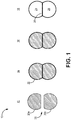
- FIG. 1 is a schematic flow chart of a method of a manufacturing process for making a multi-section tank.
- Method 10 in FIG. 1 shows steps 12 to 18, with soluble tool 20, composite material 22, sections 24, 26, and shared wall 28.
- a soluble tool 20 is prepared.
- Soluble tool 20 has mating parts 20a and 20b, which are each of the desired size and shape corresponding to a finished section of the multi-section tank.
- Mating parts 20a, 20b are made prepared to accept a composite material 22 which will form the multi-section tank, and mating parts 20a, 20b are oriented as such.
- Soluble tool 20 is made of a salt, AquaCore® washout mandrel material, or any comparable material which can later in the process be easily removed.
- an elastomeric layer may be incorporated on the soluble tools 20a and 20b.
- the elastomer expands with heat to create internal pressure to stretch the composite, therefore, reduce the tendency of wrinkle forming in the composite.
- the elastomer can be removed after the composite is cured and soluble tool is washed out.
- step 14 composite material 22 is added around soluble tool mating parts 20a and 20b separately. Then, mating parts 20a and 20b, each enclosed in a first layer of composite material 22, are aligned and joined at the flat surface of 20a and 20b. Afterwards, a second layer of composite material 22 is placed around the joined assembly 20a and 20b.
- the composite material can be, for example, a pre-impregnated matrix having a resin and fibers as is known in the art.
- the resin can be, for example, a polymer such as a thermoplastic or thermoset, or other material appropriate in the art.
- the fiber can be a glass fiber, carbon fiber, or other material as appropriate in the art.
- Composite material can be made of a fabric having a unidirectional weave.
- the composite material 22 can be a stable weave pattern such as plain weave or a twill weave pattern. These tight weaves have a lesser tendency to form wrinkles. In some cases, unidirectional fiber pre-impregnated is used due to the ease of applying tension to it when adding it to the soluble tools, and its reduced tendency to wrinkle.
- a first layer of composite material 22 is wrapped around mating parts 20a and 20b.
- the first layers of composite material 22 Prior to alignment of mating parts 20a and 20b, the first layers of composite material 22 is cured (as described below with reference to step 16). Then, an adhesive is applied to the internal portions of the cured first layer of composite material 22 and the mating parts 20a, 20b are aligned. Additional adhesive is applied to the outer surface of the first layer of composite material 22 to allow for adhesion to a second layer of composite material 22. In this case, the cured first layer of composite material 22 can be checked for wrinkles prior to alignment of mating parts 20a, 20b, and addition of the second layer of composite material.
- composite material 22 Prior to being wrapped around soluble tool 20, composite material 22 is pre-tensioned to tighten the fibers within the composite material 22 and prevent wrinkling forming due to fiber looseness. Pre-tensioning is shown in FIG. 2 . Here, soluble tool mating part 20a is wrapped with composite material 22. Tension is applied to composite material 22 in the direction of arrow T.
- Pre-tensioning can be done by hand or with the assistance of a device fixture.
- the composite material 22 is stretched out with a tension force between 1 and 10 pounds per inch (1.75 to 17.5 Newton per centimeter).
- the tension is applied uniformly across the width of the fabric to prevent fabric weave pattern distortion.
- the amount of stretch applied to the composite material 22 is proportional to the temperature and pressure at which the composite material 22 will later be cured.
- the temperature and pressure at which pre-tensioning is done is also dependent on the expansion and compression on soluble tool 20 during the curing process.
- Pre-tensioned composite material 22 is more difficult to wrinkle and more resistant to folding or crinkling during curing processes.
- additional reinforcing portions of composite material 22 can be added to parts of the structure prone to wrinkling.
- a piece of unidirectional fiber pre-impregnated fabric, or a relatively stiffer fabric (that is, stiffer compared to the primary composite material 22) comprising a resin and fibers analogous to the primary composite material can be applied to local areas prone to wrinkling, such as corners, joints between tank sections, or acute angles.
- These reinforcing portions can be cured with the primary composite material in step 16.
- the composite material 22 is cured around soluble tool 20.
- the composite material 22 cures to the shape of soluble tool 20 mating parts 20a, 20b, and in particular cures to create both external walls defining sections 24, 26 and shared wall 28.
- the composite material 22 can be cured, for example, in an autoclave at a range between 200 and 400 degrees Fahrenheit (93 and 204 degrees Celsius), with pressure between 10 psi (69 kPa) and 100 psi (689 kPa). Generally, the curing process can take between 1 and 3 hours.
- step 18 soluble tool 20 is washed out. This can be done by washing with water or other solvent capable of removing the soluble tool 20 without chemically reacting with composite material 22. Pressure washing and vibrating the tank aid in breaking up and removing soluble tool 20. This results in a multi-section, composite material tank with shared wall 28.
- a pre-tensioned composite layer When a pre-tensioned composite layer is used, fewer wrinkles form.
- the temperature and pressure applied to the assembly cause soluble tool 20 to expand and contract depending on the amount of thermal expansion and compression under pressure.
- the composite material 22 stretches. If composite material 22 has been pre-tensioned, wrinkling is avoided at the stage. If the soluble tool 20 contracts, the composite material folds in and causes wrinkles. However, if the composite material 20 is pre-tensioned as disclosed, the tool contraction may just release some of the tension in the composite and wrinkle are again less likely to form.
- the prevention of wrinkles by design reduces the dependence on operator experience and increase the quality of the final product.
- a method of making a multi-section composite tank includes pre-tensioning a composite material, surrounding the two mating sections of the soluble tool with the pre-tensioned composite material, aligning two mating sections of a soluble tool, curing the pre-tensioned composite material around the soluble tool, and washing out the soluble tool to form a multi-section tank.
- the method of the preceding paragraph can optionally include, additionally and/or alternatively, any one or more of the following features, configurations and/or additional components:
- the soluble tool is salt-based.
- the soluble tool has an elastomeric outer layer.
- the elastomeric outer layer is a thermoplastic or thermoset.
- the composite material is a material having a unidirectional weave.
- the composite material is a pre-impregnated fabric comprising a resin and a fiber.
- the resin is a thermoplastic or a thermoset material.
- the fiber is carbon fiber, carbon nanotube fiber, or glass fiber.
- the composite material is plain weave fabric, wide-spaced woven fabric, twill, or a wave pattern woven fabric.
- the method includes reinforcing the pre-tensioned composite material with a second composite material.
- Reinforcing the pre-tensioned composite material comprises applying the second composite material at joints or corners or the multi-section composite tank.
- Curing the pre-tensioned composite material is done between 200 and 400 degrees Fahrenheit (93 and 204 degrees Celsius).
- Curing the composite material is done at a pressure between 10 psi (69kPa) and 100 psi (689 kPa) for a duration between 5 minutes and 4 hours.
- Pre-tensioning the composite material comprises applying a force of up to one to ten pound per inch (1.75 to 17.5 Newtons per centimeter) of material.
- Pre-tensioning the composite material comprises stretching the composite material by hand or by machine.
- Pre-tensioning the composite material comprises aligning fibers in the composite material.
- Pre-tensioning the composite material comprises applying substantially uniform tension across the applied width of the composite material.
- the method includes applying a second layer of the composite material to the aligned mating sections of the soluble tool.
- the method includes further comprising curing the first layer of the composite material prior to adding the second layer of the composite material.
- the method includes further comprising joining the second layer of composite material to the first layer of composite material with an adhesive.
Landscapes
- Engineering & Computer Science (AREA)
- Mechanical Engineering (AREA)
- Chemical & Material Sciences (AREA)
- Composite Materials (AREA)
- Moulding By Coating Moulds (AREA)
Abstract
Description
- The present disclosure relates to multi-section composite tanks. More specifically, the present disclosure relates to composite, high-pressure multi-section tanks for use in aircraft potable water systems.
- Aircraft potable water systems supply drinkable water throughout an aircraft for various uses. Aircraft potable water systems typically include many parts, including but not limited to: multi-section tanks, hydraulic pumps, fluid heaters, control valves, and hydraulic fluid line tubing. The multi-section tanks used for aircraft potable water vessels are generally pressurized and must maintain their shape while under internal pressure.
- Pressurized tanks for aircraft potable water systems generally contain multiple sections. Conventionally, metallic sheets are welded in the multi-section tanks.
- The tank sections can also be made of a lightweight composite materials. Multiple plies of composite materials are first put together and then cured into the multi-section tank. Often, when the uncured composite material is placed to create the multi-section tank sections, wrinkles arise in the placement or layup process. In particular, the plies of the composite material can be bunched together into one area, causing a wrinkle.
- These wrinkles are amplified when the whole multi-section tank is subsequently cured in high pressure conditions, such as in an autoclave. Additional wrinkles can form during this process. In cases where the vessel is of complex geometry, there is a higher probability of wrinkles forming. Wrinkled or uneven material is, in general, less strong than straight material. This causes uneven mechanical stresses throughout the vessel sections when the vessel is pressurized internally.
- In one embodiment, a method of making a multi-section composite tank includes pre-tensioning a composite material, surrounding the two mating sections of the soluble tool with the pre-tensioned composite material, aligning two mating sections of a soluble tool, curing the pre-tensioned composite material around the soluble tool, and washing out the soluble tool to form a multi-section tank.
-
-
FIG. 1 is a schematic flow chart of a method of a build process for making a multiple-section tank. -
FIG. 2 is a schematic drawings showing pre-tensioning of a composite material for building a multi-section tank. - When multi-section tanks are made through the process described in reference to
FIG. 1 , the composite material defining the sections of the vessel are prone to wrinkle formation in high temperature and pressure curing processes. Pre-tensioning of the composite material and material selection can prevent wrinkling and provide consistent final products, which is frequently a desirable result. -
FIG. 1 is a schematic flow chart of a method of a manufacturing process for making a multi-section tank.Method 10 inFIG. 1 showssteps 12 to 18, withsoluble tool 20,composite material 22,sections wall 28. - First, in
step 12, asoluble tool 20 is prepared.Soluble tool 20 hasmating parts Mating parts composite material 22 which will form the multi-section tank, andmating parts Soluble tool 20 is made of a salt, AquaCore® washout mandrel material, or any comparable material which can later in the process be easily removed. - Optionally, an elastomeric layer may be incorporated on the
soluble tools - Next, in
step 14,composite material 22 is added around solubletool mating parts mating parts composite material 22, are aligned and joined at the flat surface of 20a and 20b. Afterwards, a second layer ofcomposite material 22 is placed around the joinedassembly composite material 22 can be a stable weave pattern such as plain weave or a twill weave pattern. These tight weaves have a lesser tendency to form wrinkles. In some cases, unidirectional fiber pre-impregnated is used due to the ease of applying tension to it when adding it to the soluble tools, and its reduced tendency to wrinkle. - In some cases, a first layer of
composite material 22 is wrapped aroundmating parts mating parts composite material 22 is cured (as described below with reference to step 16). Then, an adhesive is applied to the internal portions of the cured first layer ofcomposite material 22 and themating parts composite material 22 to allow for adhesion to a second layer ofcomposite material 22. In this case, the cured first layer ofcomposite material 22 can be checked for wrinkles prior to alignment ofmating parts - Prior to being wrapped around
soluble tool 20,composite material 22 is pre-tensioned to tighten the fibers within thecomposite material 22 and prevent wrinkling forming due to fiber looseness. Pre-tensioning is shown inFIG. 2 . Here, solubletool mating part 20a is wrapped withcomposite material 22. Tension is applied tocomposite material 22 in the direction of arrow T. - Pre-tensioning can be done by hand or with the assistance of a device fixture. During pre-tensioning, the
composite material 22 is stretched out with a tension force between 1 and 10 pounds per inch (1.75 to 17.5 Newton per centimeter). The tension is applied uniformly across the width of the fabric to prevent fabric weave pattern distortion. The amount of stretch applied to thecomposite material 22 is proportional to the temperature and pressure at which thecomposite material 22 will later be cured. The temperature and pressure at which pre-tensioning is done is also dependent on the expansion and compression onsoluble tool 20 during the curing process. Pre-tensionedcomposite material 22 is more difficult to wrinkle and more resistant to folding or crinkling during curing processes. - Optionally, additional reinforcing portions of
composite material 22 can be added to parts of the structure prone to wrinkling. In these areas, a piece of unidirectional fiber pre-impregnated fabric, or a relatively stiffer fabric (that is, stiffer compared to the primary composite material 22) comprising a resin and fibers analogous to the primary composite material can be applied to local areas prone to wrinkling, such as corners, joints between tank sections, or acute angles. These reinforcing portions can be cured with the primary composite material instep 16. - In
step 16, thecomposite material 22 is cured aroundsoluble tool 20. Thecomposite material 22 cures to the shape ofsoluble tool 20mating parts walls defining sections wall 28. Thecomposite material 22 can be cured, for example, in an autoclave at a range between 200 and 400 degrees Fahrenheit (93 and 204 degrees Celsius), with pressure between 10 psi (69 kPa) and 100 psi (689 kPa). Generally, the curing process can take between 1 and 3 hours. - Finally, in
step 18,soluble tool 20 is washed out. This can be done by washing with water or other solvent capable of removing thesoluble tool 20 without chemically reacting withcomposite material 22. Pressure washing and vibrating the tank aid in breaking up and removingsoluble tool 20. This results in a multi-section, composite material tank with sharedwall 28. - When a pre-tensioned composite layer is used, fewer wrinkles form. During the curing process, the temperature and pressure applied to the assembly cause
soluble tool 20 to expand and contract depending on the amount of thermal expansion and compression under pressure. When thesoluble tool 20 expands, thecomposite material 22 stretches. Ifcomposite material 22 has been pre-tensioned, wrinkling is avoided at the stage. If thesoluble tool 20 contracts, the composite material folds in and causes wrinkles. However, if thecomposite material 20 is pre-tensioned as disclosed, the tool contraction may just release some of the tension in the composite and wrinkle are again less likely to form. The prevention of wrinkles by design reduces the dependence on operator experience and increase the quality of the final product. - The following are non-exclusive descriptions of possible embodiments of the present invention.
- A method of making a multi-section composite tank includes pre-tensioning a composite material, surrounding the two mating sections of the soluble tool with the pre-tensioned composite material, aligning two mating sections of a soluble tool, curing the pre-tensioned composite material around the soluble tool, and washing out the soluble tool to form a multi-section tank.
- The method of the preceding paragraph can optionally include, additionally and/or alternatively, any one or more of the following features, configurations and/or additional components:
The soluble tool is salt-based. - The soluble tool has an elastomeric outer layer.
- The elastomeric outer layer is a thermoplastic or thermoset.
- The composite material is a material having a unidirectional weave.
- The composite material is a pre-impregnated fabric comprising a resin and a fiber.
- The resin is a thermoplastic or a thermoset material.
- The fiber is carbon fiber, carbon nanotube fiber, or glass fiber.
- The composite material is plain weave fabric, wide-spaced woven fabric, twill, or a wave pattern woven fabric.
- The method includes reinforcing the pre-tensioned composite material with a second composite material.
- Reinforcing the pre-tensioned composite material comprises applying the second composite material at joints or corners or the multi-section composite tank.
- Curing the pre-tensioned composite material is done between 200 and 400 degrees Fahrenheit (93 and 204 degrees Celsius).
- Curing the composite material is done at a pressure between 10 psi (69kPa) and 100 psi (689 kPa) for a duration between 5 minutes and 4 hours.
- Pre-tensioning the composite material comprises applying a force of up to one to ten pound per inch (1.75 to 17.5 Newtons per centimeter) of material.
- Pre-tensioning the composite material comprises stretching the composite material by hand or by machine.
- Pre-tensioning the composite material comprises aligning fibers in the composite material.
- Pre-tensioning the composite material comprises applying substantially uniform tension across the applied width of the composite material.
- The method includes applying a second layer of the composite material to the aligned mating sections of the soluble tool.
- The method includes further comprising curing the first layer of the composite material prior to adding the second layer of the composite material.
- The method includes further comprising joining the second layer of composite material to the first layer of composite material with an adhesive.
- While the invention has been described with reference to an exemplary embodiment(s), it will be understood by those skilled in the art that various changes may be made and equivalents may be substituted for elements thereof without departing from the scope of the invention as defined by the claims. In addition, many modifications may be made to adapt a particular situation or material to the teachings of the invention without departing from the scope thereof. Therefore, it is intended that the invention not be limited to the particular embodiment(s) disclosed, but that the invention will include all embodiments falling within the scope of the appended claims.
Claims (15)
- A method of making a multi-section composite tank comprising:pre-tensioning a composite material (22);surrounding two mating sections (20a, 20b) of a soluble tool (20) with the pre-tensioned composite material;aligning the two mating sections of the soluble tool;curing the pre-tensioned composite material around the soluble tool; andwashing out the soluble tool to form a multi-section tank.
- The method of claim 1, wherein the soluble tool is salt-based.
- The method of claim 1 or 2, wherein the soluble tool has an elastomeric outer layer and optionally wherein the elastomeric outer layer is a thermoplastic or thermoset.
- The method of any preceding claim, wherein the composite material is a unidirectional fiber material.
- The method of any preceding claim, wherein the composite material is a pre-impregnated fabric comprising a resin and a fiber, and optionally wherein the resin is a thermoplastic or a thermoset material and optionally/or wherein the fiber is carbon fiber, carbon nanotube fiber, Kevlar fiber, or glass fiber.
- The method of any of claims 1 to 3, wherein the composite material is plain weave fabric, twill weave fabric, or other stable-pattern fabric.
- The method of any preceding claim, further comprising locally reinforcing the pre-tensioned composite material with a second composite material.
- The method of claim 7, wherein reinforcing the pre-tensioned composite material comprises applying the second composite material at joints or corners of the multi-section composite tank.
- The method of any preceding claim, wherein curing the pre-tensioned composite material is done between 200 and 400 degrees Fahrenheit (93 and 204 degrees Celsius).
- The method of any preceding claim, wherein curing the composite material is done at a pressure between 10 psi (69kPa) and 100 psi (689 kPa) for a duration between 5 minutes and 4 hours.
- The method of any preceding claim, wherein pre-tensioning the composite material comprises applying a force of 1 to 10 pounds per inch (1.75 to 17.5 Newton per centimeter) of material.
- The method of any preceding claim, wherein pre-tensioning the composite material comprises stretching the composite material by hand or by machine.
- The method of any of claims 1 to 11, wherein pre-tensioning the composite material comprises tightening fibers in the composite material.
- The method of any preceding claim, wherein pre-tensioning the composite material comprises applying substantially uniform tension across the applied width of the composite material.
- The method of any preceding claim, further comprising applying a second layer of the composite material to the aligned mating sections of the soluble tool, and optionally further comprising curing the first layer of the composite material prior to adding the second layer of the composite material, and optionally further comprising joining the second layer of composite material to the first layer of composite material with an adhesive.
Applications Claiming Priority (2)
| Application Number | Priority Date | Filing Date | Title |
|---|---|---|---|
| US201962789307P | 2019-01-07 | 2019-01-07 | |
| US16/682,131 US11220074B2 (en) | 2019-01-07 | 2019-11-13 | Reduced wrinkles in multi-section composite tank |
Publications (2)
| Publication Number | Publication Date |
|---|---|
| EP3677409A1 true EP3677409A1 (en) | 2020-07-08 |
| EP3677409B1 EP3677409B1 (en) | 2023-04-12 |
Family
ID=68766572
Family Applications (1)
| Application Number | Title | Priority Date | Filing Date |
|---|---|---|---|
| EP19213102.7A Active EP3677409B1 (en) | 2019-01-07 | 2019-12-03 | Reduced wrinkles in multi-section composite tank |
Country Status (4)
| Country | Link |
|---|---|
| US (1) | US11220074B2 (en) |
| EP (1) | EP3677409B1 (en) |
| CN (1) | CN111409288A (en) |
| CA (1) | CA3063054A1 (en) |
Citations (5)
| Publication number | Priority date | Publication date | Assignee | Title |
|---|---|---|---|---|
| US3357875A (en) * | 1963-01-21 | 1967-12-12 | Jr George T Corbin | Multi-part hollow casting |
| US3508677A (en) * | 1968-08-20 | 1970-04-28 | Whittaker Corp | Vessel for storing high-pressure gases |
| EP0124205A1 (en) * | 1983-04-21 | 1984-11-07 | Lear Siegler Energy Products Corporation | Containment vessel and method of manufacturing same |
| US5798156A (en) * | 1996-06-03 | 1998-08-25 | Mitlitsky; Fred | Lightweight bladder lined pressure vessels |
| WO2017184171A1 (en) * | 2016-04-22 | 2017-10-26 | Utrc-Ibd | A method of manufacturing a composite vessel assembly |
Family Cites Families (15)
| Publication number | Priority date | Publication date | Assignee | Title |
|---|---|---|---|---|
| US3210228A (en) * | 1961-07-06 | 1965-10-05 | Trw Inc | Method and apparatus for making a filament wound pressure vessel |
| US3549444A (en) * | 1967-12-28 | 1970-12-22 | Harry S Katz | Filament wound blade and compressor |
| US7249943B2 (en) | 2003-08-01 | 2007-07-31 | Alliant Techsystems Inc. | Apparatus for forming composite stiffeners and reinforcing structures |
| US7588655B2 (en) | 2004-11-24 | 2009-09-15 | The Boeing Company | Mandrel with differential in thermal expansion to eliminate wrinkles in ply |
| US8557165B2 (en) | 2008-10-25 | 2013-10-15 | The Boeing Company | Forming highly contoured composite parts |
| US8632653B2 (en) | 2005-05-03 | 2014-01-21 | The Boeing Company | Method of manufacturing curved composite structural elements |
| US9327467B2 (en) | 2008-07-10 | 2016-05-03 | The Boeing Company | Composite mandrel for autoclave curing applications |
| US8795567B2 (en) | 2010-09-23 | 2014-08-05 | The Boeing Company | Method for fabricating highly contoured composite stiffeners with reduced wrinkling |
| AP2015008576A0 (en) * | 2012-12-05 | 2015-07-31 | Blue Wave Co Sa | Pressure vessel with high tension winding to reduce fatigue |
| US9205625B2 (en) | 2013-02-19 | 2015-12-08 | The Boeing Company | Spiral laminated structural cone and manufacturing method |
| US9120255B2 (en) * | 2013-03-15 | 2015-09-01 | Bell Helicopter Textron Inc. | Composite core and method of making same |
| GB2524007B (en) | 2014-03-10 | 2016-02-24 | Gkn Aerospace Services Ltd | Method of designing and manufacturing a composite component |
| US11046049B2 (en) | 2014-03-19 | 2021-06-29 | The Boeing Company | Fabrication of composite laminates using temporarily stitched preforms |
| ES2731210T3 (en) | 2014-09-26 | 2019-11-14 | Airbus Operations Sl | Method for manufacturing a piece of composite material comprising a core and at least one flange |
| WO2017184170A1 (en) * | 2016-04-22 | 2017-10-26 | Utrc-Ibd | Composite pressure vessel assembly with an integrated nozzle assembly |
-
2019
- 2019-11-13 US US16/682,131 patent/US11220074B2/en active Active
- 2019-11-26 CA CA3063054A patent/CA3063054A1/en active Pending
- 2019-12-03 EP EP19213102.7A patent/EP3677409B1/en active Active
- 2019-12-13 CN CN201911284195.6A patent/CN111409288A/en active Pending
Patent Citations (5)
| Publication number | Priority date | Publication date | Assignee | Title |
|---|---|---|---|---|
| US3357875A (en) * | 1963-01-21 | 1967-12-12 | Jr George T Corbin | Multi-part hollow casting |
| US3508677A (en) * | 1968-08-20 | 1970-04-28 | Whittaker Corp | Vessel for storing high-pressure gases |
| EP0124205A1 (en) * | 1983-04-21 | 1984-11-07 | Lear Siegler Energy Products Corporation | Containment vessel and method of manufacturing same |
| US5798156A (en) * | 1996-06-03 | 1998-08-25 | Mitlitsky; Fred | Lightweight bladder lined pressure vessels |
| WO2017184171A1 (en) * | 2016-04-22 | 2017-10-26 | Utrc-Ibd | A method of manufacturing a composite vessel assembly |
Also Published As
| Publication number | Publication date |
|---|---|
| US20200215772A1 (en) | 2020-07-09 |
| EP3677409B1 (en) | 2023-04-12 |
| US11220074B2 (en) | 2022-01-11 |
| CA3063054A1 (en) | 2020-07-07 |
| CN111409288A (en) | 2020-07-14 |
Similar Documents
| Publication | Publication Date | Title |
|---|---|---|
| EP3162544B1 (en) | Method and device for producing contoured composite laminate stiffeners with reduced wrinkling | |
| JP6262842B2 (en) | Method and apparatus for reducing layer wrinkles in a composite laminate during molding | |
| JP5424891B2 (en) | Apparatus and method for forming a hat-reinforced composite part using a thermal expansion tooling call | |
| US5145621A (en) | Crossover mold tool for consolidating composite material | |
| EP2116358B1 (en) | Method and apparatus for conforming a blank | |
| US7824171B2 (en) | Corner-consolidating inflatable apparatus and method for manufacturing composite structures | |
| US20160339682A1 (en) | Bladder System for Curing Composite Parts | |
| EP2371523A1 (en) | A method and a device for repairing parts of composite material of an aircraft | |
| CN106414031B (en) | Apparatus and method for forming a flange | |
| JP2011235635A (en) | Collapsible mandrel employing reinforced fluoroelastomeric bladder | |
| US20100206994A1 (en) | Composite structure and related method to obtain it | |
| KR20120091168A (en) | Woven preform, composite, and method of making thereof | |
| JP7216527B2 (en) | Method and apparatus for forming a radius filler kit | |
| US9862122B2 (en) | Reinforced bladder | |
| US9114600B2 (en) | Method for creating a vacuum setup for producing a fiber composite part, and plunger used in the method | |
| EP4023422B1 (en) | Method for manufacturing structure and structure | |
| WO2016133393A1 (en) | Thermosetting composite article and method for producing the same | |
| JP2008006814A (en) | Preform manufacturing method, preform, and fiber reinforced plastic girder | |
| US11220074B2 (en) | Reduced wrinkles in multi-section composite tank | |
| US20110100538A1 (en) | Method of manufacturing a fuselage frame of composite material | |
| CA2926962A1 (en) | Apparatuses and methods for making reinforcement structures | |
| CN111683804A (en) | Method for molding tubular composite structures | |
| CN116423858B (en) | A method for preparing a water pressure bag in a conveyor belt joint vulcanizing machine | |
| US11285655B2 (en) | Method of manufacturing a plastic tank | |
| JP5374304B2 (en) | Fiber reinforced resin cheese molding method |
Legal Events
| Date | Code | Title | Description |
|---|---|---|---|
| PUAI | Public reference made under article 153(3) epc to a published international application that has entered the european phase |
Free format text: ORIGINAL CODE: 0009012 |
|
| STAA | Information on the status of an ep patent application or granted ep patent |
Free format text: STATUS: THE APPLICATION HAS BEEN PUBLISHED |
|
| AK | Designated contracting states |
Kind code of ref document: A1 Designated state(s): AL AT BE BG CH CY CZ DE DK EE ES FI FR GB GR HR HU IE IS IT LI LT LU LV MC MK MT NL NO PL PT RO RS SE SI SK SM TR |
|
| AX | Request for extension of the european patent |
Extension state: BA ME |
|
| STAA | Information on the status of an ep patent application or granted ep patent |
Free format text: STATUS: REQUEST FOR EXAMINATION WAS MADE |
|
| 17P | Request for examination filed |
Effective date: 20210108 |
|
| RBV | Designated contracting states (corrected) |
Designated state(s): AL AT BE BG CH CY CZ DE DK EE ES FI FR GB GR HR HU IE IS IT LI LT LU LV MC MK MT NL NO PL PT RO RS SE SI SK SM TR |
|
| RIC1 | Information provided on ipc code assigned before grant |
Ipc: B29L 31/00 20060101ALN20221003BHEP Ipc: B29C 33/56 20060101ALI20221003BHEP Ipc: B29C 33/52 20060101ALI20221003BHEP Ipc: B29C 70/86 20060101ALI20221003BHEP Ipc: B29C 70/30 20060101AFI20221003BHEP |
|
| GRAP | Despatch of communication of intention to grant a patent |
Free format text: ORIGINAL CODE: EPIDOSNIGR1 |
|
| STAA | Information on the status of an ep patent application or granted ep patent |
Free format text: STATUS: GRANT OF PATENT IS INTENDED |
|
| RIC1 | Information provided on ipc code assigned before grant |
Ipc: B29L 31/00 20060101ALN20221102BHEP Ipc: B29C 33/56 20060101ALI20221102BHEP Ipc: B29C 33/52 20060101ALI20221102BHEP Ipc: B29C 70/86 20060101ALI20221102BHEP Ipc: B29C 70/30 20060101AFI20221102BHEP |
|
| RIC1 | Information provided on ipc code assigned before grant |
Ipc: B29L 31/00 20060101ALN20221117BHEP Ipc: B29C 33/56 20060101ALI20221117BHEP Ipc: B29C 33/52 20060101ALI20221117BHEP Ipc: B29C 70/86 20060101ALI20221117BHEP Ipc: B29C 70/30 20060101AFI20221117BHEP |
|
| INTG | Intention to grant announced |
Effective date: 20221201 |
|
| RIC1 | Information provided on ipc code assigned before grant |
Ipc: B29L 31/00 20060101ALN20221123BHEP Ipc: B29C 33/56 20060101ALI20221123BHEP Ipc: B29C 33/52 20060101ALI20221123BHEP Ipc: B29C 70/86 20060101ALI20221123BHEP Ipc: B29C 70/30 20060101AFI20221123BHEP |
|
| RIN1 | Information on inventor provided before grant (corrected) |
Inventor name: HU, JIN Inventor name: ZHAO, WENPING Inventor name: CHING, NATHANIEL |
|
| GRAS | Grant fee paid |
Free format text: ORIGINAL CODE: EPIDOSNIGR3 |
|
| GRAA | (expected) grant |
Free format text: ORIGINAL CODE: 0009210 |
|
| STAA | Information on the status of an ep patent application or granted ep patent |
Free format text: STATUS: THE PATENT HAS BEEN GRANTED |
|
| AK | Designated contracting states |
Kind code of ref document: B1 Designated state(s): AL AT BE BG CH CY CZ DE DK EE ES FI FR GB GR HR HU IE IS IT LI LT LU LV MC MK MT NL NO PL PT RO RS SE SI SK SM TR |
|
| REG | Reference to a national code |
Ref country code: GB Ref legal event code: FG4D |
|
| REG | Reference to a national code |
Ref country code: CH Ref legal event code: EP |
|
| REG | Reference to a national code |
Ref country code: DE Ref legal event code: R096 Ref document number: 602019027425 Country of ref document: DE |
|
| REG | Reference to a national code |
Ref country code: IE Ref legal event code: FG4D |
|
| REG | Reference to a national code |
Ref country code: AT Ref legal event code: REF Ref document number: 1559535 Country of ref document: AT Kind code of ref document: T Effective date: 20230515 |
|
| P01 | Opt-out of the competence of the unified patent court (upc) registered |
Effective date: 20230521 |
|
| REG | Reference to a national code |
Ref country code: LT Ref legal event code: MG9D |
|
| REG | Reference to a national code |
Ref country code: NL Ref legal event code: MP Effective date: 20230412 |
|
| REG | Reference to a national code |
Ref country code: AT Ref legal event code: MK05 Ref document number: 1559535 Country of ref document: AT Kind code of ref document: T Effective date: 20230412 |
|
| PG25 | Lapsed in a contracting state [announced via postgrant information from national office to epo] |
Ref country code: NL Free format text: LAPSE BECAUSE OF FAILURE TO SUBMIT A TRANSLATION OF THE DESCRIPTION OR TO PAY THE FEE WITHIN THE PRESCRIBED TIME-LIMIT Effective date: 20230412 |
|
| PG25 | Lapsed in a contracting state [announced via postgrant information from national office to epo] |
Ref country code: SE Free format text: LAPSE BECAUSE OF FAILURE TO SUBMIT A TRANSLATION OF THE DESCRIPTION OR TO PAY THE FEE WITHIN THE PRESCRIBED TIME-LIMIT Effective date: 20230412 Ref country code: PT Free format text: LAPSE BECAUSE OF FAILURE TO SUBMIT A TRANSLATION OF THE DESCRIPTION OR TO PAY THE FEE WITHIN THE PRESCRIBED TIME-LIMIT Effective date: 20230814 Ref country code: NO Free format text: LAPSE BECAUSE OF FAILURE TO SUBMIT A TRANSLATION OF THE DESCRIPTION OR TO PAY THE FEE WITHIN THE PRESCRIBED TIME-LIMIT Effective date: 20230712 Ref country code: ES Free format text: LAPSE BECAUSE OF FAILURE TO SUBMIT A TRANSLATION OF THE DESCRIPTION OR TO PAY THE FEE WITHIN THE PRESCRIBED TIME-LIMIT Effective date: 20230412 Ref country code: AT Free format text: LAPSE BECAUSE OF FAILURE TO SUBMIT A TRANSLATION OF THE DESCRIPTION OR TO PAY THE FEE WITHIN THE PRESCRIBED TIME-LIMIT Effective date: 20230412 |
|
| PG25 | Lapsed in a contracting state [announced via postgrant information from national office to epo] |
Ref country code: RS Free format text: LAPSE BECAUSE OF FAILURE TO SUBMIT A TRANSLATION OF THE DESCRIPTION OR TO PAY THE FEE WITHIN THE PRESCRIBED TIME-LIMIT Effective date: 20230412 Ref country code: PL Free format text: LAPSE BECAUSE OF FAILURE TO SUBMIT A TRANSLATION OF THE DESCRIPTION OR TO PAY THE FEE WITHIN THE PRESCRIBED TIME-LIMIT Effective date: 20230412 Ref country code: LV Free format text: LAPSE BECAUSE OF FAILURE TO SUBMIT A TRANSLATION OF THE DESCRIPTION OR TO PAY THE FEE WITHIN THE PRESCRIBED TIME-LIMIT Effective date: 20230412 Ref country code: LT Free format text: LAPSE BECAUSE OF FAILURE TO SUBMIT A TRANSLATION OF THE DESCRIPTION OR TO PAY THE FEE WITHIN THE PRESCRIBED TIME-LIMIT Effective date: 20230412 Ref country code: IS Free format text: LAPSE BECAUSE OF FAILURE TO SUBMIT A TRANSLATION OF THE DESCRIPTION OR TO PAY THE FEE WITHIN THE PRESCRIBED TIME-LIMIT Effective date: 20230812 Ref country code: HR Free format text: LAPSE BECAUSE OF FAILURE TO SUBMIT A TRANSLATION OF THE DESCRIPTION OR TO PAY THE FEE WITHIN THE PRESCRIBED TIME-LIMIT Effective date: 20230412 Ref country code: GR Free format text: LAPSE BECAUSE OF FAILURE TO SUBMIT A TRANSLATION OF THE DESCRIPTION OR TO PAY THE FEE WITHIN THE PRESCRIBED TIME-LIMIT Effective date: 20230713 Ref country code: AL Free format text: LAPSE BECAUSE OF FAILURE TO SUBMIT A TRANSLATION OF THE DESCRIPTION OR TO PAY THE FEE WITHIN THE PRESCRIBED TIME-LIMIT Effective date: 20230412 |
|
| PG25 | Lapsed in a contracting state [announced via postgrant information from national office to epo] |
Ref country code: FI Free format text: LAPSE BECAUSE OF FAILURE TO SUBMIT A TRANSLATION OF THE DESCRIPTION OR TO PAY THE FEE WITHIN THE PRESCRIBED TIME-LIMIT Effective date: 20230412 |
|
| REG | Reference to a national code |
Ref country code: DE Ref legal event code: R097 Ref document number: 602019027425 Country of ref document: DE |
|
| PG25 | Lapsed in a contracting state [announced via postgrant information from national office to epo] |
Ref country code: SK Free format text: LAPSE BECAUSE OF FAILURE TO SUBMIT A TRANSLATION OF THE DESCRIPTION OR TO PAY THE FEE WITHIN THE PRESCRIBED TIME-LIMIT Effective date: 20230412 |
|
| PG25 | Lapsed in a contracting state [announced via postgrant information from national office to epo] |
Ref country code: SM Free format text: LAPSE BECAUSE OF FAILURE TO SUBMIT A TRANSLATION OF THE DESCRIPTION OR TO PAY THE FEE WITHIN THE PRESCRIBED TIME-LIMIT Effective date: 20230412 Ref country code: SK Free format text: LAPSE BECAUSE OF FAILURE TO SUBMIT A TRANSLATION OF THE DESCRIPTION OR TO PAY THE FEE WITHIN THE PRESCRIBED TIME-LIMIT Effective date: 20230412 Ref country code: RO Free format text: LAPSE BECAUSE OF FAILURE TO SUBMIT A TRANSLATION OF THE DESCRIPTION OR TO PAY THE FEE WITHIN THE PRESCRIBED TIME-LIMIT Effective date: 20230412 Ref country code: EE Free format text: LAPSE BECAUSE OF FAILURE TO SUBMIT A TRANSLATION OF THE DESCRIPTION OR TO PAY THE FEE WITHIN THE PRESCRIBED TIME-LIMIT Effective date: 20230412 Ref country code: DK Free format text: LAPSE BECAUSE OF FAILURE TO SUBMIT A TRANSLATION OF THE DESCRIPTION OR TO PAY THE FEE WITHIN THE PRESCRIBED TIME-LIMIT Effective date: 20230412 Ref country code: CZ Free format text: LAPSE BECAUSE OF FAILURE TO SUBMIT A TRANSLATION OF THE DESCRIPTION OR TO PAY THE FEE WITHIN THE PRESCRIBED TIME-LIMIT Effective date: 20230412 |
|
| PLBE | No opposition filed within time limit |
Free format text: ORIGINAL CODE: 0009261 |
|
| STAA | Information on the status of an ep patent application or granted ep patent |
Free format text: STATUS: NO OPPOSITION FILED WITHIN TIME LIMIT |
|
| 26N | No opposition filed |
Effective date: 20240115 |
|
| PG25 | Lapsed in a contracting state [announced via postgrant information from national office to epo] |
Ref country code: SI Free format text: LAPSE BECAUSE OF FAILURE TO SUBMIT A TRANSLATION OF THE DESCRIPTION OR TO PAY THE FEE WITHIN THE PRESCRIBED TIME-LIMIT Effective date: 20230412 |
|
| PG25 | Lapsed in a contracting state [announced via postgrant information from national office to epo] |
Ref country code: SI Free format text: LAPSE BECAUSE OF FAILURE TO SUBMIT A TRANSLATION OF THE DESCRIPTION OR TO PAY THE FEE WITHIN THE PRESCRIBED TIME-LIMIT Effective date: 20230412 Ref country code: IT Free format text: LAPSE BECAUSE OF FAILURE TO SUBMIT A TRANSLATION OF THE DESCRIPTION OR TO PAY THE FEE WITHIN THE PRESCRIBED TIME-LIMIT Effective date: 20230412 |
|
| REG | Reference to a national code |
Ref country code: CH Ref legal event code: PL |
|
| PG25 | Lapsed in a contracting state [announced via postgrant information from national office to epo] |
Ref country code: LU Free format text: LAPSE BECAUSE OF NON-PAYMENT OF DUE FEES Effective date: 20231203 |
|
| PG25 | Lapsed in a contracting state [announced via postgrant information from national office to epo] |
Ref country code: MC Free format text: LAPSE BECAUSE OF FAILURE TO SUBMIT A TRANSLATION OF THE DESCRIPTION OR TO PAY THE FEE WITHIN THE PRESCRIBED TIME-LIMIT Effective date: 20230412 |
|
| REG | Reference to a national code |
Ref country code: BE Ref legal event code: MM Effective date: 20231231 |
|
| PG25 | Lapsed in a contracting state [announced via postgrant information from national office to epo] |
Ref country code: MC Free format text: LAPSE BECAUSE OF FAILURE TO SUBMIT A TRANSLATION OF THE DESCRIPTION OR TO PAY THE FEE WITHIN THE PRESCRIBED TIME-LIMIT Effective date: 20230412 Ref country code: LU Free format text: LAPSE BECAUSE OF NON-PAYMENT OF DUE FEES Effective date: 20231203 |
|
| REG | Reference to a national code |
Ref country code: IE Ref legal event code: MM4A |
|
| PG25 | Lapsed in a contracting state [announced via postgrant information from national office to epo] |
Ref country code: IE Free format text: LAPSE BECAUSE OF NON-PAYMENT OF DUE FEES Effective date: 20231203 |
|
| PG25 | Lapsed in a contracting state [announced via postgrant information from national office to epo] |
Ref country code: BE Free format text: LAPSE BECAUSE OF NON-PAYMENT OF DUE FEES Effective date: 20231231 |
|
| PG25 | Lapsed in a contracting state [announced via postgrant information from national office to epo] |
Ref country code: CH Free format text: LAPSE BECAUSE OF NON-PAYMENT OF DUE FEES Effective date: 20231231 |
|
| PG25 | Lapsed in a contracting state [announced via postgrant information from national office to epo] |
Ref country code: IE Free format text: LAPSE BECAUSE OF NON-PAYMENT OF DUE FEES Effective date: 20231203 Ref country code: CH Free format text: LAPSE BECAUSE OF NON-PAYMENT OF DUE FEES Effective date: 20231231 Ref country code: BE Free format text: LAPSE BECAUSE OF NON-PAYMENT OF DUE FEES Effective date: 20231231 |
|
| PG25 | Lapsed in a contracting state [announced via postgrant information from national office to epo] |
Ref country code: BG Free format text: LAPSE BECAUSE OF FAILURE TO SUBMIT A TRANSLATION OF THE DESCRIPTION OR TO PAY THE FEE WITHIN THE PRESCRIBED TIME-LIMIT Effective date: 20230412 |
|
| PG25 | Lapsed in a contracting state [announced via postgrant information from national office to epo] |
Ref country code: BG Free format text: LAPSE BECAUSE OF FAILURE TO SUBMIT A TRANSLATION OF THE DESCRIPTION OR TO PAY THE FEE WITHIN THE PRESCRIBED TIME-LIMIT Effective date: 20230412 |
|
| PG25 | Lapsed in a contracting state [announced via postgrant information from national office to epo] |
Ref country code: CY Free format text: LAPSE BECAUSE OF FAILURE TO SUBMIT A TRANSLATION OF THE DESCRIPTION OR TO PAY THE FEE WITHIN THE PRESCRIBED TIME-LIMIT; INVALID AB INITIO Effective date: 20191203 |
|
| PG25 | Lapsed in a contracting state [announced via postgrant information from national office to epo] |
Ref country code: HU Free format text: LAPSE BECAUSE OF FAILURE TO SUBMIT A TRANSLATION OF THE DESCRIPTION OR TO PAY THE FEE WITHIN THE PRESCRIBED TIME-LIMIT; INVALID AB INITIO Effective date: 20191203 |
|
| PG25 | Lapsed in a contracting state [announced via postgrant information from national office to epo] |
Ref country code: TR Free format text: LAPSE BECAUSE OF FAILURE TO SUBMIT A TRANSLATION OF THE DESCRIPTION OR TO PAY THE FEE WITHIN THE PRESCRIBED TIME-LIMIT Effective date: 20230412 |
|
| PGFP | Annual fee paid to national office [announced via postgrant information from national office to epo] |
Ref country code: DE Payment date: 20251126 Year of fee payment: 7 |
|
| PGFP | Annual fee paid to national office [announced via postgrant information from national office to epo] |
Ref country code: GB Payment date: 20251119 Year of fee payment: 7 |
|
| PGFP | Annual fee paid to national office [announced via postgrant information from national office to epo] |
Ref country code: FR Payment date: 20251120 Year of fee payment: 7 |