EP3677344A1 - Viscous material stirring device and viscous material stirring method - Google Patents
Viscous material stirring device and viscous material stirring method Download PDFInfo
- Publication number
- EP3677344A1 EP3677344A1 EP18850158.9A EP18850158A EP3677344A1 EP 3677344 A1 EP3677344 A1 EP 3677344A1 EP 18850158 A EP18850158 A EP 18850158A EP 3677344 A1 EP3677344 A1 EP 3677344A1
- Authority
- EP
- European Patent Office
- Prior art keywords
- viscous material
- stirring
- stirring member
- rotation axis
- tip
- Prior art date
- Legal status (The legal status is an assumption and is not a legal conclusion. Google has not performed a legal analysis and makes no representation as to the accuracy of the status listed.)
- Granted
Links
Images



Classifications
-
- B—PERFORMING OPERATIONS; TRANSPORTING
- B01—PHYSICAL OR CHEMICAL PROCESSES OR APPARATUS IN GENERAL
- B01F—MIXING, e.g. DISSOLVING, EMULSIFYING OR DISPERSING
- B01F35/00—Accessories for mixers; Auxiliary operations or auxiliary devices; Parts or details of general application
- B01F35/30—Driving arrangements; Transmissions; Couplings; Brakes
- B01F35/32—Driving arrangements
- B01F35/32005—Type of drive
- B01F35/3204—Motor driven, i.e. by means of an electric or IC motor
-
- B—PERFORMING OPERATIONS; TRANSPORTING
- B05—SPRAYING OR ATOMISING IN GENERAL; APPLYING FLUENT MATERIALS TO SURFACES, IN GENERAL
- B05C—APPARATUS FOR APPLYING FLUENT MATERIALS TO SURFACES, IN GENERAL
- B05C5/00—Apparatus in which liquid or other fluent material is projected, poured or allowed to flow on to the surface of the work
- B05C5/02—Apparatus in which liquid or other fluent material is projected, poured or allowed to flow on to the surface of the work the liquid or other fluent material being discharged through an outlet orifice by pressure, e.g. from an outlet device in contact or almost in contact, with the work
-
- B—PERFORMING OPERATIONS; TRANSPORTING
- B01—PHYSICAL OR CHEMICAL PROCESSES OR APPARATUS IN GENERAL
- B01F—MIXING, e.g. DISSOLVING, EMULSIFYING OR DISPERSING
- B01F33/00—Other mixers; Mixing plants; Combinations of mixers
- B01F33/50—Movable or transportable mixing devices or plants
- B01F33/502—Vehicle-mounted mixing devices
- B01F33/5022—Vehicle-mounted mixing devices the vehicle being a carriage moving or driving along fixed or movable beams or bridges
-
- B—PERFORMING OPERATIONS; TRANSPORTING
- B01—PHYSICAL OR CHEMICAL PROCESSES OR APPARATUS IN GENERAL
- B01F—MIXING, e.g. DISSOLVING, EMULSIFYING OR DISPERSING
- B01F35/00—Accessories for mixers; Auxiliary operations or auxiliary devices; Parts or details of general application
- B01F35/20—Measuring; Control or regulation
- B01F35/22—Control or regulation
- B01F35/221—Control or regulation of operational parameters, e.g. level of material in the mixer, temperature or pressure
-
- B—PERFORMING OPERATIONS; TRANSPORTING
- B01—PHYSICAL OR CHEMICAL PROCESSES OR APPARATUS IN GENERAL
- B01F—MIXING, e.g. DISSOLVING, EMULSIFYING OR DISPERSING
- B01F35/00—Accessories for mixers; Auxiliary operations or auxiliary devices; Parts or details of general application
- B01F35/75—Discharge mechanisms
- B01F35/754—Discharge mechanisms characterised by the means for discharging the components from the mixer
-
- B—PERFORMING OPERATIONS; TRANSPORTING
- B05—SPRAYING OR ATOMISING IN GENERAL; APPLYING FLUENT MATERIALS TO SURFACES, IN GENERAL
- B05C—APPARATUS FOR APPLYING FLUENT MATERIALS TO SURFACES, IN GENERAL
- B05C11/00—Component parts, details or accessories not specifically provided for in groups B05C1/00 - B05C9/00
-
- B—PERFORMING OPERATIONS; TRANSPORTING
- B05—SPRAYING OR ATOMISING IN GENERAL; APPLYING FLUENT MATERIALS TO SURFACES, IN GENERAL
- B05C—APPARATUS FOR APPLYING FLUENT MATERIALS TO SURFACES, IN GENERAL
- B05C5/00—Apparatus in which liquid or other fluent material is projected, poured or allowed to flow on to the surface of the work
-
- B—PERFORMING OPERATIONS; TRANSPORTING
- B05—SPRAYING OR ATOMISING IN GENERAL; APPLYING FLUENT MATERIALS TO SURFACES, IN GENERAL
- B05C—APPARATUS FOR APPLYING FLUENT MATERIALS TO SURFACES, IN GENERAL
- B05C9/00—Apparatus or plant for applying liquid or other fluent material to surfaces by means not covered by any preceding group, or in which the means of applying the liquid or other fluent material is not important
- B05C9/08—Apparatus or plant for applying liquid or other fluent material to surfaces by means not covered by any preceding group, or in which the means of applying the liquid or other fluent material is not important for applying liquid or other fluent material and performing an auxiliary operation
- B05C9/12—Apparatus or plant for applying liquid or other fluent material to surfaces by means not covered by any preceding group, or in which the means of applying the liquid or other fluent material is not important for applying liquid or other fluent material and performing an auxiliary operation the auxiliary operation being performed after the application
-
- B—PERFORMING OPERATIONS; TRANSPORTING
- B05—SPRAYING OR ATOMISING IN GENERAL; APPLYING FLUENT MATERIALS TO SURFACES, IN GENERAL
- B05D—PROCESSES FOR APPLYING FLUENT MATERIALS TO SURFACES, IN GENERAL
- B05D1/00—Processes for applying liquids or other fluent materials
- B05D1/40—Distributing applied liquids or other fluent materials by members moving relatively to surface
-
- B—PERFORMING OPERATIONS; TRANSPORTING
- B01—PHYSICAL OR CHEMICAL PROCESSES OR APPARATUS IN GENERAL
- B01F—MIXING, e.g. DISSOLVING, EMULSIFYING OR DISPERSING
- B01F2101/00—Mixing characterised by the nature of the mixed materials or by the application field
- B01F2101/36—Mixing of ingredients for adhesives or glues; Mixing adhesives and gas
-
- B—PERFORMING OPERATIONS; TRANSPORTING
- B01—PHYSICAL OR CHEMICAL PROCESSES OR APPARATUS IN GENERAL
- B01F—MIXING, e.g. DISSOLVING, EMULSIFYING OR DISPERSING
- B01F27/00—Mixers with rotary stirring devices in fixed receptacles; Kneaders
- B01F27/05—Stirrers
- B01F27/11—Stirrers characterised by the configuration of the stirrers
- B01F27/112—Stirrers characterised by the configuration of the stirrers with arms, paddles, vanes or blades
- B01F27/1121—Stirrers characterised by the configuration of the stirrers with arms, paddles, vanes or blades pin-shaped
-
- B—PERFORMING OPERATIONS; TRANSPORTING
- B05—SPRAYING OR ATOMISING IN GENERAL; APPLYING FLUENT MATERIALS TO SURFACES, IN GENERAL
- B05C—APPARATUS FOR APPLYING FLUENT MATERIALS TO SURFACES, IN GENERAL
- B05C5/00—Apparatus in which liquid or other fluent material is projected, poured or allowed to flow on to the surface of the work
- B05C5/02—Apparatus in which liquid or other fluent material is projected, poured or allowed to flow on to the surface of the work the liquid or other fluent material being discharged through an outlet orifice by pressure, e.g. from an outlet device in contact or almost in contact, with the work
- B05C5/0204—Apparatus in which liquid or other fluent material is projected, poured or allowed to flow on to the surface of the work the liquid or other fluent material being discharged through an outlet orifice by pressure, e.g. from an outlet device in contact or almost in contact, with the work for applying liquid or other fluent material to the edges of essentially flat articles
-
- B—PERFORMING OPERATIONS; TRANSPORTING
- B05—SPRAYING OR ATOMISING IN GENERAL; APPLYING FLUENT MATERIALS TO SURFACES, IN GENERAL
- B05D—PROCESSES FOR APPLYING FLUENT MATERIALS TO SURFACES, IN GENERAL
- B05D1/00—Processes for applying liquids or other fluent materials
- B05D1/26—Processes for applying liquids or other fluent materials performed by applying the liquid or other fluent material from an outlet device in contact with, or almost in contact with, the surface
Definitions
- the present invention relates to an apparatus and a method for stirring a viscous material such as a sealant or an adhesive.
- PTL1 discloses a viscous material coating apparatus that can be applied to an automobile manufacturing site.
- This apparatus includes a mixing head attached to a robot hand and discharging a sealant while moving along a predetermined locus.
- air may get inside the applied viscous material.
- work of bleeding air that has entered inside the viscous material may be performed incidentally.
- an object of the present invention is to provide an apparatus and a method that contribute to labor saving of work accompanying viscous material coating work.
- a viscous material stirring apparatus that is an apparatus for stirring a viscous material applied to workpieces, the viscous material stirring apparatus including: a stirring member that rotates around a rotation axis and has a tip radially separated from the rotation axis; a rotary actuator that rotates the stirring member about the rotation axis; a moving mechanism that moves the stirring member, and a control device, in which the control device is configured so that the moving mechanism is driven to immerse the tip of the stirring member in the applied viscous material, that the rotary actuator is driven to rotate the stirring member about the rotation axis, and that the moving mechanism is driven to move the stirring member along a coating direction of the viscous material with the tip of the stirring member immersed in the viscous material.
- a viscous material stirring method that is a method for stirring a viscous material applied to workpieces, the viscous material stirring method including: moving a stirring member by a moving mechanism to immerse a tip of the stirring member in the applied viscous material, and with the tip of the stirring member immersed in the viscous material, turning the stirring member around a predetermined rotation axis by a rotary actuator, and moving the stirring member along a coating direction of the viscous material by the moving mechanism.
- the stirring member moves in the coating direction of the viscous material while eccentrically rotating with the tip of the stirring member immersed in the viscous material.
- the applied viscous material is stirred by the tip of the stirring member.
- an apparatus and a method which contribute to labor saving of work accompanying viscous material coating work can be provided.
- Figs. 1A and 1B show a manufacturing site to which a viscous material stirring apparatus 1 (hereinafter, simply referred to as "stirring apparatus 1") according to Embodiment 1 is applied.
- a viscous material 95 is applied to a joining part 93 of workpieces 91 and 92 formed by overlapping or abutting the two workpieces 91 and 92.
- a manufacturing site of a vehicle for example, an aircraft or an automobile
- industrial machinery for example, a construction machine, an agricultural machine, or a machine tool
- the workpieces 91 and 92 are plate-shaped, and the joining part 93 is formed by overlapping the workpieces 91 and 92.
- the joining part 93 is formed by a surface of the first workpiece 91 and a side end surface of the second workpiece 92, forms a right angle, and extends along the side end surface of the second workpiece 92.
- the workpieces 91 and 92 may be segments constituting a cylindrical fuselage.
- the viscous material 95 is a material having viscosity such as a sealant or an adhesive.
- the viscous material 95 has a viscosity of 1500 to 2000 Pa ⁇ s when applied under a normal temperature environment (for example, 20 to 25°C).
- a normal temperature environment for example, 20 to 25°C.
- both the sealant and the adhesive harden (the viscosity increases) with the lapse of time after being applied to the joining part 93 due to influence of moisture or heating at the manufacturing site.
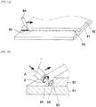
- Fig. 1A shows work of applying the viscous material 95.
- a discharge head 80 that discharges the viscous material 95 is used in the work of applying the viscous material 95.
- the discharge head 80 can be moved close to or away from the joining part 93, and can be moved in an extending direction of the joining part 93.
- the head moving mechanism is operated to move the discharge head 80 in the extending direction of the joining part 93 while appropriately maintaining a clearance between the discharge head 80 and the joining part 93.
- an amount (a volume or weight) of the viscous material 95 applied to the joining part 93 while the discharge head 80 moves by the unit distance is adjusted to fall within a range required for a product.
- the amount is referred to as "coating amount”.
- the viscous material 95 is applied along the extending direction of the joining part 93.
- the viscous material 95 is provided so as to straddle the surface of the first workpiece 91 and the side end surface of the second workpiece 92, and is provided in a bead shape along the extending direction of the joining part 93.
- the viscous material 95 fills a gap between the workpieces 91 and 92.
- the extending direction of the viscous material applied in the bead shape is also referred to as "coating direction”.
- a cross section of the viscous material 95 in Fig. 1B when viewed from outside, even if the viscous material 95 is provided so as to straddle the two workpieces 91 and 92 as described above, air 96 may enter an inside thereof In that case, a contact area of the viscous material 95 with the workpieces 91 and 92 becomes smaller than expected. Then, the viscous material 95 is easily peeled off from the workpieces 91 and 92, and a period in which required performance (for example, sealing performance or joining performance) can be obtained satisfactorily may be shorter than expected. Note that, as an example of a situation in which the air 96 enters, a case where a coating amount required for a product is large can be cited.
- the stirring apparatus 1 includes a stirring member 2.
- the stirring member 2 rotates around a rotation axis A, and its tip is radially separated from the rotation axis A
- the stirring apparatus 1 causes the tip of the stirring member 2 to be immersed in the viscous material 95 applied to the joining part 93 in the coating work, and in this state, causes the stirring member 2 to turn around the rotation axis A and move the stirring member 2 along the coating direction.
- the "turn” includes not only rotation about the rotation axis Abut also revolution about the rotation axis A or eccentric rotation about the rotation axis A
- the air 96 that has entered the inside of the viscous material 95 can be removed, whereby the viscous material 95 properly contacts the workpieces 91 and 92, and a service life of the viscous material 95 is extended (a repair frequency is reduced).
- a configuration and operation of the stirring apparatus 1 will be described in more detail.
- Fig. 2 is a conceptual view showing the stirring apparatus 1
- Fig. 3 is a block diagram showing the stirring apparatus 1.
- the stirring apparatus 1 includes a rotary actuator 3, a moving mechanism 4, and a control device 8, in addition to the stirring member 2 described above.
- the rotary actuator 3 rotates the stirring member 2 around the rotation axis A
- the rotary actuator 3 is configured by, for example, an electric motor.
- the moving mechanism 4 moves the stirring member 2.
- the moving mechanism 4 is, for example, a vertical articulated robot, and includes a robot arm 5 having a plurality of (e.g., six) joints and a plurality (the same number of joints) of moving actuators 6 (see Fig. 3 ) each driving each of the plurality of joints.
- the stirring member 2 and the rotary actuator 3 are unitized by being held by a holding member 7, and the stirring member 2, the rotary actuator 3, and the holding member 7 constitute a stirring head 10.
- the holding member 7 is detachably attached to a tip of the robot arm 5.
- a base of the robot arm 5 is installed on a floor of a work site.
- the workpieces 91 and 92 are held by a jig 90 installed on the floor of the manufacturing site, and positioned within a movable range of the robot arm 5.
- the base of the robot arm 5 may be slidably supported by a traveling rail installed on the floor of the manufacturing site, in which case the moving mechanism 4 includes the traveling rail and a traveling actuator that causes the robot arm 5 to travel along the traveling rail.
- the base of the robot arm 5 may be supported by a pedestal installed on the floor of the manufacturing site.
- control device 8 is, for example, a computer having a memory such as a ROM or a RAM and a CPU, and a program stored in the ROM is executed by the CPU.
- the control device 8 may be a single device or may be divided into a plurality of devices.
- the program stored in the ROM includes a program that teaches a movement locus and moving speed of the tip of the robot arm 5, and execution of the program (i.e., playback) can cause the holding member 7 and the stirring member 2 held by this to move as taught in advance.
- the program stored in the ROM includes a program for deriving a command value of rotation speed of the rotary actuator 3, and the rotation speed of the rotary actuator 3 and thus the stirring member 2 is controlled by executing the program.
- the control device 8 is connected to an operation panel 9.
- the operation panel 9 is operated by an operator at the manufacturing site.
- the CPU of the control device 8 executes the above-described program, and the stirring member 2 is turned and moved.
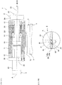
- Fig. 4A is a cross-sectional view of the holding member 7 according to Embodiment 1.
- the holding member 7 has a holding unit 11 for holding the stirring member 2 and the rotary actuator 3 and a mounting unit 12 integrated with the holding unit 11.
- the mounting unit 12 is formed in a disk shape and is detachably attached to the tip of the robot arm 5.
- the holding unit 11 is formed in a tubular shape with both ends opened.
- the holding unit 11 may be a cylinder other than the illustrated rectangular tube.
- the rotary actuator 3 When the rotary actuator 3 is configured by the electric motor as described above, the rotary actuator 3 includes a housing 31 containing a rotor and a stator, a flange 32 provided at one end of the housing 31, and an output shaft 33 protruding from the flange 32 to a side opposite to the housing 31.
- the rotary actuator 3 is held by the holding member 7 by fastening the flange 32 to one end of the holding unit 11 in a state in which the output shaft 33 is inserted into the holding unit 11 through one end opening of the holding unit 11.
- a spacer 13 may be interposed between the holding unit 11 and the flange 32.
- the stirring member 2 includes a driven body 21 and a stirring body 22.
- the driven body 21 has a driven shaft 23 and a disk body 24.
- the driven shaft 23 is partially accommodated in the holding unit 11 through another end opening of the holding unit 11, and one end of the driven shaft 23 is connected to the output shaft 33 of the rotary actuator 3 via a shaft coupling 14 in the holding unit 11. Another end of the driven shaft 23 is located outside the holding unit 11.
- the driven shaft 23 is rotatably supported by bearings 15 and 16 provided in the holding unit 11.
- the disk body 24 is fixed to the other end of the driven shaft 23, and is positioned outside the holding unit 11.
- the stirring body 22 is attached to the disk body 24 of the driven body 21 and protrudes from the disk body 24 to a side opposite to the driven shaft 23 and the rotary actuator 3.
- the stirring body 22 forms a tip of the stirring member 2.
- the output shaft 33, the driven shaft 23, and the disk body 24 are coaxially arranged, and a central axis thereof forms the rotation axis A of the stirring member 2.
- the output shaft 33 does not have to be arranged coaxially with the driven shaft 23.
- the two shafts 33 and 23 may be connected via an orthogonal shaft gear or a staggered shaft gear.
- the gear can be provided with a speed reducing function.
- the speed reducing function may be provided by interposing a strain wave gearing.
- a tip of the stirring body 22 (that is, the tip of the stirring member 2) is radially away from the rotation axis A
- eccentric amount e a radial distance of the tip of the stirring member 2 from the rotation axis A
- the eccentric amount adjusting mechanism 25 can adjust a mounting position of the stirring body 22 to the driven body 21 (disk body 24), which thereby can adjust the eccentric amount e [mm].
- the eccentric amount e can be adjusted within a range of 0 to 10 mm.
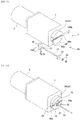
- Fig. 5A is an exploded perspective view of the eccentric amount adjusting mechanism 25, and Fig. 5B is a perspective view showing the eccentric amount adjusting mechanism 25 in an assembled state.
- the eccentric amount adjusting mechanism 25 includes a slider 26 and a male screw 27 provided on the stirring body 22, and a groove 28 provided on the disk body 24.
- the eccentric amount adjusting mechanism 25 further includes a washer 29 and nuts 30.
- the stirring body 22 is formed in a rod shape and extends linearly, for example.
- the tip of the stirring body 22 is tapered. In the illustrated example, it is formed in a hemispherical shape and rounded, but may be formed in a conical shape and sharpened.
- the slider 26 is fixed to a base end of the stirring body 22.
- the stirring body 22 is provided so as to protrude from a center of the slider 26.
- the slider 26 is formed in a square block shape when viewed in a direction of the rotation axis A
- the male screw 27 is located at the base end of the stirring body 22 and slightly closer to the tip side thereof than the slider 26, and is provided on an outer peripheral surface of the stirring body 22.
- the groove 28 is formed linearly along a diameter direction of the disk body 24 (one direction orthogonal to the rotation axis A).
- the groove 28 includes a penetrating part 28a that extends linearly inside the disk body 24 and opens through a peripheral surface of the disk body 24 and an opening part 28b formed on an end surface of the disk body 24 to open the penetrating part 28a outside the disk body 24.
- the penetrating part 28a and the opening part 28b are parallel.
- the slider 26 is received inside the penetrating part 28a through an opening formed on the peripheral surface of the disk body 24, and is slidable in an extending direction of the groove 28 in the penetrating part 28a.
- a height h28b of the opening part 28b is smaller than a height h26 of the slider 26 and larger than an outer diameter ⁇ 22 of the stirring body 22. Therefore, when the slider 26 is received by the penetrating part 28a, the stirring body 22 can protrude out of the disk body 24 through the opening part 28b, whereas the slider 26 is prevented from falling off
- the male screw 27 is positioned outside the disk body 24 and near the end surface of the disk body 24.
- the washer 29 is inserted through the stirring body 22 from the tip side of the stirring body 22, and then the nuts 30 are fastened to the male screw 27.
- the disk body 24 is sandwiched between the slider 26 and the washer 29, and the stirring body 22 is fixed to the driven body 21.
- a through bolt type fastening structure is employed, and the slider 26 has the same function as a bolt head in the fastening structure. Before the fastening, a position of the slider 26 in the penetrating part 28a is adjusted while sliding the slider 26, thereby adjusting the eccentric amount e (see Fig. 4B ).
- the eccentric amount e can be changed in accordance with a coating amount of the viscous material 95 to be subjected to air bleeding work, and air can be removed regardless of the coating amount of the viscous material 95. Since a double nut type fastening structure is employed, the screw is not easily loosened, and the eccentric amount e after the fastening can be prevented from undesirably changing.
- Air bleeding work using the stirring apparatus 1 having the above configuration starts when a command is input by an operator on the operation panel 9.
- operation of the actuator described below is based on the control of the control device 8.
- the moving actuator 6 operates, a posture of the robot arm 5 and a position and a posture of the stirring member 2 change, and the tip of the stirring member 2 faces a stirring start position of the viscous material 95 applied to the joining part 93 as a result of the coating work (see Fig. 1B or 2 ).
- the stirring start position is any end of the viscous material 95.
- the viscous material 95 may be applied in a closed loop shape.
- the stirring start position is an arbitrary position of the viscous material 95 or a starting point/end point position of the coating work.
- the moving actuator 6 continues to operate, and the tip of the stirring member 2 is immersed at the above-described stirring start position of the applied viscous material 95 (see Fig. 1B or Fig. 6 ).
- the tip of the stirring member 2 (stirring body 22) forms an immersion part 2a immersed inside the viscous material 95 (see Fig. 6 ).
- the rotary actuator 3 operates, and the stirring member 2 turns around the rotation axis A
- the moving actuator 6 operates, and the stirring member 2 moves along the coating direction of the viscous material 95 while the tip of the stirring member 2 is immersed in the viscous material 95.
- the immersion part 2a moves in the coating direction from the stirring start position while rotating eccentrically with respect to the rotation axis A
- a movement locus T of the immersion part 2a is a series of a plurality of ellipses arranged in the coating direction.
- the turning and moving steps of the stirring member 2 are performed until the immersion part 2a reaches a stirring end position of the viscous material 95.
- the stirring end position is an end of the viscous material 95 opposite to the stirring start position.
- the stirring end position is the same as the stirring start position.
- the stirring member 2 When the stirring member 2 is turned and moved while the tip of the stirring member 2 is immersed in the viscous material 95, the immersion part 2a moves along the movement locus T while pushing away the viscous material 95. Accordingly, the viscous material 95 is stirred by the immersion part 2a In the viscous material 95, a passage mark 95a of the immersion part 2a is formed on a downstream side of the movement locus T with respect to the immersion part 2a. The air that has entered the inside of the viscous material 95 flows out of the viscous material 95 around the immersion part 2a, particularly through the passage mark 95a.
- the rotary actuator 3 rotates the stirring member 2 at a constant rotation speed n [rpm] (an angular velocity ⁇ [rad/s] of the stirring member 2 is 2 ⁇ n/60).
- the moving actuator 6 moves the stirring member 2 at a constant moving speed v[mm/s].
- x ecos ⁇ t + vt
- y esin ⁇ t
- t is elapsed time [s] from the start of rotation and movement of the immersion part 2a
- x is an x coordinate
- y is a y coordinate after t seconds from the start of rotation and movement of the immersion part 2a
- e, ⁇ , and v are the above-described eccentric amount [mm], angular velocity [rad/s], and moving speed [mm/s].
- the rotation speed n is set within a range of 50 to 100 rpm.
- the speed relatively low By setting the speed relatively low in this way, the applied viscous material 95 is not disturbed, and the viscous material 95 can be stirred while maintaining a state in which the viscous material 95 is applied to the joining part 93.
- the moving speed v is too low, the movement locus T will be like a plurality of ellipses overlapping one another, and the viscous material 95 will be disturbed.
- the moving speed v is set so that a plurality of ellipses constituting the movement locus T circumscribes each other, overlaps with a small amount of overlap, or is arranged with a small clearance.
- the moving speed v is set in a range of 0.1 to 15 m/min (1.7 to 250 mm/s). Thereby, the air 96 can be uniformly discharged without disturbing the viscous material 95 regardless of the position in the coating direction.
- the air bleeding work that has been performed manually until now can be automated. For this reason, it contributes to labor saving of work accompanying the viscous material coating work.
- Fig. 7 is a perspective view showing a holding member 107 of a stirring apparatus 101 according to Embodiment 2.
- the stirring head 10 (unit including the stirring member 2, the rotary actuator 3, and the holding unit 11 of the holding member 7) according to Embodiment 1 is mounted on a base 113 of the holding member 107.
- a discharge head 180 is mounted on the base 113 adjacent to the stirring head 10.
- the discharge head 180 has a housing 181, a discharge actuator 182, and a nozzle 183.
- the housing 181 has a storage unit that stores a viscous material, a plunger that pushes the viscous material stored in the storage unit to the nozzle 183, and the like.
- the nozzle 183 discharges the viscous material supplied from the storage unit.
- the discharge actuator 182 is a power source of the plunger. When the discharge actuator 182 operates, the viscous material is discharged from the nozzle 183.
- the discharge actuator 182 is configured by, for example, an electric motor.
- a mounting unit 112 of the holding member 107 is integrated with the base 113, and is detachably attached to a moving mechanism (for example, a tip of a robot arm of a vertical articulated robot) in the same manner as in Embodiment 1.
- a moving mechanism for example, a tip of a robot arm of a vertical articulated robot
- the stirring head 10 for performing air bleeding work and the discharge head 180 for discharging the viscous material are unitized. Therefore, coating work and the air bleeding work can be performed in parallel.
- the stirring apparatus 101 according to Embodiment 2 also includes a control device 8 and an operation panel 9 (see Fig. 3 ) in the same manner as in Embodiment 1.
- the control device 8 performs the viscous material coating work and the air bleeding work.
- the control device 8 drives the moving mechanism to move the holding member 107 so that the discharge head 180 is on a front side in a moving direction of the holding member 107 and the stirring member 2 is on a rear side in the moving direction of the holding member 107.
- the control device 8 drives the discharge head 180 (discharge actuator 182) to apply the viscous material to workpieces, and drives the rotary actuator 3 to rotate the stirring member 2 around a rotation axis A
- the stirring member 2 only needs to have its tip radially away from the rotation axis A, and a shape of the stirring body 22 is not limited to a rod shape.
- the stirring body 22 may have a crank shape. In the steps of turning and moving the stirring member 2, the rotation speed n and the moving speed v may be changed.
- the holding member 7 can be omitted.
- the stirring member 2 may be detachably attached to the tip of the robot arm 5.
- the actuator corresponding to the joint closest to the tip side functions as the rotary actuator 3 that drives the stirring member 2 to rotate, and the remaining actuators function as the moving actuators 6 that move the stirring member 2.
- the moving mechanism 4 is not limited to the vertical articulated robot.
Landscapes
- Chemical & Material Sciences (AREA)
- Chemical Kinetics & Catalysis (AREA)
- Mixers Of The Rotary Stirring Type (AREA)
- Coating Apparatus (AREA)
- Application Of Or Painting With Fluid Materials (AREA)
Abstract
Description
- The present invention relates to an apparatus and a method for stirring a viscous material such as a sealant or an adhesive.
- At a manufacturing site of vehicles or industrial machinery, automation of work of applying a viscous material to a joining part of two components is underway. For example, PTL1 discloses a viscous material coating apparatus that can be applied to an automobile manufacturing site. This apparatus includes a mixing head attached to a robot hand and discharging a sealant while moving along a predetermined locus.
- PTL 1:
JP 6-269720 A - In some situations, air may get inside the applied viscous material. In order to improve or stabilize construction quality, in viscous material coating work, work of bleeding air that has entered inside the viscous material may be performed incidentally.
- This incidental work is performed manually by a worker at the manufacturing site, which places a heavy burden on the worker. In order to stably maintain the construction quality under such circumstances, it is essential to train workers skilled in the incidental work, but this requires a great deal of time and money.
- Therefore, an object of the present invention is to provide an apparatus and a method that contribute to labor saving of work accompanying viscous material coating work.
- A viscous material stirring apparatus according to one aspect of the present invention that is an apparatus for stirring a viscous material applied to workpieces, the viscous material stirring apparatus including: a stirring member that rotates around a rotation axis and has a tip radially separated from the rotation axis; a rotary actuator that rotates the stirring member about the rotation axis; a moving mechanism that moves the stirring member, and a control device, in which the control device is configured so that the moving mechanism is driven to immerse the tip of the stirring member in the applied viscous material, that the rotary actuator is driven to rotate the stirring member about the rotation axis, and that the moving mechanism is driven to move the stirring member along a coating direction of the viscous material with the tip of the stirring member immersed in the viscous material.
- A viscous material stirring method according to one aspect of the present invention that is a method for stirring a viscous material applied to workpieces, the viscous material stirring method including: moving a stirring member by a moving mechanism to immerse a tip of the stirring member in the applied viscous material, and with the tip of the stirring member immersed in the viscous material, turning the stirring member around a predetermined rotation axis by a rotary actuator, and moving the stirring member along a coating direction of the viscous material by the moving mechanism.
- According to the above-described apparatus and method, the stirring member moves in the coating direction of the viscous material while eccentrically rotating with the tip of the stirring member immersed in the viscous material. The applied viscous material is stirred by the tip of the stirring member. Thus, even if air enters inside the viscous material, the air can be extracted from a periphery of the eccentrically rotating stirring member to the outside of the viscous material. In this way, air bleeding work can be automated by operating the rotary actuator and the moving mechanism.
- According to the present invention, an apparatus and a method which contribute to labor saving of work accompanying viscous material coating work can be provided.
-
-
Fig. 1A is an explanatory view of viscous material coating work performed at a manufacturing site to which an apparatus and a method for stirring a viscous material according toEmbodiment 1 are applied. -
Fig. 1B is an explanatory view of an air bleeding work performed at the manufacturing site, and is a view illustrating a step of immersing a tip of a stirring member in the viscous material. -
Fig. 2 is a conceptual view showing the viscous material stirring apparatus according toEmbodiment 1. -
Fig. 3 is a block diagram showing the viscous material stirring apparatus according toEmbodiment 1. -
Fig. 4A is a cross-sectional view of a holding member according to Embodiment 1. -
Fig. 4B is a view taken in a direction of arrow B inFig. 4A , that is, a view showing the stirring member viewed in a direction of its rotation axis. -
Fig. 5A is an exploded perspective view of an eccentric amount adjusting mechanism, andFig. 5B is a perspective view showing the eccentric amount adjusting mechanism in an assembled state. -
Fig. 6 is an explanatory view of viscous material stirring work, and is a view showing steps of turning the tip of the stirring member and moving the stirring member. -
Fig. 7 is a perspective view showing a holding member of a viscous material stirring apparatus according to Embodiment 2. - Hereinafter, embodiments will be described with reference to the drawings. The same or corresponding elements are denoted by the same reference signs throughout the drawings, and redundant detailed description will be omitted.
-
Figs. 1A and 1B show a manufacturing site to which a viscous material stirring apparatus 1 (hereinafter, simply referred to as "stirringapparatus 1") according toEmbodiment 1 is applied. In this manufacturing site, aviscous material 95 is applied to a joiningpart 93 ofworkpieces workpieces - As an example of a manufacturing site, a manufacturing site of a vehicle (for example, an aircraft or an automobile) or industrial machinery (for example, a construction machine, an agricultural machine, or a machine tool) can be cited.
- In the present embodiment, as an example, the
workpieces part 93 is formed by overlapping theworkpieces part 93 is formed by a surface of thefirst workpiece 91 and a side end surface of thesecond workpiece 92, forms a right angle, and extends along the side end surface of thesecond workpiece 92. At an aircraft manufacturing site, theworkpieces - The
viscous material 95 is a material having viscosity such as a sealant or an adhesive. As an example, theviscous material 95 has a viscosity of 1500 to 2000 Pa · s when applied under a normal temperature environment (for example, 20 to 25°C). However, both the sealant and the adhesive harden (the viscosity increases) with the lapse of time after being applied to the joiningpart 93 due to influence of moisture or heating at the manufacturing site. -
Fig. 1A shows work of applying theviscous material 95. As shown inFig. 1A , adischarge head 80 that discharges theviscous material 95 is used in the work of applying theviscous material 95. By a head moving mechanism (not shown), thedischarge head 80 can be moved close to or away from the joiningpart 93, and can be moved in an extending direction of the joiningpart 93. In the coating work, while thedischarge head 80 is operated to discharge theviscous material 95 to the joiningpart 93, the head moving mechanism is operated to move thedischarge head 80 in the extending direction of the joiningpart 93 while appropriately maintaining a clearance between thedischarge head 80 and the joiningpart 93. By adjusting discharge speed and moving speed, an amount (a volume or weight) of theviscous material 95 applied to the joiningpart 93 while thedischarge head 80 moves by the unit distance is adjusted to fall within a range required for a product. Hereinafter, the amount is referred to as "coating amount". - By this coating work, the
viscous material 95 is applied along the extending direction of the joiningpart 93. In the present embodiment, theviscous material 95 is provided so as to straddle the surface of thefirst workpiece 91 and the side end surface of thesecond workpiece 92, and is provided in a bead shape along the extending direction of the joiningpart 93. Thus, theviscous material 95 fills a gap between theworkpieces - As shown in a cross section of the
viscous material 95 inFig. 1B , when viewed from outside, even if theviscous material 95 is provided so as to straddle the twoworkpieces air 96 may enter an inside thereof In that case, a contact area of theviscous material 95 with theworkpieces viscous material 95 is easily peeled off from theworkpieces air 96 enters, a case where a coating amount required for a product is large can be cited. - At this manufacturing site, after the work of applying the
viscous material 95, work of bleeding theair 96 that has entered the inside of theviscous material 95 is performed incidentally. Previously, the air bleeding work has been manually performed by an operator using a comb tool made of wood or synthetic resin, but thestirring apparatus 1 is applied to the manufacturing site for automation of the air bleeding work - The stirring
apparatus 1 includes a stirringmember 2. The stirringmember 2 rotates around a rotation axis A, and its tip is radially separated from the rotation axis A The stirringapparatus 1 causes the tip of the stirringmember 2 to be immersed in theviscous material 95 applied to the joiningpart 93 in the coating work, and in this state, causes the stirringmember 2 to turn around the rotation axis A and move the stirringmember 2 along the coating direction. Here, the "turn" includes not only rotation about the rotation axis Abut also revolution about the rotation axis A or eccentric rotation about the rotation axis A Thereby, theair 96 that has entered the inside of theviscous material 95 can be removed, whereby theviscous material 95 properly contacts theworkpieces viscous material 95 is extended (a repair frequency is reduced). Hereinafter, a configuration and operation of thestirring apparatus 1 will be described in more detail. -
Fig. 2 is a conceptual view showing thestirring apparatus 1, andFig. 3 is a block diagram showing thestirring apparatus 1. As shown inFigs. 2 and 3 , the stirringapparatus 1 includes arotary actuator 3, a movingmechanism 4, and acontrol device 8, in addition to the stirringmember 2 described above. Therotary actuator 3 rotates the stirringmember 2 around the rotation axis A Therotary actuator 3 is configured by, for example, an electric motor. The movingmechanism 4 moves the stirringmember 2. The movingmechanism 4 is, for example, a vertical articulated robot, and includes arobot arm 5 having a plurality of (e.g., six) joints and a plurality (the same number of joints) of moving actuators 6 (seeFig. 3 ) each driving each of the plurality of joints. - In the present embodiment, the stirring
member 2 and therotary actuator 3 are unitized by being held by a holdingmember 7, and the stirringmember 2, therotary actuator 3, and the holdingmember 7 constitute a stirringhead 10. The holdingmember 7 is detachably attached to a tip of therobot arm 5. When therobot arm 5 of the movingmechanism 4 operates, the holdingmember 7 and the stirringmember 2 held by the holdingmember 7 move together with therotary actuator 3. - As an example, a base of the
robot arm 5 is installed on a floor of a work site. Theworkpieces jig 90 installed on the floor of the manufacturing site, and positioned within a movable range of therobot arm 5. However, the base of therobot arm 5 may be slidably supported by a traveling rail installed on the floor of the manufacturing site, in which case the movingmechanism 4 includes the traveling rail and a traveling actuator that causes therobot arm 5 to travel along the traveling rail. The base of therobot arm 5 may be supported by a pedestal installed on the floor of the manufacturing site. - As shown in
Fig. 3 , therotary actuator 3 and the movingactuator 6 of the movingmechanism 4 are controlled by thecontrol device 8. Thecontrol device 8 is, for example, a computer having a memory such as a ROM or a RAM and a CPU, and a program stored in the ROM is executed by the CPU. Thecontrol device 8 may be a single device or may be divided into a plurality of devices. - In the present embodiment, the program stored in the ROM includes a program that teaches a movement locus and moving speed of the tip of the
robot arm 5, and execution of the program (i.e., playback) can cause the holdingmember 7 and the stirringmember 2 held by this to move as taught in advance. The program stored in the ROM includes a program for deriving a command value of rotation speed of therotary actuator 3, and the rotation speed of therotary actuator 3 and thus the stirringmember 2 is controlled by executing the program. - The
control device 8 is connected to anoperation panel 9. Theoperation panel 9 is operated by an operator at the manufacturing site. When a command to start the air bleeding work is input by the operator at theoperation panel 9, the CPU of thecontrol device 8 executes the above-described program, and the stirringmember 2 is turned and moved. -
Fig. 4A is a cross-sectional view of the holdingmember 7 according toEmbodiment 1. As shown inFig. 4A , the holdingmember 7 has a holdingunit 11 for holding the stirringmember 2 and therotary actuator 3 and a mountingunit 12 integrated with the holdingunit 11. Although not shown in detail, the mountingunit 12 is formed in a disk shape and is detachably attached to the tip of therobot arm 5. The holdingunit 11 is formed in a tubular shape with both ends opened. The holdingunit 11 may be a cylinder other than the illustrated rectangular tube. - When the
rotary actuator 3 is configured by the electric motor as described above, therotary actuator 3 includes ahousing 31 containing a rotor and a stator, aflange 32 provided at one end of thehousing 31, and anoutput shaft 33 protruding from theflange 32 to a side opposite to thehousing 31. Therotary actuator 3 is held by the holdingmember 7 by fastening theflange 32 to one end of the holdingunit 11 in a state in which theoutput shaft 33 is inserted into the holdingunit 11 through one end opening of the holdingunit 11. Aspacer 13 may be interposed between the holdingunit 11 and theflange 32. - The stirring
member 2 includes a drivenbody 21 and a stirringbody 22. In the present embodiment, the drivenbody 21 has a drivenshaft 23 and adisk body 24. The drivenshaft 23 is partially accommodated in the holdingunit 11 through another end opening of the holdingunit 11, and one end of the drivenshaft 23 is connected to theoutput shaft 33 of therotary actuator 3 via ashaft coupling 14 in the holdingunit 11. Another end of the drivenshaft 23 is located outside the holdingunit 11. The drivenshaft 23 is rotatably supported bybearings unit 11. Thedisk body 24 is fixed to the other end of the drivenshaft 23, and is positioned outside the holdingunit 11. The stirringbody 22 is attached to thedisk body 24 of the drivenbody 21 and protrudes from thedisk body 24 to a side opposite to the drivenshaft 23 and therotary actuator 3. The stirringbody 22 forms a tip of the stirringmember 2. - In the present embodiment, the
output shaft 33, the drivenshaft 23, and thedisk body 24 are coaxially arranged, and a central axis thereof forms the rotation axis A of the stirringmember 2. However, theoutput shaft 33 does not have to be arranged coaxially with the drivenshaft 23. For example, the twoshafts - When the
rotary actuator 3 operates and theoutput shaft 33 rotates, the stirring member 2 (the drivenbody 21 and the stirring body 22) is driven to rotate around the rotation axis A The stirringbody 22 is attached to thedisk body 24 via an eccentricamount adjusting mechanism 25, and as shown inFig.4B , a tip of the stirring body 22 (that is, the tip of the stirring member 2) is radially away from the rotation axis A When the stirringmember 2 rotates around the rotation axis A, if the tip of the stirringbody 22 is focused, this tip revolves or rotates eccentrically around the rotation axis A Hereinafter, a radial distance of the tip of the stirringmember 2 from the rotation axis A is referred to as "eccentric amount e". The eccentricamount adjusting mechanism 25 can adjust a mounting position of the stirringbody 22 to the driven body 21 (disk body 24), which thereby can adjust the eccentric amount e [mm]. As an example, the eccentric amount e can be adjusted within a range of 0 to 10 mm. -
Fig. 5A is an exploded perspective view of the eccentricamount adjusting mechanism 25, andFig. 5B is a perspective view showing the eccentricamount adjusting mechanism 25 in an assembled state. As an example, the eccentricamount adjusting mechanism 25 includes aslider 26 and amale screw 27 provided on the stirringbody 22, and agroove 28 provided on thedisk body 24. The eccentricamount adjusting mechanism 25 further includes awasher 29 and nuts 30. - The stirring
body 22 is formed in a rod shape and extends linearly, for example. The tip of the stirringbody 22 is tapered. In the illustrated example, it is formed in a hemispherical shape and rounded, but may be formed in a conical shape and sharpened. - The
slider 26 is fixed to a base end of the stirringbody 22. In other words, the stirringbody 22 is provided so as to protrude from a center of theslider 26. As an example, theslider 26 is formed in a square block shape when viewed in a direction of the rotation axis A Themale screw 27 is located at the base end of the stirringbody 22 and slightly closer to the tip side thereof than theslider 26, and is provided on an outer peripheral surface of the stirringbody 22. - The
groove 28 is formed linearly along a diameter direction of the disk body 24 (one direction orthogonal to the rotation axis A). Thegroove 28 includes apenetrating part 28a that extends linearly inside thedisk body 24 and opens through a peripheral surface of thedisk body 24 and anopening part 28b formed on an end surface of thedisk body 24 to open thepenetrating part 28a outside thedisk body 24. The penetratingpart 28a and theopening part 28b are parallel. Theslider 26 is received inside the penetratingpart 28a through an opening formed on the peripheral surface of thedisk body 24, and is slidable in an extending direction of thegroove 28 in thepenetrating part 28a. A height h28b of theopening part 28b is smaller than a height h26 of theslider 26 and larger than an outer diameter ϕ22 of the stirringbody 22. Therefore, when theslider 26 is received by the penetratingpart 28a, the stirringbody 22 can protrude out of thedisk body 24 through theopening part 28b, whereas theslider 26 is prevented from falling off - When the
slider 26 is received inside the penetratingpart 28a, themale screw 27 is positioned outside thedisk body 24 and near the end surface of thedisk body 24. Thewasher 29 is inserted through the stirringbody 22 from the tip side of the stirringbody 22, and then the nuts 30 are fastened to themale screw 27. By this fastening, thedisk body 24 is sandwiched between theslider 26 and thewasher 29, and the stirringbody 22 is fixed to the drivenbody 21. A through bolt type fastening structure is employed, and theslider 26 has the same function as a bolt head in the fastening structure. Before the fastening, a position of theslider 26 in thepenetrating part 28a is adjusted while sliding theslider 26, thereby adjusting the eccentric amount e (seeFig. 4B ). The eccentric amount e can be changed in accordance with a coating amount of theviscous material 95 to be subjected to air bleeding work, and air can be removed regardless of the coating amount of theviscous material 95. Since a double nut type fastening structure is employed, the screw is not easily loosened, and the eccentric amount e after the fastening can be prevented from undesirably changing. - Air bleeding work using the
stirring apparatus 1 having the above configuration starts when a command is input by an operator on theoperation panel 9. Note that operation of the actuator described below is based on the control of thecontrol device 8. When the command is input, the movingactuator 6 operates, a posture of therobot arm 5 and a position and a posture of the stirringmember 2 change, and the tip of the stirringmember 2 faces a stirring start position of theviscous material 95 applied to the joiningpart 93 as a result of the coating work (seeFig. 1B or2 ). When theviscous material 95 is applied in a line segment shape having both ends, the stirring start position is any end of theviscous material 95. Theviscous material 95 may be applied in a closed loop shape. In this case, the stirring start position is an arbitrary position of theviscous material 95 or a starting point/end point position of the coating work. - The moving
actuator 6 continues to operate, and the tip of the stirringmember 2 is immersed at the above-described stirring start position of the applied viscous material 95 (seeFig. 1B orFig. 6 ). The tip of the stirring member 2 (stirring body 22) forms animmersion part 2a immersed inside the viscous material 95 (seeFig. 6 ). - Referring to
Fig. 6 , after this immersion step, therotary actuator 3 operates, and the stirringmember 2 turns around the rotation axis A At the same time, the movingactuator 6 operates, and the stirringmember 2 moves along the coating direction of theviscous material 95 while the tip of the stirringmember 2 is immersed in theviscous material 95. Theimmersion part 2a moves in the coating direction from the stirring start position while rotating eccentrically with respect to the rotation axis A A movement locus T of theimmersion part 2a is a series of a plurality of ellipses arranged in the coating direction. - The turning and moving steps of the stirring
member 2 are performed until theimmersion part 2a reaches a stirring end position of theviscous material 95. When theviscous material 95 is applied in a line segment shape, the stirring end position is an end of theviscous material 95 opposite to the stirring start position. When theviscous material 95 is applied in a closed loop shape, the stirring end position is the same as the stirring start position. When theimmersion part 2a moves to the stirring end position, the movingactuator 6 operates to retreat the stirringmember 2 from theviscous material 95. In this retreat step, before or during the retreat movement by the movingactuator 6, therotary actuator 3 stops and the turn of the stirringmember 2 stops. - When the stirring
member 2 is turned and moved while the tip of the stirringmember 2 is immersed in theviscous material 95, theimmersion part 2a moves along the movement locus T while pushing away theviscous material 95. Accordingly, theviscous material 95 is stirred by theimmersion part 2a In theviscous material 95, apassage mark 95a of theimmersion part 2a is formed on a downstream side of the movement locus T with respect to theimmersion part 2a. The air that has entered the inside of theviscous material 95 flows out of theviscous material 95 around theimmersion part 2a, particularly through thepassage mark 95a. - The
rotary actuator 3 rotates the stirringmember 2 at a constant rotation speed n [rpm] (an angular velocity ω [rad/s] of the stirringmember 2 is 2πn/60). The movingactuator 6 moves the stirringmember 2 at a constant moving speed v[mm/s]. In this case, when a two-dimensional orthogonal coordinate system in which the coating direction is an x direction and a direction orthogonal to the coating direction and the direction of the rotation axis A is a y direction is assumed, the movement locus T of theimmersion part 2a is represented in the following equation (1).
- Here, t is elapsed time [s] from the start of rotation and movement of the
immersion part 2a, and x is an x coordinate and y is a y coordinate after t seconds from the start of rotation and movement of theimmersion part 2a Note that e, ω, and v are the above-described eccentric amount [mm], angular velocity [rad/s], and moving speed [mm/s]. - As an example, the rotation speed n is set within a range of 50 to 100 rpm. By setting the speed relatively low in this way, the applied
viscous material 95 is not disturbed, and theviscous material 95 can be stirred while maintaining a state in which theviscous material 95 is applied to the joiningpart 93. In this case, if the moving speed v is too low, the movement locus T will be like a plurality of ellipses overlapping one another, and theviscous material 95 will be disturbed. If the moving speed v is too high, a plurality of ellipses will be arranged at a large interval in the coating direction, and an unstirred region will be created Therefore, the moving speed v is set so that a plurality of ellipses constituting the movement locus T circumscribes each other, overlaps with a small amount of overlap, or is arranged with a small clearance. As an example, the moving speed v is set in a range of 0.1 to 15 m/min (1.7 to 250 mm/s). Thereby, theair 96 can be uniformly discharged without disturbing theviscous material 95 regardless of the position in the coating direction. - As described above, in the present embodiment, the air bleeding work that has been performed manually until now can be automated. For this reason, it contributes to labor saving of work accompanying the viscous material coating work.
-
Fig. 7 is a perspective view showing a holdingmember 107 of astirring apparatus 101 according toEmbodiment 2. In the present embodiment, the stirring head 10 (unit including the stirringmember 2, therotary actuator 3, and the holdingunit 11 of the holding member 7) according toEmbodiment 1 is mounted on abase 113 of the holdingmember 107. Adischarge head 180 is mounted on the base 113 adjacent to the stirringhead 10. Thedischarge head 180 has ahousing 181, adischarge actuator 182, and anozzle 183. Although not shown in detail, thehousing 181 has a storage unit that stores a viscous material, a plunger that pushes the viscous material stored in the storage unit to thenozzle 183, and the like. Thenozzle 183 discharges the viscous material supplied from the storage unit. Thedischarge actuator 182 is a power source of the plunger. When thedischarge actuator 182 operates, the viscous material is discharged from thenozzle 183. Thedischarge actuator 182 is configured by, for example, an electric motor. - A mounting
unit 112 of the holdingmember 107 is integrated with thebase 113, and is detachably attached to a moving mechanism (for example, a tip of a robot arm of a vertical articulated robot) in the same manner as inEmbodiment 1. - In the
stirring apparatus 101 according to the present embodiment, the stirringhead 10 for performing air bleeding work and thedischarge head 180 for discharging the viscous material are unitized. Therefore, coating work and the air bleeding work can be performed in parallel. - Although not shown in detail, the stirring
apparatus 101 according toEmbodiment 2 also includes acontrol device 8 and an operation panel 9 (seeFig. 3 ) in the same manner as inEmbodiment 1. When a work start command is input on theoperation panel 9, thecontrol device 8 performs the viscous material coating work and the air bleeding work. - In other words, the
control device 8 drives the moving mechanism to move the holdingmember 107 so that thedischarge head 180 is on a front side in a moving direction of the holdingmember 107 and the stirringmember 2 is on a rear side in the moving direction of the holdingmember 107. In a process of moving the holdingmember 107, thecontrol device 8 drives the discharge head 180 (discharge actuator 182) to apply the viscous material to workpieces, and drives therotary actuator 3 to rotate the stirringmember 2 around a rotation axis A This allows the viscous material to be stirred in the same manner as inEmbodiment 1 by immersing a tip of the stirringmember 2 in the viscous material immediately after being applied while performing the work of applying the viscous material to a joining part of the workpieces. Since the coating work and the air bleeding work can be performed in parallel, production efficiency at a manufacturing site is improved. - The embodiments have been described above, but the above configurations can be appropriately changed, added, and/or deleted within the scope of the present invention.
- The stirring
member 2 only needs to have its tip radially away from the rotation axis A, and a shape of the stirringbody 22 is not limited to a rod shape. As an example, the stirringbody 22 may have a crank shape. In the steps of turning and moving the stirringmember 2, the rotation speed n and the moving speed v may be changed. - The holding
member 7 can be omitted. When the movingmechanism 4 is a vertical articulated robot and a joint closest to the tip side is a torsion shaft (so-called T shaft), the stirringmember 2 may be detachably attached to the tip of therobot arm 5. In this case, of the plurality of actuators that drives the joints of the vertical articulated robot, the actuator corresponding to the joint closest to the tip side functions as therotary actuator 3 that drives the stirringmember 2 to rotate, and the remaining actuators function as the movingactuators 6 that move the stirringmember 2. Note that the movingmechanism 4 is not limited to the vertical articulated robot. -
- 1, 101
- viscous material stirring apparatus
- 2
- stirring member
- 3
- rotary actuator
- 4
- moving mechanism
- 7, 107
- holding member
- 8
- control device
- 25
- eccentric amount adjusting mechanism
- 80,180
- discharge head
- 91,92
- workpiece
- 95
- viscous material
- A
- rotation axis
- e
- eccentric amount
Claims (5)
- A viscous material stirring apparatus that is an apparatus for stirring a viscous material applied to workpieces, the viscous material stirring apparatus comprising:a stirring member that rotates around a rotation axis and has a tip radially separated from the rotation axis;a rotary actuator that rotates the stirring member about the rotation axis;a moving mechanism that moves the stirring member, anda control device,wherein the control device is configured so thatthe moving mechanism is driven to immerse the tip of the stirring member in the applied viscous material, andthe rotary actuator is driven to rotate the stirring member about the rotation axis, and the moving mechanism is driven to move the stirring member along a coating direction of the viscous material with the tip of the stirring member immersed in the viscous material.
- The viscous material stirring apparatus according to claim 1, wherein the stirring member is provided with an eccentric amount adjusting mechanism that adjusts an eccentric amount that is a radial distance of the tip from the rotation axis.
- The viscous material stirring apparatus according to claim 1 or 2, further comprising a holding member that holds the stirring member and the rotary actuator,
wherein the holding member is detachably attached to the moving mechanism. - The viscous material stirring apparatus according to claim 3, further comprising a discharge head that is held by the holding member and discharges the viscous material,
wherein the control device is configured so that
the moving mechanism is driven to move the holding member in a posture in which the discharge head is on a front side in a moving direction of the holding member and the stirring member is on a rear side in the moving direction of the holding member, and
in a process of moving the holding member, the discharge head is driven to apply the viscous material to the workpieces, and the rotary actuator is driven to rotate the stirring member about the rotation axis. - A viscous material stirring method that is a method for stirring a viscous material applied to workpieces, the viscous material stirring method comprising:moving a stirring member by a moving mechanism to immerse a tip of the stirring member in the applied viscous material, andwith the tip of the stirring member immersed in the viscous material, turning the stirring member around a predetermined rotation axis by a rotary actuator, and moving the stirring member along a coating direction of the viscous material by the moving mechanism.
Applications Claiming Priority (2)
| Application Number | Priority Date | Filing Date | Title |
|---|---|---|---|
| JP2017165809A JP6864586B2 (en) | 2017-08-30 | 2017-08-30 | Viscous material agitator and viscous material agitation method |
| PCT/JP2018/029758 WO2019044437A1 (en) | 2017-08-30 | 2018-08-08 | Viscous material stirring device and viscous material stirring method |
Publications (3)
| Publication Number | Publication Date |
|---|---|
| EP3677344A1 true EP3677344A1 (en) | 2020-07-08 |
| EP3677344A4 EP3677344A4 (en) | 2021-07-07 |
| EP3677344B1 EP3677344B1 (en) | 2025-03-19 |
Family
ID=65524947
Family Applications (1)
| Application Number | Title | Priority Date | Filing Date |
|---|---|---|---|
| EP18850158.9A Active EP3677344B1 (en) | 2017-08-30 | 2018-08-08 | Viscous material stirring device and viscous material stirring method |
Country Status (5)
| Country | Link |
|---|---|
| US (1) | US11857934B2 (en) |
| EP (1) | EP3677344B1 (en) |
| JP (1) | JP6864586B2 (en) |
| ES (1) | ES3029755T3 (en) |
| WO (1) | WO2019044437A1 (en) |
Cited By (1)
| Publication number | Priority date | Publication date | Assignee | Title |
|---|---|---|---|---|
| CN116059911A (en) * | 2023-03-13 | 2023-05-05 | 山东省路桥集团有限公司 | A continuous batching system for polymer asphalt production |
Families Citing this family (6)
| Publication number | Priority date | Publication date | Assignee | Title |
|---|---|---|---|---|
| JP6864586B2 (en) * | 2017-08-30 | 2021-04-28 | 川崎重工業株式会社 | Viscous material agitator and viscous material agitation method |
| WO2020184349A1 (en) | 2019-03-08 | 2020-09-17 | 日本製鉄株式会社 | Vehicle body lower structure |
| CN112608697A (en) * | 2020-12-05 | 2021-04-06 | 石月(天津)云科技有限公司 | Formaldehyde-free plate adhesive and preparation process thereof |
| JP7834987B2 (en) | 2021-11-09 | 2026-03-25 | 新東工業株式会社 | Processing method and processing apparatus for a workpiece |
| CN120733621B (en) * | 2025-09-03 | 2025-11-04 | 山西伟创新材料科技有限公司 | A water removal device for sealant processing |
| CN121338589B (en) * | 2025-12-18 | 2026-02-24 | 重庆华孚工业股份有限公司 | Mixing device and method for powder metallurgy |
Family Cites Families (13)
| Publication number | Priority date | Publication date | Assignee | Title |
|---|---|---|---|---|
| US3271492A (en) * | 1965-02-01 | 1966-09-06 | Elmendorf Res Inc | Method of making a non-porous board composed of strands of wood and portland cement |
| DE2335814B2 (en) * | 1973-07-13 | 1976-04-22 | Bison-Werke Bahre und Greten GmbH & Co KG, 3257 Springe | PROCESS FOR MIXING INGREDIENTS FOR THE PRODUCTION OF CHIP FIBER - O.DGL. -PLATES OF MIXED MATERIALS OF DIFFERENT PROPERTIES BEFORE THE DOSED FEED TO A BUMPER DEVICE |
| JPH06269720A (en) | 1993-03-19 | 1994-09-27 | Toyota Motor Corp | Viscous material coating device |
| FR2712512B1 (en) * | 1993-11-18 | 1996-02-02 | Seva | Device and installation for mixing viscous and / or fluid products and use of such a device. |
| JPH08277381A (en) | 1994-04-08 | 1996-10-22 | Morioka Seiko Kogyo Kk | Bonding device and bonding method |
| JPH10337521A (en) * | 1997-06-03 | 1998-12-22 | Toyo Tire & Rubber Co Ltd | Method and apparatus for spraying urethane stock solution in urethane continuous foaming process |
| JP3460623B2 (en) * | 1999-05-20 | 2003-10-27 | ソニーケミカル株式会社 | Coating device |
| JP2001070866A (en) * | 1999-09-07 | 2001-03-21 | Konica Corp | Coating method and coating device |
| JP4050931B2 (en) * | 2002-04-22 | 2008-02-20 | 株式会社リコー | Bar coating method |
| JP2005243138A (en) * | 2004-02-26 | 2005-09-08 | Dainippon Ink & Chem Inc | Receiving layer forming method and receiving layer forming apparatus for inkjet recording |
| JP6347640B2 (en) | 2014-03-27 | 2018-06-27 | 新明和工業株式会社 | Coating device |
| JP6432236B2 (en) * | 2014-09-17 | 2018-12-05 | 富士ゼロックス株式会社 | Powder coating apparatus and powder coating method |
| JP6864586B2 (en) * | 2017-08-30 | 2021-04-28 | 川崎重工業株式会社 | Viscous material agitator and viscous material agitation method |
-
2017
- 2017-08-30 JP JP2017165809A patent/JP6864586B2/en active Active
-
2018
- 2018-08-08 EP EP18850158.9A patent/EP3677344B1/en active Active
- 2018-08-08 US US16/643,747 patent/US11857934B2/en active Active
- 2018-08-08 ES ES18850158T patent/ES3029755T3/en active Active
- 2018-08-08 WO PCT/JP2018/029758 patent/WO2019044437A1/en not_active Ceased
Cited By (1)
| Publication number | Priority date | Publication date | Assignee | Title |
|---|---|---|---|---|
| CN116059911A (en) * | 2023-03-13 | 2023-05-05 | 山东省路桥集团有限公司 | A continuous batching system for polymer asphalt production |
Also Published As
| Publication number | Publication date |
|---|---|
| EP3677344A4 (en) | 2021-07-07 |
| EP3677344B1 (en) | 2025-03-19 |
| US11857934B2 (en) | 2024-01-02 |
| JP2019042634A (en) | 2019-03-22 |
| ES3029755T3 (en) | 2025-06-25 |
| JP6864586B2 (en) | 2021-04-28 |
| WO2019044437A1 (en) | 2019-03-07 |
| US20200276548A1 (en) | 2020-09-03 |
Similar Documents
| Publication | Publication Date | Title |
|---|---|---|
| EP3677344B1 (en) | Viscous material stirring device and viscous material stirring method | |
| RU2616477C2 (en) | Device for riveting of aircraft fuselage | |
| JP6458115B2 (en) | Method and apparatus for matching assembly system to curved contour | |
| US8651046B1 (en) | Robotic sealant and end effector | |
| CN101856731B (en) | Automated hole generation | |
| EP2633943B1 (en) | Single-shaft yaw electric bolt-tightening machine | |
| EP3187290B1 (en) | Method for machining a workpiece by a machine tool | |
| JP5383860B2 (en) | Robotic dispensing system | |
| US10596709B2 (en) | Self-contained modular manufacturing tool responsive to locally stored historical data | |
| US20140234011A1 (en) | Fluid Application Device | |
| JP6353252B2 (en) | Coating device | |
| CN106003147A (en) | Robot system and abnormality judgment method | |
| EP3267090A1 (en) | Grease application method and application device | |
| JP6841899B2 (en) | Electronic cam type can lid tightening device | |
| US11642745B2 (en) | Robotic screwdriver and method | |
| JP2018523587A (en) | Robot arm with joints | |
| EP0707919A1 (en) | Method and vibrating welding head for assembling by friction welding or deburring at workpieces | |
| WO2004113002A8 (en) | Orbital machining apparatus with drive element with drive pins | |
| CN110315180B (en) | Spot welding device | |
| CN116997446A (en) | Systems and methods for performing assembly tasks with the aid of robots | |
| JP6441175B2 (en) | Sealant coating apparatus and method for producing sealant coated product | |
| US6125676A (en) | Control system for controlling a rod mill | |
| CN203526454U (en) | Servo pressing-riveting device with automatically gyratory riveting head | |
| KR20260024781A (en) | Apparatus for manufacturing cage windows with position control using a position sensor and ball | |
| CN102009226B (en) | Shearing machine |
Legal Events
| Date | Code | Title | Description |
|---|---|---|---|
| STAA | Information on the status of an ep patent application or granted ep patent |
Free format text: STATUS: THE INTERNATIONAL PUBLICATION HAS BEEN MADE |
|
| PUAI | Public reference made under article 153(3) epc to a published international application that has entered the european phase |
Free format text: ORIGINAL CODE: 0009012 |
|
| STAA | Information on the status of an ep patent application or granted ep patent |
Free format text: STATUS: REQUEST FOR EXAMINATION WAS MADE |
|
| 17P | Request for examination filed |
Effective date: 20200319 |
|
| AK | Designated contracting states |
Kind code of ref document: A1 Designated state(s): AL AT BE BG CH CY CZ DE DK EE ES FI FR GB GR HR HU IE IS IT LI LT LU LV MC MK MT NL NO PL PT RO RS SE SI SK SM TR |
|
| AX | Request for extension of the european patent |
Extension state: BA ME |
|
| DAV | Request for validation of the european patent (deleted) | ||
| DAX | Request for extension of the european patent (deleted) | ||
| A4 | Supplementary search report drawn up and despatched |
Effective date: 20210609 |
|
| RIC1 | Information provided on ipc code assigned before grant |
Ipc: B05C 11/00 20060101AFI20210602BHEP Ipc: B05C 5/00 20060101ALI20210602BHEP Ipc: B05C 9/12 20060101ALI20210602BHEP Ipc: B05D 3/00 20060101ALI20210602BHEP Ipc: B05D 3/12 20060101ALI20210602BHEP Ipc: B05C 5/02 20060101ALI20210602BHEP Ipc: B01F 15/02 20060101ALI20210602BHEP Ipc: B05D 3/02 20060101ALI20210602BHEP |
|
| STAA | Information on the status of an ep patent application or granted ep patent |
Free format text: STATUS: EXAMINATION IS IN PROGRESS |
|
| 17Q | First examination report despatched |
Effective date: 20230602 |
|
| GRAP | Despatch of communication of intention to grant a patent |
Free format text: ORIGINAL CODE: EPIDOSNIGR1 |
|
| STAA | Information on the status of an ep patent application or granted ep patent |
Free format text: STATUS: GRANT OF PATENT IS INTENDED |
|
| RIC1 | Information provided on ipc code assigned before grant |
Ipc: B05D 1/26 20060101ALN20241015BHEP Ipc: B05C 5/00 20060101ALI20241015BHEP Ipc: B05C 9/12 20060101ALI20241015BHEP Ipc: B05D 3/00 20060101ALI20241015BHEP Ipc: B05D 1/40 20060101ALI20241015BHEP Ipc: B05D 3/12 20060101ALI20241015BHEP Ipc: B05C 5/02 20060101ALI20241015BHEP Ipc: B05D 3/02 20060101ALI20241015BHEP Ipc: B01F 33/502 20220101ALI20241015BHEP Ipc: B05C 11/00 20060101AFI20241015BHEP |
|
| INTG | Intention to grant announced |
Effective date: 20241106 |
|
| GRAS | Grant fee paid |
Free format text: ORIGINAL CODE: EPIDOSNIGR3 |
|
| GRAA | (expected) grant |
Free format text: ORIGINAL CODE: 0009210 |
|
| STAA | Information on the status of an ep patent application or granted ep patent |
Free format text: STATUS: THE PATENT HAS BEEN GRANTED |
|
| AK | Designated contracting states |
Kind code of ref document: B1 Designated state(s): AL AT BE BG CH CY CZ DE DK EE ES FI FR GB GR HR HU IE IS IT LI LT LU LV MC MK MT NL NO PL PT RO RS SE SI SK SM TR |
|
| REG | Reference to a national code |
Ref country code: GB Ref legal event code: FG4D |
|
| REG | Reference to a national code |
Ref country code: CH Ref legal event code: EP |
|
| REG | Reference to a national code |
Ref country code: DE Ref legal event code: R096 Ref document number: 602018080338 Country of ref document: DE |
|
| REG | Reference to a national code |
Ref country code: IE Ref legal event code: FG4D |
|
| REG | Reference to a national code |
Ref country code: ES Ref legal event code: FG2A Ref document number: 3029755 Country of ref document: ES Kind code of ref document: T3 Effective date: 20250625 |
|
| PG25 | Lapsed in a contracting state [announced via postgrant information from national office to epo] |
Ref country code: RS Free format text: LAPSE BECAUSE OF FAILURE TO SUBMIT A TRANSLATION OF THE DESCRIPTION OR TO PAY THE FEE WITHIN THE PRESCRIBED TIME-LIMIT Effective date: 20250619 |
|
| PG25 | Lapsed in a contracting state [announced via postgrant information from national office to epo] |
Ref country code: FI Free format text: LAPSE BECAUSE OF FAILURE TO SUBMIT A TRANSLATION OF THE DESCRIPTION OR TO PAY THE FEE WITHIN THE PRESCRIBED TIME-LIMIT Effective date: 20250319 |
|
| REG | Reference to a national code |
Ref country code: LT Ref legal event code: MG9D |
|
| PG25 | Lapsed in a contracting state [announced via postgrant information from national office to epo] |
Ref country code: NO Free format text: LAPSE BECAUSE OF FAILURE TO SUBMIT A TRANSLATION OF THE DESCRIPTION OR TO PAY THE FEE WITHIN THE PRESCRIBED TIME-LIMIT Effective date: 20250619 |
|
| PG25 | Lapsed in a contracting state [announced via postgrant information from national office to epo] |
Ref country code: HR Free format text: LAPSE BECAUSE OF FAILURE TO SUBMIT A TRANSLATION OF THE DESCRIPTION OR TO PAY THE FEE WITHIN THE PRESCRIBED TIME-LIMIT Effective date: 20250319 |
|
| PG25 | Lapsed in a contracting state [announced via postgrant information from national office to epo] |
Ref country code: LV Free format text: LAPSE BECAUSE OF FAILURE TO SUBMIT A TRANSLATION OF THE DESCRIPTION OR TO PAY THE FEE WITHIN THE PRESCRIBED TIME-LIMIT Effective date: 20250319 |
|
| PG25 | Lapsed in a contracting state [announced via postgrant information from national office to epo] |
Ref country code: GR Free format text: LAPSE BECAUSE OF FAILURE TO SUBMIT A TRANSLATION OF THE DESCRIPTION OR TO PAY THE FEE WITHIN THE PRESCRIBED TIME-LIMIT Effective date: 20250620 Ref country code: BG Free format text: LAPSE BECAUSE OF FAILURE TO SUBMIT A TRANSLATION OF THE DESCRIPTION OR TO PAY THE FEE WITHIN THE PRESCRIBED TIME-LIMIT Effective date: 20250319 |
|
| REG | Reference to a national code |
Ref country code: NL Ref legal event code: MP Effective date: 20250319 |
|
| REG | Reference to a national code |
Ref country code: AT Ref legal event code: MK05 Ref document number: 1776549 Country of ref document: AT Kind code of ref document: T Effective date: 20250319 |
|
| PG25 | Lapsed in a contracting state [announced via postgrant information from national office to epo] |
Ref country code: NL Free format text: LAPSE BECAUSE OF FAILURE TO SUBMIT A TRANSLATION OF THE DESCRIPTION OR TO PAY THE FEE WITHIN THE PRESCRIBED TIME-LIMIT Effective date: 20250319 |
|
| PG25 | Lapsed in a contracting state [announced via postgrant information from national office to epo] |
Ref country code: SE Free format text: LAPSE BECAUSE OF FAILURE TO SUBMIT A TRANSLATION OF THE DESCRIPTION OR TO PAY THE FEE WITHIN THE PRESCRIBED TIME-LIMIT Effective date: 20250319 |
|
| PG25 | Lapsed in a contracting state [announced via postgrant information from national office to epo] |
Ref country code: SM Free format text: LAPSE BECAUSE OF FAILURE TO SUBMIT A TRANSLATION OF THE DESCRIPTION OR TO PAY THE FEE WITHIN THE PRESCRIBED TIME-LIMIT Effective date: 20250319 |
|
| PG25 | Lapsed in a contracting state [announced via postgrant information from national office to epo] |
Ref country code: PT Free format text: LAPSE BECAUSE OF FAILURE TO SUBMIT A TRANSLATION OF THE DESCRIPTION OR TO PAY THE FEE WITHIN THE PRESCRIBED TIME-LIMIT Effective date: 20250721 |
|
| PGFP | Annual fee paid to national office [announced via postgrant information from national office to epo] |
Ref country code: ES Payment date: 20250926 Year of fee payment: 8 |
|
| PGFP | Annual fee paid to national office [announced via postgrant information from national office to epo] |
Ref country code: DE Payment date: 20250826 Year of fee payment: 8 |
|
| PG25 | Lapsed in a contracting state [announced via postgrant information from national office to epo] |
Ref country code: PL Free format text: LAPSE BECAUSE OF FAILURE TO SUBMIT A TRANSLATION OF THE DESCRIPTION OR TO PAY THE FEE WITHIN THE PRESCRIBED TIME-LIMIT Effective date: 20250319 |
|
| PGFP | Annual fee paid to national office [announced via postgrant information from national office to epo] |
Ref country code: IT Payment date: 20250825 Year of fee payment: 8 |
|
| PGFP | Annual fee paid to national office [announced via postgrant information from national office to epo] |
Ref country code: GB Payment date: 20250820 Year of fee payment: 8 |
|
| PG25 | Lapsed in a contracting state [announced via postgrant information from national office to epo] |
Ref country code: AT Free format text: LAPSE BECAUSE OF FAILURE TO SUBMIT A TRANSLATION OF THE DESCRIPTION OR TO PAY THE FEE WITHIN THE PRESCRIBED TIME-LIMIT Effective date: 20250319 |
|
| PGFP | Annual fee paid to national office [announced via postgrant information from national office to epo] |
Ref country code: FR Payment date: 20250828 Year of fee payment: 8 |
|
| PG25 | Lapsed in a contracting state [announced via postgrant information from national office to epo] |
Ref country code: EE Free format text: LAPSE BECAUSE OF FAILURE TO SUBMIT A TRANSLATION OF THE DESCRIPTION OR TO PAY THE FEE WITHIN THE PRESCRIBED TIME-LIMIT Effective date: 20250319 Ref country code: CZ Free format text: LAPSE BECAUSE OF FAILURE TO SUBMIT A TRANSLATION OF THE DESCRIPTION OR TO PAY THE FEE WITHIN THE PRESCRIBED TIME-LIMIT Effective date: 20250319 |
|
| PG25 | Lapsed in a contracting state [announced via postgrant information from national office to epo] |
Ref country code: RO Free format text: LAPSE BECAUSE OF FAILURE TO SUBMIT A TRANSLATION OF THE DESCRIPTION OR TO PAY THE FEE WITHIN THE PRESCRIBED TIME-LIMIT Effective date: 20250319 |
|
| PG25 | Lapsed in a contracting state [announced via postgrant information from national office to epo] |
Ref country code: SK Free format text: LAPSE BECAUSE OF FAILURE TO SUBMIT A TRANSLATION OF THE DESCRIPTION OR TO PAY THE FEE WITHIN THE PRESCRIBED TIME-LIMIT Effective date: 20250319 |
|
| PG25 | Lapsed in a contracting state [announced via postgrant information from national office to epo] |
Ref country code: IS Free format text: LAPSE BECAUSE OF FAILURE TO SUBMIT A TRANSLATION OF THE DESCRIPTION OR TO PAY THE FEE WITHIN THE PRESCRIBED TIME-LIMIT Effective date: 20250719 |
|
| REG | Reference to a national code |
Ref country code: DE Ref legal event code: R097 Ref document number: 602018080338 Country of ref document: DE |
|
| PG25 | Lapsed in a contracting state [announced via postgrant information from national office to epo] |
Ref country code: DK Free format text: LAPSE BECAUSE OF FAILURE TO SUBMIT A TRANSLATION OF THE DESCRIPTION OR TO PAY THE FEE WITHIN THE PRESCRIBED TIME-LIMIT Effective date: 20250319 |
|
| PLBE | No opposition filed within time limit |
Free format text: ORIGINAL CODE: 0009261 |
|
| STAA | Information on the status of an ep patent application or granted ep patent |
Free format text: STATUS: NO OPPOSITION FILED WITHIN TIME LIMIT |
|
| REG | Reference to a national code |
Ref country code: CH Ref legal event code: L10 Free format text: ST27 STATUS EVENT CODE: U-0-0-L10-L00 (AS PROVIDED BY THE NATIONAL OFFICE) Effective date: 20260128 |
|
| 26N | No opposition filed |
Effective date: 20251222 |
|
| REG | Reference to a national code |
Ref country code: CH Ref legal event code: H13 Free format text: ST27 STATUS EVENT CODE: U-0-0-H10-H13 (AS PROVIDED BY THE NATIONAL OFFICE) Effective date: 20260324 |
|
| PG25 | Lapsed in a contracting state [announced via postgrant information from national office to epo] |
Ref country code: MC Free format text: LAPSE BECAUSE OF FAILURE TO SUBMIT A TRANSLATION OF THE DESCRIPTION OR TO PAY THE FEE WITHIN THE PRESCRIBED TIME-LIMIT Effective date: 20250319 |
|
| PG25 | Lapsed in a contracting state [announced via postgrant information from national office to epo] |
Ref country code: LU Free format text: LAPSE BECAUSE OF NON-PAYMENT OF DUE FEES Effective date: 20250808 |
|
| PG25 | Lapsed in a contracting state [announced via postgrant information from national office to epo] |
Ref country code: CH Free format text: LAPSE BECAUSE OF NON-PAYMENT OF DUE FEES Effective date: 20250831 |
|
| REG | Reference to a national code |
Ref country code: BE Ref legal event code: MM Effective date: 20250831 |
|
| PG25 | Lapsed in a contracting state [announced via postgrant information from national office to epo] |
Ref country code: LT Free format text: LAPSE BECAUSE OF FAILURE TO SUBMIT A TRANSLATION OF THE DESCRIPTION OR TO PAY THE FEE WITHIN THE PRESCRIBED TIME-LIMIT Effective date: 20250319 |
|
| PG25 | Lapsed in a contracting state [announced via postgrant information from national office to epo] |
Ref country code: BE Free format text: LAPSE BECAUSE OF NON-PAYMENT OF DUE FEES Effective date: 20250831 Ref country code: IE Free format text: LAPSE BECAUSE OF NON-PAYMENT OF DUE FEES Effective date: 20250808 |