EP3677220A1 - Tube stent - Google Patents
Tube stent Download PDFInfo
- Publication number
- EP3677220A1 EP3677220A1 EP18850981.4A EP18850981A EP3677220A1 EP 3677220 A1 EP3677220 A1 EP 3677220A1 EP 18850981 A EP18850981 A EP 18850981A EP 3677220 A1 EP3677220 A1 EP 3677220A1
- Authority
- EP
- European Patent Office
- Prior art keywords
- section
- film
- stent
- supporting structure
- radial supporting
- Prior art date
- Legal status (The legal status is an assumption and is not a legal conclusion. Google has not performed a legal analysis and makes no representation as to the accuracy of the status listed.)
- Granted
Links
Images





Classifications
-
- A—HUMAN NECESSITIES
- A61—MEDICAL OR VETERINARY SCIENCE; HYGIENE
- A61F—FILTERS IMPLANTABLE INTO BLOOD VESSELS; PROSTHESES; DEVICES PROVIDING PATENCY TO, OR PREVENTING COLLAPSING OF, TUBULAR STRUCTURES OF THE BODY, e.g. STENTS; ORTHOPAEDIC, NURSING OR CONTRACEPTIVE DEVICES; FOMENTATION; TREATMENT OR PROTECTION OF EYES OR EARS; BANDAGES, DRESSINGS OR ABSORBENT PADS; FIRST-AID KITS
- A61F2/00—Filters implantable into blood vessels; Prostheses, i.e. artificial substitutes or replacements for parts of the body; Appliances for connecting them with the body; Devices providing patency to, or preventing collapsing of, tubular structures of the body, e.g. stents
- A61F2/82—Devices providing patency to, or preventing collapsing of, tubular structures of the body, e.g. stents
- A61F2/86—Stents in a form characterised by the wire-like elements; Stents in the form characterised by a net-like or mesh-like structure
- A61F2/90—Stents in a form characterised by the wire-like elements; Stents in the form characterised by a net-like or mesh-like structure characterised by a net-like or mesh-like structure
- A61F2/91—Stents in a form characterised by the wire-like elements; Stents in the form characterised by a net-like or mesh-like structure characterised by a net-like or mesh-like structure made from perforated sheets or tubes, e.g. perforated by laser cuts or etched holes
- A61F2/915—Stents in a form characterised by the wire-like elements; Stents in the form characterised by a net-like or mesh-like structure characterised by a net-like or mesh-like structure made from perforated sheets or tubes, e.g. perforated by laser cuts or etched holes with bands having a meander structure, adjacent bands being connected to each other
-
- A—HUMAN NECESSITIES
- A61—MEDICAL OR VETERINARY SCIENCE; HYGIENE
- A61F—FILTERS IMPLANTABLE INTO BLOOD VESSELS; PROSTHESES; DEVICES PROVIDING PATENCY TO, OR PREVENTING COLLAPSING OF, TUBULAR STRUCTURES OF THE BODY, e.g. STENTS; ORTHOPAEDIC, NURSING OR CONTRACEPTIVE DEVICES; FOMENTATION; TREATMENT OR PROTECTION OF EYES OR EARS; BANDAGES, DRESSINGS OR ABSORBENT PADS; FIRST-AID KITS
- A61F2/00—Filters implantable into blood vessels; Prostheses, i.e. artificial substitutes or replacements for parts of the body; Appliances for connecting them with the body; Devices providing patency to, or preventing collapsing of, tubular structures of the body, e.g. stents
- A61F2/02—Prostheses implantable into the body
- A61F2/04—Hollow or tubular parts of organs, e.g. bladders, tracheae, bronchi or bile ducts
- A61F2/06—Blood vessels
- A61F2/07—Stent-grafts
-
- A—HUMAN NECESSITIES
- A61—MEDICAL OR VETERINARY SCIENCE; HYGIENE
- A61F—FILTERS IMPLANTABLE INTO BLOOD VESSELS; PROSTHESES; DEVICES PROVIDING PATENCY TO, OR PREVENTING COLLAPSING OF, TUBULAR STRUCTURES OF THE BODY, e.g. STENTS; ORTHOPAEDIC, NURSING OR CONTRACEPTIVE DEVICES; FOMENTATION; TREATMENT OR PROTECTION OF EYES OR EARS; BANDAGES, DRESSINGS OR ABSORBENT PADS; FIRST-AID KITS
- A61F2/00—Filters implantable into blood vessels; Prostheses, i.e. artificial substitutes or replacements for parts of the body; Appliances for connecting them with the body; Devices providing patency to, or preventing collapsing of, tubular structures of the body, e.g. stents
- A61F2/0077—Special surfaces of prostheses, e.g. for improving ingrowth
-
- A—HUMAN NECESSITIES
- A61—MEDICAL OR VETERINARY SCIENCE; HYGIENE
- A61F—FILTERS IMPLANTABLE INTO BLOOD VESSELS; PROSTHESES; DEVICES PROVIDING PATENCY TO, OR PREVENTING COLLAPSING OF, TUBULAR STRUCTURES OF THE BODY, e.g. STENTS; ORTHOPAEDIC, NURSING OR CONTRACEPTIVE DEVICES; FOMENTATION; TREATMENT OR PROTECTION OF EYES OR EARS; BANDAGES, DRESSINGS OR ABSORBENT PADS; FIRST-AID KITS
- A61F2/00—Filters implantable into blood vessels; Prostheses, i.e. artificial substitutes or replacements for parts of the body; Appliances for connecting them with the body; Devices providing patency to, or preventing collapsing of, tubular structures of the body, e.g. stents
- A61F2/82—Devices providing patency to, or preventing collapsing of, tubular structures of the body, e.g. stents
-
- A—HUMAN NECESSITIES
- A61—MEDICAL OR VETERINARY SCIENCE; HYGIENE
- A61F—FILTERS IMPLANTABLE INTO BLOOD VESSELS; PROSTHESES; DEVICES PROVIDING PATENCY TO, OR PREVENTING COLLAPSING OF, TUBULAR STRUCTURES OF THE BODY, e.g. STENTS; ORTHOPAEDIC, NURSING OR CONTRACEPTIVE DEVICES; FOMENTATION; TREATMENT OR PROTECTION OF EYES OR EARS; BANDAGES, DRESSINGS OR ABSORBENT PADS; FIRST-AID KITS
- A61F2/00—Filters implantable into blood vessels; Prostheses, i.e. artificial substitutes or replacements for parts of the body; Appliances for connecting them with the body; Devices providing patency to, or preventing collapsing of, tubular structures of the body, e.g. stents
- A61F2/82—Devices providing patency to, or preventing collapsing of, tubular structures of the body, e.g. stents
- A61F2/86—Stents in a form characterised by the wire-like elements; Stents in the form characterised by a net-like or mesh-like structure
-
- A—HUMAN NECESSITIES
- A61—MEDICAL OR VETERINARY SCIENCE; HYGIENE
- A61F—FILTERS IMPLANTABLE INTO BLOOD VESSELS; PROSTHESES; DEVICES PROVIDING PATENCY TO, OR PREVENTING COLLAPSING OF, TUBULAR STRUCTURES OF THE BODY, e.g. STENTS; ORTHOPAEDIC, NURSING OR CONTRACEPTIVE DEVICES; FOMENTATION; TREATMENT OR PROTECTION OF EYES OR EARS; BANDAGES, DRESSINGS OR ABSORBENT PADS; FIRST-AID KITS
- A61F2/00—Filters implantable into blood vessels; Prostheses, i.e. artificial substitutes or replacements for parts of the body; Appliances for connecting them with the body; Devices providing patency to, or preventing collapsing of, tubular structures of the body, e.g. stents
- A61F2/02—Prostheses implantable into the body
- A61F2/04—Hollow or tubular parts of organs, e.g. bladders, tracheae, bronchi or bile ducts
- A61F2/06—Blood vessels
- A61F2002/061—Blood vessels provided with means for allowing access to secondary lumens
-
- A—HUMAN NECESSITIES
- A61—MEDICAL OR VETERINARY SCIENCE; HYGIENE
- A61F—FILTERS IMPLANTABLE INTO BLOOD VESSELS; PROSTHESES; DEVICES PROVIDING PATENCY TO, OR PREVENTING COLLAPSING OF, TUBULAR STRUCTURES OF THE BODY, e.g. STENTS; ORTHOPAEDIC, NURSING OR CONTRACEPTIVE DEVICES; FOMENTATION; TREATMENT OR PROTECTION OF EYES OR EARS; BANDAGES, DRESSINGS OR ABSORBENT PADS; FIRST-AID KITS
- A61F2/00—Filters implantable into blood vessels; Prostheses, i.e. artificial substitutes or replacements for parts of the body; Appliances for connecting them with the body; Devices providing patency to, or preventing collapsing of, tubular structures of the body, e.g. stents
- A61F2/82—Devices providing patency to, or preventing collapsing of, tubular structures of the body, e.g. stents
- A61F2/86—Stents in a form characterised by the wire-like elements; Stents in the form characterised by a net-like or mesh-like structure
- A61F2/90—Stents in a form characterised by the wire-like elements; Stents in the form characterised by a net-like or mesh-like structure characterised by a net-like or mesh-like structure
- A61F2/91—Stents in a form characterised by the wire-like elements; Stents in the form characterised by a net-like or mesh-like structure characterised by a net-like or mesh-like structure made from perforated sheets or tubes, e.g. perforated by laser cuts or etched holes
- A61F2/915—Stents in a form characterised by the wire-like elements; Stents in the form characterised by a net-like or mesh-like structure characterised by a net-like or mesh-like structure made from perforated sheets or tubes, e.g. perforated by laser cuts or etched holes with bands having a meander structure, adjacent bands being connected to each other
- A61F2002/9155—Adjacent bands being connected to each other
- A61F2002/91575—Adjacent bands being connected to each other connected peak to trough
-
- A—HUMAN NECESSITIES
- A61—MEDICAL OR VETERINARY SCIENCE; HYGIENE
- A61F—FILTERS IMPLANTABLE INTO BLOOD VESSELS; PROSTHESES; DEVICES PROVIDING PATENCY TO, OR PREVENTING COLLAPSING OF, TUBULAR STRUCTURES OF THE BODY, e.g. STENTS; ORTHOPAEDIC, NURSING OR CONTRACEPTIVE DEVICES; FOMENTATION; TREATMENT OR PROTECTION OF EYES OR EARS; BANDAGES, DRESSINGS OR ABSORBENT PADS; FIRST-AID KITS
- A61F2230/00—Geometry of prostheses classified in groups A61F2/00 - A61F2/26 or A61F2/82 or A61F9/00 or A61F11/00 or subgroups thereof
- A61F2230/0002—Two-dimensional shapes, e.g. cross-sections
-
- A—HUMAN NECESSITIES
- A61—MEDICAL OR VETERINARY SCIENCE; HYGIENE
- A61F—FILTERS IMPLANTABLE INTO BLOOD VESSELS; PROSTHESES; DEVICES PROVIDING PATENCY TO, OR PREVENTING COLLAPSING OF, TUBULAR STRUCTURES OF THE BODY, e.g. STENTS; ORTHOPAEDIC, NURSING OR CONTRACEPTIVE DEVICES; FOMENTATION; TREATMENT OR PROTECTION OF EYES OR EARS; BANDAGES, DRESSINGS OR ABSORBENT PADS; FIRST-AID KITS
- A61F2250/00—Special features of prostheses classified in groups A61F2/00 - A61F2/26 or A61F2/82 or A61F9/00 or A61F11/00 or subgroups thereof
- A61F2250/0014—Special features of prostheses classified in groups A61F2/00 - A61F2/26 or A61F2/82 or A61F9/00 or A61F11/00 or subgroups thereof having different values of a given property or geometrical feature, e.g. mechanical property or material property, at different locations within the same prosthesis
-
- A—HUMAN NECESSITIES
- A61—MEDICAL OR VETERINARY SCIENCE; HYGIENE
- A61F—FILTERS IMPLANTABLE INTO BLOOD VESSELS; PROSTHESES; DEVICES PROVIDING PATENCY TO, OR PREVENTING COLLAPSING OF, TUBULAR STRUCTURES OF THE BODY, e.g. STENTS; ORTHOPAEDIC, NURSING OR CONTRACEPTIVE DEVICES; FOMENTATION; TREATMENT OR PROTECTION OF EYES OR EARS; BANDAGES, DRESSINGS OR ABSORBENT PADS; FIRST-AID KITS
- A61F2250/00—Special features of prostheses classified in groups A61F2/00 - A61F2/26 or A61F2/82 or A61F9/00 or A61F11/00 or subgroups thereof
- A61F2250/0014—Special features of prostheses classified in groups A61F2/00 - A61F2/26 or A61F2/82 or A61F9/00 or A61F11/00 or subgroups thereof having different values of a given property or geometrical feature, e.g. mechanical property or material property, at different locations within the same prosthesis
- A61F2250/0018—Special features of prostheses classified in groups A61F2/00 - A61F2/26 or A61F2/82 or A61F9/00 or A61F11/00 or subgroups thereof having different values of a given property or geometrical feature, e.g. mechanical property or material property, at different locations within the same prosthesis differing in elasticity, stiffness or compressibility
-
- A—HUMAN NECESSITIES
- A61—MEDICAL OR VETERINARY SCIENCE; HYGIENE
- A61F—FILTERS IMPLANTABLE INTO BLOOD VESSELS; PROSTHESES; DEVICES PROVIDING PATENCY TO, OR PREVENTING COLLAPSING OF, TUBULAR STRUCTURES OF THE BODY, e.g. STENTS; ORTHOPAEDIC, NURSING OR CONTRACEPTIVE DEVICES; FOMENTATION; TREATMENT OR PROTECTION OF EYES OR EARS; BANDAGES, DRESSINGS OR ABSORBENT PADS; FIRST-AID KITS
- A61F2250/00—Special features of prostheses classified in groups A61F2/00 - A61F2/26 or A61F2/82 or A61F9/00 or A61F11/00 or subgroups thereof
- A61F2250/0014—Special features of prostheses classified in groups A61F2/00 - A61F2/26 or A61F2/82 or A61F9/00 or A61F11/00 or subgroups thereof having different values of a given property or geometrical feature, e.g. mechanical property or material property, at different locations within the same prosthesis
- A61F2250/0029—Special features of prostheses classified in groups A61F2/00 - A61F2/26 or A61F2/82 or A61F9/00 or A61F11/00 or subgroups thereof having different values of a given property or geometrical feature, e.g. mechanical property or material property, at different locations within the same prosthesis differing in bending or flexure capacity
-
- A—HUMAN NECESSITIES
- A61—MEDICAL OR VETERINARY SCIENCE; HYGIENE
- A61F—FILTERS IMPLANTABLE INTO BLOOD VESSELS; PROSTHESES; DEVICES PROVIDING PATENCY TO, OR PREVENTING COLLAPSING OF, TUBULAR STRUCTURES OF THE BODY, e.g. STENTS; ORTHOPAEDIC, NURSING OR CONTRACEPTIVE DEVICES; FOMENTATION; TREATMENT OR PROTECTION OF EYES OR EARS; BANDAGES, DRESSINGS OR ABSORBENT PADS; FIRST-AID KITS
- A61F2250/00—Special features of prostheses classified in groups A61F2/00 - A61F2/26 or A61F2/82 or A61F9/00 or A61F11/00 or subgroups thereof
- A61F2250/0014—Special features of prostheses classified in groups A61F2/00 - A61F2/26 or A61F2/82 or A61F9/00 or A61F11/00 or subgroups thereof having different values of a given property or geometrical feature, e.g. mechanical property or material property, at different locations within the same prosthesis
- A61F2250/0039—Special features of prostheses classified in groups A61F2/00 - A61F2/26 or A61F2/82 or A61F9/00 or A61F11/00 or subgroups thereof having different values of a given property or geometrical feature, e.g. mechanical property or material property, at different locations within the same prosthesis differing in diameter
Definitions
- Embodiments relate to the field of interventional medical instruments, in particular to a tube stent.
- the chimney technology is such that an aortic covered stent 11 is placed in an aortic lumen and passes over and covers an opening of a branch blood vessel 12 while a branch stent 13 is released in the aortic lumen close to a proximal end of the aortic covered stent 11, so that the proximal end of the branch stent 13 enters the aortic lumen and a distal end of the branch stent 13 enters the branch blood vessel 12, thereby ensuring the blood supply for the branch blood vessel 12. It should be noted that after the stent is implanted into the blood vessel, a blood flow flows from the proximal end of the stent to the distal end of the stent.
- a branch stent adopted in the existing chimney technology generally adopts a single raw material specification, and all parts of the branch stent have the same or similar physical properties through a unified processing technology.
- a stent has good consistency, due to high radial supporting strength of the aortic covered stent, when the branch stent and the aortic covered stent are positioned in the aortic lumen together, the aortic covered stent can generate high squeezing force on the proximal end of the branch stent, and the proximal end of the branch stent has a poor form after being pressed and is easy to deform and even can cause an opening of the proximal end of the branch stent to be completely closed.
- a position, size and form of a blood vessel of the arch part are changed periodically according to the pulsation of blood
- the proximal end of the branch stent is attached to the wall of an aorta and thus also moves along with the pulsation of the aorta
- the distal end of the branch stent needs to be attached to the branch blood vessel, and the movement of the branch stent can cause stimulation to the wall of the branch blood vessel and even damage to a branch blood vessel wall.
- the central axis of the branch blood vessel close to the opening of the aorta and the central axis of the aorta usually form an included angle of 90° or close to 90°, and the branch stent is required to be capable of conforming to the bending of the blood vessel when the chimney technology is carried out.
- the current branch stent is prone to folding or narrowing at a connecting part between the aortic lumen and the branch blood vessel, which affects the patency of the blood flow in the branch blood vessel.
- a tube stent includes a first tube body, and the first tube body includes a first section, a second section and a transition section which is positioned between the first section and the second section, one end of the transition section is connected with the first section, the other end of the transition section is connected with the second section, and shortening rates of the first section and the second section are less than a shortening ratio of the transition section.
- a shortening ratio of the transition section is greater than those of the first section and the second section, and the pulsation of an aorta can be buffered by the transition section, so that the vibration deformation of the tube stent stays at the first section and the transition section, thereby ensuring the relative stability of the second section and a branch blood vessel, and reducing the stimulation to the branch blood vessel wall.
- the first section can be more attached to the aorta wall and an aortic covered stent when released, the possibility of the risk that an opening of the tube stent is covered by the aortic covered stent due to the retraction of a proximal end of the tube stent caused by the flushing of a blood flow is low, and the second section can ensure that a distal end of the tube stent is well anchored in the branch blood vessel.
- a blood flow is defined from a proximal end of a tube stent to a distal end of the tube stent after the tube stent is implanted into a blood vessel.
- a tube stent 10 may be used as a branch stent for a chimney technology, for example, placed in an arterial lumen together with an aortic covered stent.
- the tube stent 10 includes a first tube body 101, where the first tube body 101 includes a first section 100, a second section 200 and a transition section 300 which is positioned between the first section 100 and the second section 200.
- One end of the transition section 300 is connected with the first section 100, the other end of the transition section 300 is connected with the second section.
- the first section 100, the second section 200 and the transition section 300 are of hollow tubular structures. Referring to FIG.
- the first section 100 is adapted to be placed in an aortic lumen together with the aortic covered stent 20
- the second section 200 is adapted to be anchored in a branch blood vessel 30
- the transition section 300 connects the first section 100 and the second section 200 such that the tube stent 10 completes a transition from an aorta to the branch blood vessel by bending deformation of the transition section 300.
- the end of the first section 100 is not closer to the branch blood vessel than the end of the aortic covered stent 20.
- the end of the first section 100 is further away from the branch blood vessel than the end of the aortic covered stent 20, i.e., the first section 100 extends beyond the end of the aortic covered stent 20, to prevent a situation that a blood flow cannot enter the branch blood vessel through the first section 100 since an opening of the first section 100 is covered by the aortic covered stent and shielded.
- a length of the first section 100 is not less than 10 mm.
- the length of the first section 100 is not less than 15 mm.
- the length of the second section 200 is not greater than 40 mm because poor flexibility of the tube stent 10 as a whole is easily caused if the length of the second section 200 is more than 40 mm.
- the axial length of the transition section 300 is not greater than 3/4 of the total length of the first tube body 101 because, if the length of the transition section 300 exceeds 3/4 of the total length of the tube stent 10, an overall shortening ratio of the tube stent 10 is high, which easily causes displacement of the tube stent 10 upon release.
- the radial supporting strength of the first section 100 is greater than the radial supporting strength of the second section 200.
- the radial supporting strength of the first section 100 is 0.25 N/cm to 5 N/cm, making it difficult for the tube stent 10 to be compressed and deformed in an area where the tube stent is released in parallel with the aortic covered stent, thereby effectively ensuring the supply of the blood flow into the branch blood vessel.
- the radial supporting strength of the first section 100 is 0.4 N/cm to 5 N/cm.
- the radial supporting strength of the first section 100 when the radial length of the first section 100 is compressed by 50%, the radial supporting strength of the first section 100 is 1 N/cm to 3 N/cm.
- the radial supporting strength of the second section 200 is 0.1 N/cm to 1 N/cm.
- a radial supporting force can be tested by a flat plate extrusion method, and then the radial supporting strength is calculated with the radial supporting force.
- the first section 100 is clamped in a tangential direction along the circumference of the first radial supporting structure using two parallel flat plates, with one fixed flat plate fixed to a base and one movable flat plate placed above the first section 100, the two flat plates are always kept parallel during testing, and a radial force is applied to the movable flat plate to test the magnitude of the radial force when the first radial supporting structure is compressed from the original radial length to 50% reduction.
- the radial supporting strength is equal to the radial force divided by the length of the first section 100.
- flat plate extrusion method described above is only one exemplary testing method and is not intended to limit the present application, and any suitable method may be used by one of ordinary skill in the art to perform an equivalent test to the flat plate extrusion method.
- the shortening ratio of the first section 100 is not greater than 10% to avoid the first section 100 from retracting under the impact of the blood flow and an opening of the first section 100 from being shielded by the aortic covered stent, thereby ensuring that the blood flow is able to enter the branch blood vessel from the opening of the first section 100.
- the shortening ratio means a ratio of a difference value between L and L' to L, where, taking the first section as an example, L is the length of the first section in a natural state, and L' is the length of the first section in the axial direction of the first section remaining constant under the condition that when the two ends of the first section are simultaneously compressed by the force from the ends to the middle, the two ends of the first section draw close to the center middle in the axial direction of the first section, or one end of the first section draws close to the other end of the first section, the included angles between two end surfaces of the first section and the axial direction of the first section are the same as those in the natural state.
- the shortening rates of the first section 100 and the second section 200 are less than that of the transition section 300, so that the tube stent 10 can meet the requirement of flexibility to reduce the risk of displacement upon release.
- the shortening ratio of the transition section 300 is not less than 30%, so that vibration of the proximal end of the tube stent 10 due to fluctuation of the aortic stent can be effectively reduced or absorbed, and displacement of the proximal end of the tube stent 10 due to the vibration can be effectively avoided, thereby ensuring that the second section 200 is relatively stationary with the branch blood vessel and reducing the stimulation of the second section 200 to the branch blood vessel wall.
- the shortening ratio of the transition section 300 is not greater than 50% to reduce the risk of dislodging upon release of the tube stent 10.
- a bending radius of the transition section 300 is not greater than 10 mm, so that the transition section 300 can adapt to various vessels in different forms and is well attached to the vessel wall, the transition section 300 is prevented from folding or narrowing due to the fact that the transition section 300 conforms to the form of the vessel, and the patency of the blood flow of the branch blood vessel is ensured.
- the bending diameter of the transition section in the present application means the minimum radius that the transition section can reach under the condition that the variation of the radial length of each part of the transition section is less than 5% on the premise of ensuring the radial form of the transition section when the two ends of the transition section are bent towards the middle.
- the bending radius of the transition section 300 is not greater than 5 mm. It can be noted that the transition section 300 as an entirety may meet the requirements on the shortening ratio and the bending radius, where it is possible that the structure of the transition section 300 may be uniform so that the structure may meet the requirements on the shortening ratio and the bending radius by modifying the structure of the transition section 300. It also possible that the transition section 300 may be divided into two parts, one part meeting the requirement on the bending radius and the other part meeting the requirement on the shortening ratio. For example, a portion of the transition section 300 close to the first section 100 meets the requirement on the bending radius and the portion of the transition section 300 close to the second section 200 meets the requirement on the shortening ratio.
- the radial length of the first section 100 is not greater than that of the second section 200, so that the difficulty of sheathing the tube stent 10 can be reduced.
- the first section 100, the second section 200 and the transition section 300 are all equal in radial length.
- the first tube body includes a covering film and a bare stent connected with the covering film.
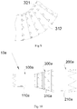
- the covering film includes a first covering film 110 disposed on the first section 100, a second covering film 210 disposed on the second section 200, and a third covering film 310 disposed on the transition section 300.
- the bare stent includes a first radial supporting structure 120 disposed on the first section 100, a second radial supporting structure 220 disposed on the second section 200, and a third radial supporting structure 320 disposed on the transition section 300, where the first radial supporting structure 120 is connected with the first covering film 110, and the second radial supporting structure 220 is connected with the second covering film 210, and the third radial supporting structure 320 is connected with the third covering film 310.
- the first radial supporting structure 120 is woven in a two-layer weaving manner.
- the first radial supporting structure 120 includes a mesh structure formed by connecting a number of first wavy rings 121 in the axial direction.
- Each of the first wavy rings 121 includes 5-20 crests and troughs (i.e., the first wavy ring 121 includes 5-20 crests and 5-20 troughs, with the number of crests and troughs being the same), and a wave height (referring to a vertical height between two adjacent crest and trough of the first wavy ring) of the first wavy ring is 2-5 mm.
- the number of first wavy rings 121 are arranged in several rows in the axial direction. Each row includes two first wavy rings 121 arranged side by side, in which a number of crests of one first wavy ring 121 correspond one-to-one with a number of troughs of the other wavy ring 121, and a number of rod bodies of one wavy ring 121 are respectively laminated one by one with a number of rod bodies of the other wavy ring 121, so that the two first wavy rings 121 form a number of quadrangles.
- the crests and troughs of two adjacent rows of the first wavy rings 121 are oppositely arranged, and they are mutually buckled to form an interlocking structure, such that the two adjacent rows of the first wavy rings 121 can get close to each other but cannot get far away from each other, so that the elongation ratio of the first section 100 is effectively controlled, and the axial elongation capacity of the first section 100 when the first section 100 is subjected to external force can be reduced, thereby reducing the risk of inaccurate positioning of the first section 100 upon release.
- the interlocking structure is formed in such a manner that wires forming portions of the crests 1211 of the first wavy rings 121 of the right one of the two adjacent rows of the first wavy rings 121 firstly pass over wires forming portions of the troughs 1212 of the first wavy rings 121 of the left one of the two adjacent rows of the first wavy rings 121 so that the wires of the crests and troughs of every two adjacent first wavy rings 121 of the two rows of the first wavy rings 121 are hooked together.
- first radial supporting structure 120 may also be formed in a three or more layer weaving manner, i.e., each row includes three or more first wavy rings 121 arranged side by side.
- the second radial supporting structure 220 is formed in a single-layer weaving manner.
- a mesh structure of the second radial supporting structure 220 has a greater pore diameter than a mesh structure of the first radial supporting structure 220.
- the second radial supporting structure 220 includes a mesh structure formed by connecting a number of second wavy rings 221 in the axial direction. For example, the crests and the troughs of the two adjacent second wavy rings 221 are arranged opposite to each other, and are buckled with each other to form an interlocking structure.
- the first wavy rings 121 and the second wavy rings 221 are identical in shape, that is, the numbers of crests and troughs, and the angle between the wave height and a rod body of the second wavy ring 221 are the same as those of the first wavy ring 221, respectively, under which condition, since the weaving density of the second radial supporting structure 220 is less than that of the first radial supporting structure 120 and the pore diameter of the mesh structure of the second radial supporting structure 220 is greater than that of the mesh structure of the first radial supporting structure, the radial supporting strength of the second radial supporting structure 220 is less than that of the first radial supporting structure 120, thereby preventing the proximal end of the tube stent 10 from being compressed and deformed by the aortic stent, and reducing the compression on a branch blood vessel wall by the distal end of the tube stent 10.
- the third radial supporting structure 320 includes a number of third wavy rings 321 sequentially arranged in the axial direction of the first tube body 101, and two adjacent third wavy rings 321 are independent from each other and are not in contact with each other.
- the spacing between the two adjacent third wavy rings 321 i.e., the distance in the axial direction of the transition section 300 between the trough of one third wavy ring 321 and the crest of the other third wavy ring 321 of the two adjacent third wavy rings 321 is equal.
- the spacing between two adjacent third wavy rings 321 is less than the wave height of the third wavy ring 321.
- the spacing between two adjacent third wavy rings 321 is 1-4 mm, and the wave height of the third wavy ring 321 is 2-5 mm.
- the third wavy ring 321 is identical in shape with the first wavy ring 121 or the second wavy ring 221. It can be appreciated that the spacing and the wave height of the third wavy ring can also be adjusted according to the desired shortening ratio of the transition section 300.
- the first covering film 110 includes a first inner film 111 and a number of first outer films 112 attached to the first inner film 111, and the first radial supporting structure 120 is positioned between the first inner film 111 and the number of first outer films 112.
- the first inner film 111 is of a long cylindrical structure and the first outer films 112 are of short cylindrical structures, i.e., the length of the first inner film 111 in the axial direction of the first radial supporting structure 120 is greater than the lengths of the first outer films 112 in the axial direction of the first radial supporting structure 120, and the first inner film 111 covers an inner wall of the radial supporting structure 121 of the entire first section 100 to isolate the blood flow.
- the first wavy rings 121 of the first radial supporting structure 120 are sandwiched between the first inner film 111 and the number of first outer films 112 except for the positions of crests and troughs. That is, the entire first inner film 111 covers the inner side of the first radial supporting structure 120, and each first outer film 112 covers middle areas of a row of the first wavy rings 121 except for the positions of crests and troughs. That is, the crest and trough of each of the first wavy rings 121 are exposed, and the other positions are covered by the first inner film 111 and the first outer film 112.
- the crests of each of the first wave-shaped rings 121 can be separated from the first inner film 111 and the first outer film 112 (that is, the crests of each of the first wavy rings 121 can be tilted with respect to the first inner film 111 and the first outer films 112), and the characteristic that the two adjacent first wavy rings 121 in the first radial supporting structure 120 are close to each other can be exerted, thereby improving the flexibility of the first section 100.
- the second covering film 210 includes a second inner film 211 and a second outer film 212 attached to the second inner film 211, the second radial supporting structure 220 is located between the second inner film 211 and the second outer film 212, the second inner film 211 and the second outer film 212 are of long cylindrical structures, and the lengths of the second inner film 211 and the second outer film in the axial direction of the second radial supporting structure 221 are equal to the axial length of the second section 200, so that all second wavy rings 221 of the second radial supporting structure 220 are sandwiched between the second inner film 211 and the second outer film 212.
- the third covering film 310 includes a third inner film 311 and a number of third outer films 312 attached to the third inner film 311, the third radial supporting structure 320 is located between the third inner film 311 and the number of third outer films 312, and two ends of the third inner film 311 are connected with the first inner film 111 and the second inner film 211, respectively.
- the third inner film 311 is of a long cylindrical structure and the third outer films 312 are of short cylindrical structures, i.e. the length of the third inner film 311 in the axial direction of the third radial supporting structure 320 is greater than the lengths of the third outer films in the axial direction of the third radial supporting structure 320.
- Each third wavy ring 321 is sandwiched between a third inner film 311 and a third outer film 312, the crests of each third wavy ring 321 are exposed, and the troughs of each third wavy ring 321 are covered by the corresponding third outer film 312 and third inner film 311.
- the entire third inner film 311 covers the inner side of the third radial supporting structure 320
- one end of each third outer film 312 is disposed on the outer side of the corresponding third wavy ring 321, and the other end of the third outer film 312 extends to the inner side of the adjacent third wavy ring 321.
- each third outer film 312 covers a 1/2 area of the outer side of its corresponding third wavy ring 321, i.e., each third outer film 312 covers from a middle position of the third wavy ring 321 on the inner side of the third outer film 312.
- the crests or troughs of each third wavy ring 321 can be separated from the third outer films 312 and the third inner film 311 (that is, the crests or troughs of each third wavy ring 321 can be titled relative to the third outer films 312 and the third inner film), such that when the transition section is bent, on a slightly bent side, in the two adjacent wavy rings 321, one third wavy ring 321 can be overlaid with another third wavy ring 321, so that the transition section 300 has a good bending property and is able to conform to the anatomical form of the blood vessel, and the transition section 300 is easily shortened and can better absorb the vibration and displacement transmitted by the first section 100, thereby ensuring that the second section 200 remains relatively stationary with respect to
- the slightly bent side refers to a side where the bending radius is small when the transition section 300 is bent.
- the crests of the slightly bent side are exposed outside, the crests of the slightly bent side do not easily penetrate through the third inner film 311 in a bending process, and the service life of the transition section 300 is prolonged.
- the first inner film 111, the second inner film 211 and the third inner film 311 are integrally formed. That is, the first inner film 111, the second inner film 211 and the third inner film 311 are identical in material and size, and the first inner film 111, the second inner film 211 and the third inner film 311 are sequentially connected in the axial direction of the first tube body 101 to form a cylindrical structure.
- the tube stent 10 when the radial length of the first section 100 is compressed by 50%, the radial supporting strength is 0.25N/cm to 5N/cm, so that the first section 100 is prevented from being compressed and deformed by the aortic stent when being in contact with the aortic stent, the sufficient supply of the blood flow to the branch blood vessel is effectively ensured.
- the first section 100 has certain flexibility and shortening resistance, so that the first section 100 can conform more closely to the aortic wall and the aortic stent upon release, and the possibility of the risk that the opening of the tube stent 10 is covered by the aortic stent due to the retraction of the proximal end of the tube stent 10 caused by the flushing of the blood flow is low.
- the radial supporting strength of the second section 200 is less than the radial supporting strength of the first section 100, so that the distal end of the tube stent 10 is well anchored within the branch blood vessel and the stimulation of the second section 200 to the vessel wall can be controlled.
- the transition section 300 has a better bending property and shortening property, so that the tube stent 10 can conform to various types of chimney operation methods and branch blood vessel approach anatomical forms, especially when used in the aortic arch, the aortic pulsation can be buffered by the transition section 300, and the vibration deformation of the tube stent 10 stays at the first section 100 and the transition section 300, thereby ensuring the relative stability of the second section 200 and the branch blood vessel, and reducing the stimulation to the branch blood vessel wall.
- a tube stent 10a according to a second embodiment is mainly used for a branch blood vessel of a renal artery.
- a renal artery chimney technology mostly adopts a two-chimney technology.
- the tube diameter of a first section 100a is less than that of a second section 200a
- the transition section 300 is a tapered transition, that is, the transition section 300 is connected between the first section 100a and the second section 200a, and is of a truncated conical structure.
- structures of a first radial supporting structure 120a, a second radial supporting structure 220a and a third radial supporting structure 320a are similar to that of the second radial supporting structure 220 in Embodiment 1. That is, the first radial supporting structure 120a, the second radial supporting structure 220a and the third radial supporting structure 300a are woven using a single-layer weaving method. For example, a single-layer wave ring structure woven from a single nickel-titanium wire is used.
- a mesh structure of the first radial supporting structure 120a has a smaller pore diameter than a mesh structure of the second radial supporting structure 220a.
- a first covering film 110a and a second covering film 210a are the same in film covering method, and cover in the same manner as the second covering film 210 of the second section 200 in Embodiment 1, that is, the first covering film also includes a first inner film and a second outer film attached to the first inner film, the first inner film and the first outer film are also of long cylindrical structures, the axial lengths of the first inner film and the first outer film are equal to the axial length of the first section, the first wavy rings 121a are wrapped between the first inner film and the second outer film, and the second wavy rings 221a are wrapped between the second inner film and the second outer film.
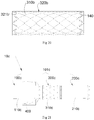
- the number of third outer films 312a is plural, and the third outer films 312a can cover rod bodies of third wavy rings 321a in circumferential directions of the third wavy rings 321a and expose the crests and troughs of the third wavy rings 321a. That is, each third outer film 312a covers middle areas of one row of third wavy rings 321a except for positions of the crests and the troughs. That is, the crests and toughs of each third wavy ring 321a are exposed, and the other positions of the third wavy ring 321a are covered by the third outer films 312a.
- the widths of the portions of the third outer films 321a in the circumferential directions are equal so that the transition section 300a can be bent in all directions to adapt to different vessel forms.
- the widths of the third outer films 312a in the axial direction of the transition section 300a are greater than or equal to 1/5 of the distance in the axial direction of the transition section 300a between the crest and the trough of the third wavy ring 321a clamped by the third outer films 312a, and less than or equal to 4/5 of the distance in the axial direction of the transition section 300a between the crest and trough of the third wavy ring 321a clamped by the third outer films 312a so as to ensure that no third wavy rings 321a clamped by the third outer films 312a can be separated from the covering films while the crests and troughs of the first wavy ring 321a can be exposed.
- the widths of the third outer films 312a in the axial direction of the transition section 300a are equal to 1/2 of the distances in the axial direction of the transition section 300a between the crests and the troughs of the third wavy rings 321a clamped by the third outer films 312a so as to ensure that the transition section 300a has the better bending property and shortening property, and the structure of the transition section 300a can be stabilized.
- the third outer films 312a may also cover the third wavy rings 321a in other directions along the third wavy rings 321a. Referring to FIG.
- the angle between the extension direction of each third outer film 312a and the axial direction of the transition section 300a is not greater than 65°, so that the movable distance between the third wavy rings 321a is large, thereby improving the flexibility of the transition section 300a.
- the angle between the extension direction of each third outer film 312a and the axial direction of the transition section 300a is 30° to 60°.
- the angle between the extension direction of each third outer film 312a and the extension direction of the covered rod body is 90° ⁇ 20°, so as to help the third outer film 312a cover as many third wavy rings as possible without changing the extension direction, thereby facilitating the film covering and the improvement of the production efficiency.
- each third outer film 312a covers all of the third wavy rings 321a, that is, each third outer film 312a extends from the first third wavy ring 321a to the last third wavy ring 321a, the third outer film 312a covers at least one rod body of each third wavy ring 321a, and each third outer film 312a covers a longer area, so that the binding force between each third outer film 312a and the third inner film can be increased, the probability that the third outer film 312a is loosened can be reduced, the number of the third outer films 312a can be reduced, the difficulty of a film covering process is reduced, and the production efficiency is improved.
- the third outer film 312a is pulled from the rod body position of the first third wavy ring 321a toward the rod body of the second third wavy ring 321a, and then toward the rod body of the third wavy ring 321a until the rod body of the last third wavy ring 321a so as to complete the film covering in one extension direction, then the film covering in a second extension direction is performed in the same manner, so that all rods bodies of all the third wavy rings 321a are covered with the third outer films 312a.
- the widths of the portions of the third outer films 312a are equal, and the widths of the third outer films 312a are 1/3 to 1/2 of the lengths of the rod bodies of the third wavy rings 321a, so that the requirements that the shortening ratio of the transition section 300a is between 30% and 50%, and the bending radius of the transition section 300a is less than 5mm are met.
- the number of rod bodies covered by the third outer films 321a and the widths of the third outer films 321a may be adjusted accordingly to meet the required shortening ratio and bending radius of the transition section 300a.
- the third outer films 312a may cover only portions of the rod bodies or the widths of the number of third outer films 312a may be not exactly the same.
- the third inner film and the third outer film 312a may take other forms as well, for example, the third outer film 312a may be in the form of an integral film covering all of the third wavy rings 321a on outer surfaces of the third wavy rings 321a, the third inner film is of a strip structure covering the third wavy rings 321a only on inner surfaces of the third wavy rings 321a, only covering two third wavy rings 321a at the head end and the tail end (i.e. the first third wavy ring 321a close to the first section and the last wavy ring 321a close to the second section).
- the first section 100a adopts a single-layer weaving method, the included angle between two adjacent side rods of the first wavy ring 121a is large, and an inner film and outer film integral film covering mode is adopted, so that the radial supporting strength of the first section 100a is large, thereby ensuring that the first section 100a can be prevented from being compressed and deformed when being released in parallel with the abdominal aortic covered stent.
- the transition section 300a has a better bending property and shortening property, a better release form of the tube stent 10a can be ensured, and the influence of arterial pulsation on the second section 200a can also be eliminated.
- the included angle between two adjacent side rods of the second wavy ring 221a in the second section 200a is small, so that the second section 200a has small radial supporting strength; meanwhile, the second section 200a adopts the inner film and outer film integral film covering method, so that the second section 200a has high shorting resistance, thereby effectively improving the wall attaching property and stability of the second section 200a.
- the overall uniformity of the tube stent 10a is good, and uniform assembly and release of the tube stent 10a are facilitated.
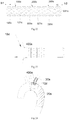
- a bare stent of a tube stent 10b of a third embodiment is cut with a nickel-titanium tube, and covered with a single-layer film covering structure including only an inner film, for example, a PET inner film, to which the bare stent is fixed by sutures 140.
- a first radial supporting structure 120b of a first section 100b is integrally cut and includes a mesh structure formed by connecting a number of first wavy rings 121b in the axial direction, so that the first section 100b is high in radial supporting strength and is not prone to bending deformation.
- the first wavy ring 121b includes 5 to 20 crests and troughs.
- a through hole 123 for sewing with a first covering film 110b is arranged at a connecting part of the crest of one first wavy ring 121b and the trough of the other wavy ring 121b.
- a second radial supporting structure 220b of a second section 200b is likewise integrally cut and includes a number of connected second wavy rings 221b.
- the second radial supporting structure 220b includes a number of spaced apart second wavy rings 221b, where- the adjacent second wavy rings 221b are connected by a connecting rod 223.
- the number of the connecting rods 223 between the two adjacent second wavy rings 221b is 1 to 10, so that the stability of the second section 200b is effectively guaranteed, the shortening ratio of the second section 200b is reduced, and the risk of displacement when the second section 200b is anchored is reduced.
- the second wavy ring 221b includes 5-20 crests and troughs.
- positions of a portion of the crests of the second wavy ring 221b may also be provided with through holes 123 for sewing with a second covering film 210b.
- a third radial supporting structure 320b of a transition section 300b is formed with a number of independent third wavy rings 321b in a cutting manner.
- the third wavy ring 321b includes 5-20 crests and troughs.
- a phase difference between two adjacent third wavy rings 321b is zero, that is, a line connecting two nearest crests or two nearest troughs of the adjacent third wavy rings 321b is parallel to the axial direction of the transition section 300b.
- the spacing between two adjacent third wavy rings 321b is equal to 1/2 of the wave height of the third wavy ring 321b (the wave height refers to the vertical height between the crest and the trough of the third wavy ring 321b), in other words, the shortening ratio of the transition section 300b is 30%.
- a ratio of the spacing between the two adjacent third wavy rings 321b to the wave height of the third wavy ring 321b may be other values as long as it is ensured that the shortening ratio of the transition section 300b is not greater than 50%.
- each crest or trough position of the third wavy ring 321b is provided with a through hole 123 for sewing with a third covering film 310b.
- the numbers of the crests and troughs of the first wavy ring 121b, the second wavy ring 221b and the third wavy ring 321b are equal, and the included angle between the wave height of each wavy ring and a rod body is equal, so that the consistency is good.
- the first covering film 110b, the second covering film 210b and the third covering film 310b adopt integrally formed PET films, and the first radial supporting structure 120b, the second radial supporting structure 220b and the third radial supporting structure 320b are respectively fixed to the outer sides of the PET films by sutures. It can be appreciated that in other embodiments, the first radial supporting structure 120b, the second radial supporting structure 220b and the third radial supporting structure 320b may be fixed to the inner sides of the PET films by sutures, respectively. It can also be appreciated that in other embodiments, the first covering film 110b, the second covering film 210b and the third covering film 310b may also adopt integrally formed PTFE films or other similar films.
- the transition section 300b includes a third radial supporting structure 320b and a third covering film 310b covering the third radial supporting structure 320b.
- the structure of the third radial supporting structure 320b may refer to the third radial supporting structure 320a in Embodiment 2, that is, the third radial supporting structure 320b includes a mesh structure formed by connecting a number of third wavy rings 321b in the axial direction, and the crests and troughs of two adjacent third wavy rings 321b are arranged opposite to each other and are buckled with each other to form an interlocking structure.
- the third covering film 310b is located on the outer side of the third radial supporting structure 320b (i.e., the third covering film 310 includes only an outer film and no inner film), only two third wavy rings 321b at the head and the end of the third radial supporting structure 320b are fixedly connected with the third covering film 320b by sutures 140, and the third wavy ring 321b in the middle is not fixed to the third covering film 310b.
- third wavy rings 321b may be fixed to the third covering film 310b by sutures as desired, for example, a number of third wavy rings 321b at the ends may be fixed to the third covering film 310b by sutures, leaving only a small portion of the third wavy rings 321b not connected with the third covering film 310b.
- a tube stent 10c of a fourth embodiment further includes a second tube body 400 sleeving a first tube body 101c, and one end of the second tube body 400 is in sealing connection with the outer surface of the first tube body 101c.
- the second tube body 400 is positioned at a first section 100c, with an opening of the second tube body 400 facing one end of the first tube body 101c far away from the second section.
- the second tube body 400 can block a gap formed by the matching of the tube stent 10c and an aortic covered stent, thereby effectively preventing type I endoleak.
- the length of the second tube body 400 is less than that of the first section 100c.
- one end of the first section 100c far away from the second section 200c extends beyond an open end of the second tube body 400.
- the end of the first section 100c far away from the second section 200c extends beyond the open end of the second tube body 400 by 10-15 mm, so that the tube stent 10c is better matched with the aortic covered stent, avoiding the occurrence of type I endoleak.
- a first radial supporting structure 120c, a second radial supporting structure 220c and a third radial supporting structure 300c are woven in a single-layer weaving method.
- a single-layer wave ring structure woven from a single nickel-titanium wire is used. That is, structures of the first radial supporting structure 120c, the second radial supporting structure 220c and the third radial supporting structure 320c are similar to that of the second radial supporting structure 220 in Embodiment 1.
- the numbers of crests and troughs of the first wavy rings 121c, the second wavy rings 221c and the third wavy rings 321c are the same, and the wave heights h1 of the first wavy rings 121c and third wavy rings 321c are equal and are less than the wave heights h2 of the second wavy rings 221c, so that the radial supporting strength of the first section 100c is greater than that of the second section 200c.
- film covering methods of a first covering film 110c, a second covering film 210c and a third covering film 310c are the same as those of the corresponding portions in Embodiment 2, and thus will not be described in detail herein.
- the radial supporting strength of the second tube body 400 is less than that of the first section.
- a supporting structure of the second tube body 400 employs a nickel-titanium wire having a smaller wire diameter under the same other conditions.
- the first tube body employs a nickel-titanium wire having a wire diameter of 0.0060-0.0080 inches
- the second tube body 400 employs a nickel-titanium wire having a wire diameter of 0.0045-0.0059 inches.
- the second tube body 400 may adopt the same film covering method, namely the inner film and outer film integral film covering method, as the first section 100c, so that the second tube body 400 has relatively high shorting resistance and low flexibility, and the second tube body 400 is thus prevented from being displaced in the filling gap.
- a thickness of the covering film of the second tube body 400 is less than that of the covering film of the first section 100c to facilitate the loading of the tube stent 10c into a sheath tube and reduction of an inner diameter of the sheath tube required for containing the sheath.
- the second tube body 400 is arranged at the periphery of the first tube body 101c, and the radial supporting strength of the second tube body 400 is less than that of the first tube body, so that the tube stent 10 is prevented from further compressing the artery covered stent in an extrusion process with the artery covered stent, to further avoid the increase of the gap between the tube stent 10c and the artery covered stent and at the same time better fill the gap between the tube stent 10c and the artery covered stent, thereby effectively preventing internal hemorrhage.
- a tube stent 10d of a fifth embodiment is different from that of Embodiment 4 in that the second tube body 400a can be outwardly bent.
- the tube stent 10d corresponds to another release form, and after a main stent 20 is fenestrated, a proximal end of the tube stent 10d is anchored to a lumen of the main stent 20a through a window, and a distal end of the tube stent 10d is located outside the main stent 20a and anchored in a branch blood vessel 30a.
- the second tube body 400a is turned outwards and attached to the inner side of the main stent 20a to prevent a blood flow from leaking from the window position of the main stent 20a.
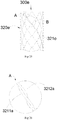
- a third radial supporting structure 320e of a transition section 300e of a tube stent of a sixth embodiment is continuously woven with a single wire.
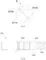
- the third radial supporting structure 320e includes a number of third wavy rings 321e sequentially arranged in the axial direction, the number of third wavy rings are connected in the axial direction to form a mesh structure, crests and troughs of two adjacent third wavy rings 321e are arranged opposite to each other and are mutually buckled to form an interlocking structure, the number of third wavy rings 321e are woven from the first third wavy ring 321e to the last third wavy ring 321e of the transition section 300e by a same metal wire, and the wire head and the wire tail of at least one the third wavy ring 321e are wound no more than twice and span to the next third wavy ring 321e.
- a wire head 321a and a wire tail 3212a of the first third wavy ring 321e of the transition section 300e are fixed by a number of times of winding as seen from the top down, after the first wavy ring 321e is woven, the wire tail 321a of the first wavy ring 321e obliquely spans to the second third wavy ring 321e in the direction of the wire head 321a, and acts as a wire head 3211b of the second third wavy ring 321e to undergo the weaving of the second third wavy ring 321e, after the second third wavy ring 321e is woven, a wire tail 3212b presses the wire head 321b to improve the stability of the structure, that is, the wire head 3211b and the wire tail 3212b are wound (inserted) by one time, then the wire tail 3212b obliquely spans to the third wavy ring 321e in the direction
- the flexibility of the transition section 300e can be improved advantageously.
- the single wire is adopted for continuous weaving, and the whole transition section 300e is only provided with two ends of the wire head and the wire tail, thereby reducing the influence of the wire head and the wire tail on the vessel wall to a great extent.
- the wire heads and the wire tails of the first and last third wavy rings 321e are fixed through a number of times of winding
- the wire heads and the wire tails of the other third wavy rings 321e can be wound (inserted) by one or two times to ensure the stability of the wire heads and the wire tails.
- the third wavy rings 321e of the transition section 300e are not so limited, e.g., the wire head and tail of the first third wavy ring 321e may be fixed by winding, the wire head and tail of the second third wavy ring 321e may be wound only one time, and the wire head and wire tail of the third wavy ring 321e may be wound at least two times, and the number of winding times may be adjusted according to the required flexibility of the transition section 300e.
- the third radial supporting structure 320e of the transition section 300e may also employ a number of metal wires to form a corresponding multi-layer woven structure, such as two metal wires to form a double-layer woven structure, which is similar to the first radial supporting structure of Embodiment 1.
- the diameter of the end, close to a transition section 300f, of a second section 200f of a tube stent 10f of Embodiment 7 is greater than that of the end, far away from the transition section 300f, of the second section 200f.
- the second section 200f is a frustum-shaped structure, and a difference value between the diameter of the end, close to the transition section 300f, of the second section 200f and the diameter of the end, far away from the transition section 300f, of the second section 200f is 1-3 mm to better conform to the anatomical form of the branch blood vessel.
- a second covering film 210f at the end, far away from the transition section 300f, of the second section 200f is provided with a hollow structure, and the hollow structure is located in an area where the second covering film 210f is not in contact with a second supporting structure (not shown), that is, the second covering film 220f is hollowed out on the second covering film 210f along the pattern of the second supporting structure, so that a distal end of the tube stent 10f can be prevented from shielding a branch blood vessel.
- a number of diamond-shaped hollow structures are provided on the covering film at the end, far away from the transition section 300f, of the second section 200f, and the number of diamond-shaped hollow structures are uniformly distributed in the circumferential direction.
- the hollow structure arranged at the end, far away from the transition section 300f, of the second section 200f is 12-18 mm in length, for example 15 mm in length.
- an area on the second covering film 210f where the hollow structure is provided cover three second wavy rings 221f.
- the hollow structure can be arranged as desired, for example, the hollow structure can also be selectively arranged at certain specific locations without covering the entire circumferential direction, and the hollow area can also be non-uniformly distributed in the circumferential direction.
- the end, far away from the transition section 300f, of the second section 200f may not be provided with the second covering film 210f.
- a second section 200g of a tube stent 10g of an eighth embodiment includes a connecting section 2001g, a tapered section 2002g and a distal section 2003g, two ends of the tapered section 2002g are connected with the connecting section 2001g and the distal section 2003g, respectively.
- the end, far away from the tapered section 2002g, of the connecting section 2001g is connected with a transition section 300g.
- the diameter of the end, close to the connecting section 2001g, of the tapered section 2002g is greater than the diameter of one end, close to the distal section 2001g, of tapered section 2002g.
- the end, close to the connecting section 2001g, of the tapered section 2002g, the connecting section 2001g and the transition section 300g are equal in diameter
- the diameter of the distal section 2003g is equal to that of the end, far away from the connecting section 2001g, of the tapered section 2002g
- the diameter of the distal section 2003g is 1/3 to 3/4 of the diameter of the connecting section 2001g.
- the taper section 2002g is provided with a hollow structure.
- the diameter of the distal section 2003g is 1/2 the diameter of connecting section 2001g.
- the hollow structure of the tapered section 2002g can effectively ensure the patency of the blood flow of a left common carotid artery 23, and the diameter difference between the connecting section 2001g and the distal section 2003g enables the tube stent 10g to be well attached to the right subclavian artery 22 on the premise of less stimulation to the vessel wall, thereby preventing the tube stent 100g from being displaced.
- first radial supporting structure, the second radial supporting structure, the third radial supporting structure, the first covering film, the second covering film, and the third covering film are not limited to the structures employed in the embodiments described above. Other structures may also be used where conditions are met. Furthermore, the first radial supporting structure, the second radial supporting structure and the third radial supporting structure in each embodiment are not uniquely fixed to the first covering film, the second covering film and the third covering film. Mutual combination and collocation can be carried out when conditions are met.
- the first radial supporting structure in Embodiment 1 may employ the first covering structure in Embodiment 1 or the first covering structure in Embodiment 2.
Landscapes
- Health & Medical Sciences (AREA)
- Engineering & Computer Science (AREA)
- Biomedical Technology (AREA)
- Heart & Thoracic Surgery (AREA)
- Public Health (AREA)
- Transplantation (AREA)
- Cardiology (AREA)
- Veterinary Medicine (AREA)
- Oral & Maxillofacial Surgery (AREA)
- Vascular Medicine (AREA)
- Life Sciences & Earth Sciences (AREA)
- Animal Behavior & Ethology (AREA)
- General Health & Medical Sciences (AREA)
- Gastroenterology & Hepatology (AREA)
- Pulmonology (AREA)
- Physics & Mathematics (AREA)
- Optics & Photonics (AREA)
- Prostheses (AREA)
Abstract
Description
- Embodiments relate to the field of interventional medical instruments, in particular to a tube stent.
- In the field of treatment of intra-aortic diseases, when an interlayer breach is too close to a branch blood vessel, insufficient anchoring force of an aortic covered stent is easily caused, and a chimney technology or an in-situ windowing technology is generally needed to achieve the purposes of isolating a lesion position and opening the branch blood vessel. Referring to
FIG. 1 , the chimney technology is such that an aortic coveredstent 11 is placed in an aortic lumen and passes over and covers an opening of abranch blood vessel 12 while abranch stent 13 is released in the aortic lumen close to a proximal end of the aortic coveredstent 11, so that the proximal end of thebranch stent 13 enters the aortic lumen and a distal end of thebranch stent 13 enters thebranch blood vessel 12, thereby ensuring the blood supply for thebranch blood vessel 12. It should be noted that after the stent is implanted into the blood vessel, a blood flow flows from the proximal end of the stent to the distal end of the stent. - A branch stent adopted in the existing chimney technology, however, generally adopts a single raw material specification, and all parts of the branch stent have the same or similar physical properties through a unified processing technology. Although such a stent has good consistency, due to high radial supporting strength of the aortic covered stent, when the branch stent and the aortic covered stent are positioned in the aortic lumen together, the aortic covered stent can generate high squeezing force on the proximal end of the branch stent, and the proximal end of the branch stent has a poor form after being pressed and is easy to deform and even can cause an opening of the proximal end of the branch stent to be completely closed. In addition, when an aortic arch is subjected to the chimney technology, a position, size and form of a blood vessel of the arch part are changed periodically according to the pulsation of blood, the proximal end of the branch stent is attached to the wall of an aorta and thus also moves along with the pulsation of the aorta, while the distal end of the branch stent needs to be attached to the branch blood vessel, and the movement of the branch stent can cause stimulation to the wall of the branch blood vessel and even damage to a branch blood vessel wall. In addition, in the aortic arch, the central axis of the branch blood vessel close to the opening of the aorta and the central axis of the aorta usually form an included angle of 90° or close to 90°, and the branch stent is required to be capable of conforming to the bending of the blood vessel when the chimney technology is carried out. However, the current branch stent is prone to folding or narrowing at a connecting part between the aortic lumen and the branch blood vessel, which affects the patency of the blood flow in the branch blood vessel.
- On such basis, it is desired to provide a tube stent to solve at least one of the above-mentioned technical problems.
- A tube stent includes a first tube body, and the first tube body includes a first section, a second section and a transition section which is positioned between the first section and the second section, one end of the transition section is connected with the first section, the other end of the transition section is connected with the second section, and shortening rates of the first section and the second section are less than a shortening ratio of the transition section.
- According to the tube stent, a shortening ratio of the transition section is greater than those of the first section and the second section, and the pulsation of an aorta can be buffered by the transition section, so that the vibration deformation of the tube stent stays at the first section and the transition section, thereby ensuring the relative stability of the second section and a branch blood vessel, and reducing the stimulation to the branch blood vessel wall. Moreover, the first section can be more attached to the aorta wall and an aortic covered stent when released, the possibility of the risk that an opening of the tube stent is covered by the aortic covered stent due to the retraction of a proximal end of the tube stent caused by the flushing of a blood flow is low, and the second section can ensure that a distal end of the tube stent is well anchored in the branch blood vessel.
-
-
FIG. 1 is a schematic structural view of an aortic covered stent after being implanted into a lumen with a branch stent based on a chimney technology in the prior art; -
FIG. 2 is a schematic structural view of a tube stent according to a first embodiment; -
FIG. 3 is a schematic structural view of the tube stent shown inFIG. 2 after being implanted into the lumen with the aortic stent; -
FIG. 4 is a schematic structural view of a bare stent of the tube stent shown inFIG. 2 ; -
FIG. 5 is a schematic structural view of a first radial supporting structure of a first section ofFIG. 4 ; -
FIG. 6 is a partial schematic structural view of a first covering film of a first section ofFIG. 2 matched with the first radial supporting structure; -
FIG. 7 is a partial schematic structural view of a second covering film of a second section ofFIG. 2 matched with a second radial supporting structure; -
FIG. 8 is a partial schematic structural view of a third covering film of a transition section ofFIG. 2 matched with a third radial supporting structure; -
FIG. 9 is a schematic structural view of the transition section ofFIG. 8 after being bent; -
FIG. 10 is a schematic structural view of a tube stent according to a second embodiment; -
FIG. 11 is a schematic structural view of a bare stent of the tube stent ofFIG. 10 ; -
FIG. 12 is a schematic structural view of a first wavy ring or a third wavy ring ofFIG. 11 ; -
FIG. 13 is a schematic structural view of a second wavy ring ofFIG. 11 ; -
FIG. 14 is a partial schematic structural view of a third covering film of a transition section ofFIG. 10 matched with the third radial supporting structure; -
FIG. 15 is a partial schematic structural view of a third covering film of a transition section in another embodiment matched with the third radial supporting structure; -
FIG. 16 is a schematic structural view of a tube stent according to a third embodiment; -
FIG. 17 is a partial schematic structural view of a first radial supporting structure of a first section ofFIG. 16 ; -
FIG. 18 is a partial schematic structural view of a second radial supporting structure of a second section ofFIG. 16 ; -
FIG. 19 is a partial schematic structural view of a third radial supporting structure of a transition section ofFIG. 16 ; -
FIG. 20 is a schematic structural view of a transition section in another embodiment; -
FIG. 21 is a schematic structural view of a tube stent according to a fourth embodiment; -
FIG. 22 is a schematic structural view of a bare stent of the tube stent ofFIG. 21 ; -
FIG. 23 is a schematic structural view of a tube stent according to a fifth embodiment; -
FIG. 24 is a schematic structural view of the tube stent ofFIG. 23 implanted into a lumen in cooperation with a main stent. -
FIG. 25 is a schematic structural view of a transition section according to a sixth embodiment without being covered; -
FIG. 26 is an enlarged view of a portion A ofFIG. 25 ; -
FIG. 27 is an enlarged view of a portion B ofFIG. 25 ; -
FIG. 28 is a schematic structural view of a tube stent according to a seventh embodiment; -
FIG. 29 is a schematic structural view of a tube stent according to an eighth embodiment; -
FIG. 30 is a schematic structural view of the tube stent shown inFIG. 29 after implantation into a blood vessel. - In order to make the purposes, technical solutions, and advantages of the present application more fully apparent, further details are set forth with reference to the accompanying drawings and embodiments. It can be appreciated that the embodiments described herein are merely illustrative and are not intended to be limiting.
- In the field of tube stents, a blood flow is defined from a proximal end of a tube stent to a distal end of the tube stent after the tube stent is implanted into a blood vessel. Hereinafter, technical solutions will be described in further detail with reference to exemplary embodiments.
- Referring to
FIG. 2 , atube stent 10 according to an embodiment may be used as a branch stent for a chimney technology, for example, placed in an arterial lumen together with an aortic covered stent. Thetube stent 10 includes afirst tube body 101, where thefirst tube body 101 includes afirst section 100, asecond section 200 and atransition section 300 which is positioned between thefirst section 100 and thesecond section 200. One end of thetransition section 300 is connected with thefirst section 100, the other end of thetransition section 300 is connected with the second section. Thefirst section 100, thesecond section 200 and thetransition section 300 are of hollow tubular structures. Referring toFIG. 3 , after release, thefirst section 100 is adapted to be placed in an aortic lumen together with the aortic coveredstent 20, thesecond section 200 is adapted to be anchored in abranch blood vessel 30, and thetransition section 300 connects thefirst section 100 and thesecond section 200 such that thetube stent 10 completes a transition from an aorta to the branch blood vessel by bending deformation of thetransition section 300. In one embodiment, the end of thefirst section 100 is not closer to the branch blood vessel than the end of the aortic coveredstent 20. In another embodiment, the end of thefirst section 100 is further away from the branch blood vessel than the end of the aortic coveredstent 20, i.e., thefirst section 100 extends beyond the end of the aortic coveredstent 20, to prevent a situation that a blood flow cannot enter the branch blood vessel through thefirst section 100 since an opening of thefirst section 100 is covered by the aortic covered stent and shielded. For example, a length of thefirst section 100 is not less than 10 mm. In the present embodiment, the length of thefirst section 100 is not less than 15 mm. The length of thesecond section 200 is not greater than 40 mm because poor flexibility of thetube stent 10 as a whole is easily caused if the length of thesecond section 200 is more than 40 mm. In a natural state, the axial length of thetransition section 300 is not greater than 3/4 of the total length of thefirst tube body 101 because, if the length of thetransition section 300 exceeds 3/4 of the total length of thetube stent 10, an overall shortening ratio of thetube stent 10 is high, which easily causes displacement of thetube stent 10 upon release. - Further, the radial supporting strength of the
first section 100 is greater than the radial supporting strength of thesecond section 200. For example, when the radial length of thefirst section 100 is compressed by 50%, the radial supporting strength of thefirst section 100 is 0.25 N/cm to 5 N/cm, making it difficult for thetube stent 10 to be compressed and deformed in an area where the tube stent is released in parallel with the aortic covered stent, thereby effectively ensuring the supply of the blood flow into the branch blood vessel. In one embodiment, when the radial length of thefirst section 100 is compressed by 50%, the radial supporting strength of thefirst section 100 is 0.4 N/cm to 5 N/cm. In this present embodiment, when the radial length of thefirst section 100 is compressed by 50%, the radial supporting strength of thefirst section 100 is 1 N/cm to 3 N/cm. When the radial length of thesecond section 200 is compressed by 50%, the radial supporting strength of thesecond section 200 is 0.1 N/cm to 1 N/cm. - A radial supporting force can be tested by a flat plate extrusion method, and then the radial supporting strength is calculated with the radial supporting force. For example, the
first section 100 is clamped in a tangential direction along the circumference of the first radial supporting structure using two parallel flat plates, with one fixed flat plate fixed to a base and one movable flat plate placed above thefirst section 100, the two flat plates are always kept parallel during testing, and a radial force is applied to the movable flat plate to test the magnitude of the radial force when the first radial supporting structure is compressed from the original radial length to 50% reduction. The radial supporting strength is equal to the radial force divided by the length of thefirst section 100. - Further, the flat plate extrusion method described above is only one exemplary testing method and is not intended to limit the present application, and any suitable method may be used by one of ordinary skill in the art to perform an equivalent test to the flat plate extrusion method.
- In one embodiment, the shortening ratio of the
first section 100 is not greater than 10% to avoid thefirst section 100 from retracting under the impact of the blood flow and an opening of thefirst section 100 from being shielded by the aortic covered stent, thereby ensuring that the blood flow is able to enter the branch blood vessel from the opening of thefirst section 100. It is to be noted that, in the present application, the shortening ratio means a ratio of a difference value between L and L' to L, where, taking the first section as an example, L is the length of the first section in a natural state, and L' is the length of the first section in the axial direction of the first section remaining constant under the condition that when the two ends of the first section are simultaneously compressed by the force from the ends to the middle, the two ends of the first section draw close to the center middle in the axial direction of the first section, or one end of the first section draws close to the other end of the first section, the included angles between two end surfaces of the first section and the axial direction of the first section are the same as those in the natural state. Further, the shortening rates of thefirst section 100 and thesecond section 200 are less than that of thetransition section 300, so that thetube stent 10 can meet the requirement of flexibility to reduce the risk of displacement upon release. In one embodiment, the shortening ratio of thetransition section 300 is not less than 30%, so that vibration of the proximal end of thetube stent 10 due to fluctuation of the aortic stent can be effectively reduced or absorbed, and displacement of the proximal end of thetube stent 10 due to the vibration can be effectively avoided, thereby ensuring that thesecond section 200 is relatively stationary with the branch blood vessel and reducing the stimulation of thesecond section 200 to the branch blood vessel wall. In one embodiment, the shortening ratio of thetransition section 300 is not greater than 50% to reduce the risk of dislodging upon release of thetube stent 10. - Furthermore, a bending radius of the
transition section 300 is not greater than 10 mm, so that thetransition section 300 can adapt to various vessels in different forms and is well attached to the vessel wall, thetransition section 300 is prevented from folding or narrowing due to the fact that thetransition section 300 conforms to the form of the vessel, and the patency of the blood flow of the branch blood vessel is ensured. It is to be noted that the bending diameter of the transition section in the present application means the minimum radius that the transition section can reach under the condition that the variation of the radial length of each part of the transition section is less than 5% on the premise of ensuring the radial form of the transition section when the two ends of the transition section are bent towards the middle. In the present embodiment, the bending radius of thetransition section 300 is not greater than 5 mm. It can be noted that thetransition section 300 as an entirety may meet the requirements on the shortening ratio and the bending radius, where it is possible that the structure of thetransition section 300 may be uniform so that the structure may meet the requirements on the shortening ratio and the bending radius by modifying the structure of thetransition section 300. It also possible that thetransition section 300 may be divided into two parts, one part meeting the requirement on the bending radius and the other part meeting the requirement on the shortening ratio. For example, a portion of thetransition section 300 close to thefirst section 100 meets the requirement on the bending radius and the portion of thetransition section 300 close to thesecond section 200 meets the requirement on the shortening ratio. - Further, the radial length of the
first section 100 is not greater than that of thesecond section 200, so that the difficulty of sheathing thetube stent 10 can be reduced. In this embodiment, thefirst section 100, thesecond section 200 and thetransition section 300 are all equal in radial length. - The first tube body includes a covering film and a bare stent connected with the covering film. With continuing reference to
FIG. 2 , the covering film includes afirst covering film 110 disposed on thefirst section 100, asecond covering film 210 disposed on thesecond section 200, and athird covering film 310 disposed on thetransition section 300. Referring toFIG. 4 together, the bare stent includes a firstradial supporting structure 120 disposed on thefirst section 100, a secondradial supporting structure 220 disposed on thesecond section 200, and a thirdradial supporting structure 320 disposed on thetransition section 300, where the firstradial supporting structure 120 is connected with thefirst covering film 110, and the secondradial supporting structure 220 is connected with thesecond covering film 210, and the thirdradial supporting structure 320 is connected with thethird covering film 310. - With continuing reference to
FIG. 4 , the firstradial supporting structure 120 is woven in a two-layer weaving manner. In one embodiment, the firstradial supporting structure 120 includes a mesh structure formed by connecting a number of firstwavy rings 121 in the axial direction. Each of the first wavy rings 121 includes 5-20 crests and troughs (i.e., the firstwavy ring 121 includes 5-20 crests and 5-20 troughs, with the number of crests and troughs being the same), and a wave height (referring to a vertical height between two adjacent crest and trough of the first wavy ring) of the first wavy ring is 2-5 mm. The number of firstwavy rings 121 are arranged in several rows in the axial direction. Each row includes two first wavy rings 121 arranged side by side, in which a number of crests of one firstwavy ring 121 correspond one-to-one with a number of troughs of the otherwavy ring 121, and a number of rod bodies of onewavy ring 121 are respectively laminated one by one with a number of rod bodies of the otherwavy ring 121, so that the two first wavy rings 121 form a number of quadrangles. The crests and troughs of two adjacent rows of the first wavy rings 121 are oppositely arranged, and they are mutually buckled to form an interlocking structure, such that the two adjacent rows of the firstwavy rings 121 can get close to each other but cannot get far away from each other, so that the elongation ratio of thefirst section 100 is effectively controlled, and the axial elongation capacity of thefirst section 100 when thefirst section 100 is subjected to external force can be reduced, thereby reducing the risk of inaccurate positioning of thefirst section 100 upon release. Referring toFIG. 5 , the interlocking structure is formed in such a manner that wires forming portions of thecrests 1211 of the first wavy rings 121 of the right one of the two adjacent rows of the firstwavy rings 121 firstly pass over wires forming portions of thetroughs 1212 of the first wavy rings 121 of the left one of the two adjacent rows of the firstwavy rings 121 so that the wires of the crests and troughs of every two adjacent firstwavy rings 121 of the two rows of the first wavy rings 121 are hooked together. - It can be noted that in other embodiments, the first
radial supporting structure 120 may also be formed in a three or more layer weaving manner, i.e., each row includes three or more firstwavy rings 121 arranged side by side. - The second
radial supporting structure 220 is formed in a single-layer weaving manner. A mesh structure of the secondradial supporting structure 220 has a greater pore diameter than a mesh structure of the firstradial supporting structure 220. In one embodiment, the secondradial supporting structure 220 includes a mesh structure formed by connecting a number of secondwavy rings 221 in the axial direction. For example, the crests and the troughs of the two adjacent second wavy rings 221 are arranged opposite to each other, and are buckled with each other to form an interlocking structure. In this embodiment, the firstwavy rings 121 and the second wavy rings 221 are identical in shape, that is, the numbers of crests and troughs, and the angle between the wave height and a rod body of the secondwavy ring 221 are the same as those of the firstwavy ring 221, respectively, under which condition, since the weaving density of the secondradial supporting structure 220 is less than that of the firstradial supporting structure 120 and the pore diameter of the mesh structure of the secondradial supporting structure 220 is greater than that of the mesh structure of the first radial supporting structure, the radial supporting strength of the secondradial supporting structure 220 is less than that of the firstradial supporting structure 120, thereby preventing the proximal end of thetube stent 10 from being compressed and deformed by the aortic stent, and reducing the compression on a branch blood vessel wall by the distal end of thetube stent 10. - The third
radial supporting structure 320 includes a number of thirdwavy rings 321 sequentially arranged in the axial direction of thefirst tube body 101, and two adjacent thirdwavy rings 321 are independent from each other and are not in contact with each other. In one embodiment, the spacing between the two adjacent third wavy rings 321 (i.e., the distance in the axial direction of thetransition section 300 between the trough of one thirdwavy ring 321 and the crest of the other thirdwavy ring 321 of the two adjacent third wavy rings 321) is equal. In one embodiment, the spacing between two adjacent thirdwavy rings 321 is less than the wave height of the thirdwavy ring 321. In this embodiment, the spacing between two adjacent thirdwavy rings 321 is 1-4 mm, and the wave height of the thirdwavy ring 321 is 2-5 mm. The thirdwavy ring 321 is identical in shape with the firstwavy ring 121 or the secondwavy ring 221. It can be appreciated that the spacing and the wave height of the third wavy ring can also be adjusted according to the desired shortening ratio of thetransition section 300. - Referring to
FIG. 6 , thefirst covering film 110 includes a firstinner film 111 and a number of firstouter films 112 attached to the firstinner film 111, and the firstradial supporting structure 120 is positioned between the firstinner film 111 and the number of firstouter films 112. For example, the firstinner film 111 is of a long cylindrical structure and the firstouter films 112 are of short cylindrical structures, i.e., the length of the firstinner film 111 in the axial direction of the firstradial supporting structure 120 is greater than the lengths of the firstouter films 112 in the axial direction of the firstradial supporting structure 120, and the firstinner film 111 covers an inner wall of theradial supporting structure 121 of the entirefirst section 100 to isolate the blood flow. The first wavy rings 121 of the firstradial supporting structure 120 are sandwiched between the firstinner film 111 and the number of firstouter films 112 except for the positions of crests and troughs. That is, the entire firstinner film 111 covers the inner side of the firstradial supporting structure 120, and each firstouter film 112 covers middle areas of a row of the firstwavy rings 121 except for the positions of crests and troughs. That is, the crest and trough of each of the first wavy rings 121 are exposed, and the other positions are covered by the firstinner film 111 and the firstouter film 112. Since the crests and troughs of each of the wavy rings 121 are exposed, the crests of each of the first wave-shapedrings 121 can be separated from the firstinner film 111 and the first outer film 112 (that is, the crests of each of the firstwavy rings 121 can be tilted with respect to the firstinner film 111 and the first outer films 112), and the characteristic that the two adjacent firstwavy rings 121 in the firstradial supporting structure 120 are close to each other can be exerted, thereby improving the flexibility of thefirst section 100. - Referring to
FIG. 7 , thesecond covering film 210 includes a secondinner film 211 and a secondouter film 212 attached to the secondinner film 211, the secondradial supporting structure 220 is located between the secondinner film 211 and the secondouter film 212, the secondinner film 211 and the secondouter film 212 are of long cylindrical structures, and the lengths of the secondinner film 211 and the second outer film in the axial direction of the secondradial supporting structure 221 are equal to the axial length of thesecond section 200, so that all secondwavy rings 221 of the secondradial supporting structure 220 are sandwiched between the secondinner film 211 and the secondouter film 212. Referring toFIG. 8 , thethird covering film 310 includes a thirdinner film 311 and a number of thirdouter films 312 attached to the thirdinner film 311, the thirdradial supporting structure 320 is located between the thirdinner film 311 and the number of thirdouter films 312, and two ends of the thirdinner film 311 are connected with the firstinner film 111 and the secondinner film 211, respectively. The thirdinner film 311 is of a long cylindrical structure and the thirdouter films 312 are of short cylindrical structures, i.e. the length of the thirdinner film 311 in the axial direction of the thirdradial supporting structure 320 is greater than the lengths of the third outer films in the axial direction of the thirdradial supporting structure 320. Each thirdwavy ring 321 is sandwiched between a thirdinner film 311 and a thirdouter film 312, the crests of each thirdwavy ring 321 are exposed, and the troughs of each thirdwavy ring 321 are covered by the corresponding thirdouter film 312 and thirdinner film 311. For example, the entire thirdinner film 311 covers the inner side of the thirdradial supporting structure 320, one end of each thirdouter film 312 is disposed on the outer side of the corresponding thirdwavy ring 321, and the other end of the thirdouter film 312 extends to the inner side of the adjacent thirdwavy ring 321. For example, a portion of each thirdouter film 312 covers a 1/2 area of the outer side of its corresponding thirdwavy ring 321, i.e., each thirdouter film 312 covers from a middle position of the thirdwavy ring 321 on the inner side of the thirdouter film 312. Referring toFIG. 9 , since the crests or troughs of each thirdwavy ring 321 are exposed (that is, the crests or troughs of each thirdwavy ring 321 are not covered by the third outer films 312), the crests or troughs of each thirdwavy ring 321 can be separated from the thirdouter films 312 and the third inner film 311 (that is, the crests or troughs of each thirdwavy ring 321 can be titled relative to the thirdouter films 312 and the third inner film), such that when the transition section is bent, on a slightly bent side, in the two adjacent wavy rings 321, one thirdwavy ring 321 can be overlaid with another thirdwavy ring 321, so that thetransition section 300 has a good bending property and is able to conform to the anatomical form of the blood vessel, and thetransition section 300 is easily shortened and can better absorb the vibration and displacement transmitted by thefirst section 100, thereby ensuring that thesecond section 200 remains relatively stationary with respect to the branch blood vessel, and reducing the stimulation to the branch blood vessel wall by thesecond section 200. In the present application, the slightly bent side refers to a side where the bending radius is small when thetransition section 300 is bent. In addition, since the crests of the slightly bent side are exposed outside, the crests of the slightly bent side do not easily penetrate through the thirdinner film 311 in a bending process, and the service life of thetransition section 300 is prolonged. - It can be noted that in the present embodiment, the first
inner film 111, the secondinner film 211 and the thirdinner film 311 are integrally formed. That is, the firstinner film 111, the secondinner film 211 and the thirdinner film 311 are identical in material and size, and the firstinner film 111, the secondinner film 211 and the thirdinner film 311 are sequentially connected in the axial direction of thefirst tube body 101 to form a cylindrical structure. - According to the
tube stent 10, when the radial length of thefirst section 100 is compressed by 50%, the radial supporting strength is 0.25N/cm to 5N/cm, so that thefirst section 100 is prevented from being compressed and deformed by the aortic stent when being in contact with the aortic stent, the sufficient supply of the blood flow to the branch blood vessel is effectively ensured. And at the same time thefirst section 100 has certain flexibility and shortening resistance, so that thefirst section 100 can conform more closely to the aortic wall and the aortic stent upon release, and the possibility of the risk that the opening of thetube stent 10 is covered by the aortic stent due to the retraction of the proximal end of thetube stent 10 caused by the flushing of the blood flow is low. The radial supporting strength of thesecond section 200 is less than the radial supporting strength of thefirst section 100, so that the distal end of thetube stent 10 is well anchored within the branch blood vessel and the stimulation of thesecond section 200 to the vessel wall can be controlled. - In addition, the
transition section 300 has a better bending property and shortening property, so that thetube stent 10 can conform to various types of chimney operation methods and branch blood vessel approach anatomical forms, especially when used in the aortic arch, the aortic pulsation can be buffered by thetransition section 300, and the vibration deformation of thetube stent 10 stays at thefirst section 100 and thetransition section 300, thereby ensuring the relative stability of thesecond section 200 and the branch blood vessel, and reducing the stimulation to the branch blood vessel wall. - A
tube stent 10a according to a second embodiment is mainly used for a branch blood vessel of a renal artery. A renal artery chimney technology mostly adopts a two-chimney technology. In order to ensure the patency of blood vessels of the renal arteries on both sides and reduce the compression on two chimneys by an abdominal aortic covered stent, what is different fromEmbodiment 1 is that, referring toFIG. 10 , in thetube stent 10a, the tube diameter of afirst section 100a is less than that of asecond section 200a, and thetransition section 300 is a tapered transition, that is, thetransition section 300 is connected between thefirst section 100a and thesecond section 200a, and is of a truncated conical structure. - Referring to
FIG. 11 , structures of a firstradial supporting structure 120a, a secondradial supporting structure 220a and a thirdradial supporting structure 320a are similar to that of the secondradial supporting structure 220 inEmbodiment 1. That is, the firstradial supporting structure 120a, the secondradial supporting structure 220a and the thirdradial supporting structure 300a are woven using a single-layer weaving method. For example, a single-layer wave ring structure woven from a single nickel-titanium wire is used. A mesh structure of the firstradial supporting structure 120a has a smaller pore diameter than a mesh structure of the secondradial supporting structure 220a. Referring toFIG. 12 and FIG. 13 together, the numbers of crests and troughs of a firstwavy ring 121a, a secondwavy ring 221a and a thirdwavy ring 321a are the same, and an included angle α between two adjacent side rods of each of the firstwavy ring 121a and the thirdwavy ring 321a is the same and is greater than an included angle β between two adjacent side rods of the secondwavy ring 221a, so that the radial supporting strength of thefirst section 100a and atransition section 300a is greater than the radial supporting strength of thesecond section 200a. - With continuing reference to
FIG. 10 , afirst covering film 110a and asecond covering film 210a are the same in film covering method, and cover in the same manner as thesecond covering film 210 of thesecond section 200 inEmbodiment 1, that is, the first covering film also includes a first inner film and a second outer film attached to the first inner film, the first inner film and the first outer film are also of long cylindrical structures, the axial lengths of the first inner film and the first outer film are equal to the axial length of the first section, the firstwavy rings 121a are wrapped between the first inner film and the second outer film, and the secondwavy rings 221a are wrapped between the second inner film and the second outer film. - Referring to
FIG. 14 , the number of thirdouter films 312a is plural, and the thirdouter films 312a can cover rod bodies of thirdwavy rings 321a in circumferential directions of the thirdwavy rings 321a and expose the crests and troughs of the thirdwavy rings 321a. That is, each thirdouter film 312a covers middle areas of one row of thirdwavy rings 321a except for positions of the crests and the troughs. That is, the crests and toughs of each thirdwavy ring 321a are exposed, and the other positions of the thirdwavy ring 321a are covered by the thirdouter films 312a. Since the crests and troughs of eachwavy ring 121 are exposed, it is possible to exert the characteristic that the two adjacent firstwavy rings 321a in the thirdradial supporting structure 320a are close to each other, thereby enhancing the bending property and the shortening property of thetransition section 300a. In one embodiment, the widths of the portions of the thirdouter films 321a in the circumferential directions are equal so that thetransition section 300a can be bent in all directions to adapt to different vessel forms. - In one embodiment, the widths of the third
outer films 312a in the axial direction of thetransition section 300a are greater than or equal to 1/5 of the distance in the axial direction of thetransition section 300a between the crest and the trough of the thirdwavy ring 321a clamped by the thirdouter films 312a, and less than or equal to 4/5 of the distance in the axial direction of thetransition section 300a between the crest and trough of the thirdwavy ring 321a clamped by the thirdouter films 312a so as to ensure that no thirdwavy rings 321a clamped by the thirdouter films 312a can be separated from the covering films while the crests and troughs of the firstwavy ring 321a can be exposed. In another embodiment, the widths of the thirdouter films 312a in the axial direction of thetransition section 300a are equal to 1/2 of the distances in the axial direction of thetransition section 300a between the crests and the troughs of the thirdwavy rings 321a clamped by the thirdouter films 312a so as to ensure that thetransition section 300a has the better bending property and shortening property, and the structure of thetransition section 300a can be stabilized. Further, the thirdouter films 312a may also cover the thirdwavy rings 321a in other directions along the thirdwavy rings 321a. Referring toFIG. 15 , the angle between the extension direction of each thirdouter film 312a and the axial direction of thetransition section 300a is not greater than 65°, so that the movable distance between the thirdwavy rings 321a is large, thereby improving the flexibility of thetransition section 300a. In one embodiment, the angle between the extension direction of each thirdouter film 312a and the axial direction of thetransition section 300a is 30° to 60°. In another embodiment, the angle between the extension direction of each thirdouter film 312a and the extension direction of the covered rod body is 90° ± 20°, so as to help the thirdouter film 312a cover as many third wavy rings as possible without changing the extension direction, thereby facilitating the film covering and the improvement of the production efficiency. - Further, all the rod bodies of the third
wavy rings 321a are covered with the thirdouter films 312a to improve the stability of the film covering of thetransition section 300a. Further, each thirdouter film 312a covers all of the thirdwavy rings 321a, that is, each thirdouter film 312a extends from the first thirdwavy ring 321a to the last thirdwavy ring 321a, the thirdouter film 312a covers at least one rod body of each thirdwavy ring 321a, and each thirdouter film 312a covers a longer area, so that the binding force between each thirdouter film 312a and the third inner film can be increased, the probability that the thirdouter film 312a is loosened can be reduced, the number of the thirdouter films 312a can be reduced, the difficulty of a film covering process is reduced, and the production efficiency is improved. In the present embodiment, during film covering, the thirdouter film 312a is pulled from the rod body position of the first thirdwavy ring 321a toward the rod body of the second thirdwavy ring 321a, and then toward the rod body of the thirdwavy ring 321a until the rod body of the last thirdwavy ring 321a so as to complete the film covering in one extension direction, then the film covering in a second extension direction is performed in the same manner, so that all rods bodies of all the thirdwavy rings 321a are covered with the thirdouter films 312a. - Further, the widths of the portions of the third
outer films 312a are equal, and the widths of the thirdouter films 312a are 1/3 to 1/2 of the lengths of the rod bodies of the thirdwavy rings 321a, so that the requirements that the shortening ratio of thetransition section 300a is between 30% and 50%, and the bending radius of thetransition section 300a is less than 5mm are met. Further, in other embodiments, the number of rod bodies covered by the thirdouter films 321a and the widths of the thirdouter films 321a may be adjusted accordingly to meet the required shortening ratio and bending radius of thetransition section 300a. For example, the thirdouter films 312a may cover only portions of the rod bodies or the widths of the number of thirdouter films 312a may be not exactly the same. - It can also be appreciated that the third inner film and the third
outer film 312a may take other forms as well, for example, the thirdouter film 312a may be in the form of an integral film covering all of the thirdwavy rings 321a on outer surfaces of the thirdwavy rings 321a, the third inner film is of a strip structure covering the thirdwavy rings 321a only on inner surfaces of the thirdwavy rings 321a, only covering two thirdwavy rings 321a at the head end and the tail end (i.e. the first thirdwavy ring 321a close to the first section and the lastwavy ring 321a close to the second section). - According to the
tube stent 10a, thefirst section 100a adopts a single-layer weaving method, the included angle between two adjacent side rods of the firstwavy ring 121a is large, and an inner film and outer film integral film covering mode is adopted, so that the radial supporting strength of thefirst section 100a is large, thereby ensuring that thefirst section 100a can be prevented from being compressed and deformed when being released in parallel with the abdominal aortic covered stent. Because the crests and the troughs of the thirdwavy ring 321a are exposed outside, thetransition section 300a has a better bending property and shortening property, a better release form of thetube stent 10a can be ensured, and the influence of arterial pulsation on thesecond section 200a can also be eliminated. The included angle between two adjacent side rods of the secondwavy ring 221a in thesecond section 200a is small, so that thesecond section 200a has small radial supporting strength; meanwhile, thesecond section 200a adopts the inner film and outer film integral film covering method, so that thesecond section 200a has high shorting resistance, thereby effectively improving the wall attaching property and stability of thesecond section 200a. In addition, since the numbers of crests and troughs of the firstwavy rings 121a, the secondwavy rings 221a and the thirdwavy rings 321a are the same, the overall uniformity of thetube stent 10a is good, and uniform assembly and release of thetube stent 10a are facilitated. - Referring to
FIG. 16 , what is different fromEmbodiment 1 is that a bare stent of atube stent 10b of a third embodiment is cut with a nickel-titanium tube, and covered with a single-layer film covering structure including only an inner film, for example, a PET inner film, to which the bare stent is fixed bysutures 140. - A first
radial supporting structure 120b of afirst section 100b is integrally cut and includes a mesh structure formed by connecting a number of firstwavy rings 121b in the axial direction, so that thefirst section 100b is high in radial supporting strength and is not prone to bending deformation. In one embodiment, the firstwavy ring 121b includes 5 to 20 crests and troughs. Referring toFIG. 17 , in two adjacent firstwavy rings 121b, a throughhole 123 for sewing with afirst covering film 110b is arranged at a connecting part of the crest of one firstwavy ring 121b and the trough of the otherwavy ring 121b. - A second
radial supporting structure 220b of asecond section 200b is likewise integrally cut and includes a number of connected secondwavy rings 221b. - For example, referring to
FIG. 18 , the secondradial supporting structure 220b includes a number of spaced apart secondwavy rings 221b, where- the adjacent secondwavy rings 221b are connected by a connectingrod 223. For example, the number of the connectingrods 223 between the two adjacent secondwavy rings 221b is 1 to 10, so that the stability of thesecond section 200b is effectively guaranteed, the shortening ratio of thesecond section 200b is reduced, and the risk of displacement when thesecond section 200b is anchored is reduced. In some examples, the secondwavy ring 221b includes 5-20 crests and troughs. - It can be noted that positions of a portion of the crests of the second
wavy ring 221b may also be provided with throughholes 123 for sewing with asecond covering film 210b. - A third
radial supporting structure 320b of atransition section 300b is formed with a number of independent thirdwavy rings 321b in a cutting manner. For example, the thirdwavy ring 321b includes 5-20 crests and troughs. - Referring to
FIG. 19 together, a phase difference between two adjacent thirdwavy rings 321b is zero, that is, a line connecting two nearest crests or two nearest troughs of the adjacent thirdwavy rings 321b is parallel to the axial direction of thetransition section 300b. In this embodiment, the spacing between two adjacent thirdwavy rings 321b (that is, the distance in the axial direction between a trough of the first thirdwavy ring 321b of two adjacent thirdwavy rings 321b and a crest of the other thirdwavy ring 321b closest to the trough, viewed from the direction of thefirst section 100b to thesecond section 200b) is equal to 1/2 of the wave height of the thirdwavy ring 321b (the wave height refers to the vertical height between the crest and the trough of the thirdwavy ring 321b), in other words, the shortening ratio of thetransition section 300b is 30%. Further, in other embodiments, a ratio of the spacing between the two adjacent thirdwavy rings 321b to the wave height of the thirdwavy ring 321b may be other values as long as it is ensured that the shortening ratio of thetransition section 300b is not greater than 50%. In some examples, each crest or trough position of the thirdwavy ring 321b is provided with a throughhole 123 for sewing with athird covering film 310b. - In this embodiment, the numbers of the crests and troughs of the first
wavy ring 121b, the secondwavy ring 221b and the thirdwavy ring 321b are equal, and the included angle between the wave height of each wavy ring and a rod body is equal, so that the consistency is good. - The
first covering film 110b, thesecond covering film 210b and thethird covering film 310b adopt integrally formed PET films, and the firstradial supporting structure 120b, the secondradial supporting structure 220b and the thirdradial supporting structure 320b are respectively fixed to the outer sides of the PET films by sutures. It can be appreciated that in other embodiments, the firstradial supporting structure 120b, the secondradial supporting structure 220b and the thirdradial supporting structure 320b may be fixed to the inner sides of the PET films by sutures, respectively. It can also be appreciated that in other embodiments, thefirst covering film 110b, thesecond covering film 210b and thethird covering film 310b may also adopt integrally formed PTFE films or other similar films. In this embodiment, all of the third wavy rings 321b in the thirdradial supporting structure 320b are fixed to thethird covering film 310b by sutures. Further, in other embodiments, only a portion of the thirdwavy rings 321b are fixed to thethird covering film 310b. For example, only the thirdwavy rings 321b at two ends are fixed to thethird covering film 310b by sutures, and the remaining thirdwavy rings 321b are not fixedly connected with thethird covering film 310b. Referring toFIG. 20 , thetransition section 300b includes a thirdradial supporting structure 320b and athird covering film 310b covering the thirdradial supporting structure 320b. The structure of the thirdradial supporting structure 320b may refer to the thirdradial supporting structure 320a in Embodiment 2, that is, the thirdradial supporting structure 320b includes a mesh structure formed by connecting a number of thirdwavy rings 321b in the axial direction, and the crests and troughs of two adjacent thirdwavy rings 321b are arranged opposite to each other and are buckled with each other to form an interlocking structure. Thethird covering film 310b is located on the outer side of the thirdradial supporting structure 320b (i.e., thethird covering film 310 includes only an outer film and no inner film), only two thirdwavy rings 321b at the head and the end of the thirdradial supporting structure 320b are fixedly connected with thethird covering film 320b bysutures 140, and the thirdwavy ring 321b in the middle is not fixed to thethird covering film 310b. - It can also be appreciated that a number of third
wavy rings 321b may be fixed to thethird covering film 310b by sutures as desired, for example, a number of thirdwavy rings 321b at the ends may be fixed to thethird covering film 310b by sutures, leaving only a small portion of the third wavy rings 321b not connected with thethird covering film 310b. - Referring to
FIG. 21 , what is different fromEmbodiment 1 is that atube stent 10c of a fourth embodiment further includes asecond tube body 400 sleeving afirst tube body 101c, and one end of thesecond tube body 400 is in sealing connection with the outer surface of thefirst tube body 101c. For example, thesecond tube body 400 is positioned at afirst section 100c, with an opening of thesecond tube body 400 facing one end of thefirst tube body 101c far away from the second section. When blood flows into thetube stent 10c from the proximal end, thesecond tube body 400 can block a gap formed by the matching of thetube stent 10c and an aortic covered stent, thereby effectively preventing type I endoleak. In one embodiment, the length of thesecond tube body 400 is less than that of thefirst section 100c. In another embodiment, one end of thefirst section 100c far away from thesecond section 200c extends beyond an open end of thesecond tube body 400. For example, the end of thefirst section 100c far away from thesecond section 200c extends beyond the open end of thesecond tube body 400 by 10-15 mm, so that thetube stent 10c is better matched with the aortic covered stent, avoiding the occurrence of type I endoleak. - Referring to
FIG. 22 , a firstradial supporting structure 120c, a secondradial supporting structure 220c and a thirdradial supporting structure 300c are woven in a single-layer weaving method. For example, a single-layer wave ring structure woven from a single nickel-titanium wire is used. That is, structures of the firstradial supporting structure 120c, the secondradial supporting structure 220c and the thirdradial supporting structure 320c are similar to that of the secondradial supporting structure 220 inEmbodiment 1. The numbers of crests and troughs of the firstwavy rings 121c, the second wavy rings 221c and the thirdwavy rings 321c are the same, and the wave heights h1 of the first wavy rings 121c and thirdwavy rings 321c are equal and are less than the wave heights h2 of the secondwavy rings 221c, so that the radial supporting strength of thefirst section 100c is greater than that of thesecond section 200c. - In this embodiment, film covering methods of a first covering film 110c, a
second covering film 210c and athird covering film 310c are the same as those of the corresponding portions in Embodiment 2, and thus will not be described in detail herein. - In order to allow the
second tube body 400 to better block the gap created between thetube stent 10c and the aortic covered stent, for example, the radial supporting strength of thesecond tube body 400 is less than that of the first section. For example, a supporting structure of thesecond tube body 400 employs a nickel-titanium wire having a smaller wire diameter under the same other conditions. For example, the first tube body employs a nickel-titanium wire having a wire diameter of 0.0060-0.0080 inches, and thesecond tube body 400 employs a nickel-titanium wire having a wire diameter of 0.0045-0.0059 inches. In order to prevent thesecond tube body 400 from being displaced in the gap between thetube stent 10c and an artery covered stent, thesecond tube body 400 may adopt the same film covering method, namely the inner film and outer film integral film covering method, as thefirst section 100c, so that thesecond tube body 400 has relatively high shorting resistance and low flexibility, and thesecond tube body 400 is thus prevented from being displaced in the filling gap. For example, a thickness of the covering film of thesecond tube body 400 is less than that of the covering film of thefirst section 100c to facilitate the loading of thetube stent 10c into a sheath tube and reduction of an inner diameter of the sheath tube required for containing the sheath. - According to the
tube stent 10c, thesecond tube body 400 is arranged at the periphery of thefirst tube body 101c, and the radial supporting strength of thesecond tube body 400 is less than that of the first tube body, so that thetube stent 10 is prevented from further compressing the artery covered stent in an extrusion process with the artery covered stent, to further avoid the increase of the gap between thetube stent 10c and the artery covered stent and at the same time better fill the gap between thetube stent 10c and the artery covered stent, thereby effectively preventing internal hemorrhage. - Referring to
FIG. 23 , atube stent 10d of a fifth embodiment is different from that of Embodiment 4 in that thesecond tube body 400a can be outwardly bent. Referring toFIG. 24 together, thetube stent 10d corresponds to another release form, and after amain stent 20 is fenestrated, a proximal end of thetube stent 10d is anchored to a lumen of themain stent 20a through a window, and a distal end of thetube stent 10d is located outside themain stent 20a and anchored in abranch blood vessel 30a. After entering themain stent 20a, thesecond tube body 400a is turned outwards and attached to the inner side of themain stent 20a to prevent a blood flow from leaking from the window position of themain stent 20a. - Referring to
FIG. 25 , what is different fromEmbodiment 1 is that a thirdradial supporting structure 320e of atransition section 300e of a tube stent of a sixth embodiment is continuously woven with a single wire. For example, the thirdradial supporting structure 320e includes a number of thirdwavy rings 321e sequentially arranged in the axial direction, the number of third wavy rings are connected in the axial direction to form a mesh structure, crests and troughs of two adjacent thirdwavy rings 321e are arranged opposite to each other and are mutually buckled to form an interlocking structure, the number of thirdwavy rings 321e are woven from the first thirdwavy ring 321e to the last thirdwavy ring 321e of thetransition section 300e by a same metal wire, and the wire head and the wire tail of at least one the thirdwavy ring 321e are wound no more than twice and span to the next thirdwavy ring 321e. Referring toFIGs. 26 and27 together, awire head 321a and awire tail 3212a of the first thirdwavy ring 321e of thetransition section 300e are fixed by a number of times of winding as seen from the top down, after the firstwavy ring 321e is woven, thewire tail 321a of the firstwavy ring 321e obliquely spans to the second thirdwavy ring 321e in the direction of thewire head 321a, and acts as awire head 3211b of the second thirdwavy ring 321e to undergo the weaving of the second thirdwavy ring 321e, after the second thirdwavy ring 321e is woven, awire tail 3212b presses thewire head 321b to improve the stability of the structure, that is, thewire head 3211b and thewire tail 3212b are wound (inserted) by one time, then thewire tail 3212b obliquely spans to the thirdwavy ring 321e in the direction of thewire head 3211b, the method of the second thirdwavy ring 321e is repeated until the last thirdwavy ring 321e is woven, and then the last wire tail is fixed to rod bodies of the corresponding thirdwavy ring 321e by a number of times of winding. With the adoption of the weaving structure, due to the fact that the metal wires of the two adjacent thirdwavy rings 321e have high degrees of freedom, the flexibility of thetransition section 300e can be improved advantageously. In addition, the single wire is adopted for continuous weaving, and thewhole transition section 300e is only provided with two ends of the wire head and the wire tail, thereby reducing the influence of the wire head and the wire tail on the vessel wall to a great extent. - It can be noted that in the weaving process, except that the wire heads and the wire tails of the first and last third
wavy rings 321e are fixed through a number of times of winding, the wire heads and the wire tails of the other thirdwavy rings 321e can be wound (inserted) by one or two times to ensure the stability of the wire heads and the wire tails. At the same time, it is also ensured that the relative displacement of the adjacent thirdwavy rings 321e is prevented from being limited due to a large number of winding times. - It can be appreciated that in other embodiments, the third
wavy rings 321e of thetransition section 300e are not so limited, e.g., the wire head and tail of the first thirdwavy ring 321e may be fixed by winding, the wire head and tail of the second thirdwavy ring 321e may be wound only one time, and the wire head and wire tail of the thirdwavy ring 321e may be wound at least two times, and the number of winding times may be adjusted according to the required flexibility of thetransition section 300e. - It can also be appreciated that the third
radial supporting structure 320e of thetransition section 300e may also employ a number of metal wires to form a corresponding multi-layer woven structure, such as two metal wires to form a double-layer woven structure, which is similar to the first radial supporting structure ofEmbodiment 1. - Referring to
FIG. 28 , what is different from Embodiment 4 is that the diameter of the end, close to atransition section 300f, of asecond section 200f of atube stent 10f of Embodiment 7 is greater than that of the end, far away from thetransition section 300f, of thesecond section 200f. For example, thesecond section 200f is a frustum-shaped structure, and a difference value between the diameter of the end, close to thetransition section 300f, of thesecond section 200f and the diameter of the end, far away from thetransition section 300f, of thesecond section 200f is 1-3 mm to better conform to the anatomical form of the branch blood vessel. - Further, a
second covering film 210f at the end, far away from thetransition section 300f, of thesecond section 200f is provided with a hollow structure, and the hollow structure is located in an area where thesecond covering film 210f is not in contact with a second supporting structure (not shown), that is, the second covering film 220f is hollowed out on thesecond covering film 210f along the pattern of the second supporting structure, so that a distal end of thetube stent 10f can be prevented from shielding a branch blood vessel. In the illustrated embodiment, a number of diamond-shaped hollow structures are provided on the covering film at the end, far away from thetransition section 300f, of thesecond section 200f, and the number of diamond-shaped hollow structures are uniformly distributed in the circumferential direction. In this embodiment, the hollow structure arranged at the end, far away from thetransition section 300f, of thesecond section 200f is 12-18 mm in length, for example 15 mm in length. For example, in this embodiment, an area on thesecond covering film 210f where the hollow structure is provided cover three secondwavy rings 221f. It can be noted that the hollow structure can be arranged as desired, for example, the hollow structure can also be selectively arranged at certain specific locations without covering the entire circumferential direction, and the hollow area can also be non-uniformly distributed in the circumferential direction. - It can be appreciated that in other embodiments, the end, far away from the
transition section 300f, of thesecond section 200f may not be provided with thesecond covering film 210f. - Referring to
FIG. 29 , what is different from Embodiment 7 is that asecond section 200g of atube stent 10g of an eighth embodiment includes a connectingsection 2001g, atapered section 2002g and adistal section 2003g, two ends of the taperedsection 2002g are connected with the connectingsection 2001g and thedistal section 2003g, respectively. The end, far away from the taperedsection 2002g, of the connectingsection 2001g is connected with atransition section 300g. The diameter of the end, close to the connectingsection 2001g, of the taperedsection 2002g is greater than the diameter of one end, close to thedistal section 2001g, of taperedsection 2002g. For example, the end, close to the connectingsection 2001g, of the taperedsection 2002g, the connectingsection 2001g and thetransition section 300g are equal in diameter, the diameter of thedistal section 2003g is equal to that of the end, far away from the connectingsection 2001g, of the taperedsection 2002g, and the diameter of thedistal section 2003g is 1/3 to 3/4 of the diameter of the connectingsection 2001g. Thetaper section 2002g is provided with a hollow structure. In this embodiment, the diameter of thedistal section 2003g is 1/2 the diameter of connectingsection 2001g. - Referring to
FIG. 30 together, when thetube stent 10g needs to be anchored to a branchedinnominate artery 21, and a rightsubclavian artery 22 has a relatively close opening, i.e., theinnominate artery 21 is relatively short, after implantation of thetube stent 10g, the hollow structure of the taperedsection 2002g can effectively ensure the patency of the blood flow of a left commoncarotid artery 23, and the diameter difference between the connectingsection 2001g and thedistal section 2003g enables thetube stent 10g to be well attached to the rightsubclavian artery 22 on the premise of less stimulation to the vessel wall, thereby preventing the tube stent 100g from being displaced. - It can be noted that the first radial supporting structure, the second radial supporting structure, the third radial supporting structure, the first covering film, the second covering film, and the third covering film are not limited to the structures employed in the embodiments described above. Other structures may also be used where conditions are met. Furthermore, the first radial supporting structure, the second radial supporting structure and the third radial supporting structure in each embodiment are not uniquely fixed to the first covering film, the second covering film and the third covering film. Mutual combination and collocation can be carried out when conditions are met. For example, the first radial supporting structure in
Embodiment 1 may employ the first covering structure inEmbodiment 1 or the first covering structure in Embodiment 2. - The various technical features of the above-mentioned embodiments can be combined in any way. In order to simplify the description, not all possible combinations of the various technical features of the above-mentioned embodiments are described. However, as long as there is no contradiction between these technical features, they should be considered as the scope of disclosure contained in this specification.
- Some embodiments have been illustrated by the above-described embodiments, the description of which is specific and detailed, but should not be construed to limit the scope of the application. It should be noted that several variations and modifications may be made by those of ordinary skill in the art without departing from the spirit of the application, which fall within the scope of the application.
Claims (22)
- A tube stent, comprising:a first tube body, the first tube body comprising a first section, a second section and a transition section which is positioned between the first section and the second section, one end of the transition section is connected with the first section, the other end of the transition section is connected with the second section, and shortening rates of the first section andthe second section are less than a shortening ratio of the transition section.
- The tube stent of claim 1, wherein the shortening ratio of the transition section is greater than or equal to 30% and less than or equal to than 50%.
- The tube stent of claim 1, wherein a bending radius of the transition section is not greater than 10 mm.
- The tube stent of claim 1, wherein an axial length of the transition section is not greater than 3/4 of the total length of the first tube body.
- The tube stent of claim 1, the first tube body further comprising a covering film and a bare stent connected with the covering film, the covering film comprises a first covering film arranged on the first section, a second covering film arranged on the second section and a third covering film arranged on the transition section, and the bare stent comprises a first radial supporting structure arranged on the first section, a second radial supporting structure arranged on the second section and a third radial supporting structure arranged on the transition section, the first radial supporting structure is connected with the first covering film, the second radial supporting structure is connected with the second covering film, and the third radial supporting structure is connected with the third covering film.
- The tube stent of claim 5, wherein the second covering film at one end, far away from the transition section, of the second section is provided with a hollow structure.
- The tube stent of claim 5, the third covering film comprising a third inner film and a plurality of third outer films attached to the third inner film, a length of the third inner film in the axial direction of the third radial supporting structure is greater than a length of the third outer film in the axial direction of the third radial supporting structure, the third radial supporting structure comprises a plurality of third wavy rings sequentially arranged in the axial direction of the first tube body, the third wavy rings comprise crests, troughs, and rod bodies each connecting two adjacent crest and trough, the rod bodies of the third wavy rings are clamped between the third inner film and the third outer films, and the crests or the troughs of the third wavy rings are exposed outside.
- The tube stent of claim 7, wherein the third outer films cover the rod bodies of the third wavy rings in circumferential directions of the third wavy rings, and expose the crests and the troughs of the third wavy rings.
- The tube stent of claim 7, wherein an angle between an extension direction of the third outer film and an axial direction of the transition section is not greater than 65°.
- The tube stent of claim 9, wherein a width of each portion of the third outer film is equal, and a width of the third outer film in the axial direction of the third section is 1/3 to 1/2 of a height in the axial direction of the third section between the crest and the trough of the third wavy ring.
- The tube stent of claim 8, wherein a plurality of the third wavy rings are connected in an axial direction to form a mesh structure, and the crests and the troughs of two adjacent third wavy rings are arranged opposite to each other and are buckled with each other to form an interlocking structure.
- The tube stent of claim 1, wherein the diameter of one end, close to the transition section, of the second section is greater than the diameter of one end, far away from the transition section, of the second section.
- A tube stent, comprising a first tube body; wherein the first tube body comprises a first section and a second section connected with the first section, the radial supporting strength of the first section is greater than that of the second section, and when the radial length of the first section is compressed by 50%, the radial supporting strength of the first section is 0.25N/cm to 5N/cm.
- The tube stent of claim 13, wherein the shortening ratio of the first section is not greater than 10 mm.
- The tube stent of claim 13, wherein the length of the first section is not less than 10 mm.
- The tube stent of claim 1, wherein the radial length of the first section is less than that of the second section.
- The tube stent of any one of claims 13 to 16, wherein the first tube body further comprises a transition section connecting the first section and the second section, the transition section having a greater shortening ratio than the first section.
- The tube stent of any one of claims 13 to 16, characterized by further comprising a second tube body arranged outside the first tube body, one end of the second tube body being in sealing connection connected with an outer surface of the first section of the first tube body, and an opening of the second tube body facing one end, far away from the second section, of the first tube body.
- The tube stent of claim 18, wherein one end, far away from the second section, of the first section extends 10-15 mm beyond an open end of the second tube body.
- The tube stent of any one of claims 13 to 16, wherein the first tube body comprises a covering film and a bare stent connected with the covering film, the covering film comprising a first covering film arranged on the first section and a second covering film arranged on the second section, the bare stent comprising a first radial supporting structure arranged on the first section and a second radial supporting structure arranged on the second section, the first radial supporting structure being connected with the first covering film, and the second radial supporting structure being connected with the second covering film.
- The tube stent of claim 20, wherein the first radial supporting structure comprises a mesh structure formed by connecting a plurality of first wavy rings in an axial direction, and the second radial supporting structure comprises a mesh structure formed by connecting a plurality of second wavy rings in the axial direction, the numbers of crests and troughs of the first wavy rings and the numbers of crests and troughs of the second wavy rings are equal.
- The tube stent of claim 20, wherein the second covering film comprises a second inner film and a second outer film attached to the second inner film, the first covering film comprises a first inner film and a second outer film attached to the first inner film, both the first inner film and the first outer film are of long cylindrical structures, the lengths of the first inner film and the first outer film in the axial direction of the first radial supporting structure are equal to the axial length of the first section, the second radial supporting structure is positioned between the second inner film and the second outer film, the second inner film and the second outer film are of long cylindrical structures, and the lengths of the second inner film and the second outer film in the axial direction of the second radial supporting structure are equal to the axial length of the second section.
Applications Claiming Priority (2)
| Application Number | Priority Date | Filing Date | Title |
|---|---|---|---|
| CN201710749699.5A CN109419567B (en) | 2017-08-28 | 2017-08-28 | Luminal stent |
| PCT/CN2018/101762 WO2019042203A1 (en) | 2017-08-28 | 2018-08-22 | TUBULAR STENT |
Publications (3)
| Publication Number | Publication Date |
|---|---|
| EP3677220A1 true EP3677220A1 (en) | 2020-07-08 |
| EP3677220A4 EP3677220A4 (en) | 2021-06-02 |
| EP3677220B1 EP3677220B1 (en) | 2024-03-13 |
Family
ID=65502552
Family Applications (1)
| Application Number | Title | Priority Date | Filing Date |
|---|---|---|---|
| EP18850981.4A Active EP3677220B1 (en) | 2017-08-28 | 2018-08-22 | Tube stent |
Country Status (4)
| Country | Link |
|---|---|
| US (1) | US11173059B2 (en) |
| EP (1) | EP3677220B1 (en) |
| CN (1) | CN109419567B (en) |
| WO (1) | WO2019042203A1 (en) |
Families Citing this family (14)
| Publication number | Priority date | Publication date | Assignee | Title |
|---|---|---|---|---|
| US11191633B2 (en) | 2019-08-29 | 2021-12-07 | Medtronic Vascular, Inc. | Modular multibranch stent assembly and method |
| CN110680578B (en) * | 2019-10-29 | 2025-12-05 | 北京理工大学 | Split-type modular intracavitary repair device |
| CN113116612B (en) * | 2019-12-31 | 2023-01-17 | 先健科技(深圳)有限公司 | Stent Graft |
| CN113116613B (en) * | 2019-12-31 | 2023-10-20 | 先健科技(深圳)有限公司 | Tectorial membrane support |
| IL284569A (en) * | 2020-07-01 | 2022-01-01 | Medibrane Ltd | Selective bonded stent assembly and assembly method |
| CN114681114B (en) * | 2020-12-29 | 2025-09-16 | 先健科技(深圳)有限公司 | Tectorial membrane support |
| US12070403B2 (en) * | 2020-07-06 | 2024-08-27 | Lifetech Scientific (Shenzhen) Co. Ltd. | Covered stent |
| CN114569300B (en) * | 2020-12-02 | 2025-07-18 | 先健科技(深圳)有限公司 | Tectorial membrane support |
| CN114469440A (en) * | 2021-12-20 | 2022-05-13 | 杭州创心医学科技有限公司 | Covered stent |
| CN114886606B (en) * | 2022-05-23 | 2023-06-09 | 深圳市创心医疗科技有限公司 | Tectorial membrane support and conveying system |
| CA3256944A1 (en) * | 2022-05-27 | 2023-11-30 | Mavericks Endo, Inc. | Fenestration devices, systems, and methods for aortic arch repair |
| CN115153956A (en) * | 2022-07-22 | 2022-10-11 | 上海拓脉医疗科技有限公司 | Stent implant and preparation method thereof |
| WO2024140591A1 (en) * | 2022-12-30 | 2024-07-04 | 先健科技(深圳)有限公司 | Lumen stent |
| CN117204978B (en) * | 2023-09-28 | 2024-05-10 | 北京佰沃凯迪医学研究有限公司 | Tectorial membrane support |
Family Cites Families (14)
| Publication number | Priority date | Publication date | Assignee | Title |
|---|---|---|---|---|
| US5064435A (en) * | 1990-06-28 | 1991-11-12 | Schneider (Usa) Inc. | Self-expanding prosthesis having stable axial length |
| US6585758B1 (en) * | 1999-11-16 | 2003-07-01 | Scimed Life Systems, Inc. | Multi-section filamentary endoluminal stent |
| US6945991B1 (en) * | 2000-11-28 | 2005-09-20 | Boston Scientific/Scimed Life Systems, Inc. | Composite tubular prostheses |
| US9107741B2 (en) | 2007-11-01 | 2015-08-18 | Cook Medical Technologies Llc | Flexible stent graft |
| CN202554170U (en) | 2012-02-20 | 2012-11-28 | 郗二平 | Covered stent for minimally invasive interventional therapy for lesion of descending part of aortic arch of patient |
| DE102013111593A1 (en) | 2013-10-21 | 2015-04-23 | Jotec Gmbh | Vascular implant with areas of different radial force |
| CN103598929B (en) * | 2013-11-28 | 2016-04-20 | 先健科技(深圳)有限公司 | Thoracic aorta covered bracket |
| CN103720529B (en) | 2013-12-30 | 2017-02-08 | 先健科技(深圳)有限公司 | Arcus aortae intraoperative stent and method for manufacturing stent |
| CN203841853U (en) | 2014-04-08 | 2014-09-24 | 许尚栋 | Stent graft |
| US10441447B2 (en) * | 2015-09-11 | 2019-10-15 | Cook Medical Technologies Llc | Variable radial stiffness and variable diameter intraluminal device |
| CN205144805U (en) | 2015-10-23 | 2016-04-13 | 李雷 | Blood vessel support |
| WO2017124375A1 (en) * | 2016-01-21 | 2017-07-27 | 浙江巴泰医疗科技有限公司 | Self-expanding stent for medical use |
| CN106344210B (en) * | 2016-11-17 | 2018-05-22 | 浙江归创医疗器械有限公司 | drug-coated stent graft |
| CN208910578U (en) * | 2017-08-28 | 2019-05-31 | 先健科技(深圳)有限公司 | Intraluminal stent |
-
2017
- 2017-08-28 CN CN201710749699.5A patent/CN109419567B/en active Active
-
2018
- 2018-08-22 US US16/641,759 patent/US11173059B2/en active Active
- 2018-08-22 EP EP18850981.4A patent/EP3677220B1/en active Active
- 2018-08-22 WO PCT/CN2018/101762 patent/WO2019042203A1/en not_active Ceased
Also Published As
| Publication number | Publication date |
|---|---|
| CN109419567B (en) | 2024-08-23 |
| US11173059B2 (en) | 2021-11-16 |
| EP3677220A4 (en) | 2021-06-02 |
| CN109419567A (en) | 2019-03-05 |
| US20200390574A1 (en) | 2020-12-17 |
| WO2019042203A1 (en) | 2019-03-07 |
| EP3677220B1 (en) | 2024-03-13 |
Similar Documents
| Publication | Publication Date | Title |
|---|---|---|
| EP3677220B1 (en) | Tube stent | |
| RU2175531C2 (en) | Expandable intravascular stent | |
| CN109464212B (en) | Covered stent | |
| CN105769383B (en) | Aorta bare stent and aorta interlayer stent | |
| CN108095858B (en) | Anti-shortening covered stent and manufacturing method thereof | |
| CN109481109B (en) | Braided stent | |
| US11771574B2 (en) | Esophageal stent including a valve member | |
| CN119235502B (en) | Lumen stent | |
| US11890182B2 (en) | Coated stent | |
| CN109966033B (en) | Lumen Stent | |
| US20230218417A1 (en) | Stent Assembly System and Stent Assembly Method | |
| CN113476175B (en) | Vascular stent | |
| CN118557332B (en) | Vascular stent, vascular stent conveyor and vascular stent conveying system | |
| CN113040988A (en) | Blood vessel support | |
| CN215458977U (en) | Blood vessel support | |
| CN215458979U (en) | Blood vessel support | |
| CN217338975U (en) | Covered stent and stent component | |
| CN113476176B (en) | Vascular stent | |
| CN108245279A (en) | Overlay film frame | |
| CN215458978U (en) | Blood vessel support | |
| CN113476178B (en) | Vascular stent | |
| CN114681118B (en) | Covered stent | |
| CN109966020B (en) | stent graft | |
| CN208910579U (en) | Intraluminal stent | |
| CN118252651A (en) | A stent and a stent delivery system |
Legal Events
| Date | Code | Title | Description |
|---|---|---|---|
| STAA | Information on the status of an ep patent application or granted ep patent |
Free format text: STATUS: THE INTERNATIONAL PUBLICATION HAS BEEN MADE |
|
| PUAI | Public reference made under article 153(3) epc to a published international application that has entered the european phase |
Free format text: ORIGINAL CODE: 0009012 |
|
| STAA | Information on the status of an ep patent application or granted ep patent |
Free format text: STATUS: REQUEST FOR EXAMINATION WAS MADE |
|
| 17P | Request for examination filed |
Effective date: 20200326 |
|
| AK | Designated contracting states |
Kind code of ref document: A1 Designated state(s): AL AT BE BG CH CY CZ DE DK EE ES FI FR GB GR HR HU IE IS IT LI LT LU LV MC MK MT NL NO PL PT RO RS SE SI SK SM TR |
|
| AX | Request for extension of the european patent |
Extension state: BA ME |
|
| DAV | Request for validation of the european patent (deleted) | ||
| DAX | Request for extension of the european patent (deleted) | ||
| A4 | Supplementary search report drawn up and despatched |
Effective date: 20210430 |
|
| RIC1 | Information provided on ipc code assigned before grant |
Ipc: A61F 2/07 20130101AFI20210423BHEP Ipc: A61F 2/06 20130101ALN20210423BHEP |
|
| GRAP | Despatch of communication of intention to grant a patent |
Free format text: ORIGINAL CODE: EPIDOSNIGR1 |
|
| STAA | Information on the status of an ep patent application or granted ep patent |
Free format text: STATUS: GRANT OF PATENT IS INTENDED |
|
| INTG | Intention to grant announced |
Effective date: 20231023 |
|
| P01 | Opt-out of the competence of the unified patent court (upc) registered |
Effective date: 20231122 |
|
| GRAS | Grant fee paid |
Free format text: ORIGINAL CODE: EPIDOSNIGR3 |
|
| GRAA | (expected) grant |
Free format text: ORIGINAL CODE: 0009210 |
|
| STAA | Information on the status of an ep patent application or granted ep patent |
Free format text: STATUS: THE PATENT HAS BEEN GRANTED |
|
| AK | Designated contracting states |
Kind code of ref document: B1 Designated state(s): AL AT BE BG CH CY CZ DE DK EE ES FI FR GB GR HR HU IE IS IT LI LT LU LV MC MK MT NL NO PL PT RO RS SE SI SK SM TR |
|
| REG | Reference to a national code |
Ref country code: GB Ref legal event code: FG4D |
|
| REG | Reference to a national code |
Ref country code: CH Ref legal event code: EP |
|
| REG | Reference to a national code |
Ref country code: DE Ref legal event code: R096 Ref document number: 602018066669 Country of ref document: DE |
|
| REG | Reference to a national code |
Ref country code: IE Ref legal event code: FG4D |
|
| PG25 | Lapsed in a contracting state [announced via postgrant information from national office to epo] |
Ref country code: LT Free format text: LAPSE BECAUSE OF FAILURE TO SUBMIT A TRANSLATION OF THE DESCRIPTION OR TO PAY THE FEE WITHIN THE PRESCRIBED TIME-LIMIT Effective date: 20240313 |
|
| REG | Reference to a national code |
Ref country code: LT Ref legal event code: MG9D |
|
| PG25 | Lapsed in a contracting state [announced via postgrant information from national office to epo] |
Ref country code: GR Free format text: LAPSE BECAUSE OF FAILURE TO SUBMIT A TRANSLATION OF THE DESCRIPTION OR TO PAY THE FEE WITHIN THE PRESCRIBED TIME-LIMIT Effective date: 20240614 |
|
| REG | Reference to a national code |
Ref country code: NL Ref legal event code: MP Effective date: 20240313 |
|
| PG25 | Lapsed in a contracting state [announced via postgrant information from national office to epo] |
Ref country code: RS Free format text: LAPSE BECAUSE OF FAILURE TO SUBMIT A TRANSLATION OF THE DESCRIPTION OR TO PAY THE FEE WITHIN THE PRESCRIBED TIME-LIMIT Effective date: 20240613 Ref country code: HR Free format text: LAPSE BECAUSE OF FAILURE TO SUBMIT A TRANSLATION OF THE DESCRIPTION OR TO PAY THE FEE WITHIN THE PRESCRIBED TIME-LIMIT Effective date: 20240313 |
|
| PG25 | Lapsed in a contracting state [announced via postgrant information from national office to epo] |
Ref country code: ES Free format text: LAPSE BECAUSE OF FAILURE TO SUBMIT A TRANSLATION OF THE DESCRIPTION OR TO PAY THE FEE WITHIN THE PRESCRIBED TIME-LIMIT Effective date: 20240313 |
|
| PG25 | Lapsed in a contracting state [announced via postgrant information from national office to epo] |
Ref country code: RS Free format text: LAPSE BECAUSE OF FAILURE TO SUBMIT A TRANSLATION OF THE DESCRIPTION OR TO PAY THE FEE WITHIN THE PRESCRIBED TIME-LIMIT Effective date: 20240613 Ref country code: NO Free format text: LAPSE BECAUSE OF FAILURE TO SUBMIT A TRANSLATION OF THE DESCRIPTION OR TO PAY THE FEE WITHIN THE PRESCRIBED TIME-LIMIT Effective date: 20240613 Ref country code: LT Free format text: LAPSE BECAUSE OF FAILURE TO SUBMIT A TRANSLATION OF THE DESCRIPTION OR TO PAY THE FEE WITHIN THE PRESCRIBED TIME-LIMIT Effective date: 20240313 Ref country code: HR Free format text: LAPSE BECAUSE OF FAILURE TO SUBMIT A TRANSLATION OF THE DESCRIPTION OR TO PAY THE FEE WITHIN THE PRESCRIBED TIME-LIMIT Effective date: 20240313 Ref country code: GR Free format text: LAPSE BECAUSE OF FAILURE TO SUBMIT A TRANSLATION OF THE DESCRIPTION OR TO PAY THE FEE WITHIN THE PRESCRIBED TIME-LIMIT Effective date: 20240614 Ref country code: FI Free format text: LAPSE BECAUSE OF FAILURE TO SUBMIT A TRANSLATION OF THE DESCRIPTION OR TO PAY THE FEE WITHIN THE PRESCRIBED TIME-LIMIT Effective date: 20240313 Ref country code: ES Free format text: LAPSE BECAUSE OF FAILURE TO SUBMIT A TRANSLATION OF THE DESCRIPTION OR TO PAY THE FEE WITHIN THE PRESCRIBED TIME-LIMIT Effective date: 20240313 Ref country code: BG Free format text: LAPSE BECAUSE OF FAILURE TO SUBMIT A TRANSLATION OF THE DESCRIPTION OR TO PAY THE FEE WITHIN THE PRESCRIBED TIME-LIMIT Effective date: 20240313 |
|
| REG | Reference to a national code |
Ref country code: AT Ref legal event code: MK05 Ref document number: 1665038 Country of ref document: AT Kind code of ref document: T Effective date: 20240313 |
|
| PG25 | Lapsed in a contracting state [announced via postgrant information from national office to epo] |
Ref country code: SE Free format text: LAPSE BECAUSE OF FAILURE TO SUBMIT A TRANSLATION OF THE DESCRIPTION OR TO PAY THE FEE WITHIN THE PRESCRIBED TIME-LIMIT Effective date: 20240313 Ref country code: LV Free format text: LAPSE BECAUSE OF FAILURE TO SUBMIT A TRANSLATION OF THE DESCRIPTION OR TO PAY THE FEE WITHIN THE PRESCRIBED TIME-LIMIT Effective date: 20240313 |
|
| PG25 | Lapsed in a contracting state [announced via postgrant information from national office to epo] |
Ref country code: NL Free format text: LAPSE BECAUSE OF FAILURE TO SUBMIT A TRANSLATION OF THE DESCRIPTION OR TO PAY THE FEE WITHIN THE PRESCRIBED TIME-LIMIT Effective date: 20240313 |
|
| PG25 | Lapsed in a contracting state [announced via postgrant information from national office to epo] |
Ref country code: NL Free format text: LAPSE BECAUSE OF FAILURE TO SUBMIT A TRANSLATION OF THE DESCRIPTION OR TO PAY THE FEE WITHIN THE PRESCRIBED TIME-LIMIT Effective date: 20240313 |
|
| PG25 | Lapsed in a contracting state [announced via postgrant information from national office to epo] |
Ref country code: IS Free format text: LAPSE BECAUSE OF FAILURE TO SUBMIT A TRANSLATION OF THE DESCRIPTION OR TO PAY THE FEE WITHIN THE PRESCRIBED TIME-LIMIT Effective date: 20240713 |
|
| PG25 | Lapsed in a contracting state [announced via postgrant information from national office to epo] |
Ref country code: PT Free format text: LAPSE BECAUSE OF FAILURE TO SUBMIT A TRANSLATION OF THE DESCRIPTION OR TO PAY THE FEE WITHIN THE PRESCRIBED TIME-LIMIT Effective date: 20240715 Ref country code: SM Free format text: LAPSE BECAUSE OF FAILURE TO SUBMIT A TRANSLATION OF THE DESCRIPTION OR TO PAY THE FEE WITHIN THE PRESCRIBED TIME-LIMIT Effective date: 20240313 |
|
| PG25 | Lapsed in a contracting state [announced via postgrant information from national office to epo] |
Ref country code: CZ Free format text: LAPSE BECAUSE OF FAILURE TO SUBMIT A TRANSLATION OF THE DESCRIPTION OR TO PAY THE FEE WITHIN THE PRESCRIBED TIME-LIMIT Effective date: 20240313 Ref country code: EE Free format text: LAPSE BECAUSE OF FAILURE TO SUBMIT A TRANSLATION OF THE DESCRIPTION OR TO PAY THE FEE WITHIN THE PRESCRIBED TIME-LIMIT Effective date: 20240313 |
|
| PG25 | Lapsed in a contracting state [announced via postgrant information from national office to epo] |
Ref country code: AT Free format text: LAPSE BECAUSE OF FAILURE TO SUBMIT A TRANSLATION OF THE DESCRIPTION OR TO PAY THE FEE WITHIN THE PRESCRIBED TIME-LIMIT Effective date: 20240313 |
|
| PG25 | Lapsed in a contracting state [announced via postgrant information from national office to epo] |
Ref country code: PL Free format text: LAPSE BECAUSE OF FAILURE TO SUBMIT A TRANSLATION OF THE DESCRIPTION OR TO PAY THE FEE WITHIN THE PRESCRIBED TIME-LIMIT Effective date: 20240313 |
|
| PG25 | Lapsed in a contracting state [announced via postgrant information from national office to epo] |
Ref country code: SK Free format text: LAPSE BECAUSE OF FAILURE TO SUBMIT A TRANSLATION OF THE DESCRIPTION OR TO PAY THE FEE WITHIN THE PRESCRIBED TIME-LIMIT Effective date: 20240313 |
|
| PG25 | Lapsed in a contracting state [announced via postgrant information from national office to epo] |
Ref country code: SM Free format text: LAPSE BECAUSE OF FAILURE TO SUBMIT A TRANSLATION OF THE DESCRIPTION OR TO PAY THE FEE WITHIN THE PRESCRIBED TIME-LIMIT Effective date: 20240313 Ref country code: SK Free format text: LAPSE BECAUSE OF FAILURE TO SUBMIT A TRANSLATION OF THE DESCRIPTION OR TO PAY THE FEE WITHIN THE PRESCRIBED TIME-LIMIT Effective date: 20240313 Ref country code: RO Free format text: LAPSE BECAUSE OF FAILURE TO SUBMIT A TRANSLATION OF THE DESCRIPTION OR TO PAY THE FEE WITHIN THE PRESCRIBED TIME-LIMIT Effective date: 20240313 Ref country code: PT Free format text: LAPSE BECAUSE OF FAILURE TO SUBMIT A TRANSLATION OF THE DESCRIPTION OR TO PAY THE FEE WITHIN THE PRESCRIBED TIME-LIMIT Effective date: 20240715 Ref country code: PL Free format text: LAPSE BECAUSE OF FAILURE TO SUBMIT A TRANSLATION OF THE DESCRIPTION OR TO PAY THE FEE WITHIN THE PRESCRIBED TIME-LIMIT Effective date: 20240313 Ref country code: IS Free format text: LAPSE BECAUSE OF FAILURE TO SUBMIT A TRANSLATION OF THE DESCRIPTION OR TO PAY THE FEE WITHIN THE PRESCRIBED TIME-LIMIT Effective date: 20240713 Ref country code: EE Free format text: LAPSE BECAUSE OF FAILURE TO SUBMIT A TRANSLATION OF THE DESCRIPTION OR TO PAY THE FEE WITHIN THE PRESCRIBED TIME-LIMIT Effective date: 20240313 Ref country code: CZ Free format text: LAPSE BECAUSE OF FAILURE TO SUBMIT A TRANSLATION OF THE DESCRIPTION OR TO PAY THE FEE WITHIN THE PRESCRIBED TIME-LIMIT Effective date: 20240313 Ref country code: AT Free format text: LAPSE BECAUSE OF FAILURE TO SUBMIT A TRANSLATION OF THE DESCRIPTION OR TO PAY THE FEE WITHIN THE PRESCRIBED TIME-LIMIT Effective date: 20240313 |
|
| PG25 | Lapsed in a contracting state [announced via postgrant information from national office to epo] |
Ref country code: IT Free format text: LAPSE BECAUSE OF FAILURE TO SUBMIT A TRANSLATION OF THE DESCRIPTION OR TO PAY THE FEE WITHIN THE PRESCRIBED TIME-LIMIT Effective date: 20240313 |
|
| REG | Reference to a national code |
Ref country code: DE Ref legal event code: R097 Ref document number: 602018066669 Country of ref document: DE |
|
| PG25 | Lapsed in a contracting state [announced via postgrant information from national office to epo] |
Ref country code: IT Free format text: LAPSE BECAUSE OF FAILURE TO SUBMIT A TRANSLATION OF THE DESCRIPTION OR TO PAY THE FEE WITHIN THE PRESCRIBED TIME-LIMIT Effective date: 20240313 |
|
| PG25 | Lapsed in a contracting state [announced via postgrant information from national office to epo] |
Ref country code: DK Free format text: LAPSE BECAUSE OF FAILURE TO SUBMIT A TRANSLATION OF THE DESCRIPTION OR TO PAY THE FEE WITHIN THE PRESCRIBED TIME-LIMIT Effective date: 20240313 |
|
| PLBE | No opposition filed within time limit |
Free format text: ORIGINAL CODE: 0009261 |
|
| STAA | Information on the status of an ep patent application or granted ep patent |
Free format text: STATUS: NO OPPOSITION FILED WITHIN TIME LIMIT |
|
| PG25 | Lapsed in a contracting state [announced via postgrant information from national office to epo] |
Ref country code: DK Free format text: LAPSE BECAUSE OF FAILURE TO SUBMIT A TRANSLATION OF THE DESCRIPTION OR TO PAY THE FEE WITHIN THE PRESCRIBED TIME-LIMIT Effective date: 20240313 |
|
| 26N | No opposition filed |
Effective date: 20241216 |
|
| REG | Reference to a national code |
Ref country code: CH Ref legal event code: PL |
|
| PG25 | Lapsed in a contracting state [announced via postgrant information from national office to epo] |
Ref country code: LU Free format text: LAPSE BECAUSE OF NON-PAYMENT OF DUE FEES Effective date: 20240822 |
|
| GBPC | Gb: european patent ceased through non-payment of renewal fee |
Effective date: 20240822 |
|
| PG25 | Lapsed in a contracting state [announced via postgrant information from national office to epo] |
Ref country code: CH Free format text: LAPSE BECAUSE OF NON-PAYMENT OF DUE FEES Effective date: 20240831 Ref country code: MC Free format text: LAPSE BECAUSE OF FAILURE TO SUBMIT A TRANSLATION OF THE DESCRIPTION OR TO PAY THE FEE WITHIN THE PRESCRIBED TIME-LIMIT Effective date: 20240313 Ref country code: SI Free format text: LAPSE BECAUSE OF FAILURE TO SUBMIT A TRANSLATION OF THE DESCRIPTION OR TO PAY THE FEE WITHIN THE PRESCRIBED TIME-LIMIT Effective date: 20240313 |
|
| REG | Reference to a national code |
Ref country code: BE Ref legal event code: MM Effective date: 20240831 |
|
| PG25 | Lapsed in a contracting state [announced via postgrant information from national office to epo] |
Ref country code: GB Free format text: LAPSE BECAUSE OF NON-PAYMENT OF DUE FEES Effective date: 20240822 |
|
| PG25 | Lapsed in a contracting state [announced via postgrant information from national office to epo] |
Ref country code: BE Free format text: LAPSE BECAUSE OF NON-PAYMENT OF DUE FEES Effective date: 20240831 |
|
| PG25 | Lapsed in a contracting state [announced via postgrant information from national office to epo] |
Ref country code: FR Free format text: LAPSE BECAUSE OF NON-PAYMENT OF DUE FEES Effective date: 20240831 |
|
| PG25 | Lapsed in a contracting state [announced via postgrant information from national office to epo] |
Ref country code: IE Free format text: LAPSE BECAUSE OF NON-PAYMENT OF DUE FEES Effective date: 20240822 |
|
| PGFP | Annual fee paid to national office [announced via postgrant information from national office to epo] |
Ref country code: DE Payment date: 20250812 Year of fee payment: 8 |
|
| PG25 | Lapsed in a contracting state [announced via postgrant information from national office to epo] |
Ref country code: CY Free format text: LAPSE BECAUSE OF FAILURE TO SUBMIT A TRANSLATION OF THE DESCRIPTION OR TO PAY THE FEE WITHIN THE PRESCRIBED TIME-LIMIT; INVALID AB INITIO Effective date: 20180822 |
|
| PG25 | Lapsed in a contracting state [announced via postgrant information from national office to epo] |
Ref country code: HU Free format text: LAPSE BECAUSE OF FAILURE TO SUBMIT A TRANSLATION OF THE DESCRIPTION OR TO PAY THE FEE WITHIN THE PRESCRIBED TIME-LIMIT; INVALID AB INITIO Effective date: 20180822 |