EP3677055B1 - Mobile tag sensing and location estimation - Google Patents
Mobile tag sensing and location estimation Download PDFInfo
- Publication number
- EP3677055B1 EP3677055B1 EP18864984.2A EP18864984A EP3677055B1 EP 3677055 B1 EP3677055 B1 EP 3677055B1 EP 18864984 A EP18864984 A EP 18864984A EP 3677055 B1 EP3677055 B1 EP 3677055B1
- Authority
- EP
- European Patent Office
- Prior art keywords
- weighted
- likelihoods
- sensors
- tag
- grid points
- Prior art date
- Legal status (The legal status is an assumption and is not a legal conclusion. Google has not performed a legal analysis and makes no representation as to the accuracy of the status listed.)
- Active
Links
Images



Classifications
-
- H—ELECTRICITY
- H04—ELECTRIC COMMUNICATION TECHNIQUE
- H04W—WIRELESS COMMUNICATION NETWORKS
- H04W4/00—Services specially adapted for wireless communication networks; Facilities therefor
- H04W4/02—Services making use of location information
- H04W4/029—Location-based management or tracking services
-
- G—PHYSICS
- G01—MEASURING; TESTING
- G01S—RADIO DIRECTION-FINDING; RADIO NAVIGATION; DETERMINING DISTANCE OR VELOCITY BY USE OF RADIO WAVES; LOCATING OR PRESENCE-DETECTING BY USE OF THE REFLECTION OR RERADIATION OF RADIO WAVES; ANALOGOUS ARRANGEMENTS USING OTHER WAVES
- G01S5/00—Position-fixing by co-ordinating two or more direction or position line determinations; Position-fixing by co-ordinating two or more distance determinations
- G01S5/01—Determining conditions which influence positioning, e.g. radio environment, state of motion or energy consumption
-
- G—PHYSICS
- G01—MEASURING; TESTING
- G01S—RADIO DIRECTION-FINDING; RADIO NAVIGATION; DETERMINING DISTANCE OR VELOCITY BY USE OF RADIO WAVES; LOCATING OR PRESENCE-DETECTING BY USE OF THE REFLECTION OR RERADIATION OF RADIO WAVES; ANALOGOUS ARRANGEMENTS USING OTHER WAVES
- G01S5/00—Position-fixing by co-ordinating two or more direction or position line determinations; Position-fixing by co-ordinating two or more distance determinations
- G01S5/02—Position-fixing by co-ordinating two or more direction or position line determinations; Position-fixing by co-ordinating two or more distance determinations using radio waves
- G01S5/0257—Hybrid positioning
- G01S5/0258—Hybrid positioning by combining or switching between measurements derived from different systems
- G01S5/02585—Hybrid positioning by combining or switching between measurements derived from different systems at least one of the measurements being a non-radio measurement
-
- G—PHYSICS
- G01—MEASURING; TESTING
- G01S—RADIO DIRECTION-FINDING; RADIO NAVIGATION; DETERMINING DISTANCE OR VELOCITY BY USE OF RADIO WAVES; LOCATING OR PRESENCE-DETECTING BY USE OF THE REFLECTION OR RERADIATION OF RADIO WAVES; ANALOGOUS ARRANGEMENTS USING OTHER WAVES
- G01S5/00—Position-fixing by co-ordinating two or more direction or position line determinations; Position-fixing by co-ordinating two or more distance determinations
- G01S5/02—Position-fixing by co-ordinating two or more direction or position line determinations; Position-fixing by co-ordinating two or more distance determinations using radio waves
- G01S5/0269—Inferred or constrained positioning, e.g. employing knowledge of the physical or electromagnetic environment, state of motion or other contextual information to infer or constrain a position
-
- G—PHYSICS
- G01—MEASURING; TESTING
- G01S—RADIO DIRECTION-FINDING; RADIO NAVIGATION; DETERMINING DISTANCE OR VELOCITY BY USE OF RADIO WAVES; LOCATING OR PRESENCE-DETECTING BY USE OF THE REFLECTION OR RERADIATION OF RADIO WAVES; ANALOGOUS ARRANGEMENTS USING OTHER WAVES
- G01S5/00—Position-fixing by co-ordinating two or more direction or position line determinations; Position-fixing by co-ordinating two or more distance determinations
- G01S5/02—Position-fixing by co-ordinating two or more direction or position line determinations; Position-fixing by co-ordinating two or more distance determinations using radio waves
- G01S5/0278—Position-fixing by co-ordinating two or more direction or position line determinations; Position-fixing by co-ordinating two or more distance determinations using radio waves involving statistical or probabilistic considerations
-
- H—ELECTRICITY
- H04—ELECTRIC COMMUNICATION TECHNIQUE
- H04W—WIRELESS COMMUNICATION NETWORKS
- H04W4/00—Services specially adapted for wireless communication networks; Facilities therefor
- H04W4/02—Services making use of location information
- H04W4/021—Services related to particular areas, e.g. point of interest [POI] services, venue services or geofences
-
- H—ELECTRICITY
- H04—ELECTRIC COMMUNICATION TECHNIQUE
- H04W—WIRELESS COMMUNICATION NETWORKS
- H04W4/00—Services specially adapted for wireless communication networks; Facilities therefor
- H04W4/02—Services making use of location information
- H04W4/023—Services making use of location information using mutual or relative location information between multiple location based services [LBS] targets or of distance thresholds
-
- H—ELECTRICITY
- H04—ELECTRIC COMMUNICATION TECHNIQUE
- H04W—WIRELESS COMMUNICATION NETWORKS
- H04W4/00—Services specially adapted for wireless communication networks; Facilities therefor
- H04W4/02—Services making use of location information
- H04W4/025—Services making use of location information using location based information parameters
-
- H—ELECTRICITY
- H04—ELECTRIC COMMUNICATION TECHNIQUE
- H04W—WIRELESS COMMUNICATION NETWORKS
- H04W4/00—Services specially adapted for wireless communication networks; Facilities therefor
- H04W4/30—Services specially adapted for particular environments, situations or purposes
- H04W4/33—Services specially adapted for particular environments, situations or purposes for indoor environments, e.g. buildings
-
- G—PHYSICS
- G01—MEASURING; TESTING
- G01S—RADIO DIRECTION-FINDING; RADIO NAVIGATION; DETERMINING DISTANCE OR VELOCITY BY USE OF RADIO WAVES; LOCATING OR PRESENCE-DETECTING BY USE OF THE REFLECTION OR RERADIATION OF RADIO WAVES; ANALOGOUS ARRANGEMENTS USING OTHER WAVES
- G01S2205/00—Position-fixing by co-ordinating two or more direction or position line determinations; Position-fixing by co-ordinating two or more distance determinations
- G01S2205/01—Position-fixing by co-ordinating two or more direction or position line determinations; Position-fixing by co-ordinating two or more distance determinations specially adapted for specific applications
- G01S2205/02—Indoor
Definitions
- the described embodiments relate generally to building controls. More particularly, the described embodiments relate to location estimation of a mobile tag within a structure.
- Intelligent building control provides for control of structure that is user intelligent. That is, based on behavior or predicted behavior of users within the structure, the intelligent building control provides the users with intelligent environmental controls, safety controls, logistical, and/or information control.
- US 2016/286624 A1 (GORDON G; MOHAN T; PATEL S), 29 September 2016 (2016-09-29), relates to association information with an asset or a physical space.
- One embodiment of the invention includes a building control system according to claim 1.
- the building control system incldudes a tag, wherein the mobile tag operates to move within a structure and a plurality of first sensors, wherein the plurality of first sensors operates to sense a first condition of the structure.
- the building control system further includes a plurality of second sensors, wherein the plurality of second sensors operates to sense a second condition of the structure, and a controller.
- the controller operates to generate a first set of weighted likelihoods based on the first sensed condition of the structure, wherein the first set of weighted likelihoods includes a weighted likelihood of the mobile tag being at each one of a plurality of grid points within the structure, wherein the grid points provide an overlay that section up the structure and each grid point represents a different location within the structure, generate a second set of weighted likelihoods based on the second sensed condition of the structure, wherein the second set of weighted likelihoods includes a weighted likelihood of the mobile tag being at each one of the plurality of grid points within the structure, generate a combined set of likelihoods based on the first set of weighted likelihoods and the second set of weighted likelihoods, wherein the combined set of weighted likelihoods includes a weighted likelihood of the mobile tag being at each one of the plurality of grid points within the structure, and estimate a location of the mobile tag within the structure based on the combined set of likelihoods.
- Another embodiment of the invention includes a method according to claim 12.
- the method includes sensing, by a plurality of first sensors, a first condition of the structure, sensing, by a plurality of second sensors, a second condition of the structure, generating a first set of weighted likelihoods based on the first sensed condition of the structure, wherein the first set of weighted likelihoods includes a weighted likelihood of a mobile tag being at each one of a plurality of grid points within the structure, wherein the grid points provide an overlay that section up the structure and each grid point represents a different location within the structure, generating a second set of weighted likelihoods based on the second sensed condition of the structure, wherein the second set of weighted likelihoods includes a weighted likelihood of the mobile tag being at each one of the plurality of grid points within the structure, generating a combined set of likelihoods based on the first set of weighted likelihoods and the second set of weighted likelihoods, wherein the combined set of weighted likelihoods includes a
- the described embodiments are embodied in methods, apparatuses, and systems for generating weighted likelihood maps for estimating a location of a mobile tag.
- a first weighted likelihood map is generated based on sensed signals of a first type of sensor.
- a second weighted likelihood map is generated based on sensed signals of a second type of sensor.
- a combined set of likelihoods is generated based on the first set of weighted likelihoods and the second set of weighted likelihoods.
- a location of the mobile tag within the structure is estimated based on the combined set of likelihoods. Additional weighted likelihood maps can be generated to improve the estimation of the location of the mobile tag.
- grid points within a structure are identified, and weighted likelihoods of the tag being located at different grid points are estimated.
- the weighted likelihoods are supplemented with information associated with the tag. At least some embodiments include supplementing building control and/or building intelligence with the estimated location of the mobile tag.
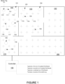
- Figure 1 shows a structure that includes a first set of sensors 121, 122, 123, 124, 125, a second set of sensors 131, 132, 133, 134, 135, and a controller 190 that estimates a location of a mobile tag 101 based on sensed signals of the first set of sensors 121, 122, 123, 124, 125, and the second set of sensors 131, 132, 133, 134, 135, according to an embodiment.
- the first set of sensors 121, 122, 123, 124, 125 sense a first condition of the structure.
- the second set of sensors 131, 132, 133, 134, 135 sense a second condition of the structure.
- the structure is represented by grid points.
- the grid points provide an overlay that section up the structure, wherein each grid point represents a different location within the structure.
- the grid points are evenly-spaced throughout the structure.
- Exemplary grid points are shown in Figure 1 as grid points 110, 111, 112, 113, 114, 115, 116, 117, 118, 119. Note that in Figure 1 many of the grid points do not have reference designators.
- the structure includes several rooms 140, 150, 160, 170, 180 which all include grid points.
- a controller 190 is connected to each of the first set of sensors 121, 122, 123, 124, 125, and the second set of sensors 131, 132, 133, 134, 135.
- the connection between the controller 190 and each sensor can include wired or wireless connections.
- each sensor includes a wireless router, and the connection between the controller and each of the sensors can include one or more wireless hops through one or more other sensors.
- the controller 190 operates to generate a first set of weighted likelihoods based on the first sensed condition of the structure, wherein the first set of weighted likelihoods includes a weighted likelihood of the mobile tag 101 being at each one of a plurality of grid points within the structure. That is, based on the sensing by the first set of sensors, the controller generates a weighted likelihood that the mobile tag 101 is at each of the grid points.
- the first set of sensor includes motion sensors that each sense motion within the structure. Based on the sensed motion, of each of the first set of sensors, the controller generates a map of the grid points that includes a weighted likelihood that the mobile tag 101 is located at each of the grid points.
- the controller 190 operates to generate a second set of weighted likelihoods based on the second sensed condition of the structure, wherein the second set of weighted likelihoods includes a weighted likelihood of the mobile tag 101 being at each one of the plurality of grid points within the structure. That is, based on the sensing by the second set of sensors, the controller generates a weighted likelihood that the mobile tag is at each of the grid points.
- the second set of sensor includes RF (radio frequency) sensors that each sense wireless signals within the structure. Based on the RF signals of each of the first set of sensors, the controller generates a map of the grid points that includes a weighted likelihood that the mobile tag 101 is located at each of the grid points.
- At least one of the first set of sensor, the second set of sensor, or a third set of sensor includes acoustic sensors.
- sound vibrations generated by the mobile tag are sensed by the acoustic sensors.
- a time of flight can be estimated by knowing when the sound vibrations are generated and by knowing when the sound vibrations are sensed by the acoustic sensors.
- the distance between the mobile tag and the acoustic sensors can be estimated.
- a set of weighted likelihoods of the mobile tag 101 being at each one of the plurality of grid points within the structure can be generated by the distance estimates determined through the use of the acoustic sensors.
- the controller 190 after generating the first set of weighted likelihoods and the second set of weighted likelihoods, the controller 190 operates to generate a combined set of likelihoods based on the first set of weighted likelihoods and the second set of weighted likelihoods. It is to be understood that the combined set of likelihoods can include any number of possible sets of weighted likelihoods.
- the controller operates to estimate a location of the mobile tag 101 within the structure based on the combined set of likelihoods. That is, the combined set of likelihoods includes a weighted likelihood that the mobile tag is located at each of the grid points.
- the combined set of likelihoods is based on at least the weighted likelihoods of the first set of sensors and the weighted likelihoods second set of sensors.
- the location of the mobile tag 101 can be estimated based on the locations of the grid points corresponding with the greatest weighted likelihoods of the combined set of likelihoods.
- Figure 2 shows maps 210, 220 of weighted likelihoods for the first set of sensors and for the second set of sensors, and a combined weighted likelihood map 230 based on the maps 210, 220 of the weighted likelihoods for the first set of sensors and for the second set of sensors.
- the maps 210, 220, 230 of Figure 2 show weighted likelihoods of the mobile tag being at grid points 110, 111, 112, 116, 117, 118 and other non-referenced grid points within the room 114 of the structure.
- the exemplary map 210 shows a weighted likelihood that the mobile tag is at each of the grid points based on the sensed first condition of the structure as sensed by the plurality of first sensors. This map represents a greater likelihood with more cross-hatch lines. That is, the weighted likelihood at the grid point 110 (no cross-hatching) is less than the weighted likelihood at the grid point 118 (more cross-hatching).
- the exemplary map 220 shows a weighted likelihood that the mobile tag is at each of the grid points based on the sensed second condition of the structure as sensed by the plurality of second sensors. Again, this map represents a greater likelihood with more cross-hatch lines. That is, the weighted likelihood at the grid point 110 (no cross-hatching) is less than the weighted likelihood at the grid point 118 (more cross-hatching).
- the exemplary map 230 shows the combined weighted likelihoods of the weighted likelihoods of the first sensed condition and the weighted likelihoods of the second sensed condition.
- additional weighted likelihood maps can be created and included in the determination of the combined weighted likelihoods map 230.
- the location of the mobile tag can be estimated based on the grid points of the combined weighted likelihoods map 230 that indicate the greatest likelihood.
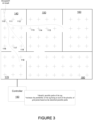
- Figure 3 shows a structure, wherein the structure is characterized by the grid points and another weighted likelihood map can be created by identifying possible paths of the mobile tag 101, according to an embodiment.
- the exemplary structure includes the rooms 140, 150, 160, 170, 180. Further, as shown, the structure includes the grid points (such as, grid points 110, 111, 112, 113, 114, 115, 116, 117, 118, 119) at various locations within the structure.
- an occupant or user of the mobile tag (for example, as depicted at time t0) is located at a location (such as defined by grid point 110).
- the occupant possesses (or is attached to) the previously described mobile tag 101.
- the term occupant and mobile tag may be used interchangeably.
- the likelihood that the occupant is located at another grid point in the future is estimated. Many factors can be utilized in the estimation.
- the controller 190 associated with the structure performs the estimating. While shown as a single controller 190, it is to be understood that the processing of the depicted controller 190 can be performed by a distributed set of processors. Further, the process may be performed remotely.
- the controller 190 is operative to determine an initial location of a tag at an initial time, determine a floor plan of a structure, and estimate a probability (likelihood) that at a future point in time that the tag is located at each of a plurality of grid points, wherein each of the plurality of grid points is associated with a different location within the structure.
- estimating the probability (likelihood) that at the future point in time that the tag is located at each of the plurality of grid points includes identifying possible paths of the tag, estimating the probability of the tag being at each of the plurality of grid points based on the identified possible paths, a difference between the future point in time and the initial time, and a distance between the initial position and positions of each of the plurality of grid points.
- the controller 190 further operates to generate the combined set of likelihoods based on the first set of weighted likelihoods, the second set of weighted likelihoods, and the third set of weighted likelihoods. That is, for example, a third weighted likelihood map is generated, and this third map is additionally used in the determination of the combined set of likelihoods.
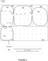
- Figure 4 shows a structure, wherein the structure is characterized by convex shapes that include the grid points, according to an embodiment.
- the barriers or walls of the structure define areas in which possible paths of the occupant cannot cross.
- the physical barriers or walls of the structure define convex shapes 240, 250, 260, 270, wherein each of the convex shapes includes groups of grid points. That is, for at least some embodiments, the total number of grid points within the structure and grouped into sub-groups forming a plurality of convex shapes (such as, convex shapes 240, 250, 260, 270).
- estimating the probability of the tag being at each of the plurality of grid points includes estimating a probability the tag is within the convex shape associated with the grid point.
- a shape of each of the plurality of convex shapes is defined by barriers of the structure, and connecting points 225, 235, 245 between each of the plurality of convex shapes 240, 250, 260, 270 are defined by openings between the barriers of the structure.
- each of the possible paths pass through the connecting points between the convex shapes.
- the connecting points are used for identifying paths through the structure.
- Utilizing convex shapes that include multiple grid points can substantially improve the processing needed to determine the probability that the tag is at each of the plurality of grid points. That is, calculating the probability that the tag is at each of the plurality of grid points using information from all of the grid points takes substantially more computational power than calculating the probability that the tag is at each of the plurality of grid points using information from convex shapes, thereby improving the processing of controller that is operative to calculate the probability that the tag is at each of the plurality of grid points.
- At least some embodiments include providing navigation between points (locations) of the structure.
- knowledge of grid points, convex shapes of the grid points, and/or connecting points between the convex shapes are used in determining navigation between locations of the structure.
- the connecting paths are utilized for determining a shortest path between location points within the structure.
- a user or a mobile computing device (mobile tag) of the user can submit a request to the controller for a shortest path between a present location of the user or the mobile device of the user, and a specified or desired location of the user.
- the controller uses the connecting points of the convex shapes of the grid points to identify the shortest path between the present location of the user and the desired or specified location of the user. Using the connecting points for the determination of the shortest path rather than all of the grid points substantially reduces the processing of the controller.
- the controller provides a user with a shortest path between points for navigation between two points.
- the utilization of the connecting points between the convex shapes provides the ability to determine point to point navigation using less processing than is all the grid points were to be utilized.
- Figure 5 shows time lines that depict the estimated weighted likelihood of a tag being located at specific grid points over time, according to an embodiment.
- estimating the weighted likelihood that at the future point in time that the tag is located at each of the plurality of grid points 113, 117, 118 include generating the first set of weighted likelihoods based on the first sensed condition of the structure, wherein the first set of weighted likelihoods includes a weighted likelihood of the mobile tag being at each one of a plurality of grid points within the structure, generating a second set of weighted likelihoods based on the second sensed condition of the structure, wherein the second set of weighted likelihoods includes a weighted likelihood of the mobile tag being at each one of the plurality of grid points within the structure, generating a combined set of likelihoods based on the first set of weighted likelihoods and the second set of weighted likelihoods.
- estimating the weighted likelihood that at the future point in time that the tag is located at each of the plurality of grid points 113, 117, 118 further includes identifying possible paths of the tag, estimating the probability of the tag being at each of the plurality of grid points 113, 117, 118 based on the identified possible paths, a difference between the future point in time and the initial time, and a distance between the initial position and positions of each of the plurality of grid points 113, 117, 118.
- Figure 6 shows a structure, wherein the structure includes a tag 550 that communicates with a sensor 410 and/or 412 of the structure, according to an embodiment.
- the communication between the tag and the sensor can be facilitated by any form of communication.
- the communication includes electromagnetic waves, such as, radio frequency (RF) or optical waves.
- RF radio frequency
- the sensed parameter is associated with the tag 550.
- the sensed parameter includes an estimate of a quality of a wireless link between the tag 550 and the one or more sensors 410, 412.
- the one or more sensors include a transceiver, and the link quality includes a received signal strength indicator (RSSI) between the transceiver and the mobile tag 550.
- RSSI received signal strength indicator
- the RSSI is determined by signals received by the one or more sensors from the mobile tag 550.
- the RSSI is determined by signals received by the mobile tag 550 from the one or more sensors.
- a distance between the mobile tag 550 and each of the sensors is approximated base on a different in signal power of transmitted signals relative to the RSSI.
- the distance estimate between the mobile tag and each of the sensors is used to estimate the location of the mobile tag.
- locations of each of the sensors is known, and the location of the mobile tag is estimated by triangulating using the known locations of the sensors and the estimated distance between each of the sensors and the mobile tag.
- At least one of the sensed parameter includes sensed motion of the tag.
- sensing motion includes sensing whether are not the tag is moving.
- sensing motion includes sensing a changing location of the tag, or detecting Significant Motion Detection of an Android virtual sensor.
- the mobile tag includes a pedometer.
- the sensors include a motion sensor.
- the motion sensor includes a passive infrared (PIR) sensor.
- the sensed parameter includes sensed ambient light.
- the sensed parameter includes sensed acceleration of the tag.
- the acceleration is sensed by the tag itself.
- the tag can include an accelerometer that senses acceleration of the tag, which is then communicated to one of the sensors (such as, sensor 410, 412).
- the acceleration is sensed by an external device. That is, the acceleration of the mobile tag can be sensed externally from the tag by another sensor.
- the acceleration is used to estimate orientation of the mobile tag with respect to gravity.
- Orientation of the mobile can be used to estimate expected RF strength due to antenna patterns and this expectation can be used to better calculate distance from a sensor and a probability of the distance of the tag from the sensor.
- a compass and/or a gyroscope are used for orientation with respect to the earth, giving better orientation knowledge between one or more of the sensors and the mobile tag.
- orientation of the mobile tag provides information that can be used to determine how the peaks and nulls of the antenna patterns of the mobile tag alignment with one or more of the sensors. Accordingly, determinations of link qualities between the device and sensors can be more precisely determined and compensation for varying orientations of the tag and the varying antenna patterns that result due to the varying orientation of the tag. For an embodiment, the compensation improves estimates of the distance between the mobile tag and each the sensors, which can improve the location estimation of the mobile tag.
- the sensed parameter includes sensed motion of the tag, wherein the motion is sensed by the tag, and communicated to the one or more sensors.
- the sensed parameter includes pedometer information from the tag. The motion sensed by the mobile tag and/or the pedometer information can be used to estimate distances traveled by the user of the mobile tag, and/or directions traveled by the user of the mobile tag.
- the sensed parameter includes directional (such as, magnetic) information from the tag.
- the sensed parameter includes tag orientation. Tag orientation may be delivered as a quaternion, euler angles, or rotational matrix.
- the sensed parameter includes sensed magnetic information from the tag.
- the sensed magnetic information of the tag is utilized to generate magnetic mapping of the structure.
- the sensed magnetic information is used to build a data base of a blue print of the structure.
- FIG. 7 shows a sensor of the structure, according to an embodiment.
- An embodiment of a smart sensor system 602 (which operate as the previously described sensors) includes a smart sensor CPU 635, a set of sensors 640, and a communication interface 650.
- a non-exhaustive list of sensors of the set of sensors 640 includes a light sensor 641, a motion sensor 642, a temperature sensor 643, a camera 644, and/or an air quality sensor 645.
- the smart sensor system 602 along with an environmental control manager 604 provide and environmental control sub-system 600.
- one or more of the set of sensors 640 is used for sensing conditions within the structure for generating the first set of weighted likelihoods based on the first sensed condition of the structure, wherein the first set of weighted likelihoods includes a weighted likelihood of the mobile tag being at each one of a plurality of grid points within the structure, and generating a second set of weighted likelihoods based on the second sensed condition of the structure, wherein the second set of weighted likelihoods includes a weighted likelihood of the mobile tag being at each one of the plurality of grid points within the structure.
- the weighted likelihoods are used for estimating a location of the mobile tag.
- the estimated locations of the mobile tag are used for controlling an environmental condition of the structure. That is, knowing the locations (or estimates of the locations) of mobile tags and the users associated with the mobile tags allows for intelligent control of the environment of the structure. For example, areas of the structure that do not include any occupants (users) can have lights dimmed or turned off. Further, rooms with no occupants or a large number of occupants can be temperature (through, for example, an HVAC (heating, ventilation, and air conditioning) system of the structure) controlled accordingly.
- HVAC heating, ventilation, and air conditioning
- one or more of the set of sensors 640 are used for the sensing conditions which are additionally used to control the environment (for example, lighting control and or HVAC (heating, ventilation, and air conditioning) of the structure. That is, for an embodiment, the environment of the structure is controlled by both the predicted location of the mobile tag (which typically include many mobile tags) and sensed conditions of the smart sensor system 602. For example, if a large number of mobile tags are identified to be location within a common room of the structure, the temperature of the room can be adjusted lower for comfort or energy savings. Additionally, or alternatively, the lighting of the room can be adjusted up or down.
- the environment of the structure is controlled by both the predicted location of the mobile tag (which typically include many mobile tags) and sensed conditions of the smart sensor system 602. For example, if a large number of mobile tags are identified to be location within a common room of the structure, the temperature of the room can be adjusted lower for comfort or energy savings. Additionally, or alternatively, the lighting of the room can be adjusted up or down.
- the communication interface 650 of the smart sensor system provides a communication channel for communicating with other smart sensors, with mobile tags, or with a backend server (such as, controller 190).
- the communication can include RF (radio frequency) communication, such as, WiFi or Bluetooth wireless communication.
- the smart sensor CPU 635 provides intelligent control of the smart sensor system 602 by managing the communication and for some embodiments providing at least a portion of the location determination of the mobile tag(s).
- the environmental control manager 604 which includes a managing CPU 620 receives control information from the smart sensor system 603 and provides control of an environmental control unit 646.
- the environmental control unit 646 includes an HVAC (heating, ventilation, and air conditioning) system.
- the environmental control unit 646 includes lighting control.
- the environmental control unit 646 includes HVAC (heating, ventilation, and air conditioning) and lighting control.
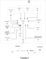
- Figure 8 shows a mobile tag 700 associated with an occupant of the structure, according to an embodiment. As previously described, for at least some embodiments, the mobile tag 700 provides sensed information that can be additionally used to estimate a location of the mobile tag 700 within the structure.
- the sensed information of the mobile tag 700 is used to generate another set of weighted likelihoods, wherein the set of weighted likelihoods includes a weighted likelihood of the mobile tag 700 being at each one of a plurality of grid points within the structure.
- the sensed information of the mobile tag 700 is communicated to the controller 190, to aid in location determination of the mobile tag 700.
- the mobile tag 700 communicates with a sensor 410 which is connected to an upstream network that includes the controller 190.
- the mobile tag 700 includes a controller 710 that manages the sensed information and manages communication of the tag through, for example, a radio 775.
- a non-exhaustive list of sensors of the mobile tag includes a GPS (global positioning system) receiver 720, a pedometer 730, a camera 735, a motion detector 740, a microphone 750, a compass 770, a gyroscope 772, a barometric sensor 784, a thermometer 774, and/or a light sensor 776.
- GPS global positioning system
- the mobile tag 700 includes a user profile 760 which can include customized information associated with the user of the mobile tag 700.
- the customized information can include tendencies and preferences of the user which can be used to further aid the location estimation of the mobile tag, and/or can be used to communicate preferential environmental control information which can be used along with the location estimation of the tag to control the environment of the structure in which the mobile tag is located.
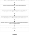
- FIG. 9 is a flow chart that includes steps of a method of estimating weighted likelihood of a mobile tag being at grid points of a structure, according to an embodiment.
- a first step 910 includes sensing, by a plurality of first sensors, a first condition of the structure.
- a second step 920 includes sensing, by a plurality of second sensors, a second condition of the structure.
- a third step 930 includes generating a first set of weighted likelihoods based on the first sensed condition of the structure, wherein the first set of weighted likelihoods includes a weighted likelihood of a mobile tag being at each one of a plurality of grid points within the structure.
- a fourth step 940 includes generating a second set of weighted likelihoods based on the second sensed condition of the structure, wherein the second set of weighted likelihoods includes a weighted likelihood of the mobile tag being at each one of the plurality of grid points within the structure.
- a fifth step 950 includes generating a combined set of likelihoods based on the first set of weighted likelihoods and the second set of weighted likelihoods.
- a sixth step 960 includes estimating a location of the mobile tag within the structure based on the combined set of likelihoods.
- the first plurality of sensors includes motion sensors
- the second plurality of sensors comprises RF sensors
- the combined set of likelihoods comprises an ensemble of the first set of weighted likelihoods and the second set of weighted likelihoods.
- the first plurality of sensors comprises passive infrared (PIR) sensors and the sensed first condition of the structure comprises sensed motion of the structure.
- the second plurality of sensors comprises wireless transceivers and the sensed second condition of the structure comprises a received signal strength of wireless signals between the mobile tag and the second plurality of sensors.
- the amount of motion sensed by the motion sensors influences the weighted likelihood. That is, a motion sensor that senses larger amounts of motion is more likely to be proximate to the mobile tag. Further, for an embodiment, sensed motion of different motion sensors is used to disambiguate between different mobile tags. For an embodiment, a size of an asset associated with the tag influences the weighted likelihoods. That is, a larger asset may generate a larger sensed motion signal. The larger sensed motion due to the size of the asset can be accounted for.
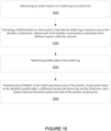
- Figure 10 is a flow chart that includes steps of a method of estimating weighted likelihood of a mobile tag being at grid points of a structure, according to an embodiment.
- a first step 1010 includes determining an initial location of the mobile tag at an initial time.
- a second step 1020 includes estimating a likelihood that at a future point in time that the mobile tag is located at each of the plurality of grid points, wherein each of the plurality of grid points is associated with a different location within the structure.
- estimating the likelihood that at the future point in time that the mobile tag is located at each of the plurality of grid points includes a third step 1022 of identifying possible paths of the mobile tag, and a fourth step 1024 of generating a third set of weighted likelihoods of the mobile tag being at each of the plurality of grid points based on the identified possible paths, a difference between the future point in time and the initial time, and a distance between the initial position and positions of each of the plurality of grid points.
- the grid points are equally spaced are substantially equally spaced throughout at least a portion of the structure.
- At least some embodiments include generating the combined set of likelihoods based on the first set of weighted likelihoods, the second set of weighted likelihoods, and the third set of weighted likelihoods.
- determining the initial location of the mobile tag at the initial time includes identifying when the user of the mobile tag enters the structure.
- the initial location is the entry point of the user.
- determining the initial location of the mobile tag at the initial time includes selecting a location based on the RSSI, without considering building walls constraints. Room level location consistency is used to select the initial location. That is, the number of times the RSSI indicates the tag is within a specific room of the structure can be used as an initial location determination.
- determining the initial location of the mobile tag at the initial time includes the user of the mobile device proactively sending a message that indicates an initial location of the user of the mobile tag.
- the initial location and the timing can be communicated, for example, to the controller 190.
- the controller further operates to group the plurality of grid points into sub-pluralities forming a plurality of convex shapes, wherein each of the sub-pluralities of grid points define a convex shape within the structure, and wherein estimating the likelihood of the tag being at each of the plurality of grid points comprises estimating a likelihood the tag is within the convex shape associated with the grid point.
- a shape of each of the plurality of convex shapes is defined by barriers of the structure, and connecting points between each of the plurality of convex shapes are defined by openings between the barriers of the structure.
- each of the possible paths pass through the connecting points between convex shapes.
- the controller further operates to generate a fourth set of weighted likelihoods based on a physical shape of the structure or characteristics of the structure, and generate the combined set of likelihoods based on the first set of weighted likelihoods, the second set of weighted likelihoods, and the fourth set of weighted likelihoods.
- the physical shape of the structure includes the physical shape and characteristics (such as, unique wall structure and/or materials) of the structure.
- the physical shape of the structure includes the fourth weighted likelihood of each grid points being influenced by a proximity of grid point to walls.
- the physical shape of the structure includes the fourth weighted likelihood of each grid points being influenced by detection of multipath signals within the structure.
- the physical shape of the structure includes the fourth weighted likelihood of each grid points being influenced by determination of RF signal attenuation within the structure.
- the controller further operates to receive a parameter sensed by the mobile tag.
- the parameter includes sensed acceleration of the mobile tag.
- the parameter comprises pedometer information from the tag.
- the parameter comprises directional (for example, magnetic) information from the tag.
- the parameter includes sensed magnetic information from the tag.
- the sensed magnetic information of the tag is utilized to generate magnetic mapping of the structure.
- the magnetic information is used to build a data base of a blue print of the structure.
- RSSI has been described as a method for determining distances between the mobile tag and the sensors
- ambient light sensor and other combinations of sensors other than RSSI/beacons are used for determining the distances.
- a bi-direction BLE (Bluetooth enabled) radio of the magnetic tag is operative to both send and receive beacons from the sensor.
- the mobile tag transmits tag beacons which are received by the sensors.
- transmit power of the tag beacons is varied over time. Using lower transmit power reduces the number of sensors that will receive the message, which can provide greater location accuracy.
- a floor plan of the structure is either previously known, or is provided.
- the floor plan in deduced, for example, by the controller 190 over time by sensing or tracking motion of tags/occupants over time.
- Walls for example, can be identified because mobile tags never travel through walls.
- motion sensors such as, PIR (passive infrared) sensors are used to time synchronized the sensors which can be used to aid the previously described triangulation.
- PIR passive infrared
Landscapes
- Engineering & Computer Science (AREA)
- Computer Networks & Wireless Communication (AREA)
- Signal Processing (AREA)
- Physics & Mathematics (AREA)
- General Physics & Mathematics (AREA)
- Radar, Positioning & Navigation (AREA)
- Remote Sensing (AREA)
- Electromagnetism (AREA)
- Probability & Statistics with Applications (AREA)
- Position Fixing By Use Of Radio Waves (AREA)
- Mobile Radio Communication Systems (AREA)
- Radar Systems Or Details Thereof (AREA)
Description
- The described embodiments relate generally to building controls. More particularly, the described embodiments relate to location estimation of a mobile tag within a structure.
- Intelligent building control provides for control of structure that is user intelligent. That is, based on behavior or predicted behavior of users within the structure, the intelligent building control provides the users with intelligent environmental controls, safety controls, logistical, and/or information control.
- It is desirable to have a method, system and apparatus for predicting locations of an occupant or an asset, or a tag associated with the occupant or asset, within a structure.
-
US 2016/286624 A1 (GORDON G; MOHAN T; PATEL S), 29 September 2016 (2016-09-29), relates to association information with an asset or a physical space. -
US 2017/017214 A1 (O'KEEFFE JAMES THOMAS [US]), 19 Januar 2017 (2017-01-19), relates to a system and method for estimating the number of people in a smart building. - One embodiment of the invention includes a building control system according to claim 1. The building control system incldudes a tag, wherein the mobile tag operates to move within a structure and a plurality of first sensors, wherein the plurality of first sensors operates to sense a first condition of the structure. The building control system further includes a plurality of second sensors, wherein the plurality of second sensors operates to sense a second condition of the structure, and a controller. The controller operates to generate a first set of weighted likelihoods based on the first sensed condition of the structure, wherein the first set of weighted likelihoods includes a weighted likelihood of the mobile tag being at each one of a plurality of grid points within the structure, wherein the grid points provide an overlay that section up the structure and each grid point represents a different location within the structure, generate a second set of weighted likelihoods based on the second sensed condition of the structure, wherein the second set of weighted likelihoods includes a weighted likelihood of the mobile tag being at each one of the plurality of grid points within the structure, generate a combined set of likelihoods based on the first set of weighted likelihoods and the second set of weighted likelihoods, wherein the combined set of weighted likelihoods includes a weighted likelihood of the mobile tag being at each one of the plurality of grid points within the structure, and estimate a location of the mobile tag within the structure based on the combined set of likelihoods.
- Another embodiment of the invention includes a method according to claim 12. The method includes sensing, by a plurality of first sensors, a first condition of the structure, sensing, by a plurality of second sensors, a second condition of the structure, generating a first set of weighted likelihoods based on the first sensed condition of the structure, wherein the first set of weighted likelihoods includes a weighted likelihood of a mobile tag being at each one of a plurality of grid points within the structure, wherein the grid points provide an overlay that section up the structure and each grid point represents a different location within the structure, generating a second set of weighted likelihoods based on the second sensed condition of the structure, wherein the second set of weighted likelihoods includes a weighted likelihood of the mobile tag being at each one of the plurality of grid points within the structure, generating a combined set of likelihoods based on the first set of weighted likelihoods and the second set of weighted likelihoods, wherein the combined set of weighted likelihoods includes a weighted likelihood of the mobile tag being at each one of the plurality of grid points within the structure, and estimating a location of the mobile tag within the structure based on the combined set of likelihoods.
- Other aspects and advantages of the described embodiments will become apparent from the following detailed description, taken in conjunction with the accompanying drawings, illustrating by way of example the principles of the described embodiments.
-
-
Figure 1 shows a structure that includes a first set of sensors, a second set of sensors, and a controller that estimates a location of a mobile tag based on sensed signals of the first and second sets of sensors, according to an embodiment. -
Figure 2 shows maps of weighted likelihoods for the first set of sensors and for the second set of sensors, and a combined weighted likelihood map based on the maps of the weighted likelihoods for the first set of sensors and for the second set of sensors. -
Figure 3 shows a structure, wherein the structure is characterized by grid points and another weighted likelihood map can be created by identifying possible paths of the mobile tag, according to an embodiment. -
Figure 4 shows a structure, wherein the structure is characterized by convex shapes that include grid points, according to an embodiment. -
Figure 5 shows time lines that depict estimated probabilities of a tag being located at specific grid points over time, according to an embodiment. -
Figure 6 shows a structure, wherein the structure includes a tag that communicates with a sensor of the structure, according to an embodiment. -
Figure 7 shows a sensor of the structure, according to an embodiment. -
Figure 8 shows a tag associated with an occupant of the structure, according to an embodiment. -
Figure 9 is a flow chart that includes steps of a method of estimating weighted likelihood of a mobile tag being at grid points of a structure, according to an embodiment. -
Figure 10 is a flow chart that includes steps of a method of estimating weighted likelihood of a mobile tag being at grid points of a structure, according to an embodiment. - The described embodiments are embodied in methods, apparatuses, and systems for generating weighted likelihood maps for estimating a location of a mobile tag. A first weighted likelihood map is generated based on sensed signals of a first type of sensor. A second weighted likelihood map is generated based on sensed signals of a second type of sensor. A combined set of likelihoods is generated based on the first set of weighted likelihoods and the second set of weighted likelihoods. A location of the mobile tag within the structure is estimated based on the combined set of likelihoods. Additional weighted likelihood maps can be generated to improve the estimation of the location of the mobile tag. For an embodiment, grid points within a structure are identified, and weighted likelihoods of the tag being located at different grid points are estimated. For at least some embodiments, the weighted likelihoods are supplemented with information associated with the tag. At least some embodiments include supplementing building control and/or building intelligence with the estimated location of the mobile tag.
-
Figure 1 shows a structure that includes a first set ofsensors sensors controller 190 that estimates a location of amobile tag 101 based on sensed signals of the first set ofsensors sensors sensors sensors - For an embodiment, the structure is represented by grid points. The grid points provide an overlay that section up the structure, wherein each grid point represents a different location within the structure. For an embodiment, the grid points are evenly-spaced throughout the structure. Exemplary grid points are shown in
Figure 1 asgrid points Figure 1 many of the grid points do not have reference designators. As shown inFigure 1 , the structure includesseveral rooms - For at least some embodiments, a
controller 190 is connected to each of the first set ofsensors sensors controller 190 and each sensor can include wired or wireless connections. For an embodiment, each sensor includes a wireless router, and the connection between the controller and each of the sensors can include one or more wireless hops through one or more other sensors. - For at least some embodiments, the
controller 190 operates to generate a first set of weighted likelihoods based on the first sensed condition of the structure, wherein the first set of weighted likelihoods includes a weighted likelihood of themobile tag 101 being at each one of a plurality of grid points within the structure. That is, based on the sensing by the first set of sensors, the controller generates a weighted likelihood that themobile tag 101 is at each of the grid points. For an embodiment, the first set of sensor includes motion sensors that each sense motion within the structure. Based on the sensed motion, of each of the first set of sensors, the controller generates a map of the grid points that includes a weighted likelihood that themobile tag 101 is located at each of the grid points. - Further, for at least some embodiments, the
controller 190 operates to generate a second set of weighted likelihoods based on the second sensed condition of the structure, wherein the second set of weighted likelihoods includes a weighted likelihood of themobile tag 101 being at each one of the plurality of grid points within the structure. That is, based on the sensing by the second set of sensors, the controller generates a weighted likelihood that the mobile tag is at each of the grid points. For an embodiment, the second set of sensor includes RF (radio frequency) sensors that each sense wireless signals within the structure. Based on the RF signals of each of the first set of sensors, the controller generates a map of the grid points that includes a weighted likelihood that themobile tag 101 is located at each of the grid points. - For at least some embodiments, at least one of the first set of sensor, the second set of sensor, or a third set of sensor includes acoustic sensors. For an embodiment, sound vibrations generated by the mobile tag are sensed by the acoustic sensors. A time of flight can be estimated by knowing when the sound vibrations are generated and by knowing when the sound vibrations are sensed by the acoustic sensors. Based on a time of flight, the distance between the mobile tag and the acoustic sensors can be estimated. A set of weighted likelihoods of the
mobile tag 101 being at each one of the plurality of grid points within the structure can be generated by the distance estimates determined through the use of the acoustic sensors. - For at least some embodiments, after generating the first set of weighted likelihoods and the second set of weighted likelihoods, the
controller 190 operates to generate a combined set of likelihoods based on the first set of weighted likelihoods and the second set of weighted likelihoods. It is to be understood that the combined set of likelihoods can include any number of possible sets of weighted likelihoods. - For at least some embodiments, the controller operates to estimate a location of the
mobile tag 101 within the structure based on the combined set of likelihoods. That is, the combined set of likelihoods includes a weighted likelihood that the mobile tag is located at each of the grid points. The combined set of likelihoods is based on at least the weighted likelihoods of the first set of sensors and the weighted likelihoods second set of sensors. The location of themobile tag 101 can be estimated based on the locations of the grid points corresponding with the greatest weighted likelihoods of the combined set of likelihoods. -
Figure 2 showsmaps weighted likelihood map 230 based on themaps
second set of sensors. Themaps Figure 2 show weighted likelihoods of the mobile tag being at grid points 110, 111, 112, 116, 117, 118 and other non-referenced grid points within theroom 114 of the structure. - The
exemplary map 210 shows a weighted likelihood that the mobile tag is at each of the grid points based on the sensed first condition of the structure as sensed by the plurality of first sensors. This map represents a greater likelihood with more cross-hatch lines. That is, the weighted likelihood at the grid point 110 (no cross-hatching) is less than the weighted likelihood at the grid point 118 (more cross-hatching). - The
exemplary map 220 shows a weighted likelihood that the mobile tag is at each of the grid points based on the sensed second condition of the structure as sensed by the plurality of second sensors. Again, this map represents a greater likelihood with more cross-hatch lines. That is, the weighted likelihood at the grid point 110 (no cross-hatching) is less than the weighted likelihood at the grid point 118 (more cross-hatching). - The
exemplary map 230 shows the combined weighted likelihoods of the weighted likelihoods of the first sensed condition and the weighted likelihoods of the second sensed condition. As previously described, additional weighted likelihood maps can be created and included in the determination of the combined weighted likelihoods map 230. - After the combined weighted likelihoods map 230 has been created, the location of the mobile tag can be estimated based on the grid points of the combined weighted likelihoods map 230 that indicate the greatest likelihood.
-
Figure 3 shows a structure, wherein the structure is characterized by the grid points and another weighted likelihood map can be created by identifying possible paths of themobile tag 101, according to an embodiment. As shown, the exemplary structure includes therooms
grid points (such as, grid points 110, 111, 112, 113, 114, 115, 116, 117, 118, 119) at various locations within the structure. For at least some embodiments, an occupant or user of the mobile tag (for example, as depicted at time t0) is located at a location (such as defined by grid point 110). For at least some embodiments, the occupant possesses (or is attached to) the previously describedmobile tag 101. For descriptive purposes, the term occupant and mobile tag may be used interchangeably. For at least some embodiments, the likelihood that the occupant is located at another grid point in the future is estimated. Many factors can be utilized in the estimation. - For an embodiment, the
controller 190 associated with the structure performs the estimating. While shown as asingle controller 190, it is to be understood that the processing of the depictedcontroller 190 can be performed by a distributed set of processors. Further, the process may be performed remotely. - For an embodiment the
controller 190 is operative to determine an initial location of a tag at an initial time, determine a floor plan of a structure, and estimate a probability (likelihood) that at a future point in time that the tag is located at each of a plurality of grid points, wherein each of the plurality of grid points is associated with a different location within the structure. For at least some embodiments, estimating the probability (likelihood) that at the future point in time that the tag is located at each of the plurality of grid points, includes identifying possible paths of the tag, estimating the probability of the tag being at each of the plurality of grid points based on the identified possible paths, a difference between the future point in time and the initial time, and a distance between the initial position and positions of each of the plurality of grid points. - For at least some embodiments, the
controller 190 further operates to generate the combined set of likelihoods based on the first set of weighted likelihoods, the second set of weighted likelihoods, and the third set of weighted likelihoods. That is, for example, a third weighted likelihood map is generated, and this third map is additionally used in the determination of the combined set of likelihoods. -
Figure 4 shows a structure, wherein the structure is characterized by convex shapes that include the grid points, according to an embodiment. As shown, the barriers or walls of the structure define areas in which possible paths of the occupant cannot cross. For an embodiment, the physical barriers or walls of the structure defineconvex shapes convex shapes - Further, for at least some embodiments, estimating the probability of the tag being at each of the plurality of grid points includes estimating a probability the tag is within the convex shape associated with the grid point. As shown, for at least some embodiments, a shape of each of the plurality of convex shapes is defined by barriers of the structure, and connecting
points convex shapes - Utilizing convex shapes that include multiple grid points can substantially improve the processing needed to determine the probability that the tag is at each of the plurality of grid points. That is, calculating the probability that the tag is at each of the plurality of grid points using information from all of the grid points takes substantially more computational power than calculating the probability that the tag is at each of the plurality of grid points using information from convex shapes, thereby improving the processing of controller that is operative to calculate the probability that the tag is at each of the plurality of grid points.
- At least some embodiments include providing navigation between points (locations) of the structure. For at least some embodiments, knowledge of grid points, convex shapes of the grid points, and/or connecting points between the convex shapes are used in determining navigation between locations of the structure. For an embodiment, the connecting paths are utilized for determining a shortest path between location points within the structure. For example, a user or a mobile computing device (mobile tag) of the user can submit a request to the controller for a shortest path between a present location of the user or the mobile device of the user, and a specified or desired location of the user. For an embodiment, the controller uses the connecting points of the convex shapes of the grid points to identify the shortest path between the present location of the user and the desired or specified location of the user. Using the connecting points for the determination of the shortest path rather than all of the grid points substantially reduces the processing of the controller.
- That is, for an embodiment, the controller provides a user with a shortest path between points for navigation between two points. As described, the utilization of the connecting points between the convex shapes provides the ability to determine point to point navigation using less processing than is all the grid points were to be utilized.
-
Figure 5 shows time lines that depict the estimated weighted likelihood of a tag being located at specific grid points over time, according to an embodiment. For at least some embodiments, estimating the weighted likelihood that at the future point in time that the tag is located at each of the plurality of grid points 113, 117, 118, include generating the first set of weighted likelihoods based on the first sensed condition of the structure, wherein the first set of weighted likelihoods includes a weighted likelihood of the mobile tag being at each one of a plurality of grid points within the structure, generating a second set of weighted likelihoods based on the second sensed condition of the structure, wherein the second set of weighted likelihoods includes a weighted likelihood of the mobile tag being at each one of the plurality of grid points within the structure, generating a combined set of likelihoods based on the first set of weighted likelihoods and the second set of weighted likelihoods. For at least some embodiments, estimating the weighted likelihood that at the future point in time that the tag is located at each of the plurality of grid points 113, 117, 118, further includes identifying possible paths of the tag, estimating the probability of the tag being at each of the plurality of grid points 113, 117, 118 based on the identified possible paths, a difference between the future point in time and the initial time, and a distance between the initial position and positions of each of the plurality of grid points 113, 117, 118.
Figure 6 shows a structure, wherein the structure includes atag 550 that communicates with asensor 410 and/or 412 of the structure, according to an embodiment. The communication between the tag and the sensor can be facilitated by any form of communication. For an embodiment, the communication includes electromagnetic waves, such as, radio frequency (RF) or optical waves. - For at least some embodiments, the sensed parameter is associated with the
tag 550. For at least some embodiments, the sensed parameter includes an estimate of a quality of a wireless link between thetag 550 and the one ormore sensors mobile tag 550. For an embodiment, the RSSI is determined by signals received by the one or more sensors from themobile tag 550. For an embodiment, the RSSI is determined by signals received by themobile tag 550 from the one or more sensors. For an embodiment, a distance between themobile tag 550 and each of the sensors is approximated base on a different in signal power of transmitted signals relative to the RSSI. For an embodiment, the distance estimate between the mobile tag and each of the sensors is used to estimate the location of the mobile tag. For an embodiment, locations of each of the sensors is known, and the location of the mobile tag is estimated by triangulating using the known locations of the sensors and the estimated distance between each of the sensors and the mobile tag. - For at least some embodiments, at least one of the sensed parameter includes sensed motion of the tag. For an embodiment, sensing motion includes sensing whether are not the tag is moving. For an embodiment, sensing motion includes sensing a changing location of the tag, or detecting Significant Motion Detection of an Android virtual sensor. For an embodiment, the mobile tag includes a pedometer.
- For an embodiment, the sensors (such as
sensors 410, 412) include a motion sensor. For an embodiment, the motion sensor includes a passive infrared (PIR) sensor. For at least some embodiments, the sensed parameter includes sensed ambient light.
For at least some embodiments, the sensed parameter includes sensed acceleration of the tag. For an embodiment, the acceleration is sensed by the tag itself. For example, the tag can include an accelerometer that senses acceleration of the tag, which is then communicated to one of the sensors (such as,sensor 410, 412). For an embodiment, the acceleration is sensed by an external device. That is, the acceleration of the mobile tag can be sensed externally from the tag by another sensor. - For an embodiment, the acceleration is used to estimate orientation of the mobile tag with respect to gravity. Orientation of the mobile can be used to estimate expected RF strength due to antenna patterns and this expectation can be used to better calculate distance from a sensor and a probability of the distance of the tag from the sensor. For at least some embodiments, a compass and/or a gyroscope are used for orientation with respect to the earth, giving better orientation knowledge between one or more of the sensors and the mobile tag.
- For at least some embodiments, orientation of the mobile tag provides information that can be used to determine how the peaks and nulls of the antenna patterns of the mobile tag alignment with one or more of the sensors. Accordingly, determinations of link qualities between the device and sensors can be more precisely determined and compensation for varying orientations of the tag and the varying antenna patterns that result due to the varying orientation of the tag. For an embodiment, the compensation improves estimates of the distance between the mobile tag and each the sensors, which can improve the location estimation of the mobile tag.
- For at least some embodiments, the sensed parameter includes sensed motion of the tag, wherein the motion is sensed by the tag, and communicated to the one or more sensors. For at least some embodiments, the sensed parameter includes pedometer information from the tag. The motion sensed by the mobile tag and/or the pedometer information can be used to estimate distances traveled by the user of the mobile tag, and/or directions traveled by the user of the mobile tag. For at least some embodiments, the sensed parameter includes directional (such as, magnetic) information from the tag. For at least some embodiments, the sensed parameter includes tag orientation. Tag orientation may be delivered as a quaternion, euler angles, or rotational matrix.
For at least some embodiments, the sensed parameter includes sensed magnetic information from the tag. For at least some embodiments, the sensed magnetic information of the tag is utilized to generate magnetic mapping of the structure. For at least some embodiments, the sensed magnetic information is used to build a data base of a blue print of the structure. -
Figure 7 shows a sensor of the structure, according to an embodiment. An embodiment of a smart sensor system 602 (which operate as the previously described sensors) includes asmart sensor CPU 635, a set ofsensors 640, and acommunication interface 650. For an embodiment, a non-exhaustive list of sensors of the set ofsensors 640 includes alight sensor 641, amotion sensor 642, atemperature sensor 643, acamera 644, and/or anair quality sensor 645. For an embodiment, thesmart sensor system 602 along with anenvironmental control manager 604 provide andenvironmental control sub-system 600. - For at least some embodiments, one or more of the set of
sensors 640 is used for sensing conditions within the structure for generating the first set of weighted likelihoods based on the first sensed condition of the structure, wherein the first set of weighted likelihoods includes a weighted likelihood of the mobile tag being at each one of a plurality of grid points within the structure, and generating a second set of weighted likelihoods based on the second sensed condition of the structure, wherein the second set of weighted likelihoods includes a weighted likelihood of the mobile tag being at each one of the plurality of grid points within the structure. As described, for at least some embodiments, the weighted likelihoods are used for estimating a location of the mobile tag. - For at least some embodiments, the estimated locations of the mobile tag are used for controlling an environmental condition of the structure. That is, knowing the locations (or estimates of the locations) of mobile tags and the users associated with the mobile tags allows for intelligent control of the environment of the structure. For example, areas of the structure that do not include any occupants (users) can have lights dimmed or turned off. Further, rooms with no occupants or a large number of occupants can be temperature (through, for example, an HVAC (heating, ventilation, and air conditioning) system of the structure) controlled accordingly.
- For at least some embodiments, one or more of the set of
sensors 640 are used for the sensing conditions which are additionally used to control the environment (for example, lighting control and or HVAC (heating, ventilation, and air conditioning) of the structure. That is, for an embodiment, the environment of the structure is controlled by both the predicted location of the mobile tag (which typically include many mobile tags) and sensed conditions of thesmart sensor system 602. For example, if a large number of mobile tags are identified to be location within a common room of the structure, the temperature of the room can be adjusted lower for comfort or energy savings. Additionally, or alternatively, the lighting of the room can be adjusted up or down. - The
communication interface 650 of the smart sensor system provides a communication channel for communicating with other smart sensors, with mobile tags, or with a backend server (such as, controller 190). The communication can include RF (radio frequency) communication, such as, WiFi or Bluetooth wireless communication. - The
smart sensor CPU 635 provides intelligent control of thesmart sensor system 602 by managing the communication and for some embodiments providing at least a portion of the location determination of the mobile tag(s). - The
environmental control manager 604 which includes a managingCPU 620 receives control information from the smart sensor system 603 and provides control of anenvironmental control unit 646. For an embodiment, theenvironmental control unit 646 includes an HVAC (heating, ventilation, and air conditioning) system. For an embodiment, theenvironmental control unit 646 includes lighting control. For an embodiment, theenvironmental control unit 646 includes HVAC (heating, ventilation, and air conditioning) and lighting control.
Figure 8 shows amobile tag 700 associated with an occupant of the structure, according to an embodiment. As previously described, for at least some embodiments, themobile tag 700 provides sensed information that can be additionally used to estimate a location of themobile tag 700 within the structure. For an embodiment, the sensed information of themobile tag 700 is used to generate another set of weighted likelihoods, wherein the set of weighted likelihoods includes a weighted likelihood of themobile tag 700 being at each one of a plurality of grid points within the structure. - For an embodiment, the sensed information of the
mobile tag 700 is communicated to thecontroller 190, to aid in location determination of themobile tag 700. For an embodiment, themobile tag 700 communicates with asensor 410 which is connected to an upstream network that includes thecontroller 190. - As shown, for at least some embodiments, the
mobile tag 700 includes acontroller 710 that manages the sensed information and manages communication of the tag through, for example, aradio 775. - For at least some embodiments, a non-exhaustive list of sensors of the mobile tag includes a GPS (global positioning system)
receiver 720, apedometer 730, acamera 735, amotion detector 740, amicrophone 750, acompass 770, agyroscope 772, abarometric sensor 784, athermometer 774, and/or alight sensor 776. - Further, for at least some embodiments, the
mobile tag 700 includes auser profile 760 which can include customized information associated with the user of themobile tag 700. The customized information can include tendencies and preferences of the user which can be used to further aid the location estimation of the mobile tag, and/or can be used to communicate preferential environmental control information which can be used along with the location estimation of the tag to control the environment of the structure in which the mobile tag is located. - Further, the
mobile tag 700 can include a user input 782 (such as, a keyboard or touchscreen) to allow a user of the mobile tag to provide feedback information or user preferences. The feedback information of the user can be used to validate or invalidate the location estimations. For an embodiment, the user feedback influences future location estimations.
Figure 9 is a flow chart that includes steps of a method of estimating weighted likelihood of a mobile tag being at grid points of a structure, according to an embodiment. Afirst step 910 includes sensing, by a plurality of first sensors, a first condition of the structure. Asecond step 920 includes sensing, by a plurality of second sensors, a second condition of the structure. Athird step 930 includes generating a first set of weighted likelihoods based on the first sensed condition of the structure, wherein the first set of weighted likelihoods includes a weighted likelihood of a mobile tag being at each one of a plurality of grid points within the structure. Afourth step 940 includes generating a second set of weighted likelihoods based on the second sensed condition of the structure, wherein the second set of weighted likelihoods includes a weighted likelihood of the mobile tag being at each one of the plurality of grid points within the structure. Afifth step 950 includes generating a combined set of likelihoods based on the first set of weighted likelihoods and the second set of weighted likelihoods. Asixth step 960 includes estimating a location of the mobile tag within the structure based on the combined set of likelihoods. - As previously described, for at least some embodiments, the first plurality of sensors includes motion sensors, the second plurality of sensors comprises RF sensors, and wherein the combined set of likelihoods comprises an ensemble of the first set of weighted likelihoods and the second set of weighted likelihoods.
- As previously described, for at least some embodiments, the first plurality of sensors comprises passive infrared (PIR) sensors and the sensed first condition of the structure comprises sensed motion of the structure. As previously described, for at least some embodiments, the second plurality of sensors comprises wireless transceivers and the sensed second condition of the structure comprises a received signal strength of wireless signals between the mobile tag and the second plurality of sensors.
- For an embodiment, the amount of motion sensed by the motion sensors (such as, the PIR sensor) influences the weighted likelihood. That is, a motion sensor that senses larger amounts of motion is more likely to be proximate to the mobile tag. Further, for an embodiment, sensed motion of different motion sensors is used to disambiguate between different mobile tags. For an embodiment, a size of an asset associated with the tag influences the weighted likelihoods. That is, a larger asset may generate a larger sensed motion signal. The larger sensed motion due to the size of the asset can be accounted for.
-
Figure 10 is a flow chart that includes steps of a method of estimating weighted likelihood of a mobile tag being at grid points of a structure, according to an embodiment. Afirst step 1010 includes determining an initial location of the mobile tag at an initial time. Asecond step 1020 includes estimating a likelihood that at a future point in time that the mobile tag is located at each of the plurality of grid points, wherein each of the plurality of grid points is associated with a different location within the structure. For an embodiment, estimating the likelihood that at the future point in time that the mobile tag is located at each of the plurality of grid points includes athird step 1022 of identifying possible paths of the mobile tag, and afourth step 1024 of generating a third set of weighted likelihoods of the mobile tag being at each of the plurality of grid points based on the identified possible paths, a difference between the future point in time and the initial time, and a distance between the initial position and positions of each of the plurality of grid points. For at least some embodiments, the grid points are equally spaced are substantially equally spaced throughout at least a portion of the structure. - Further, at least some embodiments include generating the combined set of likelihoods based on the first set of weighted likelihoods, the second set of weighted likelihoods, and the third set of weighted likelihoods.
- For an embodiment, determining the initial location of the mobile tag at the initial time includes identifying when the user of the mobile tag enters the structure. The initial location is the entry point of the user.
- For an embodiment, determining the initial location of the mobile tag at the initial time includes selecting a location based on the RSSI, without considering building walls constraints. Room level location consistency is used to select the initial location. That is, the number of times the RSSI indicates the tag is within a specific room of the structure can be used as an initial location determination.
- For an embodiment, determining the initial location of the mobile tag at the initial time includes the user of the mobile device proactively sending a message that indicates an initial location of the user of the mobile tag. The initial location and the timing can be communicated, for example, to the
controller 190. - As previously described, for an embodiment, the controller further operates to group the plurality of grid points into sub-pluralities forming a plurality of convex shapes, wherein each of the sub-pluralities of grid points define a convex shape within the structure, and wherein estimating the likelihood of the tag being at each of the plurality of grid points comprises estimating a likelihood the tag is within the convex shape associated with the grid point. As previously described, for an embodiment, a shape of each of the plurality of convex shapes is defined by barriers of the structure, and connecting points between each of the plurality of convex shapes are defined by openings between the barriers of the structure. As previously described, for an embodiment, each of the possible paths pass through the connecting points between convex shapes.
- For at least some embodiments, the controller further operates to generate a fourth set of weighted likelihoods based on a physical shape of the structure or characteristics of the structure, and generate the combined set of likelihoods based on the first set of weighted likelihoods, the second set of weighted likelihoods, and the fourth set of weighted likelihoods. For at least some embodiments, the physical shape of the structure includes the physical shape and characteristics (such as, unique wall structure and/or materials) of the structure. For at least some embodiments, the physical shape of the structure includes the fourth weighted likelihood of each grid points being influenced by a proximity of grid point to walls. For at least some embodiments, the physical shape of the structure includes the fourth weighted likelihood of each grid points being influenced by detection of multipath signals within the structure. For at least some embodiments, the physical shape of the structure includes the fourth weighted likelihood of each grid points being influenced by determination of RF signal attenuation within the structure.
As previously described, for an embodiment, the controller further operates to receive a parameter sensed by the mobile tag. As previously described, for an embodiment, the parameter includes sensed acceleration of the mobile tag. - As previously described, for an embodiment, the parameter comprises pedometer information from the tag.
- As previously described, for an embodiment, the parameter comprises directional (for example, magnetic) information from the tag.
- As previously described, for an embodiment, the parameter includes sensed magnetic information from the tag.
- As previously described, for an embodiment, the sensed magnetic information of the tag is utilized to generate magnetic mapping of the structure. As previously described, for an embodiment, the magnetic information is used to build a data base of a blue print of the structure.
- While RSSI has been described as a method for determining distances between the mobile tag and the sensors, for at least some embodiments, ambient light sensor and other combinations of sensors other than RSSI/beacons are used for determining the distances. For an embodiment, a bi-direction BLE (Bluetooth enabled) radio of the magnetic tag is operative to both send and receive beacons from the sensor. For at least some embodiments, the mobile tag transmits tag beacons which are received by the sensors. For at least some embodiments, transmit power of the tag beacons is varied over time. Using lower transmit power reduces the number of sensors that will receive the message, which can provide greater location accuracy.
- For an embodiment, a floor plan of the structure is either previously known, or is provided. For an embodiment, the floor plan in deduced, for example, by the
controller 190 over time by sensing or tracking motion of tags/occupants over time. Walls, for example, can be identified because mobile tags never travel through walls. - For an embodiment, motion sensors, such as, PIR (passive infrared) sensors are used to time synchronized the sensors which can be used to aid the previously described triangulation.
- Although specific embodiments have been described and illustrated, the described embodiments are not to be limited to the specific forms or arrangements of parts so described and illustrated. The embodiments are limited only by the appended claims.
Claims (15)
- A building control system, comprising;a mobile tag (101, 700), wherein the mobile tag operates to move within a structure;a plurality of first sensors (121, 122, 123, 124, 125), wherein the plurality of first sensors operate to sense a first condition of the structure;a plurality of second sensors (131, 132, 133, 134, 135), wherein the plurality of second sensors operate to sense a second condition of the structure;a controller (190), characterised in that the controller operates to:generate a first set of weighted likelihoods based on the first sensed condition of the structure, wherein the first set of weighted likelihoods includes a weighted likelihood of the mobile tag (101, 700) being at each one of a plurality of grid points (110, 111, 112, 113, 114, 115, 116, 117, 118, 119) within the structure, wherein the grid points provide an overlay that section up the structure and each grid point represents a different location within the structure;generate a second set of weighted likelihoods based on the second sensed condition of the structure, wherein the second set of weighted likelihoods includes a weighted likelihood of the mobile tag (101, 700) being at each one of the plurality of grid points (110, 111, 112, 113, 114, 115, 116, 117, 118, 119) within the structure;generate a combined set of likelihoods based on the first set of weighted likelihoods and the second set of weighted likelihoods, wherein the combined set of weighted likelihoods includes a weighted likelihood of the mobile tag (101, 700) being at each one of the plurality of grid points (110, 111, 112, 113, 114, 115, 116, 117, 118, 119) within the structure; andestimate a location of the mobile tag (101, 700) within the structure based on the combined set of likelihoods.
- The system of claim 1, wherein the first plurality of sensors (121, 122, 123, 124, 125) comprises motion sensors, the second plurality of sensors (131, 132, 133, 134, 135) comprises RF sensors, and wherein the combined set of likelihoods comprises an ensemble of the first set of weighted likelihoods and the second set of weighted likelihoods.
- The system of claim 2, wherein the first plurality of sensors (121, 122, 123, 124, 125) comprises passive infrared (PIR) sensors and the sensed first condition of the structure comprises sensed motion of the structure.
- The system of claim 2, wherein the second plurality of sensors (131, 132, 133, 134, 135) comprises wireless transceivers and the sensed second condition of the structure comprises a received signal strength of wireless signals between the mobile tag (101, 700) and the second plurality of sensors (131, 132, 133, 134, 135).
- The system of claim 1, wherein the controller operates to:determine (1010) an initial location of the mobile tag (101, 700) at an initial time;estimate (1020) a likelihood that at a future point in time that the mobile tag (101, 700) is located at each of the plurality of grid points (110, 111, 112, 113, 114, 115, 116, 117, 118, 119), comprising the controller (190) operating to:identify (1022) possible paths of the tag (101, 700);generate (1024) a third set of weighted likelihoods of the tag (101, 700) being at each of the plurality of grid points (110, 111, 112, 113, 114, 115, 116, 117, 118, 119) based on the identified possible paths, a difference between the future point in time and the initial time, and a distance between the initial position and positions of each of the plurality of grid points (110, 111, 112, 113, 114, 115, 116, 117, 118, 119).
- The system of claim 5, wherein the controller (190) further operates to:
generate the combined set of likelihoods based on the first set of weighted likelihoods, the second set of weighted likelihoods, and the third set of weighted likelihoods. - The system of claim 5, wherein the controller (190) further operates to:group the plurality of grid points (110, 111, 112, 113, 114, 115, 116, 117, 118, 119) into sub-pluralities forming a plurality of convex shapes (240, 250, 260, 270), wherein each of the sub-pluralities of grid points define a convex shape within the structure, and wherein estimating the likelihood of the tag (101, 700) being at each of the plurality of grid points comprises estimating a likelihood that the tag is within the convex shape associated with the grid point,wherein a shape of each of the plurality of convex shapes (240, 250, 260, 270) is in particular defined by barriers of the structure, and connecting points (225, 235, 245) between each of the plurality of convex shapes are defined by openings between the barriers of the structure, andwherein each of the possible paths preferably pass through the connecting points (225, 235, 245) between convex shapes (240, 250, 260, 270).
- The system of claim 1, wherein the controller (190) further operates to:generate a fourth set of weighted likelihoods based on a physical shape of the structure or characteristics of the structure; andgenerate the combined set of likelihoods based on the first set of weighted likelihoods, the second set of weighted likelihoods, and the fourth set of weighted likelihoods.
- The system of claim 1, wherein the controller (190) further operates to receive a parameter sensed by the mobile tag (101, 700).
- The system of claim 9, wherein the parameter comprises sensed acceleration of the mobile tag (101, 700), or pedometer information from the tag, or directional information from the tag.
- The system of claim 9, wherein the parameter sensed magnetic information from the tag (101, 700) , or the sensed magnetic information of the tag is utilized to generate magnetic mapping of the structure.
- A method, comprising;sensing (910), by a plurality of first sensors (121, 122, 123, 124, 125), a first condition of the structure;sensing (920), by a plurality of second sensors (131, 132, 133, 134, 135), a second condition of the structure; characterised ingenerating (930) a first set of weighted likelihoods based on the first sensed condition of the structure, wherein the first set of weighted likelihoods includes a weighted likelihood of a mobile tag (101, 700) being at each one of a plurality of grid points (110, 111, 112, 113, 114, 115, 116, 117, 118, 119) within the structure, wherein the grid points provide an overlay that section up the structure and each grid point represents a different location within the structure;generating (940) a second set of weighted likelihoods based on the second sensed condition of the structure, wherein the second set of weighted likelihoods includes a weighted likelihood of the mobile tag (101, 700) being at each one of the plurality of grid points (110, 111, 112, 113, 114, 115, 116, 117, 118, 119) within the structure;generating (950) a combined set of likelihoods based on the first set of weighted likelihoods and the second set of weighted likelihoods, wherein the combined set of weighted likelihoods includes a weighted likelihood of the mobile tag (101, 700) being at each one of the plurality of grid points (110, 111, 112, 113, 114, 115, 116, 117, 118, 119) within the structure; andestimating (960) a location of the mobile tag (101, 700) within the structure based on the combined set of likelihoods.
- The method of claim 12, wherein the first plurality of sensors (121, 122, 123, 124, 125) comprises motion sensors, the second plurality of sensors (131, 132, 133, 134, 135) comprises RF sensors, and wherein the combined set of likelihoods comprises an ensemble of the first set of weighted likelihoods and the second set of weighted likelihoods.
- The method of claim 12, further comprising:determining (1010) an initial location of the mobile tag (101, 700) at an initial time;estimating (1020) a likelihood that at a future point in time that the mobile tag (101, 700) is located at each of the plurality of grid points (110, 111, 112, 113, 114, 115, 116, 117, 118, 119), wherein each of the plurality of grid points is associated with a different location within the structure, comprising;
identifying (1022) possible paths of the mobile tag (101, 700); generating (1024) a third set of weighted likelihoods of the mobile tag (101, 700) being at each of the plurality of grid points (110, 111, 112, 113, 114, 115, 116, 117, 118, 119) based on the identified possible paths, a difference between the future point in time and the initial time, and a distance between the initial position and positions of each of the plurality of grid points. - The method of claim 12, further comprising:
generating the combined set of likelihoods based on the first set of weighted likelihoods, the second set of weighted likelihoods, and the third set of weighted likelihoods.
Applications Claiming Priority (3)
| Application Number | Priority Date | Filing Date | Title |
|---|---|---|---|
| US201762568032P | 2017-10-04 | 2017-10-04 | |
| US15/953,466 US10791425B2 (en) | 2017-10-04 | 2018-04-15 | Mobile tag sensing and location estimation |
| PCT/US2018/053048 WO2019070493A1 (en) | 2017-10-04 | 2018-09-27 | Mobile tag sensing and location estimation |
Publications (3)
| Publication Number | Publication Date |
|---|---|
| EP3677055A1 EP3677055A1 (en) | 2020-07-08 |
| EP3677055A4 EP3677055A4 (en) | 2021-06-02 |
| EP3677055B1 true EP3677055B1 (en) | 2023-12-27 |
Family
ID=65897063
Family Applications (1)
| Application Number | Title | Priority Date | Filing Date |
|---|---|---|---|
| EP18864984.2A Active EP3677055B1 (en) | 2017-10-04 | 2018-09-27 | Mobile tag sensing and location estimation |
Country Status (7)
| Country | Link |
|---|---|
| US (3) | US10791425B2 (en) |
| EP (1) | EP3677055B1 (en) |
| CN (1) | CN111183659B (en) |
| AU (3) | AU2018345524B2 (en) |
| CA (1) | CA3078357C (en) |
| SG (2) | SG11202003101YA (en) |
| WO (1) | WO2019070493A1 (en) |
Families Citing this family (19)
| Publication number | Priority date | Publication date | Assignee | Title |
|---|---|---|---|---|
| US10791425B2 (en) | 2017-10-04 | 2020-09-29 | Enlighted, Inc. | Mobile tag sensing and location estimation |
| US11474186B2 (en) | 2019-08-07 | 2022-10-18 | Building Robotics, Inc. | Building management system for sensor time correction |
| US10764717B1 (en) | 2019-08-07 | 2020-09-01 | Enlighted, Inc. | Location determination of mobile devices |
| JP7617528B2 (en) * | 2020-01-07 | 2025-01-20 | パナソニックIpマネジメント株式会社 | Sensor and position estimation method |
| US10976406B1 (en) | 2020-02-28 | 2021-04-13 | Juniper Networks, Inc. | Multi-layer statistical wireless terminal location determination |
| EP4127770B1 (en) * | 2020-04-03 | 2025-11-05 | Western Washington University | Systems and methods for locating tagged objects in remote regions |
| US20210320731A1 (en) * | 2020-04-13 | 2021-10-14 | Carrier Corporation | System and a method for determining location of an asset |
| US11093810B1 (en) * | 2020-04-16 | 2021-08-17 | T-Mobile Usa, Inc. | Multizone equipment tracking system and method |
| US11604068B2 (en) * | 2020-05-19 | 2023-03-14 | Building Robotics, Inc. | Floor selection for structure location tracking |
| US20230243678A1 (en) * | 2020-06-24 | 2023-08-03 | Volvo Truck Corporation | Local measurements using multiple moving sensors |
| US11259389B1 (en) | 2020-12-04 | 2022-02-22 | Lutron Technology Company Llc | Real time locating system having lighting control devices |
| WO2022120231A1 (en) | 2020-12-04 | 2022-06-09 | Lutron Technology Company Llc | Real time locating system having lighting control devices |
| US12047834B2 (en) * | 2021-03-05 | 2024-07-23 | Comcast Cable Communications, Llc | Locating devices within a premises |
| FR3129807A1 (en) * | 2021-11-30 | 2023-06-02 | Orange | Method for determining a movement of a mobile terminal, device and corresponding computer program. |
| FR3136065B1 (en) * | 2022-05-25 | 2024-06-14 | Commissariat Energie Atomique | Method and system for locating a mobile node by radio measurements using a visibility map |
| US20240056768A1 (en) * | 2022-08-12 | 2024-02-15 | Building Robotics, Inc. | System and method for location determination using signal differential |
| US12372604B2 (en) | 2022-08-26 | 2025-07-29 | Building Robotics, Inc. | Radio performance fingerprint based sensor management |
| US12132526B2 (en) | 2022-08-26 | 2024-10-29 | Building Robotics, Inc. | Radio frequency loss based sensor management |
| US20250175764A1 (en) * | 2023-11-29 | 2025-05-29 | Zebra Technologies Corporation | Zone Ambiguity Condition Identification and Mitigation |
Family Cites Families (80)
| Publication number | Priority date | Publication date | Assignee | Title |
|---|---|---|---|---|
| GB8728656D0 (en) | 1987-12-08 | 1988-01-13 | Floorplan Electrica Ltd | Lighting control |
| FR2671930B1 (en) | 1991-01-21 | 1993-04-16 | Legrand Sa | CURRENT DIMMER FOR POWER LOAD, WITH REDUCED FILTER LOSSES. |
| US5191265A (en) | 1991-08-09 | 1993-03-02 | Lutron Electronics Co., Inc. | Wall mounted programmable modular control system |
| US5283516A (en) | 1993-02-24 | 1994-02-01 | Pass & Seymour Legrand | Low voltage dimmer with no load protection |
| US5812422A (en) | 1995-09-07 | 1998-09-22 | Philips Electronics North America Corporation | Computer software for optimizing energy efficiency of a lighting system for a target energy consumption level |
| US6236365B1 (en) | 1996-09-09 | 2001-05-22 | Tracbeam, Llc | Location of a mobile station using a plurality of commercial wireless infrastructures |
| US20050169643A1 (en) | 1997-01-02 | 2005-08-04 | Franklin Philip G. | Method and apparatus for the zonal transmission of data using building lighting fixtures |
| US6548967B1 (en) | 1997-08-26 | 2003-04-15 | Color Kinetics, Inc. | Universal lighting network methods and systems |
| FR2772524B1 (en) | 1997-12-12 | 2000-05-12 | Legrand Sa | PROTECTION DEVICE AGAINST OVERCURRENTS, IN PARTICULAR FOR THE RESETTABLE PROTECTION OF A CONTROL SWITCH |
| FR2778816B1 (en) | 1998-05-14 | 2000-08-11 | Legrand Sa | METHOD AND DEVICE FOR THE AUTOMATIC CONTROL OF A LIGHT LOAD |
| US6188181B1 (en) | 1998-08-25 | 2001-02-13 | Lutron Electronics Co., Inc. | Lighting control system for different load types |
| US7202613B2 (en) | 2001-05-30 | 2007-04-10 | Color Kinetics Incorporated | Controlled lighting methods and apparatus |
| US6909921B1 (en) | 2000-10-19 | 2005-06-21 | Destiny Networks, Inc. | Occupancy sensor and method for home automation system |
| US20040002792A1 (en) | 2002-06-28 | 2004-01-01 | Encelium Technologies Inc. | Lighting energy management system and method |
| US6763013B2 (en) | 2002-09-04 | 2004-07-13 | Harris Corporation | Intelligent communication node object beacon framework including neighbor discovery in a mobile ad hoc network |
| US7122976B1 (en) | 2002-09-25 | 2006-10-17 | The Watt Stopper | Light management system device and method |
| US7167094B2 (en) | 2003-01-31 | 2007-01-23 | Secure Care Products, Inc. | Systems and methods for providing secure environments |
| US7111952B2 (en) | 2003-03-24 | 2006-09-26 | Lutron Electronics Co., Inc. | System to control daylight and artificial illumination and sun glare in a space |
| WO2004095051A1 (en) | 2003-04-23 | 2004-11-04 | Philips Intellectual Property & Standards Gmbh | Method of reconstructing an mr image |
| US7889051B1 (en) | 2003-09-05 | 2011-02-15 | The Watt Stopper Inc | Location-based addressing lighting and environmental control system, device and method |
| US7256556B2 (en) | 2004-09-28 | 2007-08-14 | Acuity Brands, Inc. | Equipment and methods for emergency lighting that provides brownout detection and protection |
| US7382271B2 (en) | 2004-09-29 | 2008-06-03 | Siemens Building Technologies, Inc. | Automated position detection for wireless building automation devices |
| US7139239B2 (en) | 2004-10-05 | 2006-11-21 | Siemens Building Technologies, Inc. | Self-healing control network for building automation systems |
| WO2006081215A2 (en) | 2005-01-24 | 2006-08-03 | Daintree Networks Pty.Ltd. | Network analysis system and method |
| EP1846936A4 (en) | 2005-01-24 | 2011-08-10 | Philips Solid State Lighting | Methods and apparatus for providing workspace lighting and facilitating workspace customization |
| US7623042B2 (en) | 2005-03-14 | 2009-11-24 | Regents Of The University Of California | Wireless network control for building lighting system |
| US7333903B2 (en) | 2005-09-12 | 2008-02-19 | Acuity Brands, Inc. | Light management system having networked intelligent luminaire managers with enhanced diagnostics capabilities |
| WO2007102097A1 (en) | 2006-03-07 | 2007-09-13 | Philips Intellectual Property & Standards Gmbh | Lighting system with lighting units using optical communication |
| US7297929B2 (en) | 2006-03-15 | 2007-11-20 | Honeywell International, Inc. | Light sensor and processor incorporating historical readings |
| PL2018795T3 (en) | 2006-05-11 | 2017-06-30 | Philips Lighting Holding B.V. | INTEGRATED LIGHTING CONTROL MODULE AND POWER SUPPLY SWITCH |
| US7812543B2 (en) | 2006-11-15 | 2010-10-12 | Budike Jr Lothar E S | Modular wireless lighting control system using a common ballast control interface |
| US20080185597A1 (en) | 2007-02-06 | 2008-08-07 | Universal Scientific Industrial Co., Ltd. | Light-emitting module |
| US20080244104A1 (en) | 2007-03-28 | 2008-10-02 | Johnson Controls Technology Company | Building automation system field devices and adapters |
| US7884727B2 (en) | 2007-05-24 | 2011-02-08 | Bao Tran | Wireless occupancy and day-light sensing |
| WO2009021068A1 (en) | 2007-08-06 | 2009-02-12 | Trx Systems, Inc. | Locating, tracking, and/or monitoring personnel and/or assets both indoors and outdoors |
| DE102007044556A1 (en) | 2007-09-07 | 2009-03-12 | Arnold & Richter Cine Technik Gmbh & Co. Betriebs Kg | Method and device for adjusting the color or photometric properties of an LED lighting device |
| JP5385893B2 (en) * | 2008-03-11 | 2014-01-08 | パナソニック株式会社 | POSITIONING SYSTEM AND SENSOR DEVICE |
| US10539311B2 (en) | 2008-04-14 | 2020-01-21 | Digital Lumens Incorporated | Sensor-based lighting methods, apparatus, and systems |
| US8368321B2 (en) | 2008-04-14 | 2013-02-05 | Digital Lumens Incorporated | Power management unit with rules-based power consumption management |
| EP3361833A3 (en) | 2008-04-14 | 2018-10-31 | Digital Lumens Incorporated | Modular lighting systems |
| US8339069B2 (en) | 2008-04-14 | 2012-12-25 | Digital Lumens Incorporated | Power management unit with power metering |
| US20100114340A1 (en) | 2008-06-02 | 2010-05-06 | Charles Huizenga | Automatic provisioning of wireless control systems |
| US20100034386A1 (en) | 2008-08-06 | 2010-02-11 | Daintree Networks, Pty. Ltd. | Device manager repository |
| US8587225B2 (en) | 2009-09-05 | 2013-11-19 | Enlighted, Inc. | Floor plan deduction using lighting control and sensing |
| US8954170B2 (en) | 2009-04-14 | 2015-02-10 | Digital Lumens Incorporated | Power management unit with multi-input arbitration |
| US20100280677A1 (en) | 2009-05-04 | 2010-11-04 | Budike Jr Lothar E S | Lighting and energy control system and modules |
| US8159156B2 (en) | 2009-08-10 | 2012-04-17 | Redwood Systems, Inc. | Lighting systems and methods of auto-commissioning |
| US9585227B2 (en) | 2009-09-05 | 2017-02-28 | Enlighted, Inc. | Distributed light fixture beacon management |
| US9345115B2 (en) | 2009-09-05 | 2016-05-17 | Enlighted, Inc. | Distributed light fixture beacon transmission |
| US9006996B2 (en) | 2009-12-16 | 2015-04-14 | Enlighted, Inc. | Distributed lighting control |
| US10015865B2 (en) | 2010-01-29 | 2018-07-03 | Philips Lighting Holding B.V. | Interactive lighting control system and method |
| KR101948128B1 (en) | 2010-02-17 | 2019-02-15 | 페어차일드코리아반도체 주식회사 | Control device,led emitting light device comprising the same, and control method |
| US9240111B2 (en) | 2010-10-06 | 2016-01-19 | Microsoft Technology Licensing, Llc | Inferring building metadata from distributed sensors |
| US8532706B2 (en) | 2010-10-30 | 2013-09-10 | Palm, Inc. | Techniques to manage a subscriber identity module for a mobile wireless device |
| US9107579B2 (en) | 2010-12-14 | 2015-08-18 | Powercast Corporation | Systems, methods and apparatus for powering devices using RF energy from a mobile transmitter |
| US8494554B2 (en) * | 2011-06-03 | 2013-07-23 | Apple Inc. | Mobile device location estimation |
| US9287976B2 (en) | 2011-07-26 | 2016-03-15 | Abl Ip Holding Llc | Independent beacon based light position system |
| KR20130116406A (en) | 2012-03-12 | 2013-10-24 | 한국전자통신연구원 | Apparatus and method for led lighting control on visible light communication |
| US20130268232A1 (en) * | 2012-04-10 | 2013-10-10 | Qualcomm Incorporated | Informative Display for Statistical Positioning System |
| US8755039B2 (en) | 2012-05-03 | 2014-06-17 | Abl Ip Holding Llc | Lighting devices with sensors for detecting one or more external conditions and networked system using such devices |
| US9723696B2 (en) | 2012-07-01 | 2017-08-01 | Cree, Inc. | Handheld device for controlling settings of a lighting fixture |
| US9226111B2 (en) * | 2012-11-21 | 2015-12-29 | Apple Inc. | Pathway matching |
| US9544978B2 (en) | 2012-11-30 | 2017-01-10 | Enlighted, Inc. | Beacon transmission of a fixture that includes sensed information |
| US10182487B2 (en) | 2012-11-30 | 2019-01-15 | Enlighted, Inc. | Distributed fixture beacon management |
| US9585228B2 (en) | 2012-11-30 | 2017-02-28 | Enlighted, Inc. | Associating information with an asset or a physical space |
| US9121931B2 (en) * | 2013-03-15 | 2015-09-01 | Blackberry Limited | Mobile device location estimation |
| US9185542B1 (en) * | 2013-12-31 | 2015-11-10 | Joingo, Llc | System and method for measuring the quantity, type and transmission quality of mobile communication devices within a defined geographical area |
| US9374678B2 (en) | 2014-02-28 | 2016-06-21 | Texas Instruments Incorporated | Kalman filter iteratively performing time/measurement update of user/relative floor locations |
| US20170269186A1 (en) | 2014-08-22 | 2017-09-21 | Philips Lighting Holding B.V. | Localization system comprising multiple beacons and an assignment system |
| US9460442B2 (en) * | 2014-09-19 | 2016-10-04 | Salesforce.Com, Inc. | Sensor data gathering |
| US9196432B1 (en) * | 2014-09-24 | 2015-11-24 | James Thomas O'Keeffe | Smart electrical switch with audio capability |
| KR102460360B1 (en) | 2015-05-12 | 2022-11-01 | 삼성전자주식회사 | Apparatus and method for estimating location in wirleess communicnation system |
| US9936342B2 (en) * | 2015-06-05 | 2018-04-03 | Apple Inc. | Floor level determination |
| US9618918B2 (en) | 2015-07-13 | 2017-04-11 | James Thomas O'Keeffe | System and method for estimating the number of people in a smart building |
| US10078786B2 (en) | 2015-08-31 | 2018-09-18 | Deako, Inc. | Occupancy sensing apparatus network |
| US20170245116A1 (en) * | 2016-02-24 | 2017-08-24 | Winitech Co., Ltd. | Indoor positioning system and method having improved accuracy |
| SG11201811073TA (en) * | 2016-06-11 | 2019-01-30 | Enlighted Inc | Associating information with an asset or a physical space |
| US10791425B2 (en) | 2017-10-04 | 2020-09-29 | Enlighted, Inc. | Mobile tag sensing and location estimation |
| US10600314B1 (en) | 2019-04-30 | 2020-03-24 | Cognitive Systems Corp. | Modifying sensitivity settings in a motion detection system |
| US10404387B1 (en) | 2019-05-15 | 2019-09-03 | Cognitive Systems Corp. | Determining motion zones in a space traversed by wireless signals |
-
2018
- 2018-04-15 US US15/953,466 patent/US10791425B2/en active Active
- 2018-09-27 SG SG11202003101YA patent/SG11202003101YA/en unknown
- 2018-09-27 CN CN201880064066.3A patent/CN111183659B/en active Active
- 2018-09-27 CA CA3078357A patent/CA3078357C/en active Active
- 2018-09-27 WO PCT/US2018/053048 patent/WO2019070493A1/en not_active Ceased
- 2018-09-27 EP EP18864984.2A patent/EP3677055B1/en active Active
- 2018-09-27 AU AU2018345524A patent/AU2018345524B2/en active Active
-
2019
- 2019-04-12 US US16/382,305 patent/US10827302B2/en active Active
- 2019-04-12 AU AU2019257290A patent/AU2019257290B2/en active Active
- 2019-04-12 SG SG11202010218WA patent/SG11202010218WA/en unknown
- 2019-10-03 US US16/592,559 patent/US10812942B2/en active Active
-
2021
- 2021-02-19 AU AU2021201081A patent/AU2021201081B2/en active Active
Also Published As
| Publication number | Publication date |
|---|---|
| AU2019257290A1 (en) | 2020-10-22 |
| EP3677055A1 (en) | 2020-07-08 |
| CN111183659B (en) | 2021-08-06 |
| SG11202010218WA (en) | 2020-11-27 |
| AU2021201081A1 (en) | 2021-03-11 |
| US10812942B2 (en) | 2020-10-20 |
| US20190239025A1 (en) | 2019-08-01 |
| CA3078357C (en) | 2023-09-26 |
| AU2019257290B2 (en) | 2021-06-03 |
| US20190104383A1 (en) | 2019-04-04 |
| US20200037116A1 (en) | 2020-01-30 |
| AU2018345524B2 (en) | 2021-02-18 |
| WO2019070493A1 (en) | 2019-04-11 |
| US10827302B2 (en) | 2020-11-03 |
| US10791425B2 (en) | 2020-09-29 |
| CA3078357A1 (en) | 2019-04-11 |
| EP3677055A4 (en) | 2021-06-02 |
| SG11202003101YA (en) | 2020-05-28 |
| AU2018345524A1 (en) | 2020-04-09 |
| AU2021201081B2 (en) | 2022-03-31 |
| CN111183659A (en) | 2020-05-19 |
Similar Documents
| Publication | Publication Date | Title |
|---|---|---|
| AU2021201081B2 (en) | Mobile tag sensing and location estimation | |
| US10708077B2 (en) | Technologies for optimally individualized building automation | |
| US20230413011A1 (en) | Precise positioning system and method of using the same | |
| US20230221404A1 (en) | Precise positioning system enabled product location method | |
| US10206069B2 (en) | Electronic device, server, and method for determining presence or absence of user within specific space | |
| US9103558B2 (en) | Method for detecting physical presence of a specific individual to control HVAC settings | |
| US9683851B2 (en) | Indoor magnetic field based location discovery | |
| EP3650775A1 (en) | Air conditioning control device, environment setting terminal, air conditioning control method, and program | |
| US20180177024A1 (en) | Monitoring occupancy of a desktop with a desktop apparatus | |
| KR20160090199A (en) | Apparatus and method for measuring indoor position using wireless signal | |
| CN116847321A (en) | A Bluetooth beacon system and Bluetooth positioning method | |
| EP3756028B1 (en) | Mobile tag sensing and location determination | |
| EP3738413B1 (en) | Monitoring occupancy of a desktop with a desktop apparatus | |
| EP3784986B1 (en) | Systems and methods for trajectory prediction to enable seamless access using mobile devices | |
| US20240205644A1 (en) | Self-mapping listeners for location tracking in wireless personal area networks | |
| US11470445B2 (en) | Methods for access latency reduction through phone pre-connection based on user location | |
| CN121049839A (en) | Position detection system, inference device, learning device, control method, storage medium and program product |
Legal Events
| Date | Code | Title | Description |
|---|---|---|---|
| STAA | Information on the status of an ep patent application or granted ep patent |
Free format text: STATUS: THE INTERNATIONAL PUBLICATION HAS BEEN MADE |
|
| PUAI | Public reference made under article 153(3) epc to a published international application that has entered the european phase |
Free format text: ORIGINAL CODE: 0009012 |
|
| STAA | Information on the status of an ep patent application or granted ep patent |
Free format text: STATUS: REQUEST FOR EXAMINATION WAS MADE |
|
| 17P | Request for examination filed |
Effective date: 20200331 |
|
| AK | Designated contracting states |
Kind code of ref document: A1 Designated state(s): AL AT BE BG CH CY CZ DE DK EE ES FI FR GB GR HR HU IE IS IT LI LT LU LV MC MK MT NL NO PL PT RO RS SE SI SK SM TR |
|
| AX | Request for extension of the european patent |
Extension state: BA ME |
|
| DAV | Request for validation of the european patent (deleted) | ||
| DAX | Request for extension of the european patent (deleted) | ||
| REG | Reference to a national code |
Ref legal event code: R079 Ipc: G01S0005020000 Ref country code: DE Ref legal event code: R079 Ref document number: 602018063378 Country of ref document: DE Free format text: PREVIOUS MAIN CLASS: H04W0004020000 Ipc: G01S0005020000 |
|
| A4 | Supplementary search report drawn up and despatched |
Effective date: 20210503 |
|
| RIC1 | Information provided on ipc code assigned before grant |
Ipc: G01S 5/02 20100101AFI20210426BHEP Ipc: H04W 4/02 20180101ALI20210426BHEP Ipc: H04W 4/021 20180101ALI20210426BHEP Ipc: H04W 4/029 20180101ALI20210426BHEP Ipc: H04W 4/33 20180101ALI20210426BHEP |
|
| RAP3 | Party data changed (applicant data changed or rights of an application transferred) |
Owner name: ENLIGHTED INC. |
|
| RAP1 | Party data changed (applicant data changed or rights of an application transferred) |
Owner name: BUILDING ROBOTICS, INC. |
|
| STAA | Information on the status of an ep patent application or granted ep patent |
Free format text: STATUS: EXAMINATION IS IN PROGRESS |
|
| 17Q | First examination report despatched |
Effective date: 20230215 |
|
| REG | Reference to a national code |
Ref country code: DE Ref legal event code: R079 Ipc: G01S0005000000 Ref country code: DE Ref legal event code: R079 Ref document number: 602018063378 Country of ref document: DE Free format text: PREVIOUS MAIN CLASS: G01S0005020000 Ipc: G01S0005000000 |
|
| GRAP | Despatch of communication of intention to grant a patent |
Free format text: ORIGINAL CODE: EPIDOSNIGR1 |
|
| STAA | Information on the status of an ep patent application or granted ep patent |
Free format text: STATUS: GRANT OF PATENT IS INTENDED |
|
| RIC1 | Information provided on ipc code assigned before grant |
Ipc: H04W 4/33 20180101ALI20230906BHEP Ipc: H04W 4/029 20180101ALI20230906BHEP Ipc: H04W 4/021 20180101ALI20230906BHEP Ipc: H04W 4/02 20180101ALI20230906BHEP Ipc: G01S 5/02 20100101ALI20230906BHEP Ipc: G01S 5/00 20060101AFI20230906BHEP |
|
| INTG | Intention to grant announced |
Effective date: 20230919 |
|
| GRAS | Grant fee paid |
Free format text: ORIGINAL CODE: EPIDOSNIGR3 |
|
| GRAA | (expected) grant |
Free format text: ORIGINAL CODE: 0009210 |
|
| STAA | Information on the status of an ep patent application or granted ep patent |
Free format text: STATUS: THE PATENT HAS BEEN GRANTED |
|
| AK | Designated contracting states |
Kind code of ref document: B1 Designated state(s): AL AT BE BG CH CY CZ DE DK EE ES FI FR GB GR HR HU IE IS IT LI LT LU LV MC MK MT NL NO PL PT RO RS SE SI SK SM TR |
|
| REG | Reference to a national code |
Ref country code: GB Ref legal event code: FG4D |
|
| REG | Reference to a national code |
Ref country code: CH Ref legal event code: EP |
|
| REG | Reference to a national code |
Ref country code: DE Ref legal event code: R096 Ref document number: 602018063378 Country of ref document: DE |
|
| REG | Reference to a national code |
Ref country code: IE Ref legal event code: FG4D |
|
| P01 | Opt-out of the competence of the unified patent court (upc) registered |
Effective date: 20231221 |
|
| PG25 | Lapsed in a contracting state [announced via postgrant information from national office to epo] |
Ref country code: GR Free format text: LAPSE BECAUSE OF FAILURE TO SUBMIT A TRANSLATION OF THE DESCRIPTION OR TO PAY THE FEE WITHIN THE PRESCRIBED TIME-LIMIT Effective date: 20240328 |
|
| REG | Reference to a national code |
Ref country code: LT Ref legal event code: MG9D |
|
| PG25 | Lapsed in a contracting state [announced via postgrant information from national office to epo] |
Ref country code: LT Free format text: LAPSE BECAUSE OF FAILURE TO SUBMIT A TRANSLATION OF THE DESCRIPTION OR TO PAY THE FEE WITHIN THE PRESCRIBED TIME-LIMIT Effective date: 20231227 |
|
| PG25 | Lapsed in a contracting state [announced via postgrant information from national office to epo] |
Ref country code: ES Free format text: LAPSE BECAUSE OF FAILURE TO SUBMIT A TRANSLATION OF THE DESCRIPTION OR TO PAY THE FEE WITHIN THE PRESCRIBED TIME-LIMIT Effective date: 20231227 |
|
| PG25 | Lapsed in a contracting state [announced via postgrant information from national office to epo] |
Ref country code: LT Free format text: LAPSE BECAUSE OF FAILURE TO SUBMIT A TRANSLATION OF THE DESCRIPTION OR TO PAY THE FEE WITHIN THE PRESCRIBED TIME-LIMIT Effective date: 20231227 Ref country code: GR Free format text: LAPSE BECAUSE OF FAILURE TO SUBMIT A TRANSLATION OF THE DESCRIPTION OR TO PAY THE FEE WITHIN THE PRESCRIBED TIME-LIMIT Effective date: 20240328 Ref country code: FI Free format text: LAPSE BECAUSE OF FAILURE TO SUBMIT A TRANSLATION OF THE DESCRIPTION OR TO PAY THE FEE WITHIN THE PRESCRIBED TIME-LIMIT Effective date: 20231227 Ref country code: ES Free format text: LAPSE BECAUSE OF FAILURE TO SUBMIT A TRANSLATION OF THE DESCRIPTION OR TO PAY THE FEE WITHIN THE PRESCRIBED TIME-LIMIT Effective date: 20231227 Ref country code: BG Free format text: LAPSE BECAUSE OF FAILURE TO SUBMIT A TRANSLATION OF THE DESCRIPTION OR TO PAY THE FEE WITHIN THE PRESCRIBED TIME-LIMIT Effective date: 20240327 |
|
| REG | Reference to a national code |
Ref country code: NL Ref legal event code: MP Effective date: 20231227 |
|
| REG | Reference to a national code |
Ref country code: AT Ref legal event code: MK05 Ref document number: 1645025 Country of ref document: AT Kind code of ref document: T Effective date: 20231227 |
|
| PG25 | Lapsed in a contracting state [announced via postgrant information from national office to epo] |
Ref country code: NL Free format text: LAPSE BECAUSE OF FAILURE TO SUBMIT A TRANSLATION OF THE DESCRIPTION OR TO PAY THE FEE WITHIN THE PRESCRIBED TIME-LIMIT Effective date: 20231227 |
|
| PG25 | Lapsed in a contracting state [announced via postgrant information from national office to epo] |
Ref country code: SE Free format text: LAPSE BECAUSE OF FAILURE TO SUBMIT A TRANSLATION OF THE DESCRIPTION OR TO PAY THE FEE WITHIN THE PRESCRIBED TIME-LIMIT Effective date: 20231227 Ref country code: RS Free format text: LAPSE BECAUSE OF FAILURE TO SUBMIT A TRANSLATION OF THE DESCRIPTION OR TO PAY THE FEE WITHIN THE PRESCRIBED TIME-LIMIT Effective date: 20231227 Ref country code: NO Free format text: LAPSE BECAUSE OF FAILURE TO SUBMIT A TRANSLATION OF THE DESCRIPTION OR TO PAY THE FEE WITHIN THE PRESCRIBED TIME-LIMIT Effective date: 20240327 Ref country code: NL Free format text: LAPSE BECAUSE OF FAILURE TO SUBMIT A TRANSLATION OF THE DESCRIPTION OR TO PAY THE FEE WITHIN THE PRESCRIBED TIME-LIMIT Effective date: 20231227 Ref country code: LV Free format text: LAPSE BECAUSE OF FAILURE TO SUBMIT A TRANSLATION OF THE DESCRIPTION OR TO PAY THE FEE WITHIN THE PRESCRIBED TIME-LIMIT Effective date: 20231227 Ref country code: HR Free format text: LAPSE BECAUSE OF FAILURE TO SUBMIT A TRANSLATION OF THE DESCRIPTION OR TO PAY THE FEE WITHIN THE PRESCRIBED TIME-LIMIT Effective date: 20231227 |
|
| RAP4 | Party data changed (patent owner data changed or rights of a patent transferred) |
Owner name: BUILDING ROBOTICS, INC. |
|
| PG25 | Lapsed in a contracting state [announced via postgrant information from national office to epo] |
Ref country code: IS Free format text: LAPSE BECAUSE OF FAILURE TO SUBMIT A TRANSLATION OF THE DESCRIPTION OR TO PAY THE FEE WITHIN THE PRESCRIBED TIME-LIMIT Effective date: 20240427 |
|
| PG25 | Lapsed in a contracting state [announced via postgrant information from national office to epo] |
Ref country code: AT Free format text: LAPSE BECAUSE OF FAILURE TO SUBMIT A TRANSLATION OF THE DESCRIPTION OR TO PAY THE FEE WITHIN THE PRESCRIBED TIME-LIMIT Effective date: 20231227 Ref country code: CZ Free format text: LAPSE BECAUSE OF FAILURE TO SUBMIT A TRANSLATION OF THE DESCRIPTION OR TO PAY THE FEE WITHIN THE PRESCRIBED TIME-LIMIT Effective date: 20231227 |
|
| PG25 | Lapsed in a contracting state [announced via postgrant information from national office to epo] |
Ref country code: SK Free format text: LAPSE BECAUSE OF FAILURE TO SUBMIT A TRANSLATION OF THE DESCRIPTION OR TO PAY THE FEE WITHIN THE PRESCRIBED TIME-LIMIT Effective date: 20231227 |
|
| PG25 | Lapsed in a contracting state [announced via postgrant information from national office to epo] |
Ref country code: SM Free format text: LAPSE BECAUSE OF FAILURE TO SUBMIT A TRANSLATION OF THE DESCRIPTION OR TO PAY THE FEE WITHIN THE PRESCRIBED TIME-LIMIT Effective date: 20231227 Ref country code: SK Free format text: LAPSE BECAUSE OF FAILURE TO SUBMIT A TRANSLATION OF THE DESCRIPTION OR TO PAY THE FEE WITHIN THE PRESCRIBED TIME-LIMIT Effective date: 20231227 Ref country code: RO Free format text: LAPSE BECAUSE OF FAILURE TO SUBMIT A TRANSLATION OF THE DESCRIPTION OR TO PAY THE FEE WITHIN THE PRESCRIBED TIME-LIMIT Effective date: 20231227 Ref country code: IT Free format text: LAPSE BECAUSE OF FAILURE TO SUBMIT A TRANSLATION OF THE DESCRIPTION OR TO PAY THE FEE WITHIN THE PRESCRIBED TIME-LIMIT Effective date: 20231227 Ref country code: IS Free format text: LAPSE BECAUSE OF FAILURE TO SUBMIT A TRANSLATION OF THE DESCRIPTION OR TO PAY THE FEE WITHIN THE PRESCRIBED TIME-LIMIT Effective date: 20240427 Ref country code: EE Free format text: LAPSE BECAUSE OF FAILURE TO SUBMIT A TRANSLATION OF THE DESCRIPTION OR TO PAY THE FEE WITHIN THE PRESCRIBED TIME-LIMIT Effective date: 20231227 Ref country code: CZ Free format text: LAPSE BECAUSE OF FAILURE TO SUBMIT A TRANSLATION OF THE DESCRIPTION OR TO PAY THE FEE WITHIN THE PRESCRIBED TIME-LIMIT Effective date: 20231227 Ref country code: AT Free format text: LAPSE BECAUSE OF FAILURE TO SUBMIT A TRANSLATION OF THE DESCRIPTION OR TO PAY THE FEE WITHIN THE PRESCRIBED TIME-LIMIT Effective date: 20231227 |
|
| PG25 | Lapsed in a contracting state [announced via postgrant information from national office to epo] |
Ref country code: PL Free format text: LAPSE BECAUSE OF FAILURE TO SUBMIT A TRANSLATION OF THE DESCRIPTION OR TO PAY THE FEE WITHIN THE PRESCRIBED TIME-LIMIT Effective date: 20231227 Ref country code: PT Free format text: LAPSE BECAUSE OF FAILURE TO SUBMIT A TRANSLATION OF THE DESCRIPTION OR TO PAY THE FEE WITHIN THE PRESCRIBED TIME-LIMIT Effective date: 20240429 |
|
| PG25 | Lapsed in a contracting state [announced via postgrant information from national office to epo] |
Ref country code: PT Free format text: LAPSE BECAUSE OF FAILURE TO SUBMIT A TRANSLATION OF THE DESCRIPTION OR TO PAY THE FEE WITHIN THE PRESCRIBED TIME-LIMIT Effective date: 20240429 Ref country code: PL Free format text: LAPSE BECAUSE OF FAILURE TO SUBMIT A TRANSLATION OF THE DESCRIPTION OR TO PAY THE FEE WITHIN THE PRESCRIBED TIME-LIMIT Effective date: 20231227 |
|
| REG | Reference to a national code |
Ref country code: DE Ref legal event code: R097 Ref document number: 602018063378 Country of ref document: DE |
|
| PG25 | Lapsed in a contracting state [announced via postgrant information from national office to epo] |
Ref country code: DK Free format text: LAPSE BECAUSE OF FAILURE TO SUBMIT A TRANSLATION OF THE DESCRIPTION OR TO PAY THE FEE WITHIN THE PRESCRIBED TIME-LIMIT Effective date: 20231227 |
|
| PG25 | Lapsed in a contracting state [announced via postgrant information from national office to epo] |
Ref country code: DK Free format text: LAPSE BECAUSE OF FAILURE TO SUBMIT A TRANSLATION OF THE DESCRIPTION OR TO PAY THE FEE WITHIN THE PRESCRIBED TIME-LIMIT Effective date: 20231227 |
|
| PLBE | No opposition filed within time limit |
Free format text: ORIGINAL CODE: 0009261 |
|
| STAA | Information on the status of an ep patent application or granted ep patent |
Free format text: STATUS: NO OPPOSITION FILED WITHIN TIME LIMIT |
|
| 26N | No opposition filed |
Effective date: 20240930 |
|
| PG25 | Lapsed in a contracting state [announced via postgrant information from national office to epo] |
Ref country code: MC Free format text: LAPSE BECAUSE OF FAILURE TO SUBMIT A TRANSLATION OF THE DESCRIPTION OR TO PAY THE FEE WITHIN THE PRESCRIBED TIME-LIMIT Effective date: 20231227 Ref country code: SI Free format text: LAPSE BECAUSE OF FAILURE TO SUBMIT A TRANSLATION OF THE DESCRIPTION OR TO PAY THE FEE WITHIN THE PRESCRIBED TIME-LIMIT Effective date: 20231227 |
|
| PG25 | Lapsed in a contracting state [announced via postgrant information from national office to epo] |
Ref country code: LU Free format text: LAPSE BECAUSE OF NON-PAYMENT OF DUE FEES Effective date: 20240927 |
|
| REG | Reference to a national code |
Ref country code: BE Ref legal event code: MM Effective date: 20240930 |
|
| PG25 | Lapsed in a contracting state [announced via postgrant information from national office to epo] |
Ref country code: BE Free format text: LAPSE BECAUSE OF NON-PAYMENT OF DUE FEES Effective date: 20240930 |
|
| PG25 | Lapsed in a contracting state [announced via postgrant information from national office to epo] |
Ref country code: FR Free format text: LAPSE BECAUSE OF NON-PAYMENT OF DUE FEES Effective date: 20240930 |
|
| PG25 | Lapsed in a contracting state [announced via postgrant information from national office to epo] |
Ref country code: IE Free format text: LAPSE BECAUSE OF NON-PAYMENT OF DUE FEES Effective date: 20240927 |
|
| REG | Reference to a national code |
Ref country code: CH Ref legal event code: U11 Free format text: ST27 STATUS EVENT CODE: U-0-0-U10-U11 (AS PROVIDED BY THE NATIONAL OFFICE) Effective date: 20251210 |
|
| PGFP | Annual fee paid to national office [announced via postgrant information from national office to epo] |
Ref country code: DE Payment date: 20251120 Year of fee payment: 8 |
|
| PGFP | Annual fee paid to national office [announced via postgrant information from national office to epo] |
Ref country code: GB Payment date: 20251002 Year of fee payment: 8 |
|
| PGFP | Annual fee paid to national office [announced via postgrant information from national office to epo] |
Ref country code: CH Payment date: 20251210 Year of fee payment: 8 |
|
| REG | Reference to a national code |
Ref country code: DE Ref legal event code: R081 Ref document number: 602018063378 Country of ref document: DE Owner name: SIEMENS INDUSTRY, INC., ALPHARETTA, US Free format text: FORMER OWNER: BUILDING ROBOTICS, INC., OAKLAND, CA, US |
|
| PG25 | Lapsed in a contracting state [announced via postgrant information from national office to epo] |
Ref country code: CY Free format text: LAPSE BECAUSE OF FAILURE TO SUBMIT A TRANSLATION OF THE DESCRIPTION OR TO PAY THE FEE WITHIN THE PRESCRIBED TIME-LIMIT; INVALID AB INITIO Effective date: 20180927 |
|
| REG | Reference to a national code |
Ref country code: GB Ref legal event code: 732E Free format text: REGISTERED BETWEEN 20260108 AND 20260114 |
|
| REG | Reference to a national code |
Ref country code: CH Ref legal event code: R14 Free format text: ST27 STATUS EVENT CODE: U-0-0-R10-R14 (AS PROVIDED BY THE NATIONAL OFFICE) Effective date: 20260205 Ref country code: CH Ref legal event code: R17 Free format text: ST27 STATUS EVENT CODE: U-0-0-R10-R17 (AS PROVIDED BY THE NATIONAL OFFICE) Effective date: 20260205 |
|
| PG25 | Lapsed in a contracting state [announced via postgrant information from national office to epo] |
Ref country code: HU Free format text: LAPSE BECAUSE OF FAILURE TO SUBMIT A TRANSLATION OF THE DESCRIPTION OR TO PAY THE FEE WITHIN THE PRESCRIBED TIME-LIMIT; INVALID AB INITIO Effective date: 20180927 |
|
| PG25 | Lapsed in a contracting state [announced via postgrant information from national office to epo] |
Ref country code: TR Free format text: LAPSE BECAUSE OF FAILURE TO SUBMIT A TRANSLATION OF THE DESCRIPTION OR TO PAY THE FEE WITHIN THE PRESCRIBED TIME-LIMIT Effective date: 20231227 |