EP3676967B1 - Procédé et dispositif d'estimation du dépointage d'une antenne et procédé et dispositif de poursuite du pointage d'une antenne mettant en oeuvre de tels procédé et dispositif, fondés sur une analyse harmonique - Google Patents
Procédé et dispositif d'estimation du dépointage d'une antenne et procédé et dispositif de poursuite du pointage d'une antenne mettant en oeuvre de tels procédé et dispositif, fondés sur une analyse harmonique Download PDFInfo
- Publication number
- EP3676967B1 EP3676967B1 EP18758904.9A EP18758904A EP3676967B1 EP 3676967 B1 EP3676967 B1 EP 3676967B1 EP 18758904 A EP18758904 A EP 18758904A EP 3676967 B1 EP3676967 B1 EP 3676967B1
- Authority
- EP
- European Patent Office
- Prior art keywords
- antenna
- satellite
- signal
- mobile
- harmonic
- Prior art date
- Legal status (The legal status is an assumption and is not a legal conclusion. Google has not performed a legal analysis and makes no representation as to the accuracy of the status listed.)
- Active
Links
Images

Classifications
-
- H—ELECTRICITY
- H01—ELECTRIC ELEMENTS
- H01Q—ANTENNAS, i.e. RADIO AERIALS
- H01Q3/00—Arrangements for changing or varying the orientation or the shape of the directional pattern of the waves radiated from an antenna or antenna system
- H01Q3/26—Arrangements for changing or varying the orientation or the shape of the directional pattern of the waves radiated from an antenna or antenna system varying the relative phase or relative amplitude of energisation between two or more active radiating elements; varying the distribution of energy across a radiating aperture
- H01Q3/2605—Array of radiating elements provided with a feedback control over the element weights, e.g. adaptive arrays
-
- G—PHYSICS
- G01—MEASURING; TESTING
- G01R—MEASURING ELECTRIC VARIABLES; MEASURING MAGNETIC VARIABLES
- G01R21/00—Arrangements for measuring electric power or power factor
- G01R21/001—Measuring real or reactive component; Measuring apparent energy
- G01R21/002—Measuring real component
-
- G—PHYSICS
- G01—MEASURING; TESTING
- G01R—MEASURING ELECTRIC VARIABLES; MEASURING MAGNETIC VARIABLES
- G01R21/00—Arrangements for measuring electric power or power factor
- G01R21/133—Arrangements for measuring electric power or power factor by using digital technique
- G01R21/1331—Measuring real or reactive component, measuring apparent energy
-
- G—PHYSICS
- G01—MEASURING; TESTING
- G01S—RADIO DIRECTION-FINDING; RADIO NAVIGATION; DETERMINING DISTANCE OR VELOCITY BY USE OF RADIO WAVES; LOCATING OR PRESENCE-DETECTING BY USE OF THE REFLECTION OR RERADIATION OF RADIO WAVES; ANALOGOUS ARRANGEMENTS USING OTHER WAVES
- G01S13/00—Systems using the reflection or reradiation of radio waves, e.g. radar systems; Analogous systems using reflection or reradiation of waves whose nature or wavelength is irrelevant or unspecified
- G01S13/66—Radar-tracking systems; Analogous systems
- G01S13/68—Radar-tracking systems; Analogous systems for angle tracking only
-
- H—ELECTRICITY
- H01—ELECTRIC ELEMENTS
- H01Q—ANTENNAS, i.e. RADIO AERIALS
- H01Q3/00—Arrangements for changing or varying the orientation or the shape of the directional pattern of the waves radiated from an antenna or antenna system
- H01Q3/02—Arrangements for changing or varying the orientation or the shape of the directional pattern of the waves radiated from an antenna or antenna system using mechanical movement of antenna or antenna system as a whole
- H01Q3/08—Arrangements for changing or varying the orientation or the shape of the directional pattern of the waves radiated from an antenna or antenna system using mechanical movement of antenna or antenna system as a whole for varying two co-ordinates of the orientation
- H01Q3/10—Arrangements for changing or varying the orientation or the shape of the directional pattern of the waves radiated from an antenna or antenna system using mechanical movement of antenna or antenna system as a whole for varying two co-ordinates of the orientation to produce a conical or spiral scan
-
- H—ELECTRICITY
- H04—ELECTRIC COMMUNICATION TECHNIQUE
- H04B—TRANSMISSION
- H04B7/00—Radio transmission systems, i.e. using radiation field
- H04B7/02—Diversity systems; Multi-antenna system, i.e. transmission or reception using multiple antennas
- H04B7/04—Diversity systems; Multi-antenna system, i.e. transmission or reception using multiple antennas using two or more spaced independent antennas
- H04B7/06—Diversity systems; Multi-antenna system, i.e. transmission or reception using multiple antennas using two or more spaced independent antennas at the transmitting station
- H04B7/0613—Diversity systems; Multi-antenna system, i.e. transmission or reception using multiple antennas using two or more spaced independent antennas at the transmitting station using simultaneous transmission
- H04B7/0615—Diversity systems; Multi-antenna system, i.e. transmission or reception using multiple antennas using two or more spaced independent antennas at the transmitting station using simultaneous transmission of weighted versions of same signal
- H04B7/0617—Diversity systems; Multi-antenna system, i.e. transmission or reception using multiple antennas using two or more spaced independent antennas at the transmitting station using simultaneous transmission of weighted versions of same signal for beam forming
Definitions
- the invention relates to a method and a device for accurately estimating the angular offset of a telecommunications reception antenna. This information essentially allows a decision to be taken relating to compliance with standards relating to off-axis radiation when the antenna is also a transmitter.
- Ground-based telecommunications stations are in communication with mobile devices such as satellites through an antenna. This antenna must be correctly pointed towards the mobile to ensure good quality of communication without disturbing other users working in the same frequency band on the uplink.
- the mobile can drift, or the carrier on which the antenna is seated can be mobile and subjected to movements so that the antenna is no longer correctly pointed towards the mobile.
- This technique comprises the application to the antenna of a predefined low amplitude dithering movement around the anticipated direction of the transmitter (the satellite or the mobile).
- a receiver measures the variation in signal level received along this trajectory and, according to its profile, estimates a magnitude proportional to the tilt angle with respect to this anticipated direction.
- the simplest possible receiver is said to be “non-coherent” and directly calculates the instantaneous power of the signal received in its passband without demodulating it.
- the first is that we do not know how to determine whether we have exceeded the maximum authorized pointing error in order to be able to send. The equipment could then be denied the certifications required to be released on the market.
- the second is that a major error is made in the synthesis of the transfer function for the tracking control loop.
- the tracking bandwidth is very low (gain lower than estimated), at worst, tracking becomes downright unstable and the equipment is unusable (higher gain than estimated).
- the invention proposes to overcome the aforementioned drawbacks.
- the invention is advantageously completed by the following characteristics, taken alone or in any of their technically possible combination.
- the harmonic component of interest is the 2 harmonic component (H2), the estimate of the angular offset x being obtained from the ratio of the fundamental component to the 2 harmonic component.
- the movement is of sinusoidal type or 2D composition of elementary movements on 2 orthogonal axes of sinusoidal types, preferably elliptical or Lissajous.
- the method according to the second aspect of the invention can comprise a step of comparing harmonic 2 with two threshold values, and if said harmonic 2 is between said two threshold values, the method comprises a step of generating an antenna displacement instruction to cancel the estimated offset.
- the invention relates to a device for accurately measuring the angular pointing error of an antenna comprising a processor configured to implement a method according to the first aspect of the invention.
- the invention relates to a device for tracking the pointing of an antenna comprising an antenna control unit and a device for estimating the angular displacement of the antenna according to the third aspect of the invention and comprising a processor configured to implement a method according to the second aspect of the invention.
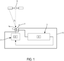
- the figure 1 illustrates a system for tracking the pointing of an antenna 1 towards a mobile communication device, for example a satellite S.
- the satellite S is typically geostationary and is typically a telecommunications satellite.
- the communication mobile or satellite S advantageously transmits a radio signal on a continuous carrier (that is to say such that its transmission power is constant) amplitude / phase modulated by a random message, in a given frequency band .
- Antenna 1 belongs to a ground station of known type.
- antenna 1 points towards the satellite S along an antenna axis 1a.
- Antenna axis 1a forms an angle x with satellite S. This angle x is the angular offset of antenna 1.
- Antenna axis 1a is typically defined as the direction in the antenna frame where the gain of the latter is maximum.
- the antenna axis 1a is motorized by a motor 2 which receives instructions from a device 3 for determining the pointing of the antenna.
- the device 3 for determining the pointing of the antenna 1 is capable of estimating an angular displacement of the antenna from which an antenna pointing setpoint is generated to be communicated to the motor 21.
- Such a measuring device comprises a processor 31 configured to implement a method for estimating the deflection and a method for tracking the aim described in relation to the figure 2 .
- a periodic depointing movement and controlled kinematics is applied to the antenna axis 1a by means of an antenna control unit 2 comprising a motor 21.
- This periodic trajectory has an amplitude x1 and a pulsation ⁇ .
- It can be sinusoidal, ellipsoidal, etc.
- the antenna 1 receives (step E1) radio frequency signals.
- the signals are received for a duration which corresponds to the period of the depointing movement.
- the signal is received on a frequency band less than or equal to the frequency of the signal emitted by the mobile. This makes it possible to recover the signal more easily since the frequency spectrum corresponds to that of the emission.
- step E2 These received signals are converted (step E2) into complex signals of real and imaginary components, respectively I and Q, digital, in baseband.
- step E3 a preprocessing (step E3) of the signals I and Q is carried out. At the end of this preprocessing step, the instantaneous power of the signal is obtained.
- This preprocessing comprises an identical baseband filtering of each I & Q channel (steps E31 and E32), of width less than or equal to that of the signals received, then a measurement of the instantaneous rms voltage (step E33), then a filtering narrow-band video (step E34) and finally a calculation (step E35) of the power of the signal defined in a logarithmic scale is carried out on the basis of this rms voltage.
- Narrow band filtering is implemented by means of a filter having a cutoff frequency Fc, Fc typically equal to ten Hertz to a few hundred Hertz (typically 100 Hz).
- a harmonic decomposition of the power thus obtained is then carried out (step E4) so as to obtain a fundamental component H1 and at least one harmonic component 2 of interest noted H2, or even a DC component noted H0.
- Harmonic decomposition is carried out by calculating correlation products over a period between the detected power and the corresponding harmonic of the depointing movement.
- the DC component H0 is therefore obtained by calculating the average of the signal obtained at the end of the chain E3 over a period of the depointing cycle. This average is representative of the average signal power received from the mobile.
- the fundamental component H1 is obtained by calculating over a period the correlation product (step E41) between the signal obtained at the end of the chain E3 and the function which governed the movement of the antenna around the anticipated direction.
- the harmonic component 2 H2 is obtained by calculating the correlation product (step E42) between the power of the signal and the function cos (2. ⁇ ( t )).
- the angular error x is estimated (step E5) from the values of H0, H1 and H2, or even H3 or a higher order, the values of which have previously been established by an analytical calculation as a function of the error x, the periodic depointing amplitude x 1 , the antenna lobe width at -3dB x 0 and the signal-to-noise ratio in the baseband S / N.
- This estimate ⁇ x> can be compared with a threshold S1 (step E6). If the angular shifting is greater than or equal to this threshold S1, then the transmission is ordered (step E8) from the antenna to the mobile or the satellite if the latter is transmitting. Otherwise the transmission continues (step E7). These decisions are communicated to the control unit of antenna 2.
- the 2 H2 harmonic can be compared with two thresholds S2 and S3 (step E9). If the 2 H2 harmonic is between the two thresholds (that is to say S2 ⁇ H2 ⁇ S3) then a re-pointing setpoint - ⁇ x> is determined (step E10). Otherwise, no compensation is performed (step E11). Here again, these decisions are communicated to the control unit of antenna 2.
- the setpoint compensates for the angular offset calculated so that the antenna points correctly towards the satellite.
- ratio x / x 1 is proportional to the quotient of the fundamental 1 and harmonic 2 components, linked to this quotient by a fixed constant depending only on the amplitude of the movement carried out independent of the signal to noise ratio.
- the ratio between the fundamental and the 2 harmonic is independent of the signal to noise ratio.
- the ratio is independent of the logarithmic conversion scale used (natural, base 10, 2 or other ).
- this proportionality is no longer exact if we have not expressed the powers H1 and H2 by a logarithmic scale.
- the logarithmic conversion is therefore not used here according to an engineering convention but because it is a process which makes it possible to obtain the correct offset value, without there being any need for calibration or determination of 'a gain in proportionality, nor correction of linearity defect.
Landscapes
- Engineering & Computer Science (AREA)
- Computer Networks & Wireless Communication (AREA)
- Signal Processing (AREA)
- Radar, Positioning & Navigation (AREA)
- Remote Sensing (AREA)
- Physics & Mathematics (AREA)
- General Physics & Mathematics (AREA)
- Power Engineering (AREA)
- Variable-Direction Aerials And Aerial Arrays (AREA)
Description
- L'invention concerne un procédé et un dispositif d'estimation précis du dépointage angulaire d'une antenne de réception de télécommunications. Cette information permet essentiellement de prendre une décision relative au respect de normes relatives au rayonnement hors axe quand l'antenne est aussi émettrice.
- Les stations de télécommunications au sol sont en communication avec des dispositifs mobiles tels que des satellites par l'intermédiaire d'une antenne. Cette antenne doit être correctement pointée vers le mobile pour assurer une bonne qualité de communication sans perturber les autres utilisateurs travaillant dans la même bande de fréquence sur le lien montant.
- Au cours de la communication, le mobile peut dériver, ou bien le porteur sur lequel est assise l'antenne peut être mobile et soumis à des mouvements de sorte que l'antenne n'est plus correctement pointée vers le mobile.
- Outre la dégradation de la communication un tel dépointage peut entrainer la réception de signaux non désirés ou bien perturber les communications relayées par des dispositifs de communication adjacents ou bien des satellites adjacents quand l'antenne est aussi émettrice.
- Aussi, il existe des solutions pour, d'une part estimer le dépointage de l'antenne et, pour d'autre part, repointer l'antenne correctement afin de compenser le dépointage estimé. Dans ce dernier cas, on parle alors de poursuite du pointage ou d'écartométrie constituée sous la forme d'une boucle d'asservissement.
- La mesure de dépointage angulaire la plus populaire et la moins chère se fait par une technique dite de « Step-Track » ou « Track While Scan». A ce titre, on pourra se référer aux documents
US 6 433 736 etUS 7 633 432 . - Cette technique comprend l'application à l'antenne d'un mouvement prédéfini de dépointage de faible amplitude (en anglais, « dithering movement ») autour de la direction anticipée de l'émetteur (le satellite ou le mobile). Un récepteur mesure la variation de niveau de signal reçu au long de cette trajectoire et, selon son profil, estime une grandeur proportionnelle à l'angle de dépointage par rapport à cette direction anticipée.
- Dans ce cas, le récepteur le plus simple possible est dit « non cohérent » et calcule directement la puissance instantanée du signal reçu dans sa bande passante sans le démoduler.
- Le problème est qu'une telle technique est très sensible au rapport signal-à-bruit, elle fournit notamment une réponse dont le facteur d'échelle ou gain (ratio de la réponse de puissance par le dépointage) dépend de cette valeur. On rencontre alors deux inconvénients majeurs pour les systèmes d'antenne intégrant cette solution.
- Le premier est qu'on ne sait pas déterminer si on a dépassé l'erreur de pointage maximale autorisée réglementairement pour pouvoir émettre. L'équipement pourrait alors se voir refuser les certifications requises pour être diffusé sur le marché.
- Le second est que l'on commet une erreur importante de synthèse de la fonction de transfert pour la boucle d'asservissement de la poursuite. Au mieux, la bande passante de poursuite s'en trouve très réduite (gain plus faible qu'estimé), au pire la poursuite devient carrément instable et l'équipement est inutilisable (gain plus fort qu'estimé).
- Ces difficultés sont de plus en plus critiques car les nouvelles techniques de communication (à étalement de spectre, à codage de l'information de plus en plus sophistiqué) exigent de pouvoir fonctionner avec des rapports signaux-à-bruit très faibles voire négatifs (exprimés en décibels). Dans ce cas, la valeur S / (S+N) s'écarte fortement de 1 et le gain s'en retrouve très fortement réduit.
- La demande de brevet
US 2 638 585 A divulgue un exemple d'un procédé d'estimation du dépointage. Dans cette estimation, une analyse est faite sur l'harmonique d'un signal reçu en utilisant le rapport entre un terme fondamental et un terme harmonique. - L'invention propose de pallier les inconvénients précités.
- A cet effet, selon un premier aspect, l'invention propose un procédé d'estimation du dépointage angulaire x d'une antenne pointant vers un satellite ou un mobile éloigné selon un axe d'antenne, l'antenne étant en communication radio avec ce satellite ou ce mobile le satellite ou le mobile émettant sur une porteuse continue modulée en amplitude/phase par un mssage, dans une bande de fréquence donnée, le procédé comprenant des étapes suivantes :
- application d'un mouvement périodique prédéfini à l'axe d'antenne ;
- réception de signaux radiofréquences issus du satellite ou du mobile, pendant une durée qui correspond à une période du mouvement appliqué, le signal étant reçu sur une bande de fréquence inférieure ou égale à la fréquence du signal émis ;
- détermination sur une échelle logarithmique de la puissance instantanée du signal reçu, ladite puissance instantanée étant obtenue au moyen des étapes suivantes :
- filtrage du signal en fréquence intermédiaire ou en bande de base de tout ou partie du spectre du signal parvenant du satellite ou du mobile
- calcul de la tension efficace du signal radiofréquence reçu ;
- filtrage de cette tension efficace ;
- calcul du logarithme de cette tension efficace filtrée ;
- décomposition harmonique sur chaque période de la puissance ainsi déterminée en une composante fondamentale et au moins une composante harmonique ;
- estimation du dépointage angulaire x définit par le rapport de la composante fondamentale sur une composante harmonique.
- L'invention est avantageusement complétée par les caractéristiques suivantes, prises seules ou en une quelconque de leur combinaison techniquement possible.
- La composante harmonique d'intérêt est la composante harmonique 2 (H2), l'estimation du dépointage angulaire x étant obtenu à partir du ratio de la composante fondamentale sur la composante harmonique 2.
- Le mouvement est de type sinusoïdal ou composition 2D de mouvements élémentaires sur 2 axes orthogonaux de types sinusoïdaux de préférence elliptiques ou Lissajous.
- Selon un deuxième aspect, l'invention se rapporte à un procédé de poursuite du pointage d'une antenne, une étape de mesure du dépointage angulaire de l'antenne au moyen d'un procédé d'estimation selon l'invention, ledit procédé comprenant une étape de
- comparaison du dépointage à un seuil, et
- si le dépointage est supérieur au dit seuil, le procédé comprenant une étape d'arrêt de l'émission de l'antenne vers le satellite ou le mobile si l'antenne est aussi
- Le procédé selon le deuxième aspect de l'invention peut comprendre une étape de comparaison de l'harmonique 2 à deux valeurs de seuils, et si ladite harmonique 2 est comprise entre lesdites deux valeurs de seuil, le procédé comprend une étape de génération d'une consigne de déplacement de l'antenne pour annuler le dépointage estimé.
- Selon un troisième aspect, l'invention concerne un dispositif de mesure précise de l'erreur de pointage angulaire d'une antenne comprenant un processeur configuré pour mettre en œuvre un procédé selon le premier aspect de l'invention.
- Selon un quatrième aspect, l'invention concerne un dispositif de poursuite du pointage d'une antenne comprenant une unité de commande de l'antenne et un dispositif d'estimation du dépointage angulaire de l'antenne selon le troisième aspect de l'invention et comprenant un processeur configuré pour mettre en œuvre un procédé selon le deuxième aspect de l'invention.
- D'autres caractéristiques, buts et avantages de l'invention ressortiront de la description qui suit, qui est purement illustrative et non limitative, et qui doit être lue en regard des dessins annexés sur lesquels :
- la
figure 1 illustre un schéma contextuel de l'invention comprenant un dispositif de poursuite pointage d'une antenne ; - la
figure 2 illustre des étapes de procédé de détermination du pointage de l'antenne selon l'invention - Sur l'ensemble des figures les éléments similaires portent des références identiques.
- La
figure 1 illustre un système de poursuite du pointage d'une antenne 1 vers un dispositif mobile de communication, par exemple un satellite S. Le satellite S est typiquement géostationnaire et est typiquement un satellite de télécommunication. - Le mobile de communication ou satellite S émet avantageusement un signal radio sur une porteuse continue (c'est-à-dire tel que sa puissance d'émission soit constante) modulée en amplitude/phase par un message aléatoire, dans une bande de fréquence donnée.
- L'antenne 1 appartient à une station sol de type connue.
- On considère que l'antenne 1 pointe vers le satellite S selon un axe 1a d'antenne. L'axe 1a d'antenne forme un angle x avec le satellite S. Cet angle x est le dépointage angulaire de l'antenne 1. L'axe 1a de l'antenne est typiquement défini comme la direction dans le repère antenne où le gain de cette dernière est maximum.
- L'axe 1a d'antenne est motorisé par un moteur 2 qui reçoit des consignes d'un dispositif 3 de détermination du pointage de l'antenne.
- Le dispositif 3 de détermination du pointage de l'antenne 1 est capable d'estimer un dépointage angulaire de l'antenne à partir duquel une consigne de pointage de l'antenne est générée pour être communiquée au moteur 21.
- Un tel dispositif de mesure comprend un processeur 31 configuré pour mettre en œuvre un procédé d'estimation du dépointage et un procédé de poursuite du pointage décrits en relation avec la
figure 2 . - Dans une étape préliminaire (étape E0) un mouvement de dépointage périodique et de cinématique maîtrisée est appliqué à l'axe 1a d'antenne par l'intermédiaire d'une unité 2 de commande de l'antenne comprenant un moteur 21. Cette trajectoire périodique a une amplitude x1 et une pulsation ω.
- Il peut s'agit d'un mouvement sinusoïdal, ellipsoïdal, etc.
- L'antenne 1 reçoit (étape E1) des signaux radio fréquences. Les signaux sont reçus pendant une durée qui correspond à la période du mouvement de dépointage.
- En outre, le signal est reçu sur une bande de fréquences inférieure ou égale à la fréquence du signal émis par le mobile. Ceci permet de récupérer plus facilement le signal puisque le spectre de fréquences correspond à celui de l'émission.
- Ces signaux reçus sont convertis (étape E2) en signaux complexes de composantes réelles et imaginaires respectivement I et Q, numériques, en bande de base.
- Ensuite, un prétraitement (étape E3) des signaux I et Q est effectué. A l'issue de cette étape de prétraitement, la puissance instantanée du signal est obtenue.
- Ce prétraitement comprend un filtrage en bande de base identique de chaque voie I & Q (étapes E31 et E32), de largeur inférieure ou égale à celle des signaux reçus, puis une mesure de la tension efficace instantanée (étape E33), puis un filtrage vidéo (étape E34) en bande étroite et enfin un calcul (étape E35) de la puissance du signal définie dans une échelle logarithmique est effectué à partir de cette tension efficace.
- La puissance instantanée en décibels est fonction du logarithme de la tension efficace correspondant à une constante près au logarithme de la puissance logarithmique (E35) de la tension efficace filtrée :

- Le filtrage bande étroite est mis en œuvre au moyen d'un filtre ayant une fréquence de coupure Fc, Fc valant typiquement la dizaine de Hertz à quelques centaines de Hertz (typiquement 100 Hz).
- Une décomposition harmonique de la puissance ainsi obtenue est ensuite effectuée (étape E4) de manière à obtenir une composante fondamentale H1 et au moins une composante harmonique 2 d'intérêt notée H2, voire une composante continue notée H0.
- La décomposition harmonique s'effectue en calculant des produits de corrélation sur une période entre la puissance détectée et l'harmonique correspondante du mouvement de dépointage.
- La composante continue H0 est donc obtenue en calculant la moyenne du signal obtenu en bout de la chaîne E3 sur une période du cycle de dépointage. Cette moyenneest représentative de la puissance moyenne de signal reçue du mobile.
- La composante fondamentale H1 est obtenue en calculant sur une période le produit de corrélation (étape E41) entre le signal obtenu en bout de chaîne E3 et la fonction ayant régi le mouvement de l'antenne autour de la direction anticipée.
- Dans le cas d'un mouvement sinusoïdal appliqué à l'antenne la corrélation se fait avec la fonction x1.sin(ω(t)).
- La composante harmonique 2 H2 est obtenue en calculant le produit de corrélation (étape E42) entre la puissance du signal et la fonction cos(2. ω(t)).
- Il est possible d'estimer en plus les harmoniques d'ordres supérieures comme H3, H4, etc..., ce qui permet potentiellement d'affiner les précisions de calcul de dépointage menés à l'étape suivante.
- Ensuite, on estime l'erreur angulaire x (étape E5) à partir des valeurs de H0, H1 et H2, voire H3 ou un ordre supérieur, dont on a préalablement établi les valeurs par un calcul analytique en fonction de l'erreur x, de l'amplitude de dépointage périodique x1, de la largeur du lobe d'antenne à -3dB x0 et du rapport signal à bruit dans la bande de base S/N.
- En particulier, ces calculs montrent que le rapport des composantes H1/H2 constitue un estimateur <x> de l'erreur x indépendant de la valeur de rapport du signal à bruit et de la largeur du lobe, ce qui fournit la réalisation la plus simple de l'étape d'estimation E5.
- Cet estimé <x> peut être comparée à un seuil S1 (étape E6). Si le dépointage angulaire est supérieur ou égal à ce seuil S1 alors on commande (étape E8) l'arrêt de l'émission de l'antenne vers le mobile ou le satellite si cette dernière est émettrice. Sinon l'émission continue (étape E7). Ces décisions sont communiquées à l'unité de commande de l'antenne 2.
- De manière alternative ou complémentaire, l'harmonique 2 H2 peut être comparée à deux seuils S2 et S3 (étape E9). Si l'harmonique 2 H2 est comprise entre les deux seuils (c'est-à-dire S2 ≤ H2 ≤ S3) alors une consigne de re-pointage -<x> est déterminée (étape E10). Dans le cas contraire, aucune compensation n'est effectuée (étape E11). Là encore ces décisions sont communiquées à l'unité de commande de l'antenne 2.
- La consigne permet de compenser le dépointage angulaire calculé pour que l'antenne pointe correctement vers le satellite.
- Ci-dessous on démontre que le ratio x/x1 est proportionnel au quotient des composantes fondamentale 1 et harmonique 2, relié à ce quotient par une constante fixe ne dépendant que de l'amplitude du mouvement effectué indépendante du rapport signal à bruit.
- Soit une antenne 1 ayant des dimensions supérieures à 10.λ (avec λ la longueur d'onde des signaux radiofréquences reçus par l'antenne).
- L'antenne possède un gain d'antenne :

- En considérant un mouvement périodique d'équation x1. sin ω(t) appliqué à l'antenne 1 (l'antenne étant soumise à un mouvement x1. sin ω(t) + x) on a

- En notant S comme la puissance moyenne de signal utile reçue par l'antenne pointée dans l'axe et N le bruit fixe recueilli dans toute la bande de base, on calcule la puissance moyenne du signal reçu (en décibels) W(dB) obtenue à l'issue de l'étape de pré-traitement (étape E2) qui est donnée par :


- Si S<N et si les mouvements d'antenne sont de faible amplitude autour de son axe on a alors l'approximation :


- Soit l'expression du terme fondamental H1 donné par l'expression suivante

- L'harmonique 2 H2 est donnée par la corrélation de la puissance du signal reçu avec un terme cosinus calculé sur une période entre 0 et 2π, soit :

- On obtient alors le rapport :

- On constate que le rapport entre le fondamental et l'harmonique 2 est indépendant du rapport signal à bruit. On remarque aussi que le rapport est indépendant de l'échelle de conversion logarithmique utilisée (népérien, base 10, 2 ou autre...). En revanche, cette proportionnalité n'est plus exacte si l'on n'a pas exprimé les puissances H1 et H2 par une échelle logarithmique. La conversion logarithmique n'est donc pas ici utilisée selon une convention d'ingénieur mais bien parce que c'est un procédé qui permet d'obtenir une la valeur correcte de dépointage, sans qu'il y ait besoin de calibrage ni de détermination d'un gain de proportionnalité, ni de correction de défaut de linéarité.
- Bien entendu, ces qualités demeurent valables pour tout type de trajectoire appliquée à l'antenne 1 présentant une périodicité, quels que soient la taille du lobe d'antenne, l'amplitude du mouvement de recherche x1, l'erreur axiale de pointage x.
- L'estimateur <x> est donc défini par la fonctionnelle suivante :

Claims (7)
- Procédé d'estimation du dépointage angulaire x d'une antenne (1) pointant vers un satellite ou un mobile éloigné (S) selon un axe d'antenne (1a), l'antenne étant en communication radio avec ce satellite ou ce mobile (S), le satellite ou le mobile émettant sur une porteuse continue modulée en amplitude/phase par un message, dans une bande de fréquence donnée, le procédé comprenant des étapes suivantes :- application (E0) d'un mouvement périodique prédéfini à l'axe d'antenne (1a) ;- réception (E1) de signaux radiofréquences issus du satellite ou du mobile pendant une durée qui correspond à une période du mouvement appliqué, le signal étant reçu sur une bande de fréquence inférieure ou égale à la fréquence du signal émis ;- détermination (E3) sur une échelle logarithmique de la puissance instantanée du signal reçu, ladite puissance instantanée étant obtenue au moyen des étapes suivantes :- filtrage du signal en fréquence intermédiaire ou en bande de base (E31, E32) de tout ou partie du spectre du signal parvenant du satellite ou du mobile;- calcul (E33) de la tension efficace du signal radiofréquence reçu;- filtrage (E34) de cette tension efficace ;- calcul du logarithme de cette tension efficace filtrée ;- décomposition (E4) harmonique sur chaque période de la puissance ainsi déterminée en une composante fondamentale (H1) et au moins une composante harmonique ;- estimation (E5) du dépointage angulaire x définit par le rapport de la composante fondamentale sur une composante harmonique.
- Procédé selon la revendication 1, dans lequel la composante harmonique d'intérêt est la composante harmonique 2 (H2), l'estimation du dépointage angulaire x étant obtenu à partir du ratio de la composante fondamentale sur la composante harmonique 2.
- Procédé selon l'une des revendications précédentes, dans lequel le mouvement est de type sinusoïdal ou composition 2D de mouvements élémentaires sur 2 axes orthogonaux de types sinusoïdaux de préférence elliptiques ou Lissajous.
- Procédé de poursuite du pointage d'une antenne, comprenant une étape d'estimation du dépointage angulaire de l'antenne au moyen d'un procédé d'estimation selon l'une des revendications 1 à 3, le procédé comprenant une étape de comparaison (E6) du dépointage à un seuil (S1) ; et si le dépointage est supérieur au dit seuil, le procédé comprenant une étape d'arrêt (E7) de l'émission de l'antenne vers le satellite ou le mobile si l'antenne est aussi émettrice
- Procédé de poursuite du pointage d'une antenne selon la revendication 4, comprenant une étape de comparaison (E9) de l'harmonique 2 (H2) à deux valeurs de seuils (S2, 3), et si ladite harmonique 2 (H2) est comprise entre lesdites deux valeurs de seuil, le procédé comprenant une étape de génération (E10) d'une consigne de déplacement de l'antenne pour annuler le dépointage estimé.
- Dispositif de mesure précise du dépointage angulaire d'une antenne comprenant un processeur configuré pour mettre en œuvre un procédé selon l'une des revendications 1 à 3.
- Dispositif de poursuite du pointage d'une antenne comprenant une unité (2) de commande de l'antenne (1) et un dispositif d'estimation du dépointage angulaire de l'antenne selon la revendication 8 comprenant un processeur configuré pour mettre en œuvre un procédé selon l'une des revendications 4 à 5.
Applications Claiming Priority (2)
| Application Number | Priority Date | Filing Date | Title |
|---|---|---|---|
| FR1758000A FR3070548B1 (fr) | 2017-08-30 | 2017-08-30 | Procede et dispositif d'estimation du depointage d'une antenne et procede et dispositif de poursuite du pointage d'une antenne mettant en oeuvre de tels procede et dispositif, fondes sur une analyse harmonique |
| PCT/EP2018/073384 WO2019043117A1 (fr) | 2017-08-30 | 2018-08-30 | Procédé et dispositif d'estimation du dépointage d'une antenne et procédé et dispositif de poursuite du pointage d'une antenne mettant en oeuvre de tels procédé et dispositif, fondés sur une analyse harmonique |
Publications (2)
| Publication Number | Publication Date |
|---|---|
| EP3676967A1 EP3676967A1 (fr) | 2020-07-08 |
| EP3676967B1 true EP3676967B1 (fr) | 2021-05-12 |
Family
ID=60627764
Family Applications (1)
| Application Number | Title | Priority Date | Filing Date |
|---|---|---|---|
| EP18758904.9A Active EP3676967B1 (fr) | 2017-08-30 | 2018-08-30 | Procédé et dispositif d'estimation du dépointage d'une antenne et procédé et dispositif de poursuite du pointage d'une antenne mettant en oeuvre de tels procédé et dispositif, fondés sur une analyse harmonique |
Country Status (7)
| Country | Link |
|---|---|
| US (1) | US11303017B2 (fr) |
| EP (1) | EP3676967B1 (fr) |
| KR (1) | KR102487419B1 (fr) |
| CN (1) | CN111512569B (fr) |
| FR (1) | FR3070548B1 (fr) |
| IL (1) | IL272968A (fr) |
| WO (1) | WO2019043117A1 (fr) |
Families Citing this family (1)
| Publication number | Priority date | Publication date | Assignee | Title |
|---|---|---|---|---|
| FR3119272B1 (fr) * | 2021-01-28 | 2022-12-23 | Safran Data Systems | Procédé et système de contrôle d’une antenne dans un système de communications par satellite |
Family Cites Families (15)
| Publication number | Priority date | Publication date | Assignee | Title |
|---|---|---|---|---|
| US2638585A (en) * | 1947-09-02 | 1953-05-12 | Hughes Tool Co | Radio-locator system |
| US3947848A (en) * | 1962-08-07 | 1976-03-30 | The United States Of America As Represented By The Secretary Of The Navy | Anti-jam dual channel video cancellation circuit for first target tracking system |
| US5043737A (en) * | 1990-06-05 | 1991-08-27 | Hughes Aircraft Company | Precision satellite tracking system |
| US5093649A (en) * | 1990-08-28 | 1992-03-03 | The Boeing Company | Bessel beam radar system using sequential spatial modulation |
| US5351060A (en) | 1991-02-25 | 1994-09-27 | Bayne Gerald A | Antenna |
| CN1139204C (zh) * | 1998-05-20 | 2004-02-18 | Ntt移动通信网株式会社 | 防止干扰的无线通信系统 |
| US6925108B1 (en) * | 2000-05-26 | 2005-08-02 | Freescale Semiconductor, Inc. | Ultrawide bandwidth system and method for fast synchronization |
| US6433736B1 (en) | 2000-11-22 | 2002-08-13 | L-3 Communications Corp. | Method and apparatus for an improved antenna tracking system mounted on an unstable platform |
| US7397422B2 (en) * | 2006-09-19 | 2008-07-08 | The Boeing Company | Method and system for attitude determination of a platform using global navigation satellite system and a steered antenna |
| US7633432B2 (en) | 2006-12-13 | 2009-12-15 | The Boeing Company | Method and apparatus for precision antenna boresight error estimates |
| FR2985121B1 (fr) * | 2011-12-22 | 2014-01-17 | Astrium Sas | Procede et systeme d'estimation d'une difference de marche d'un signal cible emis par un engin en orbite terrestre ou aerien |
| CN103916201B (zh) * | 2014-03-26 | 2015-12-02 | 中国科学院国家天文台 | 一种天线信号初始相位差、时延和频率差估计装置与方法 |
| FR3040838B1 (fr) * | 2015-09-04 | 2017-09-22 | Turbomeca | Generateur magnetohydrodynamique |
| CN106597473A (zh) * | 2015-12-22 | 2017-04-26 | 中国电子科技集团公司第二十研究所 | 一种用于站间卫星通信的天线跟踪和自校准的装置及方法 |
| CN107070526B (zh) * | 2016-12-30 | 2020-11-06 | 南京理工大学 | 低轨星载智能天线接收系统及方法 |
-
2017
- 2017-08-30 FR FR1758000A patent/FR3070548B1/fr not_active Expired - Fee Related
-
2018
- 2018-08-30 KR KR1020207009246A patent/KR102487419B1/ko active Active
- 2018-08-30 WO PCT/EP2018/073384 patent/WO2019043117A1/fr not_active Ceased
- 2018-08-30 EP EP18758904.9A patent/EP3676967B1/fr active Active
- 2018-08-30 CN CN201880056910.8A patent/CN111512569B/zh not_active Expired - Fee Related
- 2018-08-30 US US16/643,182 patent/US11303017B2/en not_active Expired - Fee Related
-
2020
- 2020-02-27 IL IL272968A patent/IL272968A/en unknown
Also Published As
| Publication number | Publication date |
|---|---|
| US20200212564A1 (en) | 2020-07-02 |
| FR3070548B1 (fr) | 2019-09-13 |
| WO2019043117A1 (fr) | 2019-03-07 |
| KR20200107924A (ko) | 2020-09-16 |
| CN111512569A (zh) | 2020-08-07 |
| EP3676967A1 (fr) | 2020-07-08 |
| KR102487419B1 (ko) | 2023-01-11 |
| FR3070548A1 (fr) | 2019-03-01 |
| IL272968A (en) | 2020-04-30 |
| CN111512569B (zh) | 2023-05-02 |
| US11303017B2 (en) | 2022-04-12 |
Similar Documents
| Publication | Publication Date | Title |
|---|---|---|
| EP3026453B1 (fr) | Procede de generation d'une cartographie de couverture d'emission ou de reception d'une antenne d'une station sol pour des liaisons satellite | |
| FR2679085A1 (fr) | Systeme et procede de calcul du gain de canal et de la variance du bruit d'un canal de communication. | |
| EP2580880B1 (fr) | Procede et systeme de transmission optique par signaux laser en champ libre | |
| EP2533426B1 (fr) | Système de réception comprenant un mécanisme contre les interférences pulsées | |
| FR3070548B1 (fr) | Procede et dispositif d'estimation du depointage d'une antenne et procede et dispositif de poursuite du pointage d'une antenne mettant en oeuvre de tels procede et dispositif, fondes sur une analyse harmonique | |
| EP2715392B1 (fr) | Procede de localisation d'un terminal a la surface d'une zone de couverture au moyen d'un reseau de telecommunication utilisant un satellite multifaisceaux | |
| EP3560114B1 (fr) | Transmission optique à partir d'un satellite à destination d'un terminal de réception | |
| US11489590B1 (en) | Optical link and coherent receiver noise characterization | |
| EP3907895A1 (fr) | Méthode de réception d'un signal modulé et récepteur associé | |
| EP2932624B1 (fr) | Recepteur de signaux radiofrequence destine a etre installe sur un satellite | |
| EP1112630B1 (fr) | Procede d'estimation du rapport signal a bruit dans un recepteur de telecommunications et application de ce procede au controle d'un emetteur | |
| EP2629439B1 (fr) | Procédé de génération d'un diagramme d'émission ou de réception d'une antenne d'un satellite | |
| FR3166261A1 (fr) | Systeme pour recevoir un signal satellitaire | |
| EP2637375B1 (fr) | Procede et recepteur pour supprimer un signal de brouillage a controle automatique numerique du seuil de decision | |
| Nunes et al. | M-DPSK detection, channel estimation and power control in LEO satellite communications | |
| FR3119272A1 (fr) | Procédé et système de contrôle d’une antenne dans un système de communications par satellite | |
| FR3105833A1 (fr) | Procede anti-geolocalisation d'un premier terminal de telecommunication par satellite, dispositif et programme d'ordinateur associes | |
| FR2960721A1 (fr) | Procède et dispositif permettant de réaliser le codage analogique-numérique de signaux hyperfréquence de très grande dynamique présentant une grande bande passante |
Legal Events
| Date | Code | Title | Description |
|---|---|---|---|
| STAA | Information on the status of an ep patent application or granted ep patent |
Free format text: STATUS: UNKNOWN |
|
| STAA | Information on the status of an ep patent application or granted ep patent |
Free format text: STATUS: THE INTERNATIONAL PUBLICATION HAS BEEN MADE |
|
| PUAI | Public reference made under article 153(3) epc to a published international application that has entered the european phase |
Free format text: ORIGINAL CODE: 0009012 |
|
| STAA | Information on the status of an ep patent application or granted ep patent |
Free format text: STATUS: REQUEST FOR EXAMINATION WAS MADE |
|
| 17P | Request for examination filed |
Effective date: 20200320 |
|
| AK | Designated contracting states |
Kind code of ref document: A1 Designated state(s): AL AT BE BG CH CY CZ DE DK EE ES FI FR GB GR HR HU IE IS IT LI LT LU LV MC MK MT NL NO PL PT RO RS SE SI SK SM TR |
|
| AX | Request for extension of the european patent |
Extension state: BA ME |
|
| DAV | Request for validation of the european patent (deleted) | ||
| DAX | Request for extension of the european patent (deleted) | ||
| RIC1 | Information provided on ipc code assigned before grant |
Ipc: H01Q 3/10 20060101ALI20201222BHEP Ipc: H01Q 3/26 20060101ALI20201222BHEP Ipc: H04B 7/06 20060101AFI20201222BHEP |
|
| GRAP | Despatch of communication of intention to grant a patent |
Free format text: ORIGINAL CODE: EPIDOSNIGR1 |
|
| STAA | Information on the status of an ep patent application or granted ep patent |
Free format text: STATUS: GRANT OF PATENT IS INTENDED |
|
| INTG | Intention to grant announced |
Effective date: 20210204 |
|
| GRAS | Grant fee paid |
Free format text: ORIGINAL CODE: EPIDOSNIGR3 |
|
| GRAA | (expected) grant |
Free format text: ORIGINAL CODE: 0009210 |
|
| STAA | Information on the status of an ep patent application or granted ep patent |
Free format text: STATUS: THE PATENT HAS BEEN GRANTED |
|
| AK | Designated contracting states |
Kind code of ref document: B1 Designated state(s): AL AT BE BG CH CY CZ DE DK EE ES FI FR GB GR HR HU IE IS IT LI LT LU LV MC MK MT NL NO PL PT RO RS SE SI SK SM TR |
|
| REG | Reference to a national code |
Ref country code: GB Ref legal event code: FG4D Free format text: NOT ENGLISH |
|
| REG | Reference to a national code |
Ref country code: CH Ref legal event code: EP |
|
| REG | Reference to a national code |
Ref country code: DE Ref legal event code: R096 Ref document number: 602018017082 Country of ref document: DE |
|
| REG | Reference to a national code |
Ref country code: IE Ref legal event code: FG4D Free format text: LANGUAGE OF EP DOCUMENT: FRENCH |
|
| REG | Reference to a national code |
Ref country code: AT Ref legal event code: REF Ref document number: 1392875 Country of ref document: AT Kind code of ref document: T Effective date: 20210615 |
|
| REG | Reference to a national code |
Ref country code: LT Ref legal event code: MG9D |
|
| REG | Reference to a national code |
Ref country code: NO Ref legal event code: T2 Effective date: 20210512 |
|
| REG | Reference to a national code |
Ref country code: AT Ref legal event code: MK05 Ref document number: 1392875 Country of ref document: AT Kind code of ref document: T Effective date: 20210512 |
|
| PG25 | Lapsed in a contracting state [announced via postgrant information from national office to epo] |
Ref country code: LT Free format text: LAPSE BECAUSE OF FAILURE TO SUBMIT A TRANSLATION OF THE DESCRIPTION OR TO PAY THE FEE WITHIN THE PRESCRIBED TIME-LIMIT Effective date: 20210512 Ref country code: HR Free format text: LAPSE BECAUSE OF FAILURE TO SUBMIT A TRANSLATION OF THE DESCRIPTION OR TO PAY THE FEE WITHIN THE PRESCRIBED TIME-LIMIT Effective date: 20210512 Ref country code: FI Free format text: LAPSE BECAUSE OF FAILURE TO SUBMIT A TRANSLATION OF THE DESCRIPTION OR TO PAY THE FEE WITHIN THE PRESCRIBED TIME-LIMIT Effective date: 20210512 Ref country code: AT Free format text: LAPSE BECAUSE OF FAILURE TO SUBMIT A TRANSLATION OF THE DESCRIPTION OR TO PAY THE FEE WITHIN THE PRESCRIBED TIME-LIMIT Effective date: 20210512 Ref country code: BG Free format text: LAPSE BECAUSE OF FAILURE TO SUBMIT A TRANSLATION OF THE DESCRIPTION OR TO PAY THE FEE WITHIN THE PRESCRIBED TIME-LIMIT Effective date: 20210812 |
|
| PG25 | Lapsed in a contracting state [announced via postgrant information from national office to epo] |
Ref country code: GR Free format text: LAPSE BECAUSE OF FAILURE TO SUBMIT A TRANSLATION OF THE DESCRIPTION OR TO PAY THE FEE WITHIN THE PRESCRIBED TIME-LIMIT Effective date: 20210813 Ref country code: IS Free format text: LAPSE BECAUSE OF FAILURE TO SUBMIT A TRANSLATION OF THE DESCRIPTION OR TO PAY THE FEE WITHIN THE PRESCRIBED TIME-LIMIT Effective date: 20210912 Ref country code: PL Free format text: LAPSE BECAUSE OF FAILURE TO SUBMIT A TRANSLATION OF THE DESCRIPTION OR TO PAY THE FEE WITHIN THE PRESCRIBED TIME-LIMIT Effective date: 20210512 Ref country code: LV Free format text: LAPSE BECAUSE OF FAILURE TO SUBMIT A TRANSLATION OF THE DESCRIPTION OR TO PAY THE FEE WITHIN THE PRESCRIBED TIME-LIMIT Effective date: 20210512 Ref country code: PT Free format text: LAPSE BECAUSE OF FAILURE TO SUBMIT A TRANSLATION OF THE DESCRIPTION OR TO PAY THE FEE WITHIN THE PRESCRIBED TIME-LIMIT Effective date: 20210913 Ref country code: RS Free format text: LAPSE BECAUSE OF FAILURE TO SUBMIT A TRANSLATION OF THE DESCRIPTION OR TO PAY THE FEE WITHIN THE PRESCRIBED TIME-LIMIT Effective date: 20210512 Ref country code: SE Free format text: LAPSE BECAUSE OF FAILURE TO SUBMIT A TRANSLATION OF THE DESCRIPTION OR TO PAY THE FEE WITHIN THE PRESCRIBED TIME-LIMIT Effective date: 20210512 |
|
| PG25 | Lapsed in a contracting state [announced via postgrant information from national office to epo] |
Ref country code: NL Free format text: LAPSE BECAUSE OF FAILURE TO SUBMIT A TRANSLATION OF THE DESCRIPTION OR TO PAY THE FEE WITHIN THE PRESCRIBED TIME-LIMIT Effective date: 20210512 |
|
| PG25 | Lapsed in a contracting state [announced via postgrant information from national office to epo] |
Ref country code: ES Free format text: LAPSE BECAUSE OF FAILURE TO SUBMIT A TRANSLATION OF THE DESCRIPTION OR TO PAY THE FEE WITHIN THE PRESCRIBED TIME-LIMIT Effective date: 20210512 Ref country code: EE Free format text: LAPSE BECAUSE OF FAILURE TO SUBMIT A TRANSLATION OF THE DESCRIPTION OR TO PAY THE FEE WITHIN THE PRESCRIBED TIME-LIMIT Effective date: 20210512 Ref country code: SK Free format text: LAPSE BECAUSE OF FAILURE TO SUBMIT A TRANSLATION OF THE DESCRIPTION OR TO PAY THE FEE WITHIN THE PRESCRIBED TIME-LIMIT Effective date: 20210512 Ref country code: CZ Free format text: LAPSE BECAUSE OF FAILURE TO SUBMIT A TRANSLATION OF THE DESCRIPTION OR TO PAY THE FEE WITHIN THE PRESCRIBED TIME-LIMIT Effective date: 20210512 Ref country code: DK Free format text: LAPSE BECAUSE OF FAILURE TO SUBMIT A TRANSLATION OF THE DESCRIPTION OR TO PAY THE FEE WITHIN THE PRESCRIBED TIME-LIMIT Effective date: 20210512 Ref country code: RO Free format text: LAPSE BECAUSE OF FAILURE TO SUBMIT A TRANSLATION OF THE DESCRIPTION OR TO PAY THE FEE WITHIN THE PRESCRIBED TIME-LIMIT Effective date: 20210512 Ref country code: SM Free format text: LAPSE BECAUSE OF FAILURE TO SUBMIT A TRANSLATION OF THE DESCRIPTION OR TO PAY THE FEE WITHIN THE PRESCRIBED TIME-LIMIT Effective date: 20210512 |
|
| REG | Reference to a national code |
Ref country code: DE Ref legal event code: R097 Ref document number: 602018017082 Country of ref document: DE |
|
| PLBE | No opposition filed within time limit |
Free format text: ORIGINAL CODE: 0009261 |
|
| STAA | Information on the status of an ep patent application or granted ep patent |
Free format text: STATUS: NO OPPOSITION FILED WITHIN TIME LIMIT |
|
| REG | Reference to a national code |
Ref country code: CH Ref legal event code: PL |
|
| PG25 | Lapsed in a contracting state [announced via postgrant information from national office to epo] |
Ref country code: MC Free format text: LAPSE BECAUSE OF FAILURE TO SUBMIT A TRANSLATION OF THE DESCRIPTION OR TO PAY THE FEE WITHIN THE PRESCRIBED TIME-LIMIT Effective date: 20210512 |
|
| 26N | No opposition filed |
Effective date: 20220215 |
|
| REG | Reference to a national code |
Ref country code: BE Ref legal event code: MM Effective date: 20210831 |
|
| PG25 | Lapsed in a contracting state [announced via postgrant information from national office to epo] |
Ref country code: LI Free format text: LAPSE BECAUSE OF NON-PAYMENT OF DUE FEES Effective date: 20210831 Ref country code: CH Free format text: LAPSE BECAUSE OF NON-PAYMENT OF DUE FEES Effective date: 20210831 |
|
| PG25 | Lapsed in a contracting state [announced via postgrant information from national office to epo] |
Ref country code: IS Free format text: LAPSE BECAUSE OF FAILURE TO SUBMIT A TRANSLATION OF THE DESCRIPTION OR TO PAY THE FEE WITHIN THE PRESCRIBED TIME-LIMIT Effective date: 20210912 Ref country code: LU Free format text: LAPSE BECAUSE OF NON-PAYMENT OF DUE FEES Effective date: 20210830 Ref country code: AL Free format text: LAPSE BECAUSE OF FAILURE TO SUBMIT A TRANSLATION OF THE DESCRIPTION OR TO PAY THE FEE WITHIN THE PRESCRIBED TIME-LIMIT Effective date: 20210512 |
|
| PG25 | Lapsed in a contracting state [announced via postgrant information from national office to epo] |
Ref country code: IT Free format text: LAPSE BECAUSE OF FAILURE TO SUBMIT A TRANSLATION OF THE DESCRIPTION OR TO PAY THE FEE WITHIN THE PRESCRIBED TIME-LIMIT Effective date: 20210512 Ref country code: IE Free format text: LAPSE BECAUSE OF NON-PAYMENT OF DUE FEES Effective date: 20210830 Ref country code: BE Free format text: LAPSE BECAUSE OF NON-PAYMENT OF DUE FEES Effective date: 20210831 |
|
| PG25 | Lapsed in a contracting state [announced via postgrant information from national office to epo] |
Ref country code: CY Free format text: LAPSE BECAUSE OF FAILURE TO SUBMIT A TRANSLATION OF THE DESCRIPTION OR TO PAY THE FEE WITHIN THE PRESCRIBED TIME-LIMIT Effective date: 20210512 |
|
| PG25 | Lapsed in a contracting state [announced via postgrant information from national office to epo] |
Ref country code: HU Free format text: LAPSE BECAUSE OF FAILURE TO SUBMIT A TRANSLATION OF THE DESCRIPTION OR TO PAY THE FEE WITHIN THE PRESCRIBED TIME-LIMIT; INVALID AB INITIO Effective date: 20180830 |
|
| PGFP | Annual fee paid to national office [announced via postgrant information from national office to epo] |
Ref country code: NO Payment date: 20230721 Year of fee payment: 6 Ref country code: GB Payment date: 20230720 Year of fee payment: 6 |
|
| PGFP | Annual fee paid to national office [announced via postgrant information from national office to epo] |
Ref country code: FR Payment date: 20230720 Year of fee payment: 6 Ref country code: DE Payment date: 20230720 Year of fee payment: 6 |
|
| PG25 | Lapsed in a contracting state [announced via postgrant information from national office to epo] |
Ref country code: MK Free format text: LAPSE BECAUSE OF FAILURE TO SUBMIT A TRANSLATION OF THE DESCRIPTION OR TO PAY THE FEE WITHIN THE PRESCRIBED TIME-LIMIT Effective date: 20210512 |
|
| PG25 | Lapsed in a contracting state [announced via postgrant information from national office to epo] |
Ref country code: TR Free format text: LAPSE BECAUSE OF FAILURE TO SUBMIT A TRANSLATION OF THE DESCRIPTION OR TO PAY THE FEE WITHIN THE PRESCRIBED TIME-LIMIT Effective date: 20210512 |
|
| PG25 | Lapsed in a contracting state [announced via postgrant information from national office to epo] |
Ref country code: MT Free format text: LAPSE BECAUSE OF FAILURE TO SUBMIT A TRANSLATION OF THE DESCRIPTION OR TO PAY THE FEE WITHIN THE PRESCRIBED TIME-LIMIT Effective date: 20210512 |
|
| REG | Reference to a national code |
Ref country code: DE Ref legal event code: R119 Ref document number: 602018017082 Country of ref document: DE |
|
| GBPC | Gb: european patent ceased through non-payment of renewal fee |
Effective date: 20240830 |
|
| PG25 | Lapsed in a contracting state [announced via postgrant information from national office to epo] |
Ref country code: NO Free format text: LAPSE BECAUSE OF NON-PAYMENT OF DUE FEES Effective date: 20240831 |
|
| PG25 | Lapsed in a contracting state [announced via postgrant information from national office to epo] |
Ref country code: DE Free format text: LAPSE BECAUSE OF NON-PAYMENT OF DUE FEES Effective date: 20250301 |
|
| PG25 | Lapsed in a contracting state [announced via postgrant information from national office to epo] |
Ref country code: GB Free format text: LAPSE BECAUSE OF NON-PAYMENT OF DUE FEES Effective date: 20240830 |
|
| PG25 | Lapsed in a contracting state [announced via postgrant information from national office to epo] |
Ref country code: FR Free format text: LAPSE BECAUSE OF NON-PAYMENT OF DUE FEES Effective date: 20240831 |