EP3676914B1 - Weather protecting (wp) housing for coaxial cable connectors - Google Patents
Weather protecting (wp) housing for coaxial cable connectors Download PDFInfo
- Publication number
- EP3676914B1 EP3676914B1 EP18852122.3A EP18852122A EP3676914B1 EP 3676914 B1 EP3676914 B1 EP 3676914B1 EP 18852122 A EP18852122 A EP 18852122A EP 3676914 B1 EP3676914 B1 EP 3676914B1
- Authority
- EP
- European Patent Office
- Prior art keywords
- iml
- connector
- coaxial cable
- boot
- protective housing
- Prior art date
- Legal status (The legal status is an assumption and is not a legal conclusion. Google has not performed a legal analysis and makes no representation as to the accuracy of the status listed.)
- Active
Links
Images


Classifications
-
- H—ELECTRICITY
- H01—ELECTRIC ELEMENTS
- H01R—ELECTRICALLY-CONDUCTIVE CONNECTIONS; STRUCTURAL ASSOCIATIONS OF A PLURALITY OF MUTUALLY-INSULATED ELECTRICAL CONNECTING ELEMENTS; COUPLING DEVICES; CURRENT COLLECTORS
- H01R13/00—Details of coupling devices of the kinds covered by groups H01R12/70 or H01R24/00 - H01R33/00
- H01R13/46—Bases; Cases
- H01R13/52—Dustproof, splashproof, drip-proof, waterproof, or flameproof cases
- H01R13/5213—Covers
-
- H—ELECTRICITY
- H01—ELECTRIC ELEMENTS
- H01R—ELECTRICALLY-CONDUCTIVE CONNECTIONS; STRUCTURAL ASSOCIATIONS OF A PLURALITY OF MUTUALLY-INSULATED ELECTRICAL CONNECTING ELEMENTS; COUPLING DEVICES; CURRENT COLLECTORS
- H01R9/00—Structural associations of a plurality of mutually-insulated electrical connecting elements, e.g. terminal strips or terminal blocks; Terminals or binding posts mounted upon a base or in a case; Bases therefor
- H01R9/03—Connectors arranged to contact a plurality of the conductors of a multiconductor cable, e.g. tapping connections
- H01R9/05—Connectors arranged to contact a plurality of the conductors of a multiconductor cable, e.g. tapping connections for coaxial cables
-
- H—ELECTRICITY
- H01—ELECTRIC ELEMENTS
- H01R—ELECTRICALLY-CONDUCTIVE CONNECTIONS; STRUCTURAL ASSOCIATIONS OF A PLURALITY OF MUTUALLY-INSULATED ELECTRICAL CONNECTING ELEMENTS; COUPLING DEVICES; CURRENT COLLECTORS
- H01R24/00—Two-part coupling devices, or either of their cooperating parts, characterised by their overall structure
- H01R24/38—Two-part coupling devices, or either of their cooperating parts, characterised by their overall structure having concentrically or coaxially arranged contacts
Definitions
- Coaxial cables are typically connected to interface ports, or corresponding connectors, for the operation of various electronic devices, such as cell phones, televisions and video recording devices.
- coaxial cables are installed on cell towers, in harsh outdoor environments which subject the cable/connectors to rain, snow, ice, wind and other elements.
- weatherproofing systems To protect the cable/connectors from the elements, a variety of weatherproofing systems have been devised providing critical protection for electrical connectors installed on such cellular antennas/towers.
- weather proofing methods included the use of a fluid butyl sealant in combination with mastic tape disposed about the coaxial cable/connectors which were difficult to manipulate and messy to clean-up.
- WPS Weather Protection Systems
- One difficulty associated with the assembly of conventional WPS devices relates to the inability to slide an elastomeric boot over connectors which vary in size. That is, an operator must typically carry a plurality of boots which vary in diameter dimension, i.e., the inner mold line dimension, to allow the rubber boot to slide onto, and off of, the electrical connector.
- the diameter dimension thereof may vary only slightly from one connector to another which causes the build-up or suction of air as the operator attempts to slide the rubber boot over the body of the connector. Should the operator select a boot which is forcibly installed, the improperly mated surfaces can lead to weather-induced degradation of the connector, and ultimately to increased replacement costs.
- the time associated with: (i) travel to and from a remotely- located tower, (ii) climbing up and down a lofty antenna, and (iii) removal and reassembly of a connector assembly can add considerable time and effort associated with the repair of an improperly or incorrectly installed coaxial cable connector.
- US 4 702 710 A pertains to a waterproof seal assembly for electrical connectors comprising an elastomeric sleeve.
- a protective housing for a telecommunications interface and/or a jumper cable according to claim 1 is provided.
- the boot having a plurality of longitudinal slots formed into the inner mold line (IML) surface of the elastomeric boot.
- the longitudinal slots function to reduce the surface area of frictional engagement between the intermediate surface and the corresponding peripheral surface of the coaxial cable connector.
- the longitudinal slots serve as a longitudinal passageway for the movement of trapped air from one IML surface to another so as to prevent the built-up of air and/or inducing a pocket of suction resisting the separation of the boot from the jumper cable.
- a weather protecting boot is described for providing water, wind, ice sand and foreign object damage to coaxial cable connections.
- such weather protection boots are typically disposed over coaxial cables connectors used outdoors, i.e., typically for connections made on cellular communications towers, i.e., between jumper cables and telecommunications antennas.
- a typical jumper cable employs a coaxial cable having a cable connector disposed at each end.
- a coaxial cable typically comprises: (a) a conductive, central wire, tube, strand or inner conductor; (b) a cylindrical or tubular dielectric, or insulator that receives and surrounds the inner conductor; (c) a conductive tube or outer conductor that receives and surrounds the dielectric or insulator; and (d) a sheath, sleeve or outer jacket that receives and surrounds the outer conductor.
- the outer conductor may be corrugated, i.e., defining a plurality of peaks and valleys, to facilitate flexing or bending of the cable relative to an elongate axis.
- the connectors may be any of a standard variety including F-type, hyperboloid, RF, Fiber Optic connectors.
- a typical coaxial cable connector may include: (a) a connector housing or connector body; (b) a nut or coupler that receives, and rotates relative to, the connector body; (c) a post interposing the dielectric insulator and the outer conductor to provide an electrical ground path from the outer conductor to an interface port or connector and (d) a compressor or fastener disposed over the outer jacket, in the region of the post, to mechanically and electrically couple the connector to the cable.
- a weather protecting/proofing boot such as the cover 100 illustrated in Figs. 1-5 , is configured to enclose part or all of the cable connector 102.
- the weather protecting/proofing protective housing 100 functions to provide an environmental seal to prevent the infiltration of environmental elements, such as rain, snow, ice, salt, dust, debris and air pressure, into the connector 104 and an interface port (not shown).
- weather-proofing and weather-protecting are used interchangeably herein inasmuch as the assembly provides either or both of a geometric configuration which either weather proofs or provides protection against the elements.
- the weather protecting/proofing housing 100 may be constructed from a material having a suitable foldable, stretchable or flexible construction or characteristic. Such flexible materials may include synthetic rubber, natural rubber or a silicon-based material.
- the protective housing 100 may having a plurality of different inner diameters D1, D2, D3 and a plurality of annular rings or grooves 104, 106, 108 disposed along various portions of the protective housing 100. More specifically, the protective housing defines at least three (3) diameters D1, D2, D3 corresponding to a different portion of the connector or the coaxial cable. For example, diameters D1 and D2 correspond to the coupler and body portions, 110, and 112, respectively, of the cable connector 102.
- Diameter D3 corresponds to the outer surface 114 of the coaxial cable 116.
- the inner surfaces of the protective cover 100 conforms to, and physically engages, outer surfaces 110, 112 of the connector 102 and the outer periphery of the cable 116 to establish a tight environmental seal.
- the largest diameter D1 is defined by the first inner mold line (IML) surface 118 which corresponds to and engages the coupler 110 of the connector 102.
- the smallest diameter D3 is defined by a second IML surface 120 which corresponds and engages to the outermost surface 114 of the coaxial cable 116.
- an intermediate diameter D2 is defined by an intermediate IML surface 122 which corresponds and engages the body 112 of the connector 102. Accordingly, the protective housing 100 engages at least two peripheral surfaces of the connector 102, i.e., the coupler 110 and the body 112, in addition to the outer peripheral surface 114 of the coaxial cable 116.
- the outer peripheral surface 114 of the coaxial cable 116 may be the compliant outer elastomer jacket (not shown) of the coaxial cable 102.
- the outer peripheral surface 114 is defined by a corrugated polyvinyl-chloride (PVC) cover disposed over the compliant outer elastomeric jacket (not shown) of the coaxial cable 102.
- PVC polyvinyl-chloride
- parrots indigenous to the country of Australia, appear to have an affinity for gnawing on, and ingesting, elastomeric materials which tend to damage and expose the outer conductor of the cable 102.
- PVC polyvinyl-chloride
- the smallest diameter D3 of the inner mold line surface 120 corresponds to and engages a bird-protecting corrugated PVC layer 114 of the coaxial cable 102.
- the protective housing 100 may also comprise an outer layer of Polyvinyl-Chloride (PVC) material to prevent birds form ingesting the protective housing 100.
- PVC Polyvinyl-Chloride
- the PVC portion of the housing 100 may be integrally molded with the boot, or alternatively, include a conically-shaped cover disposed over the protective housing 100.
- the protective housing 100 is configured with multiple elongate slots 150.
- Each of the slots 150 is disposed along at least one of the inner mold line (IML) surfaces 118, 120, 122 and is in fluid communication with one of the adjacent inner mold line (IML) surfaces 118, 120, 122.
- the plurality of slots 150 is disposed along the intermediate IML surface 118 and is in fluid communication with the first IML surface of the coaxial cable connector 102.
- the intermediate IML surface 122 corresponds to the body portion 112 of the connector 102 and the first IML surface 118 corresponds to the coupler 110 of the connector 102.
- a total of six (6) elongate slots 150 are disposed about the inner mold line surface 122 (best seen in Fig. 5 ) corresponding to the body 112 of the coaxial cable connector 102. Furthermore, the elongate slots 150 of the intermediate mold line surface 122, or intermediate diameter D2, are each in fluid communication with the adjacent first mold line surface 118 which corresponds to diameter D1. It will be appreciated that, in order to be in fluid communication with the first mold line surface 118, the elongate slots 150 must first be in fluid communication with a transition region 130 disposed between the first and intermediate IML surfaces 118, 122.
- the elongate slots 150 are equiangularly-spaced and define an arc, or angle ⁇ , of about sixty degrees (60°) from the centerline of one slot 150 to the centerline of an adjacent slot 150. Furthermore, the width dimension W of each elongate slot 150 defines an arc, or angle ⁇ of about 30 degrees (30°.) Consequently, the area of frictional engagement between each of the six (6) elongate slots 150 is equal to the expression ⁇ ⁇ D2 * W which is about 1/2 of the total area of engagement.
- the elongate slots 150 are substantially parallel to the longitudinal axis 100A of the protective housing 100 and are between about 0.63 to 1.89 cm (one-quarter inch (1/4") inch to about three-quarter inches (3/4")) in length dimension.
- Figure 5 shows an area of clearance 140 between each elongate slot 150 to: (i) facilitate assembly, i.e., prevent the build-up of air; and (ii) ease disassembly, i.e., by preventing suction from resisting the separation of the housing 100 from the connector 150.
- the minimum length LP1 of each elongate slot 150 is at least twenty-five 25%.
- the maximum length LP2 of each elongate slot 150 as a function of the total length LT is at least seventy-five 75%.
- Additional embodiments include any one of the embodiments described above, where one or more of its components, functionalities or structures is interchanged with, replaced by or augmented by one or more of the components, functionalities or structures of a different embodiment described above.
Landscapes
- Connector Housings Or Holding Contact Members (AREA)
Description
- Coaxial cables are typically connected to interface ports, or corresponding connectors, for the operation of various electronic devices, such as cell phones, televisions and video recording devices. Typically, coaxial cables are installed on cell towers, in harsh outdoor environments which subject the cable/connectors to rain, snow, ice, wind and other elements. To protect the cable/connectors from the elements, a variety of weatherproofing systems have been devised providing critical protection for electrical connectors installed on such cellular antennas/towers. Initially, weather proofing methods included the use of a fluid butyl sealant in combination with mastic tape disposed about the coaxial cable/connectors which were difficult to manipulate and messy to clean-up. Other, more sophisticated, Weather Protection Systems (WPS) in use today, include a soft silicone boot/sleeve which covers and protects most or all of the cable connection. That is, a rather large boot slides over the connection to produce a seal on both sides of the connection.
- It will be appreciated that most cable connectors/interface ports present a variety of irregular surfaces, e.g., a threaded surface, polygonal surfaces (defining a hex exterior configuration), a plurality of steps, etc., which can be difficult to protect due to problems associated with producing a reliable seal over such irregular surfaces. As a result, environmental elements can penetrate the cable connections causing problems with cellular communications.
- One difficulty associated with the assembly of conventional WPS devices relates to the inability to slide an elastomeric boot over connectors which vary in size. That is, an operator must typically carry a plurality of boots which vary in diameter dimension, i.e., the inner mold line dimension, to allow the rubber boot to slide onto, and off of, the electrical connector. The diameter dimension thereof may vary only slightly from one connector to another which causes the build-up or suction of air as the operator attempts to slide the rubber boot over the body of the connector. Should the operator select a boot which is forcibly installed, the improperly mated surfaces can lead to weather-induced degradation of the connector, and ultimately to increased replacement costs. With respect to the latter, the time associated with: (i) travel to and from a remotely- located tower, (ii) climbing up and down a lofty antenna, and (iii) removal and reassembly of a connector assembly can add considerable time and effort associated with the repair of an improperly or incorrectly installed coaxial cable connector.
-
US 4 702 710 A pertains to a waterproof seal assembly for electrical connectors comprising an elastomeric sleeve. - Accordingly, there is a need to overcome, or otherwise lessen the effects of, the disadvantages and shortcomings described above.
- A protective housing for a telecommunications interface and/or a jumper cable according to claim 1 is provided.
- The boot having a plurality of longitudinal slots formed into the inner mold line (IML) surface of the elastomeric boot. The longitudinal slots function to reduce the surface area of frictional engagement between the intermediate surface and the corresponding peripheral surface of the coaxial cable connector. The longitudinal slots serve as a longitudinal passageway for the movement of trapped air from one IML surface to another so as to prevent the built-up of air and/or inducing a pocket of suction resisting the separation of the boot from the jumper cable.
- Additional features and advantages of the present disclosure are described in, and will be apparent from, the following Brief Description of the Drawings and Detailed Description.
-
Fig. 1 is a perspective view of a weather protection boot according to one embodiment of the invention wherein a plurality of internal slots provide greater flexibility, reliability and reduce cost associated with the installation and repair of weather-protected telecommunications jumper cables. -
Fig. 2 is an end view of the weather protection boot according to the embodiment shown inFig. 1 . -
Fig. 3 is a cross-sectional view of the weather protection boot taken substantially along line 4-4 ofFig. 2 . -
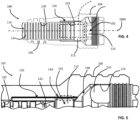
Fig. 4 is a cross-section view along the elongate axis of coaxial jumper cable which is disposed in combination with the weather protection boot according to the embodiment shown inFigs. 1-3 . -
Fig. 5 is an enlarged sectional view of the weather protection boot showing the structure and function of the elongate slots relative to the body of the coaxial cable assembly. - A weather protecting boot is described for providing water, wind, ice sand and foreign object damage to coaxial cable connections. As described in the Background of the Invention, such weather protection boots are typically disposed over coaxial cables connectors used outdoors, i.e., typically for connections made on cellular communications towers, i.e., between jumper cables and telecommunications antennas.
- A typical jumper cable employs a coaxial cable having a cable connector disposed at each end. A coaxial cable typically comprises: (a) a conductive, central wire, tube, strand or inner conductor; (b) a cylindrical or tubular dielectric, or insulator that receives and surrounds the inner conductor; (c) a conductive tube or outer conductor that receives and surrounds the dielectric or insulator; and (d) a sheath, sleeve or outer jacket that receives and surrounds the outer conductor. The outer conductor may be corrugated, i.e., defining a plurality of peaks and valleys, to facilitate flexing or bending of the cable relative to an elongate axis.
- The connectors may be any of a standard variety including F-type, hyperboloid, RF, Fiber Optic connectors. A typical coaxial cable connector may include: (a) a connector housing or connector body; (b) a nut or coupler that receives, and rotates relative to, the connector body; (c) a post interposing the dielectric insulator and the outer conductor to provide an electrical ground path from the outer conductor to an interface port or connector and (d) a compressor or fastener disposed over the outer jacket, in the region of the post, to mechanically and electrically couple the connector to the cable.
- In one embodiment of the invention, a weather protecting/proofing boot such as the
cover 100 illustrated inFigs. 1-5 , is configured to enclose part or all of thecable connector 102. The weather protecting/proofingprotective housing 100 functions to provide an environmental seal to prevent the infiltration of environmental elements, such as rain, snow, ice, salt, dust, debris and air pressure, into theconnector 104 and an interface port (not shown). The terms "weather-proofing" and "weather-protecting" are used interchangeably herein inasmuch as the assembly provides either or both of a geometric configuration which either weather proofs or provides protection against the elements. - The weather protecting/proofing
housing 100 may be constructed from a material having a suitable foldable, stretchable or flexible construction or characteristic. Such flexible materials may include synthetic rubber, natural rubber or a silicon-based material. InFigs. 1-3 , theprotective housing 100 may having a plurality of different inner diameters D1, D2, D3 and a plurality of annular rings orgrooves protective housing 100. More specifically, the protective housing defines at least three (3) diameters D1, D2, D3 corresponding to a different portion of the connector or the coaxial cable. For example, diameters D1 and D2 correspond to the coupler and body portions, 110, and 112, respectively, of thecable connector 102. Diameter D3 corresponds to theouter surface 114 of thecoaxial cable 116. As such, the inner surfaces of theprotective cover 100 conforms to, and physically engages,outer surfaces connector 102 and the outer periphery of thecable 116 to establish a tight environmental seal. - In the described embodiment, the largest diameter D1 is defined by the first inner mold line (IML)
surface 118 which corresponds to and engages thecoupler 110 of theconnector 102. The smallest diameter D3 is defined by asecond IML surface 120 which corresponds and engages to theoutermost surface 114 of thecoaxial cable 116. Finally, an intermediate diameter D2 is defined by anintermediate IML surface 122 which corresponds and engages thebody 112 of theconnector 102. Accordingly, theprotective housing 100 engages at least two peripheral surfaces of theconnector 102, i.e., thecoupler 110 and thebody 112, in addition to the outerperipheral surface 114 of thecoaxial cable 116. - The outer
peripheral surface 114 of thecoaxial cable 116 may be the compliant outer elastomer jacket (not shown) of thecoaxial cable 102. In other embodiments, such as the embodiment illustrated inFigs. 4 and 5 , the outerperipheral surface 114 is defined by a corrugated polyvinyl-chloride (PVC) cover disposed over the compliant outer elastomeric jacket (not shown) of thecoaxial cable 102. As part of this embodiment, the inventors discovered that certain birds, indigenous to certain parts of the globe, have a natural (or unnatural) desire to gnaw on and ingest the rubber or elastomeric materials used to fabricate the outer compliant jacket of thecoaxial cable 102. For example, parrots, indigenous to the country of Australia, appear to have an affinity for gnawing on, and ingesting, elastomeric materials which tend to damage and expose the outer conductor of thecable 102. These same inventors learned that other materials appeared to be less attractive to the elastomer-ingesting parrots of the Australian outback. That is, the inventors discovered that the birds did not have the same affinity for polyvinyl-chloride (PVC) materials. Consequently, the inventors covered the compliant elastomeric outer jacket with a peripheral layer 114 (seeFig. 4 ) of corrugated PVC. Consequently, the smallest diameter D3 of the innermold line surface 120 corresponds to and engages a bird-protectingcorrugated PVC layer 114 of thecoaxial cable 102. It will be appreciated that theprotective housing 100 may also comprise an outer layer of Polyvinyl-Chloride (PVC) material to prevent birds form ingesting theprotective housing 100. The PVC portion of thehousing 100 may be integrally molded with the boot, or alternatively, include a conically-shaped cover disposed over theprotective housing 100. - While each of these inner mold line surfaces establish a tight environmental seal, as discussed in the Background of the invention, certain advantages are achievable by using a housing which protects multiple configurations of the
coaxial cable connector 102. As such, an operator no longer needs to carry a large inventory of housings, i.e., each having slightly different IML dimensions. In contrast, the operator only needs to carry a single multi-use protective housing capable of protecting a variety of connectors and housing assemblies. Consequently, there is a significant savings in the cost of just-in-time inventory. - To achieve these objectives, the
protective housing 100 is configured with multipleelongate slots 150. Each of theslots 150 is disposed along at least one of the inner mold line (IML) surfaces 118, 120, 122 and is in fluid communication with one of the adjacent inner mold line (IML) surfaces 118, 120, 122. In the described embodiment, the plurality ofslots 150 is disposed along theintermediate IML surface 118 and is in fluid communication with the first IML surface of thecoaxial cable connector 102. Hence, theintermediate IML surface 122 corresponds to thebody portion 112 of theconnector 102 and thefirst IML surface 118 corresponds to thecoupler 110 of theconnector 102. - In
Figs. 2 ,4 and 5 , a total of six (6)elongate slots 150 are disposed about the inner mold line surface 122 (best seen inFig. 5 ) corresponding to thebody 112 of thecoaxial cable connector 102. Furthermore, theelongate slots 150 of the intermediatemold line surface 122, or intermediate diameter D2, are each in fluid communication with the adjacent firstmold line surface 118 which corresponds to diameter D1. It will be appreciated that, in order to be in fluid communication with the firstmold line surface 118, theelongate slots 150 must first be in fluid communication with atransition region 130 disposed between the first and intermediate IML surfaces 118, 122. - According to the invention, the
elongate slots 150 are equiangularly-spaced and define an arc, or angle β, of about sixty degrees (60°) from the centerline of oneslot 150 to the centerline of anadjacent slot 150. Furthermore, the width dimension W of eachelongate slot 150 defines an arc, or angle α of about 30 degrees (30°.) Consequently, the area of frictional engagement between each of the six (6)elongate slots 150 is equal to the expression α∗ D2 * W which is about 1/2 of the total area of engagement. - In
Figs. 3 and4 , theelongate slots 150 are substantially parallel to thelongitudinal axis 100A of theprotective housing 100 and are between about 0.63 to 1.89 cm (one-quarter inch (1/4") inch to about three-quarter inches (3/4")) in length dimension.Figure 5 shows an area ofclearance 140 between eachelongate slot 150 to: (i) facilitate assembly, i.e., prevent the build-up of air; and (ii) ease disassembly, i.e., by preventing suction from resisting the separation of thehousing 100 from theconnector 150. According to the invention, the minimum length LP1 of eachelongate slot 150, as a function of the total length LT of theintermediate IML surface 118, is at least twenty-five 25%. The maximum length LP2 of eachelongate slot 150 as a function of the total length LT is at least seventy-five 75%. - Additional embodiments include any one of the embodiments described above, where one or more of its components, functionalities or structures is interchanged with, replaced by or augmented by one or more of the components, functionalities or structures of a different embodiment described above.
Claims (4)
- Protective housing for a telecommunications interface and/or a jumper cable comprising:a boot (100) comprised of an elastomeric material and having a central bore receiving a prepared end of a coaxial cable connector (102), the boot (100) comprising at least three portions corresponding to peripheral surfaces of either a coaxial cable (116) or the connector (102);a first portion having a first inner mold line (IML) surface (118) corresponding to a first connector surface at one end;a second portion having a second IML surface (120) corresponding to a coaxial cable surface at another end;a third portion having an intermediate IML surface (122) corresponding to a second connector surface; and characterized by:six equiangularly-spaced elongate slots (150) disposed parallel to a longitudinal axis defined by the boot (100) along at least one of the IML surfaces (122) and in fluid communication with one of the adjacent IML surfaces (118),wherein the elongate slots (150) provide a fluid passageway to prevent the build-up of air pressure to facilitate assembly and disassembly of the boot (100) from the connector (102),wherein a length of each of the elongated slots (150) is between twenty-five percent (25%) of the total intermediate IML surface (122) and seventy-five percent (75%) of the total intermediate IML surface (122),wherein the elongate slots (150) eliminate about one-half (1/2) of the elastomeric material in frictional engagement with the connector (102), andwherein a width of each of the elongated slots (150) defines an arc of 30 degrees.
- The protective housing of claim 1, further comprising a transition region (130) between the intermediate and the first IML surfaces (118, 122) and wherein each of the elongate slots (150) is in fluid communication with the transition region (130).
- The protective housing of claim 1, characterized in that the elongate slots (150) are equiangularly-spaced about an inner circumference of the first IML surface (118).
- The protective housing of claim 1, characterized in that the at least one of the first and second IML surfaces (118, 120) comprises a plurality of annular engagement rings to facilitate frictional engagement of the first and second IML surfaces (118, 120).
Applications Claiming Priority (2)
| Application Number | Priority Date | Filing Date | Title |
|---|---|---|---|
| US201762550986P | 2017-08-28 | 2017-08-28 | |
| PCT/US2018/048308 WO2019046277A1 (en) | 2017-08-28 | 2018-08-28 | Weather protecting (wp) housing for coaxial cable connectors |
Publications (3)
| Publication Number | Publication Date |
|---|---|
| EP3676914A1 EP3676914A1 (en) | 2020-07-08 |
| EP3676914A4 EP3676914A4 (en) | 2021-04-28 |
| EP3676914B1 true EP3676914B1 (en) | 2023-08-16 |
Family
ID=65527913
Family Applications (1)
| Application Number | Title | Priority Date | Filing Date |
|---|---|---|---|
| EP18852122.3A Active EP3676914B1 (en) | 2017-08-28 | 2018-08-28 | Weather protecting (wp) housing for coaxial cable connectors |
Country Status (5)
| Country | Link |
|---|---|
| US (2) | US10811814B2 (en) |
| EP (1) | EP3676914B1 (en) |
| CN (1) | CN111344912B (en) |
| AU (1) | AU2018326480B2 (en) |
| WO (1) | WO2019046277A1 (en) |
Families Citing this family (5)
| Publication number | Priority date | Publication date | Assignee | Title |
|---|---|---|---|---|
| PT3675853T (en) | 2017-08-28 | 2022-11-28 | Amicus Therapeutics Inc | Methods of enhancing and/or stabilizing cardiac function in patients with fabry disease |
| US11387612B2 (en) | 2020-02-26 | 2022-07-12 | Dish Wireless L.L.C. | Cellular base station radio to antenna connection system |
| US11081781B1 (en) | 2020-02-26 | 2021-08-03 | Dish Wireless L.L.C. | Cellular base station keyed cable connectors |
| CN113594794B (en) * | 2021-07-28 | 2023-08-18 | 西安苏试广博环境可靠性实验室有限公司 | Grounding device of electromagnetic compatible circuit convenient to operate |
| CN119419497B (en) * | 2025-01-08 | 2025-03-28 | 深圳市天迈通信技术有限公司 | A high stability antenna phase-stabilizing cable |
Family Cites Families (12)
| Publication number | Priority date | Publication date | Assignee | Title |
|---|---|---|---|---|
| US3120987A (en) * | 1961-02-21 | 1964-02-11 | Hubbell Inc Harvey | Electrical cord connector having an improved protective covering |
| US3905672A (en) * | 1974-05-28 | 1975-09-16 | Itt | Sealed electrical connector |
| US4702710A (en) * | 1986-06-20 | 1987-10-27 | Georgia Tech Research Corporation | Waterproof seal assembly for electrical connector |
| GB2274025A (en) * | 1993-01-05 | 1994-07-06 | Cheng Sheng Hsu | Protecting sleeve for coaxial connector |
| CA2140058C (en) * | 1994-01-21 | 2005-04-12 | Cosmo Castaldo | Electrical joint environmental seal and method |
| US6007378A (en) * | 1997-05-02 | 1999-12-28 | Qualcomm Incorporated | Locking boot system |
| US6331123B1 (en) | 2000-11-20 | 2001-12-18 | Thomas & Betts International, Inc. | Connector for hard-line coaxial cable |
| US7479033B1 (en) * | 2007-07-23 | 2009-01-20 | Tyco Electronics Corporation | High performance coaxial connector |
| CN201616551U (en) * | 2010-03-10 | 2010-10-27 | 帛江科技股份有限公司 | Terminal protection device |
| CN202004217U (en) * | 2010-11-05 | 2011-10-05 | 富士康(昆山)电脑接插件有限公司 | Electric coupler assembly |
| US9028276B2 (en) * | 2011-12-06 | 2015-05-12 | Pct International, Inc. | Coaxial cable continuity device |
| US9147963B2 (en) * | 2012-11-29 | 2015-09-29 | Corning Gilbert Inc. | Hardline coaxial connector with a locking ferrule |
-
2018
- 2018-08-28 US US16/640,174 patent/US10811814B2/en active Active
- 2018-08-28 EP EP18852122.3A patent/EP3676914B1/en active Active
- 2018-08-28 WO PCT/US2018/048308 patent/WO2019046277A1/en not_active Ceased
- 2018-08-28 CN CN201880056573.2A patent/CN111344912B/en active Active
- 2018-08-28 AU AU2018326480A patent/AU2018326480B2/en active Active
-
2020
- 2020-10-15 US US17/071,741 patent/US11056824B2/en active Active
Also Published As
| Publication number | Publication date |
|---|---|
| US20200212621A1 (en) | 2020-07-02 |
| CN111344912B (en) | 2021-12-28 |
| EP3676914A1 (en) | 2020-07-08 |
| CN111344912A (en) | 2020-06-26 |
| US11056824B2 (en) | 2021-07-06 |
| WO2019046277A1 (en) | 2019-03-07 |
| AU2018326480A1 (en) | 2020-02-27 |
| US20210028575A1 (en) | 2021-01-28 |
| AU2018326480B2 (en) | 2023-06-29 |
| US10811814B2 (en) | 2020-10-20 |
| EP3676914A4 (en) | 2021-04-28 |
Similar Documents
| Publication | Publication Date | Title |
|---|---|---|
| US11056824B2 (en) | Weather protecting (WP) housing for coaxial cable connectors | |
| US7021965B1 (en) | Coaxial cable compression connector | |
| US7255598B2 (en) | Coaxial cable compression connector | |
| US8398421B2 (en) | Connector having a dielectric seal and method of use thereof | |
| US10186790B2 (en) | Connector producing a biasing force | |
| CA2240724C (en) | Coaxial cable connector | |
| US7029304B2 (en) | Compression connector with integral coupler | |
| US10637186B2 (en) | Hybrid feed-through connector for coaxial cables | |
| US20140087574A1 (en) | Connector having a nut-body continuity element and method of use thereof | |
| US9819170B2 (en) | Seal assembly/adaptor for an interface port | |
| US20220140521A1 (en) | Radio frequency (rf) connector having integrated weather protection system (wps) | |
| AU2018285692B2 (en) | Weather protecting (WP) boot for coaxial cable connectors | |
| CA2650516A1 (en) | Integrated outdoor termination for a high voltage cable |
Legal Events
| Date | Code | Title | Description |
|---|---|---|---|
| STAA | Information on the status of an ep patent application or granted ep patent |
Free format text: STATUS: THE INTERNATIONAL PUBLICATION HAS BEEN MADE |
|
| PUAI | Public reference made under article 153(3) epc to a published international application that has entered the european phase |
Free format text: ORIGINAL CODE: 0009012 |
|
| STAA | Information on the status of an ep patent application or granted ep patent |
Free format text: STATUS: REQUEST FOR EXAMINATION WAS MADE |
|
| 17P | Request for examination filed |
Effective date: 20200318 |
|
| AK | Designated contracting states |
Kind code of ref document: A1 Designated state(s): AL AT BE BG CH CY CZ DE DK EE ES FI FR GB GR HR HU IE IS IT LI LT LU LV MC MK MT NL NO PL PT RO RS SE SI SK SM TR |
|
| AX | Request for extension of the european patent |
Extension state: BA ME |
|
| DAV | Request for validation of the european patent (deleted) | ||
| DAX | Request for extension of the european patent (deleted) | ||
| A4 | Supplementary search report drawn up and despatched |
Effective date: 20210329 |
|
| RIC1 | Information provided on ipc code assigned before grant |
Ipc: H01R 13/52 20060101AFI20210323BHEP Ipc: H01R 24/38 20110101ALI20210323BHEP |
|
| GRAP | Despatch of communication of intention to grant a patent |
Free format text: ORIGINAL CODE: EPIDOSNIGR1 |
|
| STAA | Information on the status of an ep patent application or granted ep patent |
Free format text: STATUS: GRANT OF PATENT IS INTENDED |
|
| INTG | Intention to grant announced |
Effective date: 20230310 |
|
| GRAS | Grant fee paid |
Free format text: ORIGINAL CODE: EPIDOSNIGR3 |
|
| P01 | Opt-out of the competence of the unified patent court (upc) registered |
Effective date: 20230601 |
|
| GRAA | (expected) grant |
Free format text: ORIGINAL CODE: 0009210 |
|
| STAA | Information on the status of an ep patent application or granted ep patent |
Free format text: STATUS: THE PATENT HAS BEEN GRANTED |
|
| AK | Designated contracting states |
Kind code of ref document: B1 Designated state(s): AL AT BE BG CH CY CZ DE DK EE ES FI FR GB GR HR HU IE IS IT LI LT LU LV MC MK MT NL NO PL PT RO RS SE SI SK SM TR |
|
| REG | Reference to a national code |
Ref country code: CH Ref legal event code: EP |
|
| REG | Reference to a national code |
Ref country code: DE Ref legal event code: R096 Ref document number: 602018055643 Country of ref document: DE |
|
| REG | Reference to a national code |
Ref country code: IE Ref legal event code: FG4D |
|
| REG | Reference to a national code |
Ref country code: LT Ref legal event code: MG9D |
|
| REG | Reference to a national code |
Ref country code: NL Ref legal event code: MP Effective date: 20230816 |
|
| REG | Reference to a national code |
Ref country code: AT Ref legal event code: MK05 Ref document number: 1600996 Country of ref document: AT Kind code of ref document: T Effective date: 20230816 |
|
| PG25 | Lapsed in a contracting state [announced via postgrant information from national office to epo] |
Ref country code: GR Free format text: LAPSE BECAUSE OF FAILURE TO SUBMIT A TRANSLATION OF THE DESCRIPTION OR TO PAY THE FEE WITHIN THE PRESCRIBED TIME-LIMIT Effective date: 20231117 |
|
| PG25 | Lapsed in a contracting state [announced via postgrant information from national office to epo] |
Ref country code: IS Free format text: LAPSE BECAUSE OF FAILURE TO SUBMIT A TRANSLATION OF THE DESCRIPTION OR TO PAY THE FEE WITHIN THE PRESCRIBED TIME-LIMIT Effective date: 20231216 |
|
| PG25 | Lapsed in a contracting state [announced via postgrant information from national office to epo] |
Ref country code: SE Free format text: LAPSE BECAUSE OF FAILURE TO SUBMIT A TRANSLATION OF THE DESCRIPTION OR TO PAY THE FEE WITHIN THE PRESCRIBED TIME-LIMIT Effective date: 20230816 Ref country code: RS Free format text: LAPSE BECAUSE OF FAILURE TO SUBMIT A TRANSLATION OF THE DESCRIPTION OR TO PAY THE FEE WITHIN THE PRESCRIBED TIME-LIMIT Effective date: 20230816 Ref country code: PT Free format text: LAPSE BECAUSE OF FAILURE TO SUBMIT A TRANSLATION OF THE DESCRIPTION OR TO PAY THE FEE WITHIN THE PRESCRIBED TIME-LIMIT Effective date: 20231218 Ref country code: NO Free format text: LAPSE BECAUSE OF FAILURE TO SUBMIT A TRANSLATION OF THE DESCRIPTION OR TO PAY THE FEE WITHIN THE PRESCRIBED TIME-LIMIT Effective date: 20231116 Ref country code: NL Free format text: LAPSE BECAUSE OF FAILURE TO SUBMIT A TRANSLATION OF THE DESCRIPTION OR TO PAY THE FEE WITHIN THE PRESCRIBED TIME-LIMIT Effective date: 20230816 Ref country code: LV Free format text: LAPSE BECAUSE OF FAILURE TO SUBMIT A TRANSLATION OF THE DESCRIPTION OR TO PAY THE FEE WITHIN THE PRESCRIBED TIME-LIMIT Effective date: 20230816 Ref country code: LT Free format text: LAPSE BECAUSE OF FAILURE TO SUBMIT A TRANSLATION OF THE DESCRIPTION OR TO PAY THE FEE WITHIN THE PRESCRIBED TIME-LIMIT Effective date: 20230816 Ref country code: IS Free format text: LAPSE BECAUSE OF FAILURE TO SUBMIT A TRANSLATION OF THE DESCRIPTION OR TO PAY THE FEE WITHIN THE PRESCRIBED TIME-LIMIT Effective date: 20231216 Ref country code: HR Free format text: LAPSE BECAUSE OF FAILURE TO SUBMIT A TRANSLATION OF THE DESCRIPTION OR TO PAY THE FEE WITHIN THE PRESCRIBED TIME-LIMIT Effective date: 20230816 Ref country code: GR Free format text: LAPSE BECAUSE OF FAILURE TO SUBMIT A TRANSLATION OF THE DESCRIPTION OR TO PAY THE FEE WITHIN THE PRESCRIBED TIME-LIMIT Effective date: 20231117 Ref country code: FI Free format text: LAPSE BECAUSE OF FAILURE TO SUBMIT A TRANSLATION OF THE DESCRIPTION OR TO PAY THE FEE WITHIN THE PRESCRIBED TIME-LIMIT Effective date: 20230816 Ref country code: AT Free format text: LAPSE BECAUSE OF FAILURE TO SUBMIT A TRANSLATION OF THE DESCRIPTION OR TO PAY THE FEE WITHIN THE PRESCRIBED TIME-LIMIT Effective date: 20230816 |
|
| PG25 | Lapsed in a contracting state [announced via postgrant information from national office to epo] |
Ref country code: PL Free format text: LAPSE BECAUSE OF FAILURE TO SUBMIT A TRANSLATION OF THE DESCRIPTION OR TO PAY THE FEE WITHIN THE PRESCRIBED TIME-LIMIT Effective date: 20230816 |
|
| REG | Reference to a national code |
Ref country code: CH Ref legal event code: PL |
|
| PG25 | Lapsed in a contracting state [announced via postgrant information from national office to epo] |
Ref country code: LU Free format text: LAPSE BECAUSE OF NON-PAYMENT OF DUE FEES Effective date: 20230828 |
|
| PG25 | Lapsed in a contracting state [announced via postgrant information from national office to epo] |
Ref country code: ES Free format text: LAPSE BECAUSE OF FAILURE TO SUBMIT A TRANSLATION OF THE DESCRIPTION OR TO PAY THE FEE WITHIN THE PRESCRIBED TIME-LIMIT Effective date: 20230816 |
|
| PG25 | Lapsed in a contracting state [announced via postgrant information from national office to epo] |
Ref country code: SM Free format text: LAPSE BECAUSE OF FAILURE TO SUBMIT A TRANSLATION OF THE DESCRIPTION OR TO PAY THE FEE WITHIN THE PRESCRIBED TIME-LIMIT Effective date: 20230816 Ref country code: RO Free format text: LAPSE BECAUSE OF FAILURE TO SUBMIT A TRANSLATION OF THE DESCRIPTION OR TO PAY THE FEE WITHIN THE PRESCRIBED TIME-LIMIT Effective date: 20230816 Ref country code: LU Free format text: LAPSE BECAUSE OF NON-PAYMENT OF DUE FEES Effective date: 20230828 Ref country code: ES Free format text: LAPSE BECAUSE OF FAILURE TO SUBMIT A TRANSLATION OF THE DESCRIPTION OR TO PAY THE FEE WITHIN THE PRESCRIBED TIME-LIMIT Effective date: 20230816 Ref country code: EE Free format text: LAPSE BECAUSE OF FAILURE TO SUBMIT A TRANSLATION OF THE DESCRIPTION OR TO PAY THE FEE WITHIN THE PRESCRIBED TIME-LIMIT Effective date: 20230816 Ref country code: DK Free format text: LAPSE BECAUSE OF FAILURE TO SUBMIT A TRANSLATION OF THE DESCRIPTION OR TO PAY THE FEE WITHIN THE PRESCRIBED TIME-LIMIT Effective date: 20230816 Ref country code: CZ Free format text: LAPSE BECAUSE OF FAILURE TO SUBMIT A TRANSLATION OF THE DESCRIPTION OR TO PAY THE FEE WITHIN THE PRESCRIBED TIME-LIMIT Effective date: 20230816 Ref country code: SK Free format text: LAPSE BECAUSE OF FAILURE TO SUBMIT A TRANSLATION OF THE DESCRIPTION OR TO PAY THE FEE WITHIN THE PRESCRIBED TIME-LIMIT Effective date: 20230816 Ref country code: CH Free format text: LAPSE BECAUSE OF NON-PAYMENT OF DUE FEES Effective date: 20230831 |
|
| REG | Reference to a national code |
Ref country code: BE Ref legal event code: MM Effective date: 20230831 |
|
| REG | Reference to a national code |
Ref country code: DE Ref legal event code: R097 Ref document number: 602018055643 Country of ref document: DE |
|
| REG | Reference to a national code |
Ref country code: IE Ref legal event code: MM4A |
|
| PG25 | Lapsed in a contracting state [announced via postgrant information from national office to epo] |
Ref country code: MC Free format text: LAPSE BECAUSE OF FAILURE TO SUBMIT A TRANSLATION OF THE DESCRIPTION OR TO PAY THE FEE WITHIN THE PRESCRIBED TIME-LIMIT Effective date: 20230816 |
|
| PLBE | No opposition filed within time limit |
Free format text: ORIGINAL CODE: 0009261 |
|
| STAA | Information on the status of an ep patent application or granted ep patent |
Free format text: STATUS: NO OPPOSITION FILED WITHIN TIME LIMIT |
|
| PG25 | Lapsed in a contracting state [announced via postgrant information from national office to epo] |
Ref country code: IE Free format text: LAPSE BECAUSE OF NON-PAYMENT OF DUE FEES Effective date: 20230828 |
|
| 26N | No opposition filed |
Effective date: 20240517 |
|
| GBPC | Gb: european patent ceased through non-payment of renewal fee |
Effective date: 20231116 |
|
| PG25 | Lapsed in a contracting state [announced via postgrant information from national office to epo] |
Ref country code: IT Free format text: LAPSE BECAUSE OF FAILURE TO SUBMIT A TRANSLATION OF THE DESCRIPTION OR TO PAY THE FEE WITHIN THE PRESCRIBED TIME-LIMIT Effective date: 20230816 Ref country code: IE Free format text: LAPSE BECAUSE OF NON-PAYMENT OF DUE FEES Effective date: 20230828 Ref country code: SI Free format text: LAPSE BECAUSE OF FAILURE TO SUBMIT A TRANSLATION OF THE DESCRIPTION OR TO PAY THE FEE WITHIN THE PRESCRIBED TIME-LIMIT Effective date: 20230816 |
|
| PG25 | Lapsed in a contracting state [announced via postgrant information from national office to epo] |
Ref country code: BE Free format text: LAPSE BECAUSE OF NON-PAYMENT OF DUE FEES Effective date: 20230831 |
|
| PG25 | Lapsed in a contracting state [announced via postgrant information from national office to epo] |
Ref country code: GB Free format text: LAPSE BECAUSE OF NON-PAYMENT OF DUE FEES Effective date: 20231116 |
|
| PG25 | Lapsed in a contracting state [announced via postgrant information from national office to epo] |
Ref country code: GB Free format text: LAPSE BECAUSE OF NON-PAYMENT OF DUE FEES Effective date: 20231116 |
|
| PG25 | Lapsed in a contracting state [announced via postgrant information from national office to epo] |
Ref country code: BG Free format text: LAPSE BECAUSE OF FAILURE TO SUBMIT A TRANSLATION OF THE DESCRIPTION OR TO PAY THE FEE WITHIN THE PRESCRIBED TIME-LIMIT Effective date: 20230816 |
|
| PG25 | Lapsed in a contracting state [announced via postgrant information from national office to epo] |
Ref country code: BG Free format text: LAPSE BECAUSE OF FAILURE TO SUBMIT A TRANSLATION OF THE DESCRIPTION OR TO PAY THE FEE WITHIN THE PRESCRIBED TIME-LIMIT Effective date: 20230816 |
|
| PG25 | Lapsed in a contracting state [announced via postgrant information from national office to epo] |
Ref country code: CY Free format text: LAPSE BECAUSE OF FAILURE TO SUBMIT A TRANSLATION OF THE DESCRIPTION OR TO PAY THE FEE WITHIN THE PRESCRIBED TIME-LIMIT; INVALID AB INITIO Effective date: 20180828 |
|
| PG25 | Lapsed in a contracting state [announced via postgrant information from national office to epo] |
Ref country code: HU Free format text: LAPSE BECAUSE OF FAILURE TO SUBMIT A TRANSLATION OF THE DESCRIPTION OR TO PAY THE FEE WITHIN THE PRESCRIBED TIME-LIMIT; INVALID AB INITIO Effective date: 20180828 |
|
| PGFP | Annual fee paid to national office [announced via postgrant information from national office to epo] |
Ref country code: DE Payment date: 20250702 Year of fee payment: 8 |
|
| PGFP | Annual fee paid to national office [announced via postgrant information from national office to epo] |
Ref country code: FR Payment date: 20250703 Year of fee payment: 8 |
|
| PG25 | Lapsed in a contracting state [announced via postgrant information from national office to epo] |
Ref country code: TR Free format text: LAPSE BECAUSE OF FAILURE TO SUBMIT A TRANSLATION OF THE DESCRIPTION OR TO PAY THE FEE WITHIN THE PRESCRIBED TIME-LIMIT Effective date: 20230816 |