EP3676687B1 - Wearable device and method therein - Google Patents
Wearable device and method therein Download PDFInfo
- Publication number
- EP3676687B1 EP3676687B1 EP17787911.1A EP17787911A EP3676687B1 EP 3676687 B1 EP3676687 B1 EP 3676687B1 EP 17787911 A EP17787911 A EP 17787911A EP 3676687 B1 EP3676687 B1 EP 3676687B1
- Authority
- EP
- European Patent Office
- Prior art keywords
- display
- processing circuitry
- wearable device
- slave unit
- master unit
- Prior art date
- Legal status (The legal status is an assumption and is not a legal conclusion. Google has not performed a legal analysis and makes no representation as to the accuracy of the status listed.)
- Active
Links
Images


Classifications
-
- G—PHYSICS
- G09—EDUCATION; CRYPTOGRAPHY; DISPLAY; ADVERTISING; SEALS
- G09G—ARRANGEMENTS OR CIRCUITS FOR CONTROL OF INDICATING DEVICES USING STATIC MEANS TO PRESENT VARIABLE INFORMATION
- G09G5/00—Control arrangements or circuits for visual indicators common to cathode-ray tube indicators and other visual indicators
- G09G5/12—Synchronisation between the display unit and other units, e.g. other display units, video-disc players
-
- A—HUMAN NECESSITIES
- A61—MEDICAL OR VETERINARY SCIENCE; HYGIENE
- A61B—DIAGNOSIS; SURGERY; IDENTIFICATION
- A61B90/00—Instruments, implements or accessories specially adapted for surgery or diagnosis and not covered by any of the groups A61B1/00 - A61B50/00, e.g. for luxation treatment or for protecting wound edges
- A61B90/36—Image-producing devices or illumination devices not otherwise provided for
-
- G—PHYSICS
- G02—OPTICS
- G02B—OPTICAL ELEMENTS, SYSTEMS OR APPARATUS
- G02B27/00—Optical systems or apparatus not provided for by any of the groups G02B1/00 - G02B26/00, G02B30/00
- G02B27/01—Head-up displays
- G02B27/017—Head mounted
-
- G—PHYSICS
- G06—COMPUTING OR CALCULATING; COUNTING
- G06F—ELECTRIC DIGITAL DATA PROCESSING
- G06F3/00—Input arrangements for transferring data to be processed into a form capable of being handled by the computer; Output arrangements for transferring data from processing unit to output unit, e.g. interface arrangements
- G06F3/01—Input arrangements or combined input and output arrangements for interaction between user and computer
- G06F3/011—Arrangements for interaction with the human body, e.g. for user immersion in virtual reality
-
- G—PHYSICS
- G06—COMPUTING OR CALCULATING; COUNTING
- G06F—ELECTRIC DIGITAL DATA PROCESSING
- G06F3/00—Input arrangements for transferring data to be processed into a form capable of being handled by the computer; Output arrangements for transferring data from processing unit to output unit, e.g. interface arrangements
- G06F3/01—Input arrangements or combined input and output arrangements for interaction between user and computer
- G06F3/011—Arrangements for interaction with the human body, e.g. for user immersion in virtual reality
- G06F3/012—Head tracking input arrangements
-
- G—PHYSICS
- G06—COMPUTING OR CALCULATING; COUNTING
- G06F—ELECTRIC DIGITAL DATA PROCESSING
- G06F3/00—Input arrangements for transferring data to be processed into a form capable of being handled by the computer; Output arrangements for transferring data from processing unit to output unit, e.g. interface arrangements
- G06F3/01—Input arrangements or combined input and output arrangements for interaction between user and computer
- G06F3/03—Arrangements for converting the position or the displacement of a member into a coded form
- G06F3/033—Pointing devices displaced or positioned by the user, e.g. mice, trackballs, pens or joysticks; Accessories therefor
- G06F3/0346—Pointing devices displaced or positioned by the user, e.g. mice, trackballs, pens or joysticks; Accessories therefor with detection of the device orientation or free movement in a three-dimensional [3D] space, e.g. 3D mice, 6-DOF [six degrees of freedom] pointers using gyroscopes, accelerometers or tilt-sensors
-
- G—PHYSICS
- G09—EDUCATION; CRYPTOGRAPHY; DISPLAY; ADVERTISING; SEALS
- G09G—ARRANGEMENTS OR CIRCUITS FOR CONTROL OF INDICATING DEVICES USING STATIC MEANS TO PRESENT VARIABLE INFORMATION
- G09G3/00—Control arrangements or circuits, of interest only in connection with visual indicators other than cathode-ray tubes
- G09G3/001—Control arrangements or circuits, of interest only in connection with visual indicators other than cathode-ray tubes using specific devices not provided for in groups G09G3/02 - G09G3/36, e.g. using an intermediate record carrier such as a film slide; Projection systems; Display of non-alphanumerical information, solely or in combination with alphanumerical information, e.g. digital display on projected diapositive as background
- G09G3/003—Control arrangements or circuits, of interest only in connection with visual indicators other than cathode-ray tubes using specific devices not provided for in groups G09G3/02 - G09G3/36, e.g. using an intermediate record carrier such as a film slide; Projection systems; Display of non-alphanumerical information, solely or in combination with alphanumerical information, e.g. digital display on projected diapositive as background to produce spatial visual effects
-
- G—PHYSICS
- G09—EDUCATION; CRYPTOGRAPHY; DISPLAY; ADVERTISING; SEALS
- G09G—ARRANGEMENTS OR CIRCUITS FOR CONTROL OF INDICATING DEVICES USING STATIC MEANS TO PRESENT VARIABLE INFORMATION
- G09G5/00—Control arrangements or circuits for visual indicators common to cathode-ray tube indicators and other visual indicators
- G09G5/14—Display of multiple viewports
-
- H—ELECTRICITY
- H04—ELECTRIC COMMUNICATION TECHNIQUE
- H04N—PICTORIAL COMMUNICATION, e.g. TELEVISION
- H04N13/00—Stereoscopic video systems; Multi-view video systems; Details thereof
- H04N13/30—Image reproducers
- H04N13/332—Displays for viewing with the aid of special glasses or head-mounted displays [HMD]
- H04N13/344—Displays for viewing with the aid of special glasses or head-mounted displays [HMD] with head-mounted left-right displays
-
- H—ELECTRICITY
- H04—ELECTRIC COMMUNICATION TECHNIQUE
- H04N—PICTORIAL COMMUNICATION, e.g. TELEVISION
- H04N13/00—Stereoscopic video systems; Multi-view video systems; Details thereof
- H04N13/30—Image reproducers
- H04N13/398—Synchronisation thereof; Control thereof
-
- A—HUMAN NECESSITIES
- A61—MEDICAL OR VETERINARY SCIENCE; HYGIENE
- A61B—DIAGNOSIS; SURGERY; IDENTIFICATION
- A61B17/00—Surgical instruments, devices or methods
- A61B2017/00681—Aspects not otherwise provided for
- A61B2017/00734—Aspects not otherwise provided for battery operated
-
- A—HUMAN NECESSITIES
- A61—MEDICAL OR VETERINARY SCIENCE; HYGIENE
- A61B—DIAGNOSIS; SURGERY; IDENTIFICATION
- A61B34/00—Computer-aided surgery; Manipulators or robots specially adapted for use in surgery
- A61B34/20—Surgical navigation systems; Devices for tracking or guiding surgical instruments, e.g. for frameless stereotaxis
- A61B2034/2046—Tracking techniques
- A61B2034/2048—Tracking techniques using an accelerometer or inertia sensor
-
- A—HUMAN NECESSITIES
- A61—MEDICAL OR VETERINARY SCIENCE; HYGIENE
- A61B—DIAGNOSIS; SURGERY; IDENTIFICATION
- A61B34/00—Computer-aided surgery; Manipulators or robots specially adapted for use in surgery
- A61B34/20—Surgical navigation systems; Devices for tracking or guiding surgical instruments, e.g. for frameless stereotaxis
- A61B2034/2046—Tracking techniques
- A61B2034/2051—Electromagnetic tracking systems
-
- A—HUMAN NECESSITIES
- A61—MEDICAL OR VETERINARY SCIENCE; HYGIENE
- A61B—DIAGNOSIS; SURGERY; IDENTIFICATION
- A61B90/00—Instruments, implements or accessories specially adapted for surgery or diagnosis and not covered by any of the groups A61B1/00 - A61B50/00, e.g. for luxation treatment or for protecting wound edges
- A61B90/36—Image-producing devices or illumination devices not otherwise provided for
- A61B2090/364—Correlation of different images or relation of image positions in respect to the body
- A61B2090/365—Correlation of different images or relation of image positions in respect to the body augmented reality, i.e. correlating a live optical image with another image
-
- A—HUMAN NECESSITIES
- A61—MEDICAL OR VETERINARY SCIENCE; HYGIENE
- A61B—DIAGNOSIS; SURGERY; IDENTIFICATION
- A61B90/00—Instruments, implements or accessories specially adapted for surgery or diagnosis and not covered by any of the groups A61B1/00 - A61B50/00, e.g. for luxation treatment or for protecting wound edges
- A61B90/36—Image-producing devices or illumination devices not otherwise provided for
- A61B90/37—Surgical systems with images on a monitor during operation
- A61B2090/372—Details of monitor hardware
-
- A—HUMAN NECESSITIES
- A61—MEDICAL OR VETERINARY SCIENCE; HYGIENE
- A61B—DIAGNOSIS; SURGERY; IDENTIFICATION
- A61B90/00—Instruments, implements or accessories specially adapted for surgery or diagnosis and not covered by any of the groups A61B1/00 - A61B50/00, e.g. for luxation treatment or for protecting wound edges
- A61B90/50—Supports for surgical instruments, e.g. articulated arms
- A61B2090/502—Headgear, e.g. helmet, spectacles
-
- A—HUMAN NECESSITIES
- A61—MEDICAL OR VETERINARY SCIENCE; HYGIENE
- A61B—DIAGNOSIS; SURGERY; IDENTIFICATION
- A61B90/00—Instruments, implements or accessories specially adapted for surgery or diagnosis and not covered by any of the groups A61B1/00 - A61B50/00, e.g. for luxation treatment or for protecting wound edges
- A61B90/36—Image-producing devices or illumination devices not otherwise provided for
- A61B90/361—Image-producing devices, e.g. surgical cameras
-
- A—HUMAN NECESSITIES
- A61—MEDICAL OR VETERINARY SCIENCE; HYGIENE
- A61M—DEVICES FOR INTRODUCING MEDIA INTO, OR ONTO, THE BODY; DEVICES FOR TRANSDUCING BODY MEDIA OR FOR TAKING MEDIA FROM THE BODY; DEVICES FOR PRODUCING OR ENDING SLEEP OR STUPOR
- A61M2205/00—General characteristics of the apparatus
- A61M2205/50—General characteristics of the apparatus with microprocessors or computers
- A61M2205/502—User interfaces, e.g. screens or keyboards
- A61M2205/507—Head Mounted Displays [HMD]
-
- G—PHYSICS
- G09—EDUCATION; CRYPTOGRAPHY; DISPLAY; ADVERTISING; SEALS
- G09G—ARRANGEMENTS OR CIRCUITS FOR CONTROL OF INDICATING DEVICES USING STATIC MEANS TO PRESENT VARIABLE INFORMATION
- G09G2370/00—Aspects of data communication
- G09G2370/16—Use of wireless transmission of display information
Definitions
- Implementations described herein generally relate to a wearable device, and a method therein.
- Augmented Reality (AR) and Virtual Reality (VR) are rapidly emerging technologies.
- VR is a computer technology that uses a virtual reality headset to generate realistic images, sounds and other sensations that simulate a user's physical presence in a virtual or imaginary environment.
- a person using virtual reality equipment is able to "look around" the artificial world as he/ she moves his/ her head with the virtual reality equipment, and with high quality VR move about in it and possibly also interact with virtual features or items.
- the effect is commonly created by VR headsets comprising head-mounted goggles.
- VR is typically used for games and entertainment, but also for education, simulation and training purposes, etc.
- AR is a live direct or indirect view of a physical, real-world environment whose elements are "augmented” by computer-generated or extracted real-world sensory input such as sound, video, graphics, GPS data, sensor data, etc. It is related to a more general concept called computer-mediated reality, in which a view of reality is modified (possibly even diminished rather than augmented) by a computer. AR enhances a user's current perception of reality, whereas in contrast, VR replaces the real world with a simulated imaginary environment. Augmentation techniques are typically performed in real time and in semantic context with environmental elements, such as overlaying supplemental information like for example the remaining time (and/ or destination) to the next bus when the user is standing at a bus stop. Another example may be an AR device for construction workers which display information about the construction site.
- US 2016/163283 A1 discloses a virtual reality system including a host device and a head mounted display apparatus to be worn by a user.
- the head mounted display apparatus includes a first wireless module, a second wireless module, a multimedia module, a multi-sensing module, and a peripheral hub.
- the multimedia module receives multimedia content from the host device through the first wireless module.
- the multi-sensing module obtains sensing information regarding the head mounted display apparatus and the user.
- the peripheral hub receives communication data from the host device through the second wireless module, and provides the sensing information to the host device through the second wireless module.
- Document US 2003/0137528 A1 refers to a graphics system that is configured to synchronize a slave display channel to a master display channel and may include a master display timing generator configured to provide a frame event indication and a slave display timing generator.
- the slave display timing generator may be configured to receive the frame event indication and, in response to receiving the frame event indication during its active display period, the slave display timing generator may be configured to wait until its current active display period ends and then jump to its synchronization point.
- the slave display timing generator may be configured to jump to its synchronization point immediately or after the end of the current horizontal line, and any remaining display information in an interrupted frame may be displayed during the next active display period.
- Document US 2008/0266386 A1 discloses a system that comprises an HMD as a head mounted display device, and two image processing apparatuses.
- the user connects the image processing apparatuses respectively to a right-eye unit ("master") and a left-eye unit (“slave") of the HMD via a respective cable.
- the image processing apparatuses are connected to be able to communicate with each other via a network such as a LAN, Internet, or the like.
- the master image processing apparatus acquires data indicating the position and orientation of a right camera from an external sensor and transmits the data to the slave image processing unit.
- Each image processing unit generates an image of a virtual space seen from a viewpoint using a corresponding calculated position and orientation.
- a wearable device comprising a master unit and at least one slave unit.
- the master unit comprises a first display and a first processing circuitry
- the slave unit comprises a second display and a second processing circuitry.
- the wearable device aims at outputting information in the first and second displays.
- the first processing circuitry is configured to acquire at least one sensor signal from a sensor comprised in the master unit. Further, the first processing circuitry is configured to generate a synchronisation signal, based on the acquired sensor signal. In addition, the first processing circuitry is also configured to transmit the generated synchronisation signal to the slave unit. Also, the first processing circuitry is configured to render information to be outputted in the first display.
- the first processing circuitry is furthermore configured to transmit the rendered information to the first display for outputting the rendered information on the first display.
- the second processing circuitry is configured to receive the synchronisation signal from the master unit. Further, the second processing circuitry is configured to render information to be outputted in the second display, based on the received synchronisation signal. The second processing circuitry is also configured to transmit the rendered information to the second display, for outputting the rendered information on the second display.
- the outputted information comprises three dimensional information. Further, the three dimensional information to be rendered is comprised both in the master unit, and in the slave unit.
- the invention uses a low bandwidth connection between the master unit and the slave unit.
- low power consumption is required, leading to that a lighter battery, or batteries may be used, further reducing weight of the wearable device and also providing further design freedom.
- data transmission takes only a short time which enables low latency and reduces parallax problems between the images displayed on master and slave displays. Thereby, a better user experience is achieved.
- the first processing circuitry is further configured to transmit the generated synchronisation signal to the slave unit via the low bandwidth connection.
- the low bandwidth connection no high-bandwidth video link is physically routed between the modules with cables. Thereby a very lightweight and convenient wearable device is achieved. Also, the low bandwidth connection requires low energy consumption, which puts reduced requirements on the batteries. Smaller/ lighter batteries may then be used, leading to a yet lighter wearable device.
- the first processing circuitry may be further configured to transmit the generated synchronisation signal to the slave unit via a wireless communication interface.
- the first processing circuitry may be further configured to transmit the generated synchronisation signal to the slave unit via a wired communication interface.
- the first processing circuitry may be further configured to generate and transmit a synchronisation signal comprising a global time reference and sensor data, based on the acquired sensor signal.
- the synchronisation may be made in short time, leading to low latency with low bandwidth, which also leads to low power usage.
- the size of the power source may be reduced, leading to increased design freedom and less weight giving ergonomic advantages.
- the interval between battery charge may be extended, leading to enhanced user usefulness.
- the sensor comprised in the master unit may comprise any one of: a gyroscope, an accelerometer, and/ or a magnetometer.
- the wearable device may comprise one master unit and a plurality of slave units, wherein each slave unit may comprise a display and a processing circuitry.
- slave units e.g. stacked onto each other in an array of displays, a richer and more convincing three dimensional viewing experience is achieved.
- the first processing circuitry is configured to render the three dimensional information from a first angle
- the second processing circuitry is configured to render the three dimensional information from a second angle, distinct from the first angle, in order to achieve a stereo effect for a user, at the first and second displays.
- the master unit and the slave unit each comprises a separate memory.
- the wearable device comprises a pair of eyeglasses.
- the wearable device comprises a headwear, and the first display and the second display are arranged in association with the respective eye positions of the user.
- the rendered information comprises any of augmented reality, or virtual reality.
- a method in a wearable device is provided as defined in claim 11, wherein the wearable device comprises a master unit and at least one slave unit.
- the master unit comprises a first display and a first processing circuitry
- the slave unit comprises a second display and a second processing circuitry.
- the method aims at outputting information in the first display and the second display.
- the method comprises acquiring, by the first processing circuitry, at least one sensor signal from a sensor comprised in the master unit. Further, the method also comprises generating, by the first processing circuitry, a synchronisation signal, based on the acquired sensor signal.
- the method in addition comprises transmitting the generated synchronisation signal from the first processing circuitry to the second processing circuitry.
- the method furthermore comprises rendering information to be outputted in the first display at the master unit, and in the second display at the slave unit, based on the synchronisation signal.
- the method also comprises outputting the rendered information on the first display and the second display, respectively according to the transmitted synchronisation signal.
- a computer program comprising program code for performing a method, according to the second aspect, or any previously described implementation thereof, when the computer program runs on a computer.
- Embodiments of the invention described herein are defined as a wearable device, and a method therein, which may be put into practice in the embodiments described below. These embodiments may, however, be exemplified and realised in many different forms, within the scope of the appended claims, and are not to be limited to the examples set forth herein; rather, these illustrative examples of embodiments are provided so that this disclosure will be thorough and complete.
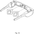
- a wearable device for outputting three dimensional (3D) information may comprise a pair of stereo AR/ VR glasses, as illustrated in Figure 1A .
- a schematic presentation of the stereo AR/ VR glasses of Figure 1A is presented in Figure 1B .
- a processor may be connected to various sensors such as e.g. a gyroscope, an accelerometer and a magnetometer. Further, the respective displays are connected to the common processor via multiple connections, e.g. 40-50 wires to each display. The processor may thereby render and synchronise the images to be outputted to the user.
- the conventional headset construction with multiple connections to each display puts severe limitations on the design of the wearable headset. The result is that the wearable device becomes aesthetically awkward, and also heavy. As most people who sometime has carried a pair of glasses of any arbitrary kind knows, also a small increase in weigh adds a substantial user discomfort, in particular when carried over a long period of time.
- Stereo AR/ VR glasses are typically so heavy that they present an ergonomic hazard to the user when worn for any substantial amount of time. They are typically also clumsy and limits the user's physical movements.
- FIG. 2 is a schematic illustration over a wearable device 200.
- the wearable device 200 may comprise a pair of stereo AR/ VR glasses, a helmet, or other similar headgear or headwear for outputting AR/ VR information to a user.
- the wearable device 200 may also be referred to as smart glasses, wearable computer glasses, smart lenses, smart binoculars, face-guard, smart goggles, sun glasses, diving masks, welding masks, etc.
- the wearable device 200 comprises a master unit 201 and a slave unit 202.
- the master unit 201 comprises a first display 210 and a first processing circuitry 230, while the slave unit 202 comprises a second display 220 and a second processing circuitry 240.
- the master unit 201 also comprises one or several sensors such as a gyroscope 250, an accelerometer 260 and/ or a magnetometer 270.
- the first display 210 and the second display 220 may comprise e.g. an Optical Head-Mounted Display (OHMD), which is a wearable device that has the capability of reflecting projected images as well as allowing the user to see through it, in an augmented reality implementation.
- OHMD Optical Head-Mounted Display
- the displays 210, 220 may comprise embedded wireless glasses with transparent Heads-Up Display (HUD) or AR overlay that has the capability of reflecting projected digital images as well as allowing the user to see through it, or even see better with it (by added correctional lenses and/ or sun shades etc.).
- HUD Heads-Up Display
- AR overlay that has the capability of reflecting projected digital images as well as allowing the user to see through it, or even see better with it (by added correctional lenses and/ or sun shades etc.).
- the outputted information of the first display 210 and the second display 220 may be projected on the respective display 210, 220 by a respective projector in the master device 201 and the slave device 202 in some embodiments.
- the first processing circuitry 230 and/ or the second processing circuitry 240 may, respectively, comprise one or more instances of a processing circuit, i.e. a Central Processing Unit (CPU), a processing unit, a processor, an Application Specific Integrated Circuit (ASIC), a microprocessor, or other processing logic that may interpret and execute instructions.
- a processing circuit i.e. a Central Processing Unit (CPU), a processing unit, a processor, an Application Specific Integrated Circuit (ASIC), a microprocessor, or other processing logic that may interpret and execute instructions.
- CPU Central Processing Unit
- ASIC Application Specific Integrated Circuit
- microprocessor or other processing logic that may interpret and execute instructions.
- processing circuitry may thus represent a plurality of processing circuits, such as, e.g., any, some or all of the ones enumerated above.
- the master unit 201 comprises a first memory 280 and the slave unit 202 comprises a second memory 290 which is distinct from the first memory 280.
- the first memory 280 and/ or the second memory 290 may comprise a respective physical device utilised to store data or programs, i.e., three dimensional information and sequences of instructions, on a temporary or permanent basis.
- the memories 280, 290 may comprise integrated circuits comprising silicon-based transistors. Further, the memories 280, 290 may be volatile or non-volatile.
- the respective first memory 280 and the second memory 290 both comprise common information concerning three dimensional information to be rendered in the first display 210 and the second display 220, respectively.
- the three dimensional information may comprise a VR universe in some embodiments when the wearable device 200 is dedicated for VR.
- the VR universe may for example comprise a room, a building or other structure within which the user may "move around" when using the wearable device 200.
- the three dimensional information may comprise AR information, which then is outputted in the displays 210, 220, overlaid to the real world information.
- the AR information may be associated with an object or a geographical position of the user's perceived real world wherein the user is situated.
- Some arbitrary examples of AR information may be graphics, text, documents, images, video, and/ or various sensor data such as e.g. time, temperature, etc., depending on application of the wearable device 200.
- the AR information may comprise blue prints, drawings, construction specifications etc., relevant for the particular construction site according to the instantaneous view and position of the user (or in fact, rather the wearable device 200).
- the three dimensional information comprising all the universe (AR or VR) which is to be rendered and outputted on the respective displays 210, 220 is, in accordance with the invention, comprised in both the respective first memory 280 (in the master unit 201) and the second memory 290 (in the slave unit 202).
- this information does not have to be transmitted from the master unit 201 to the slave unit 202, thereby enabling a low bandwidth connection between the master unit 201 and the slave unit 202.
- a power consumption lower than a threshold limit is required, leading to that a smaller/ lighter battery, or batteries may be used, further reducing weight of the wearable device and also providing further design freedom.
- data transmission takes only a short time which enables low latency and reduces parallax problems between the images displayed on master and slave displays. Thereby, a better user experience is achieved.
- the wearable device 200 thus comprises separate wireless processing and display modules 210, 220 for the respective (right/ left) eyes of the user, each rendering the view independently, however based on a synchronisation signal.
- the synchronisation signal serves the purpose of synchronising the outputted view on the first display 210 in the master unit 201 with the outputted view on the second display 220 in the slave unit 202, in time and optionally in space.
- the synchronisation signal may comprise a global time reference, for synchronising the first processing circuitry 230 with the second processing circuitry 240, in time.
- a sensor signal generated from one or several sensors in the master unit 201 is comprised, enabling the first processing circuitry 230 and the second processing circuitry 240 to determine which segment of the three dimensional world stored in the respective memories 280, 290.
- the sensor signal may comprise e.g. three orthogonal coordinates in a Cartesian coordinate system (for determining position of the user/ wearable device 200), a sensor signal for determining direction of the wearable device 200 and sensor signals for determining lateral and/ or horizontal tilting of the wearable device 200.
- the stored AR/ VR universe is limited, e.g.
- the height coordinate may be set to a constant value and thereby does not have to be part of the synchronisation signal (arbitrary non-limiting example only, the space position reference may be realised in many different ways leading to the same result, depending on implementation).
- the master unit 201 and the slave unit 202 synchronise their renderings so that they both render the same three dimensional information/ scene but slightly displaced, i.e. at a slightly different angle.
- a stereoscopic pair of images may be rendered by the respective processing circuitries 230, 240 and outputted by the respective displays 210, 220 to achieve a stereo effect as perceived by the user.
- the difference between the presentational angles of the master unit 201 and the slave unit 202 may be predetermined and constant in some embodiments, for creating the stereo effect of the rendered image.
- binocular vision results in two slightly different images projected to the retinas of the eyes.
- the differences are mainly in the relative horizontal position of objects in the two images. These positional differences are referred to as horizontal disparities or, more generally, binocular disparities.
- Disparities are processed in the visual cortex of the brain to yield depth perception. While binocular disparities are naturally present when viewing a real world three dimensional scene with two eyes, they can also be simulated by artificially outputting two different images separately to each eye of the user at the respective displays 210, 220, using a method called stereoscopy, which may be applied in some embodiments.
- stereoscopy which may be applied in some embodiments.
- the perception of depth in the outputted information/ image may also referred to as "stereoscopic depth".
- Low latency of the synchronisation signal between the master unit 201 and the slave unit 202 i.e. a latency below a predetermined or configurable threshold limit, prevents parallax problems or animations being out of sync.
- a low bandwidth link for the synchronisation will facilitate wireless synchronisation, and also lead to low power consumption.
- a wired or wireless high bandwidth link may be used.
- the connection between the first processing circuitry 230 of the master unit 201 and the second processing circuitry 240 of the slave unit 202 is made via a low bandwidth connection.
- power consumption may be kept low, resulting in that a smaller/ lighter power source, such as e.g. one or several batteries, may be utilised, in comparison with the conventional solution.
- a smaller/ lighter power source such as e.g. one or several batteries
- the total weight of the wearable device 200 may be reduced, leading to ergonomic advantages for the user.
- Low weight in combination with a design focusing on user ergonomics and/ or attractive design are important issues for enhancing the wearability on an everyday basis, or long term basis, of the wearable device 200.
- the master unit 201 and the slave unit 202 may each have their own respective battery, or set of batteries in some embodiments. In other embodiments, the master unit 201 and the slave unit 202 may share the same battery, or set of batteries.
- the low bandwidth connection may be a wireless connection in some embodiments, based on e.g. Bluetooth or other similar wireless communication protocol for short range transmission of wireless communication, e.g. Near Field Communication (NFC), RadioFrequency Identification (RFID), Z-wave, ZigBee, IPv6 over Low power Wireless Personal Area Networks (6LoWPAN), Wireless Highway Addressable Remote Transducer (HART) Protocol, Wireless Universal Serial Bus (USB), optical communication such as Infrared Data Association (IrDA), Low-Power Wide-Area Network (LPWAN) such as e.g. LoRa, etc.; to name but a few possible examples of wireless communications in some different embodiments.
- NFC Near Field Communication
- RFID RadioFrequency Identification
- Z-wave Z-wave
- ZigBee ZigBee
- IPv6 over Low power Wireless Personal Area Networks
- 6LoWPAN Wireless Highway Addressable Remote Transducer
- USB Wireless Universal Serial Bus
- optical communication such as Infrared Data Association (IrDA),
- An advantage with wireless communication between the first processing circuitry 230 of the master unit 201 and the second processing circuitry 240 of the slave unit 202, possibly via a respective wireless transceiver (or alternatively a wireless transmitter in the master unit 201 and a wireless receiver in the slave unit 202), is that no connecting cables are required, again saving some weight, but perhaps more important provide a greater freedom when designing the wearable device 200.
- the processing circuitries 230, 240 may, thanks to the wireless communication, for example be positioned several centimetres/ decimetres from the respective displays 210, 220; and may not necessarily be comprised in the same physical entity as the displays 210, 220 (although comprised in the same logical entity as illustrated in Figure 2 ).
- the processing circuitries 230, 240 may be comprised for example on the back or on top of the headwear, in some alternative embodiments, which may provide design advantages and/ or ergonomic advantages.
- the low bandwidth connection may alternatively be a wired connection in some embodiments using e.g. Inter-Integrated Circuit (I2C), or similar communication bus, such as e.g. ACCESS.bus (A.b), the Video Electronics Standards Association (VESA) Display Data Channel (DDC) interface, the System Management Bus (SMBus), Power Management Bus (PMBus), the Intelligent Platform Management Bus (IPMB), Two-Wire Interface (TWI), Two-Wire Serial Interface (TWSI), etc.
- the wired low bandwidth connection make use of 2-3 wires.
- the wired connection may have an advantage of providing a stable connection, not requiring a pairing and bonding procedure as may be the case with e.g. a Bluetooth connection.
- a wired connection may also be more secure than a wireless connection as, at least some wireless communication protocols such as e.g. Bluetooth may have a weakness for various security attacks, such as bluejacking, bluesnarfing, and/ or bluebugging.
- a synchronisation method is defined, enabling synchronisation of the image rendered (independently, however based on the synchronisation signal) on the first display 210 and on the second display 220, respectively.
- the device position and global time signal may be synchronised in some embodiments.
- the wearable device 200 comprises one master unit 201 and one, or several, slave units 202.
- the master unit 201 may comprise one or several sensors of the same or different types, such as e.g. the gyroscope 250, the accelerometer 260 and/ or the magnetometer 270 to place and rotate a camera in a 3D world.
- Information such as e.g. camera position, rotation and animation synchronisation signal may be sent to the slave unit 202, which uses this data to render the same scene at the second display 220, as rendered by the first processing circuitry 230 at the first display 210.
- the slave unit 202 may not comprise any own sensors; or at least not use any own sensor data.
- both the master unit 201 and the slave unit 202 may render the same scene, possibly outputted at different view angles to create a stereo view effect of the user, without experience any problems with e.g. sensor drift between the respective units 201, 202.
- the provided solution provides advantages regarding the wearable device mechanics and industrial design. Thanks to the increased design flexibility and reduced weight of the wearable device 200, a very lightweight and casual "smart glass" frames are provided, since no high-bandwidth video link is physically routed between the modules with cables. Further, low power consumption saves battery, leading to a yet lighter wearable device 200. Thereby, a convenient and comfortable wearable device 200 is achieved, which may be carried effortlessly by the user, continuously or for a long period of time.
- the head of the user is typically most sensible for excessive weight on the rather limited parts of the head that are supporting an eyewear, i.e. the root of the nose and the upper parts of the ears, why also a modest weight reduction will result in increased ergonomic user experience.
- the user will be able to carry the wearable device 200 for a longer period of time, with less discomfort; possibly the wearable device 200 may be used on an everyday basis in some embodiments.
- Figure 3 presents an example of a design of a wearable device 200, e.g. as previously schematically illustrated in Figure 2 and described above, comprising a pair of stereo AR/ VR glasses.
- Each of the master unit 201 and the slave unit 202 render a respective image, based on the common synchronisation signal, which may comprise a global time reference and sensor data achieved from sensors 250, 260, 270 of the master unit 201. Further, three dimensional information to be rendered is comprised both in the first memory 280 of the master unit 201, and in the second memory 290 of the slave unit 202, leading to that less information has to be transferred between the master unit 201 and the slave unit 202, which results in low latency.
- the purpose of the synchronisation signal is to synchronise the output of the respectively rendered information, made on the first display 210 and the second display 220.
- the wearable device 200 may comprise a plurality of slave units 202, each comprising one separate display and processing circuitry.
- the respective displays of these slave units 202 may be stacked onto each other in some embodiments.
- the stacked displays may be completely or partially transparent in some embodiments. Thereby, an enhanced three dimensional effect may be created.
- Figure 4 illustrates an example of a method for outputting information in the first and second displays 210, 220 of the wearable device 200.
- the master unit 201 may update at least any or some of its sensor values, such as e.g. any of an accelerometer value, a gyroscope value, an accelerometer value, a device position, a camera position, a position reference, a rotation and animation synchronisation reference, etc., in a first method step 401, and send them along with a global time reference signal to be received by the slave unit 202 in a subsequent step 402.
- the global time reference signal may be generated by a time measuring device of the master unit 201.
- the master unit 201 may render the image and output it on the first display 210, based on the sensor data in step 403A.
- the slave unit 202 When the slave unit 202 receives the synchronisation signal comprising the sensor data, it will also render the image on the second display 220 in step 403B, based on the synchronisation signal. Since the amount of data is very small, the data transmission of the data takes a very short time, which enables low latency and reduces parallax problems between the images displayed on the first display 210 of the master unit 201, and the second display 220 of the slave unit 202.
- Figure 5 is a block diagram illustrating encodings of data points in a synchronisation frame 500. If the all of the data points are encoded as 32-bit values, the size of one synchronisation frame can be encoded into 28 bytes, according to an implementation embodiment.
- Bandwidth ⁇ 100 bytes per frame may be achieved with practically any wireless technology.
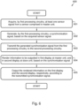
- Figure 6 is a flow chart illustrating an embodiment of a method 600 in a wearable device 200 comprising a master unit 201 and at least one slave unit 202.
- the master unit 201 comprises a first display 210 and a first processing circuitry 230
- the slave unit 202 comprises a second display 220 and a second processing circuitry 240, for outputting information in the first and second displays 210, 220.
- the information to be outputted comprises three dimensional information. Further, the outputted information may comprise augmented reality information, or mediated reality information in some embodiments. In other embodiments, the outputted information may comprise virtually reality information.
- the three dimensional information to be rendered is comprised both in the master unit 201, and in the slave unit 202, e.g. in order to achieve a stereo effect for a user, at the first and second displays 210, 220.
- the wearable device 200 may comprise a pair of eyeglasses in some embodiments. In other embodiments, the wearable device 200 may comprise a headwear, wherein the first display 210 and the second display 220 are arranged in association with the respective eye positions of the user.
- the method 600 comprises a number of steps 601-605.
- the wearable device 200 may in some embodiments periodically re-perform any, some or all of step 601-605, thereby enabling output of information in the first and second displays 210, 220 continuously.
- the method 600 may comprise the following steps: Step 601 comprises acquiring, by the first processing circuitry 230, at least one sensor signal from a sensor 250, 260, 270, comprised in the master unit 201.
- the sensor 250, 260, 270 may comprise e.g. a gyroscope 250, an accelerometer, a magnetometer 270, a camera, a solid state compass, a positioning device such as e.g. a Global Positioning System (GPS) device, etc.
- GPS Global Positioning System
- the sensor signal may comprise sensor data acquired from any one, several or all of the enumerated sensors 250, 260, 270 in different embodiments.
- the sensor signal makes it possible for the first processing circuitry 230, and later also the second processing circuitry 240 in the slave device 202, to position the device 200 correctly in the three dimensional world which is rendered and to be outputted on the respective displays 210, 220.
- the sensor data thereby comprises a spatial reference enabling determination of information to be outputted.
- Step 602 comprises generating, by the first processing circuitry 230, a synchronisation signal, based on the acquired 601 sensor signal.
- the generated synchronisation signal may comprise a global time reference and sensor data (spatial reference), based on the acquired 601 sensor signal.
- the purpose of the spatial reference is to enable the second processing circuitry 240 in the slave device 202 to determine which subset of the information stored in the second memory 290 to be outputted on the second display 220, synchronised in position with the information to be outputted on the first display 210 of the master device 201.
- the global time reference may be generated by a time measuring device comprised in the master device 201 in some embodiments.
- the synchronisation signal achieves, according to the invention, a synchronisation in time of the outputted information, outputted in the first display 210 and the second display 220, respectively, thereby providing an illusion of the user to move around in the three dimensional AR/ VR universe, as the wearable device 200 is displaced.
- the generated synchronisation signal may comprise device position and the global time reference. In some other embodiments, the generated synchronisation signal may comprise sensor/ camera position, rotation and animation synchronisation signal. In yet some embodiments, the synchronisation signal may comprise accelerometer and gyroscope values along with the global time reference.
- Step 603 comprises transmitting the generated 602 synchronisation signal from the first processing circuitry 230 of the master device 201 to the second processing circuitry 240 of the slave device 202.
- the transmission of the generated synchronisation signal to the slave unit 202 is made via a low bandwidth connection, i.e. a bandwidth lower than a predefined or configurable threshold limit of 2.1 Mbit/s.
- the low bandwidth connection may comprise a wireless communication interface; or alternatively a wired communication interface.
- Step 604 comprises rendering information to be outputted in the first display 210 at the master unit 201, and in the second display 220 at the slave unit 202, based on the received synchronisation signal.
- the rendered information by the respective displays 210, 220 is thereby synchronised in time and in space.
- the rendered information of the first processing circuitry 230 may comprise the three dimensional information from a first angle while the rendered information of the second processing circuitry 240 may comprise the three dimensional information from a second angle, distinct from the first angle, in order to achieve a stereo effect for a user, at the first and second displays 210, 220 in some embodiments.
- the rendered respective three dimensional information thus may form a stereoscopic pair of images, slightly displaced in relation to each other, for creating or enhancing the illusion of depth in the image as perceived by the user.
- the three dimensional information to be rendered is comprised both in a first memory 280 of the master unit 201, and in a second memory 290 of the slave unit 202, leading to that less information has to be transferred between the master unit 201 and the slave unit 202, which results in low latency.
- Step 605 comprises outputting the rendered 604 information on the first display 210 and the second display 220, respectively, according to the transmitted 603 synchronisation signal.
- At least a sub-set of the previously described method steps 601-605 to be performed in the wearable device 200 may be implemented through the first processing circuitry 230 in the master unit 201 and the second processing circuitry 240 in the slave unit 202, together with a computer program product for performing the functions of at least some of the method steps 601-605.
- a computer program product comprising instructions for performing the method steps 601-605 outputs information in the first and second displays 210, 220, when the computer program is loaded into the processing circuitries 230, 240.
- the computer program mentioned above may be provided for instance in the form of a data carrier carrying computer program code for performing at least some of the method steps 601-605 according to some embodiments when being loaded into the processing circuitries 230, 240.
- the data carrier may be, e.g., a hard disk, a CD ROM disc, a memory stick, an optical storage device, a magnetic storage device or any other appropriate medium such as a disk or tape that may hold machine readable data in a non-transitory manner.
- the computer program product may furthermore be provided as computer program code on a server and downloaded to the wearable device 200 remotely, e.g., over an Internet or an intranet connection.
- any, some or all method steps 601-605 may be iterated infinitely, for a limited period of time, or until a threshold limit is achieved.
- the term “and/ or” comprises any and all combinations of one or more of the associated listed items.
- the term “or” as used herein, is to be interpreted as a mathematical OR, i.e., as an inclusive disjunction; not as a mathematical exclusive OR (XOR), unless expressly stated otherwise.
- the singular forms “a”, “an” and “the” are to be interpreted as “at least one”, thus also possibly comprising a plurality of entities of the same kind, unless expressly stated otherwise.
Landscapes
- Engineering & Computer Science (AREA)
- Theoretical Computer Science (AREA)
- Physics & Mathematics (AREA)
- General Physics & Mathematics (AREA)
- General Engineering & Computer Science (AREA)
- Human Computer Interaction (AREA)
- Computer Hardware Design (AREA)
- Multimedia (AREA)
- Health & Medical Sciences (AREA)
- Signal Processing (AREA)
- Life Sciences & Earth Sciences (AREA)
- Surgery (AREA)
- Pathology (AREA)
- Animal Behavior & Ethology (AREA)
- Nuclear Medicine, Radiotherapy & Molecular Imaging (AREA)
- Biomedical Technology (AREA)
- Heart & Thoracic Surgery (AREA)
- Medical Informatics (AREA)
- Molecular Biology (AREA)
- Oral & Maxillofacial Surgery (AREA)
- General Health & Medical Sciences (AREA)
- Public Health (AREA)
- Veterinary Medicine (AREA)
- Optics & Photonics (AREA)
- Controls And Circuits For Display Device (AREA)
- User Interface Of Digital Computer (AREA)
Description
- Implementations described herein generally relate to a wearable device, and a method therein.
- Augmented Reality (AR) and Virtual Reality (VR) are rapidly emerging technologies.
- VR is a computer technology that uses a virtual reality headset to generate realistic images, sounds and other sensations that simulate a user's physical presence in a virtual or imaginary environment. A person using virtual reality equipment is able to "look around" the artificial world as he/ she moves his/ her head with the virtual reality equipment, and with high quality VR move about in it and possibly also interact with virtual features or items. The effect is commonly created by VR headsets comprising head-mounted goggles. VR is typically used for games and entertainment, but also for education, simulation and training purposes, etc.
- AR is a live direct or indirect view of a physical, real-world environment whose elements are "augmented" by computer-generated or extracted real-world sensory input such as sound, video, graphics, GPS data, sensor data, etc. It is related to a more general concept called computer-mediated reality, in which a view of reality is modified (possibly even diminished rather than augmented) by a computer. AR enhances a user's current perception of reality, whereas in contrast, VR replaces the real world with a simulated imaginary environment. Augmentation techniques are typically performed in real time and in semantic context with environmental elements, such as overlaying supplemental information like for example the remaining time (and/ or destination) to the next bus when the user is standing at a bus stop. Another example may be an AR device for construction workers which display information about the construction site.
-
US 2016/163283 A1 discloses a virtual reality system including a host device and a head mounted display apparatus to be worn by a user. The head mounted display apparatus includes a first wireless module, a second wireless module, a multimedia module, a multi-sensing module, and a peripheral hub. The multimedia module receives multimedia content from the host device through the first wireless module. The multi-sensing module obtains sensing information regarding the head mounted display apparatus and the user. The peripheral hub receives communication data from the host device through the second wireless module, and provides the sensing information to the host device through the second wireless module. - Document
US 2003/0137528 A1 refers to a graphics system that is configured to synchronize a slave display channel to a master display channel and may include a master display timing generator configured to provide a frame event indication and a slave display timing generator. The slave display timing generator may be configured to receive the frame event indication and, in response to receiving the frame event indication during its active display period, the slave display timing generator may be configured to wait until its current active display period ends and then jump to its synchronization point. Alternatively, the slave display timing generator may be configured to jump to its synchronization point immediately or after the end of the current horizontal line, and any remaining display information in an interrupted frame may be displayed during the next active display period. - Document
US 2008/0266386 A1 discloses a system that comprises an HMD as a head mounted display device, and two image processing apparatuses. The user connects the image processing apparatuses respectively to a right-eye unit ("master") and a left-eye unit ("slave") of the HMD via a respective cable. The image processing apparatuses are connected to be able to communicate with each other via a network such as a LAN, Internet, or the like. The master image processing apparatus acquires data indicating the position and orientation of a right camera from an external sensor and transmits the data to the slave image processing unit. Each image processing unit generates an image of a virtual space seen from a viewpoint using a corresponding calculated position and orientation. - It is therefore an objective to obviate at least some of the above mentioned disadvantages and to provide an improved wearable device for image output.
- This and other objectives are achieved by the features of the appended independent claims. Further implementation forms are apparent from the dependent claims, the description and the figures.
- According to a first aspect, a wearable device comprising a master unit and at least one slave unit is provided. The master unit comprises a first display and a first processing circuitry, and the slave unit comprises a second display and a second processing circuitry. The wearable device aims at outputting information in the first and second displays. The first processing circuitry is configured to acquire at least one sensor signal from a sensor comprised in the master unit. Further, the first processing circuitry is configured to generate a synchronisation signal, based on the acquired sensor signal. In addition, the first processing circuitry is also configured to transmit the generated synchronisation signal to the slave unit. Also, the first processing circuitry is configured to render information to be outputted in the first display. The first processing circuitry is furthermore configured to transmit the rendered information to the first display for outputting the rendered information on the first display. The second processing circuitry is configured to receive the synchronisation signal from the master unit. Further, the second processing circuitry is configured to render information to be outputted in the second display, based on the received synchronisation signal. The second processing circuitry is also configured to transmit the rendered information to the second display, for outputting the rendered information on the second display.
- By using a separate processing circuitry for each display and render information to be outputted independently by the respective processing circuitries, yet based on the synchronisation signal, it is avoided to use heavy multi-wire based connections between a single processing circuitry and the displays as according to conventional solutions. In the previously known solutions, these connections between the processing circuitry and the displays comprises approximately 40-50 copper wires for each connection, having a considerable weight and volume. Thereby, an extended design freedom is provided, enabling construction of a wearable device being comfortable, convenient and attractive to wear for a user.
- In the wearable device according to the first aspect, the outputted information comprises three dimensional information. Further, the three dimensional information to be rendered is comprised both in the master unit, and in the slave unit.
- By keeping the three dimensional information both in the master unit and in the slave unit, less information has to be exchanged between the respective processing circuitries, such that the invention uses a low bandwidth connection between the master unit and the slave unit. Thereby low power consumption is required, leading to that a lighter battery, or batteries may be used, further reducing weight of the wearable device and also providing further design freedom. Further, as only very little information has to be exchanged, data transmission takes only a short time which enables low latency and reduces parallax problems between the images displayed on master and slave displays. Thereby, a better user experience is achieved.
- The first processing circuitry is further configured to transmit the generated synchronisation signal to the slave unit via the low bandwidth connection.
- Thanks to the low bandwidth connection, no high-bandwidth video link is physically routed between the modules with cables. Thereby a very lightweight and convenient wearable device is achieved. Also, the low bandwidth connection requires low energy consumption, which puts reduced requirements on the batteries. Smaller/ lighter batteries may then be used, leading to a yet lighter wearable device.
- According to a possible implementation of the wearable device according to the first aspect, the first processing circuitry may be further configured to transmit the generated synchronisation signal to the slave unit via a wireless communication interface.
- Thanks to the wireless communication interface, further enhanced design freedom is achieved, as no physical cables has to be arranged between the master unit and the slave unit. Thereby, weight of the wearable device is also further reduced.
- According to a further possible implementation of the wearable device according to the first aspect, or any previously described implementation thereof, the first processing circuitry may be further configured to transmit the generated synchronisation signal to the slave unit via a wired communication interface.
- Thanks to the wired communication interface, a secure and reliable, yet rather lightweight communication interface between the master unit and the slave unit is provided.
- According to a further possible implementation of the wearable device according to the first aspect, or any previously described implementation thereof, the first processing circuitry may be further configured to generate and transmit a synchronisation signal comprising a global time reference and sensor data, based on the acquired sensor signal.
- By reducing the amount of data that has to be exchanged, the synchronisation may be made in short time, leading to low latency with low bandwidth, which also leads to low power usage. Thereby, the size of the power source may be reduced, leading to increased design freedom and less weight giving ergonomic advantages. Alternatively, the interval between battery charge may be extended, leading to enhanced user usefulness.
- According to a further possible implementation of the wearable device according to the first aspect, or any previously described implementation thereof, the sensor comprised in the master unit may comprise any one of: a gyroscope, an accelerometer, and/ or a magnetometer.
- By having only one set of sensors in the master unit and share the obtained sensor data with the slave unit, problems with sensor drift is avoided, in comparison with having distinct sets of sensors in the master unit and the slave unit.
- According to a further possible implementation of the wearable device according to the first aspect, or any previously described implementation thereof, the wearable device may comprise one master unit and a plurality of slave units, wherein each slave unit may comprise a display and a processing circuitry.
- By providing several slave units, e.g. stacked onto each other in an array of displays, a richer and more convincing three dimensional viewing experience is achieved.
- According to further possible implementation of the wearable device according to the first aspect, or any previously described implementation thereof, the first processing circuitry is configured to render the three dimensional information from a first angle, and the second processing circuitry is configured to render the three dimensional information from a second angle, distinct from the first angle, in order to achieve a stereo effect for a user, at the first and second displays.
- The distinct rendering of the respective images for the three dimensional scene at the processing circuitries, it is avoided to use a high-bandwidth video link for distributing information rendered at one common processing circuitry. Thereby weight is saved, and more flexibility is provided, when it comes to design of the wearable device.
- In the wearable device according to the first aspect, or any previously described implementation thereof, the master unit and the slave unit, each comprises a separate memory.
- Thanks to the separate memories of the master unit and the slave unit respectively, certain information comprising knowledge of the three dimensional information to be rendered is kept at the respective separate memories. Thereby, less information such as e.g. only position and location of the camera in the three dimensional space has to be communicated between the master unit and the slave unit. Thus low bandwidth content synchronisation is facilitated.
- According to a further possible implementation of the wearable device according to the first aspect, or any previously described implementation thereof, the wearable device comprises a pair of eyeglasses.
- Thereby a convenient embodiment of the wearable device is implemented.
- According to a further possible implementation of the wearable device according to the first aspect, or any previously described implementation thereof, the wearable device comprises a headwear, and the first display and the second display are arranged in association with the respective eye positions of the user.
- Thereby an alternative embodiment of the wearable device is implemented.
- According to a further possible implementation of the wearable device according to the first aspect, or any previously described implementation thereof, the rendered information comprises any of augmented reality, or virtual reality.
- Thereby, the rendered information is further specified.
- According to a second aspect, a method in a wearable device according to the first aspect, or any previously described implementation thereof, is is provided as defined in claim 11, wherein the wearable device comprises a master unit and at least one slave unit. The master unit comprises a first display and a first processing circuitry, and the slave unit comprises a second display and a second processing circuitry. The method aims at outputting information in the first display and the second display. The method comprises acquiring, by the first processing circuitry, at least one sensor signal from a sensor comprised in the master unit. Further, the method also comprises generating, by the first processing circuitry, a synchronisation signal, based on the acquired sensor signal. Also, the method in addition comprises transmitting the generated synchronisation signal from the first processing circuitry to the second processing circuitry. The method furthermore comprises rendering information to be outputted in the first display at the master unit, and in the second display at the slave unit, based on the synchronisation signal. The method also comprises outputting the rendered information on the first display and the second display, respectively according to the transmitted synchronisation signal.
- The advantages of the method according to the second aspect, and the implementations thereof, are the same as has been described for the wearable device of the first aspect, and the corresponding implementations thereof.
- According to a third aspect, a computer program is provided, comprising program code for performing a method, according to the second aspect, or any previously described implementation thereof, when the computer program runs on a computer.
- Other objects, advantages and novel features of the aspects of the invention will become apparent from the following detailed description.
- Various embodiments are described in more detail with reference to attached drawings, illustrating examples of embodiments of the invention in which:
- Figure 1A
- is a schematical illustration of a wearable device.
- Figure 1B
- is a block diagram illustrating a wearable device.
- Figure 2
- is a block diagram illustrating a wearable device according to an embodiment.
- Figure 3
- is a block diagram illustrating a wearable device according to an embodiment.
- Figure 4
- is a flow chart illustrating an embodiment of a method in a wearable device.
- Figure 5
- is a block diagram illustrating encodings of data points in a synchronisation frame.
- Figure 6
- is a flow chart illustrating a method in a wearable device according to an embodiment of the invention.
- Embodiments of the invention described herein are defined as a wearable device, and a method therein, which may be put into practice in the embodiments described below. These embodiments may, however, be exemplified and realised in many different forms, within the scope of the appended claims, and are not to be limited to the examples set forth herein; rather, these illustrative examples of embodiments are provided so that this disclosure will be thorough and complete.
- Still other objects and features may become apparent from the following detailed description, considered in conjunction with the accompanying drawings. It is to be understood, however, that the drawings are designed solely for purposes of illustration and not as a definition of the limits of the herein disclosed embodiments, for which reference is to be made to the appended claims. Further, the drawings are not necessarily drawn to scale and, unless otherwise indicated, they are merely intended to conceptually illustrate the structures and procedures described herein.
- A wearable device for outputting three dimensional (3D) information, either AR or VR, may comprise a pair of stereo AR/ VR glasses, as illustrated in
Figure 1A . There is one separate display dedicated for each eye of the user, and the rendered respective 3D images are synchronised and slightly displaced in relation to each other in order to achieve the 3D effect. - A schematic presentation of the stereo AR/ VR glasses of
Figure 1A is presented inFigure 1B . A processor may be connected to various sensors such as e.g. a gyroscope, an accelerometer and a magnetometer. Further, the respective displays are connected to the common processor via multiple connections, e.g. 40-50 wires to each display. The processor may thereby render and synchronise the images to be outputted to the user. However, the conventional headset construction with multiple connections to each display puts severe limitations on the design of the wearable headset. The result is that the wearable device becomes aesthetically awkward, and also heavy. As most people who sometime has carried a pair of glasses of any arbitrary kind knows, also a small increase in weigh adds a substantial user discomfort, in particular when carried over a long period of time. Stereo AR/ VR glasses are typically so heavy that they present an ergonomic hazard to the user when worn for any substantial amount of time. They are typically also clumsy and limits the user's physical movements. - It would for these reasons be desired to produce a wearable device which offers a greater freedom when it comes to design issues and/ or has less weight while still being able to render and synchronise output of 3D images.
-
Figure 2 is a schematic illustration over awearable device 200. Thewearable device 200 may comprise a pair of stereo AR/ VR glasses, a helmet, or other similar headgear or headwear for outputting AR/ VR information to a user. Thewearable device 200 may also be referred to as smart glasses, wearable computer glasses, smart lenses, smart binoculars, face-guard, smart goggles, sun glasses, diving masks, welding masks, etc. - The
wearable device 200 comprises amaster unit 201 and aslave unit 202. Themaster unit 201 comprises afirst display 210 and afirst processing circuitry 230, while theslave unit 202 comprises asecond display 220 and asecond processing circuitry 240. Themaster unit 201 also comprises one or several sensors such as agyroscope 250, anaccelerometer 260 and/ or amagnetometer 270. Thefirst display 210 and thesecond display 220 may comprise e.g. an Optical Head-Mounted Display (OHMD), which is a wearable device that has the capability of reflecting projected images as well as allowing the user to see through it, in an augmented reality implementation. In some other embodiments, thedisplays - The outputted information of the
first display 210 and thesecond display 220 may be projected on therespective display master device 201 and theslave device 202 in some embodiments. - For enhanced clarity, any internal electronics or other components of the
wearable device 200, not completely indispensable for understanding the herein described embodiments have been omitted fromFigure 2 . - The
first processing circuitry 230 and/ or thesecond processing circuitry 240 may, respectively, comprise one or more instances of a processing circuit, i.e. a Central Processing Unit (CPU), a processing unit, a processor, an Application Specific Integrated Circuit (ASIC), a microprocessor, or other processing logic that may interpret and execute instructions. The herein utilised expression "processing circuitry" may thus represent a plurality of processing circuits, such as, e.g., any, some or all of the ones enumerated above. - The
master unit 201 comprises afirst memory 280 and theslave unit 202 comprises asecond memory 290 which is distinct from thefirst memory 280. - The
first memory 280 and/ or thesecond memory 290 may comprise a respective physical device utilised to store data or programs, i.e., three dimensional information and sequences of instructions, on a temporary or permanent basis. According to some embodiments, thememories memories - The respective
first memory 280 and thesecond memory 290 both comprise common information concerning three dimensional information to be rendered in thefirst display 210 and thesecond display 220, respectively. The three dimensional information may comprise a VR universe in some embodiments when thewearable device 200 is dedicated for VR. The VR universe may for example comprise a room, a building or other structure within which the user may "move around" when using thewearable device 200. - In other embodiments, wherein the
wearable device 200 is dedicated for AR, the three dimensional information may comprise AR information, which then is outputted in thedisplays wearable device 200. In case thewearable device 200 is utilised on a construction site, the AR information may comprise blue prints, drawings, construction specifications etc., relevant for the particular construction site according to the instantaneous view and position of the user (or in fact, rather the wearable device 200). - The three dimensional information comprising all the universe (AR or VR) which is to be rendered and outputted on the
respective displays - Thereby, this information does not have to be transmitted from the
master unit 201 to theslave unit 202, thereby enabling a low bandwidth connection between themaster unit 201 and theslave unit 202. Thereby only a power consumption lower than a threshold limit is required, leading to that a smaller/ lighter battery, or batteries may be used, further reducing weight of the wearable device and also providing further design freedom. Further, as only very little information has to be exchanged between themaster unit 201 and theslave unit 202, data transmission takes only a short time which enables low latency and reduces parallax problems between the images displayed on master and slave displays. Thereby, a better user experience is achieved. - The
wearable device 200 thus comprises separate wireless processing anddisplay modules - The synchronisation signal serves the purpose of synchronising the outputted view on the
first display 210 in themaster unit 201 with the outputted view on thesecond display 220 in theslave unit 202, in time and optionally in space. The synchronisation signal may comprise a global time reference, for synchronising thefirst processing circuitry 230 with thesecond processing circuitry 240, in time. - Further, for synchronising the outputted view on the
first display 210 in themaster unit 201 with the outputted view on thesecond display 220 in theslave unit 202, in space, a sensor signal generated from one or several sensors in themaster unit 201 is comprised, enabling thefirst processing circuitry 230 and thesecond processing circuitry 240 to determine which segment of the three dimensional world stored in therespective memories wearable device 200 and sensor signals for determining lateral and/ or horizontal tilting of thewearable device 200. In case the stored AR/ VR universe is limited, e.g. always assuming that the user is standing while using thewearable device 200, the height coordinate may be set to a constant value and thereby does not have to be part of the synchronisation signal (arbitrary non-limiting example only, the space position reference may be realised in many different ways leading to the same result, depending on implementation). - In the illustrated embodiments, the
master unit 201 and theslave unit 202 synchronise their renderings so that they both render the same three dimensional information/ scene but slightly displaced, i.e. at a slightly different angle. Thereby a stereoscopic pair of images may be rendered by therespective processing circuitries respective displays master unit 201 and theslave unit 202 may be predetermined and constant in some embodiments, for creating the stereo effect of the rendered image. - Because the eyes of humanoids, are located at different lateral positions on the head, binocular vision results in two slightly different images projected to the retinas of the eyes. The differences are mainly in the relative horizontal position of objects in the two images. These positional differences are referred to as horizontal disparities or, more generally, binocular disparities. Disparities are processed in the visual cortex of the brain to yield depth perception. While binocular disparities are naturally present when viewing a real world three dimensional scene with two eyes, they can also be simulated by artificially outputting two different images separately to each eye of the user at the
respective displays - Low latency of the synchronisation signal between the
master unit 201 and theslave unit 202, i.e. a latency below a predetermined or configurable threshold limit, prevents parallax problems or animations being out of sync. A low bandwidth link for the synchronisation will facilitate wireless synchronisation, and also lead to low power consumption. However, in distinct alternative embodiments, a wired or wireless high bandwidth link may be used. - The connection between the
first processing circuitry 230 of themaster unit 201 and thesecond processing circuitry 240 of theslave unit 202 is made via a low bandwidth connection. Thereby, power consumption may be kept low, resulting in that a smaller/ lighter power source, such as e.g. one or several batteries, may be utilised, in comparison with the conventional solution. Thus, the total weight of thewearable device 200 may be reduced, leading to ergonomic advantages for the user. Low weight in combination with a design focusing on user ergonomics and/ or attractive design are important issues for enhancing the wearability on an everyday basis, or long term basis, of thewearable device 200. - Alternatively, the same power source as in the conventional solution may be used, but with a longer operational time before recharging. The
master unit 201 and theslave unit 202 may each have their own respective battery, or set of batteries in some embodiments. In other embodiments, themaster unit 201 and theslave unit 202 may share the same battery, or set of batteries. - The low bandwidth connection may be a wireless connection in some embodiments, based on e.g. Bluetooth or other similar wireless communication protocol for short range transmission of wireless communication, e.g. Near Field Communication (NFC), RadioFrequency Identification (RFID), Z-wave, ZigBee, IPv6 over Low power Wireless Personal Area Networks (6LoWPAN), Wireless Highway Addressable Remote Transducer (HART) Protocol, Wireless Universal Serial Bus (USB), optical communication such as Infrared Data Association (IrDA), Low-Power Wide-Area Network (LPWAN) such as e.g. LoRa, etc.; to name but a few possible examples of wireless communications in some different embodiments.
- An advantage with wireless communication between the
first processing circuitry 230 of themaster unit 201 and thesecond processing circuitry 240 of theslave unit 202, possibly via a respective wireless transceiver (or alternatively a wireless transmitter in themaster unit 201 and a wireless receiver in the slave unit 202), is that no connecting cables are required, again saving some weight, but perhaps more important provide a greater freedom when designing thewearable device 200. Theprocessing circuitries respective displays displays 210, 220 (although comprised in the same logical entity as illustrated inFigure 2 ). In case thewearable device 200 comprises a helmet, hat or other similar headwear, theprocessing circuitries - The low bandwidth connection may alternatively be a wired connection in some embodiments using e.g. Inter-Integrated Circuit (I2C), or similar communication bus, such as e.g. ACCESS.bus (A.b), the Video Electronics Standards Association (VESA) Display Data Channel (DDC) interface, the System Management Bus (SMBus), Power Management Bus (PMBus), the Intelligent Platform Management Bus (IPMB), Two-Wire Interface (TWI), Two-Wire Serial Interface (TWSI), etc. The wired low bandwidth connection make use of 2-3 wires. The wired connection may have an advantage of providing a stable connection, not requiring a pairing and bonding procedure as may be the case with e.g. a Bluetooth connection. A wired connection may also be more secure than a wireless connection as, at least some wireless communication protocols such as e.g. Bluetooth may have a weakness for various security attacks, such as bluejacking, bluesnarfing, and/ or bluebugging.
- According to certain embodiments, a synchronisation method is defined, enabling synchronisation of the image rendered (independently, however based on the synchronisation signal) on the
first display 210 and on thesecond display 220, respectively. In order to achieve low power consumption and also low bandwidth communication, only the device position and global time signal may be synchronised in some embodiments. - Thereby, to achieve low latency and low bandwidth synchronisation, the
wearable device 200 comprises onemaster unit 201 and one, or several,slave units 202. Themaster unit 201 may comprise one or several sensors of the same or different types, such as e.g. thegyroscope 250, theaccelerometer 260 and/ or themagnetometer 270 to place and rotate a camera in a 3D world. Information such as e.g. camera position, rotation and animation synchronisation signal may be sent to theslave unit 202, which uses this data to render the same scene at thesecond display 220, as rendered by thefirst processing circuitry 230 at thefirst display 210. Thus, theslave unit 202 may not comprise any own sensors; or at least not use any own sensor data. Thereby, both themaster unit 201 and theslave unit 202 may render the same scene, possibly outputted at different view angles to create a stereo view effect of the user, without experience any problems with e.g. sensor drift between therespective units - The provided solution provides advantages regarding the wearable device mechanics and industrial design. Thanks to the increased design flexibility and reduced weight of the
wearable device 200, a very lightweight and casual "smart glass" frames are provided, since no high-bandwidth video link is physically routed between the modules with cables. Further, low power consumption saves battery, leading to a yet lighterwearable device 200. Thereby, a convenient and comfortablewearable device 200 is achieved, which may be carried effortlessly by the user, continuously or for a long period of time. - The head of the user is typically most sensible for excessive weight on the rather limited parts of the head that are supporting an eyewear, i.e. the root of the nose and the upper parts of the ears, why also a modest weight reduction will result in increased ergonomic user experience. The user will be able to carry the
wearable device 200 for a longer period of time, with less discomfort; possibly thewearable device 200 may be used on an everyday basis in some embodiments. -
Figure 3 presents an example of a design of awearable device 200, e.g. as previously schematically illustrated inFigure 2 and described above, comprising a pair of stereo AR/ VR glasses. - Each of the
master unit 201 and theslave unit 202 render a respective image, based on the common synchronisation signal, which may comprise a global time reference and sensor data achieved fromsensors master unit 201. Further, three dimensional information to be rendered is comprised both in thefirst memory 280 of themaster unit 201, and in thesecond memory 290 of theslave unit 202, leading to that less information has to be transferred between themaster unit 201 and theslave unit 202, which results in low latency. The purpose of the synchronisation signal is to synchronise the output of the respectively rendered information, made on thefirst display 210 and thesecond display 220. - As briefly mentioned previously, the
wearable device 200 may comprise a plurality ofslave units 202, each comprising one separate display and processing circuitry. The respective displays of theseslave units 202 may be stacked onto each other in some embodiments. The stacked displays may be completely or partially transparent in some embodiments. Thereby, an enhanced three dimensional effect may be created. -
Figure 4 illustrates an example of a method for outputting information in the first andsecond displays wearable device 200. - For each frame, the
master unit 201 may update at least any or some of its sensor values, such as e.g. any of an accelerometer value, a gyroscope value, an accelerometer value, a device position, a camera position, a position reference, a rotation and animation synchronisation reference, etc., in afirst method step 401, and send them along with a global time reference signal to be received by theslave unit 202 in asubsequent step 402. The global time reference signal may be generated by a time measuring device of themaster unit 201. After the data is sent, themaster unit 201 may render the image and output it on thefirst display 210, based on the sensor data instep 403A. When theslave unit 202 receives the synchronisation signal comprising the sensor data, it will also render the image on thesecond display 220 instep 403B, based on the synchronisation signal. Since the amount of data is very small, the data transmission of the data takes a very short time, which enables low latency and reduces parallax problems between the images displayed on thefirst display 210 of themaster unit 201, and thesecond display 220 of theslave unit 202. -
Figure 5 is a block diagram illustrating encodings of data points in asynchronisation frame 500. If the all of the data points are encoded as 32-bit values, the size of one synchronisation frame can be encoded into 28 bytes, according to an implementation embodiment. - Bandwidth <<100 bytes per frame (e.g. every 16 ms at 60Hz) may be achieved with practically any wireless technology. For example, Bluetooth 2.0 provides max 2.1Mbit/s bandwidth, leading to transmit time of 28*8/2100000 ~=0,1ms for one frame, enabling low latency with low bandwidth (and therefore low power usage).
-
Figure 6 is a flow chart illustrating an embodiment of amethod 600 in awearable device 200 comprising amaster unit 201 and at least oneslave unit 202. Themaster unit 201 comprises afirst display 210 and afirst processing circuitry 230, while theslave unit 202 comprises asecond display 220 and asecond processing circuitry 240, for outputting information in the first andsecond displays - The information to be outputted comprises three dimensional information. Further, the outputted information may comprise augmented reality information, or mediated reality information in some embodiments. In other embodiments, the outputted information may comprise virtually reality information. The three dimensional information to be rendered is comprised both in the
master unit 201, and in theslave unit 202, e.g. in order to achieve a stereo effect for a user, at the first andsecond displays - The
wearable device 200 may comprise a pair of eyeglasses in some embodiments. In other embodiments, thewearable device 200 may comprise a headwear, wherein thefirst display 210 and thesecond display 220 are arranged in association with the respective eye positions of the user. - To appropriately render and output information in the
displays method 600 according to the invention comprises a number of steps 601-605. - The
wearable device 200 may in some embodiments periodically re-perform any, some or all of step 601-605, thereby enabling output of information in the first andsecond displays method 600 may comprise the following steps:
Step 601 comprises acquiring, by thefirst processing circuitry 230, at least one sensor signal from asensor master unit 201. - The
sensor gyroscope 250, an accelerometer, amagnetometer 270, a camera, a solid state compass, a positioning device such as e.g. a Global Positioning System (GPS) device, etc. - Thus, the sensor signal may comprise sensor data acquired from any one, several or all of the enumerated
sensors first processing circuitry 230, and later also thesecond processing circuitry 240 in theslave device 202, to position thedevice 200 correctly in the three dimensional world which is rendered and to be outputted on therespective displays - Step 602 comprises generating, by the
first processing circuitry 230, a synchronisation signal, based on the acquired 601 sensor signal. - The generated synchronisation signal may comprise a global time reference and sensor data (spatial reference), based on the acquired 601 sensor signal. The purpose of the spatial reference is to enable the
second processing circuitry 240 in theslave device 202 to determine which subset of the information stored in thesecond memory 290 to be outputted on thesecond display 220, synchronised in position with the information to be outputted on thefirst display 210 of themaster device 201. - The global time reference may be generated by a time measuring device comprised in the
master device 201 in some embodiments. Thereby, the synchronisation signal achieves, according to the invention, a synchronisation in time of the outputted information, outputted in thefirst display 210 and thesecond display 220, respectively, thereby providing an illusion of the user to move around in the three dimensional AR/ VR universe, as thewearable device 200 is displaced. - In some embodiments, the generated synchronisation signal may comprise device position and the global time reference. In some other embodiments, the generated synchronisation signal may comprise sensor/ camera position, rotation and animation synchronisation signal. In yet some embodiments, the synchronisation signal may comprise accelerometer and gyroscope values along with the global time reference.
- Step 603 comprises transmitting the generated 602 synchronisation signal from the
first processing circuitry 230 of themaster device 201 to thesecond processing circuitry 240 of theslave device 202. - The transmission of the generated synchronisation signal to the
slave unit 202 is made via a low bandwidth connection, i.e. a bandwidth lower than a predefined or configurable threshold limit of 2.1 Mbit/s. - In some embodiments, the low bandwidth connection may comprise a wireless communication interface; or alternatively a wired communication interface.
- Step 604 comprises rendering information to be outputted in the
first display 210 at themaster unit 201, and in thesecond display 220 at theslave unit 202, based on the received synchronisation signal. The rendered information by therespective displays - In some embodiments, the rendered information of the
first processing circuitry 230 may comprise the three dimensional information from a first angle while the rendered information of thesecond processing circuitry 240 may comprise the three dimensional information from a second angle, distinct from the first angle, in order to achieve a stereo effect for a user, at the first andsecond displays - Further, the three dimensional information to be rendered is comprised both in a
first memory 280 of themaster unit 201, and in asecond memory 290 of theslave unit 202, leading to that less information has to be transferred between themaster unit 201 and theslave unit 202, which results in low latency. - Step 605 comprises outputting the rendered 604 information on the
first display 210 and thesecond display 220, respectively, according to the transmitted 603 synchronisation signal. - At least a sub-set of the previously described method steps 601-605 to be performed in the
wearable device 200 may be implemented through thefirst processing circuitry 230 in themaster unit 201 and thesecond processing circuitry 240 in theslave unit 202, together with a computer program product for performing the functions of at least some of the method steps 601-605. Thus a computer program product, comprising instructions for performing the method steps 601-605 outputs information in the first andsecond displays processing circuitries - The computer program mentioned above may be provided for instance in the form of a data carrier carrying computer program code for performing at least some of the method steps 601-605 according to some embodiments when being loaded into the
processing circuitries wearable device 200 remotely, e.g., over an Internet or an intranet connection. - In some embodiments, any, some or all method steps 601-605 may be iterated infinitely, for a limited period of time, or until a threshold limit is achieved.
- The terminology used in the description of the embodiments as illustrated in the accompanying drawings is not intended to be limiting of the described
wearable device 200,method 600 therein, and/ or computer program. Various changes, substitutions and/ or alterations may be made, without departing from the invention as defined by the appended claims. - As used herein, the term "and/ or" comprises any and all combinations of one or more of the associated listed items. The term "or" as used herein, is to be interpreted as a mathematical OR, i.e., as an inclusive disjunction; not as a mathematical exclusive OR (XOR), unless expressly stated otherwise. In addition, the singular forms "a", "an" and "the" are to be interpreted as "at least one", thus also possibly comprising a plurality of entities of the same kind, unless expressly stated otherwise. It will be further understood that the terms "includes", "comprises", "including" and/ or "comprising", specifies the presence of stated features, actions, integers, steps, operations, elements, and/ or components, but do not preclude the presence or addition of one or more other features, actions, integers, steps, operations, elements, components, and/ or groups thereof. A single unit such as e.g. a processor may fulfil the functions of several items recited in the claims. The mere fact that certain measures are recited in mutually different dependent claims does not indicate that a combination of these measures cannot be used to advantage. A computer program may be stored/ distributed on a suitable medium, such as an optical storage medium or a solid-state medium supplied together with or as part of other hardware, but may also be distributed in other forms such as via Internet or other wired or wireless communication system.
- Finally, it should be understood that the present invention is not limited to the embodiments described above, but also relates to and incorporates all embodiments within the scope of the appended independent claims.
Claims (12)
- A wearable device (200) comprising a master unit (201) and at least one slave unit (202), wherein the master unit (201) comprises a first display (210) and a first processing circuitry (230) as well as a first memory (280), and the slave unit (202) comprises a second display (220) and a second processing circuitry (240) as well as a second memory (290) which is separate from the first memory (280),wherein the first memory (280) and the second memory (290) are both configured to comprise common three dimensional information to be rendered in the master unit (201) and in the slave unit (202) respectively, whereinthe first processing circuitry (230) is configured to:acquire at least one sensor signal from a sensor (250, 260, 270) comprised in the master unit (201);generate a synchronisation signal, based on the acquired sensor signal, for synchronising in time the output on the first display with the output on the second display;transmit the generated synchronisation signal to the slave unit (202);render the three dimensional information to be outputted in the first display (210); andtransmit the rendered information to the first display (210) for outputting the rendered information on the first display (210); andwherein the second processing circuitry (240) is configured to:receive the synchronisation signal from the master unit (201);render the three dimensional information to be outputted in the second display (220), based on the received synchronisation signal; andtransmit the rendered information to the second display (220) for outputting the rendered information on the second display (220),wherein the first processing circuitry (230) is further configured to transmit the generated synchronisation signal to the slave unit (202) via a low bandwidth connection having a bandwidth of at most 2.1 Mbit/s, and no physically routed high-bandwidth video link is present between the master unit (201) and the slave unit (202) with cables.
- The wearable device (200) according to claim 1, wherein the first processing circuitry (230) is further configured to transmit the generated synchronisation signal to the slave unit (202) via a wireless communication interface.
- The wearable device (200) according to claim 1, wherein the first processing circuitry (230) is further configured to transmit the generated synchronisation signal to the slave unit (202) via a wired communication interface.
- The wearable device (200) according to any one of claims 1 to 3, wherein the synchronisation signal comprises a global time reference and sensor data, based on the acquired sensor signal.
- The wearable device (200) according to any one of claims 1 to 4, wherein the sensor (250, 260, 270) comprised in the master unit (201) comprises at least one of: a gyroscope (250), an accelerometer (260), and a magnetometer (270).
- The wearable device (200) according to any one of claims 1 to 5, wherein the at least one slave unit (202) comprises a plurality of slave units (202), wherein each slave unit (202) comprises a display (220) and a processing circuitry (240).
- The wearable device (200) according to any one of claims 1 to 6, wherein the first pro-cessing circuitry (230) is configured to render the three dimensional information from a first angle, and the second processing circuitry (240) is configured to render the three dimensional information from a second angle, distinct from the first angle, in order to achieve a stereo effect for a user, at the first and second displays (210, 220).
- The wearable device (200) according to any one of claims 1 to 7, wherein the wearable device (200) comprises a pair of eyeglasses.
- The wearable device (200) according to any one of claims 1 to 7, wherein the wearable device (200) comprises a headgear, and wherein the first display (210) and the second display (220) are arranged in association with the respective eye positions of the user.
- The wearable device (200) according to any one of claims 1 to 9, wherein the rendered information comprises any of augmented reality, or virtual reality.
- A method (600) in a wearable device (200) comprising a master unit (201) and at least one slave unit (202), wherein the master unit (201) comprises a first display (210) and a first processing circuitry (230) as well as a first memory (280), and the slave unit (202) comprises a second display (220) and a second processing circuitry (240) as well as a second memory (290) which is separate from the first memory (280), wherein the first memory (280) and the second memory (290) are both configured to comprise common three dimensional information to be rendered in the master unit (201) and in the slave unit (202) respectively, wherein the method (600) comprises:acquiring (601), by the first processing circuitry (230), at least one sensor signal from a sensor (250, 260, 270) comprised in the master unit (201);generating (602), by the first processing circuitry (230), a synchronisation signal, based on the acquired (601) sensor signal, for synchronising in time the output on the first display with the output on the second display;transmitting (603) the generated (602) synchronisation signal from the first pro-cessing circuitry (230) to the second processing circuitry (240);rendering (604) the three dimensional information by the first processing circuitry (230) to be outputted in the first display (210) at the master unit (201), and by the second processing circuitry (240), based on the synchronisation signal, to be outputted in the second display (220) at the slave unit (202); andoutputting (605) the rendered (604) information on the first display (210) and the second display (220), respectively,wherein the first processing circuitry (230) transmits the generated synchronisation signal to the slave unit (202) via a low bandwidth connection having a bandwidth of at most 2.1 Mbit/s, and no physically routed high-bandwidth video link is present between the master unit (201) and the slave unit (202) with cables.
- A computer program comprising instructions which, when the program is executed by a computer, cause the computer to carry out the method (600) according to claim 11.
Applications Claiming Priority (1)
| Application Number | Priority Date | Filing Date | Title |
|---|---|---|---|
| PCT/EP2017/076852 WO2019076465A1 (en) | 2017-10-20 | 2017-10-20 | Wearable device and method therein |
Publications (2)
| Publication Number | Publication Date |
|---|---|
| EP3676687A1 EP3676687A1 (en) | 2020-07-08 |
| EP3676687B1 true EP3676687B1 (en) | 2024-07-31 |
Family
ID=60162196
Family Applications (1)
| Application Number | Title | Priority Date | Filing Date |
|---|---|---|---|
| EP17787911.1A Active EP3676687B1 (en) | 2017-10-20 | 2017-10-20 | Wearable device and method therein |
Country Status (4)
| Country | Link |
|---|---|
| US (1) | US11158289B2 (en) |
| EP (1) | EP3676687B1 (en) |
| CN (1) | CN111213111B (en) |
| WO (1) | WO2019076465A1 (en) |
Families Citing this family (4)
| Publication number | Priority date | Publication date | Assignee | Title |
|---|---|---|---|---|
| EP4175725A1 (en) * | 2020-07-02 | 2023-05-10 | Bathysmed | Ventilation device, system including the ventilation device, and uses thereof |
| CN115281653A (en) * | 2022-06-29 | 2022-11-04 | 北京航天时代光电科技有限公司 | Wearable gait measurement system |
| CN115167669B (en) * | 2022-06-30 | 2025-11-21 | 恒玄科技(上海)股份有限公司 | Intelligent glasses, synchronous display method and medium |
| WO2025073115A1 (en) * | 2023-10-07 | 2025-04-10 | 深圳市逸文科技有限公司 | Binocular display method and binocular display device |
Citations (2)
| Publication number | Priority date | Publication date | Assignee | Title |
|---|---|---|---|---|
| US20030137528A1 (en) * | 2002-01-04 | 2003-07-24 | Wasserman Michael A. | Synchronizing multiple display channels |
| US20080266386A1 (en) * | 2007-04-25 | 2008-10-30 | Canon Kabushiki Kaisha | System |
Family Cites Families (8)
| Publication number | Priority date | Publication date | Assignee | Title |
|---|---|---|---|---|
| US5808802A (en) * | 1996-11-15 | 1998-09-15 | Daewoo Electronics Co. Ltd. | Head-mounted display apparatus with a single image display device |
| WO2009085961A1 (en) | 2007-12-20 | 2009-07-09 | Quantum Medical Technology, Inc. | Systems for generating and displaying three-dimensional images and methods therefor |
| US20130278631A1 (en) * | 2010-02-28 | 2013-10-24 | Osterhout Group, Inc. | 3d positioning of augmented reality information |
| JP2016507970A (en) | 2013-01-04 | 2016-03-10 | ヴァジックス コーポレーションVuzix Corporation | Bidirectional wearable portable smart device |
| WO2014125789A1 (en) * | 2013-02-14 | 2014-08-21 | Seiko Epson Corporation | Head mounted display and control method for head mounted display |
| JP6337465B2 (en) * | 2013-12-26 | 2018-06-06 | セイコーエプソン株式会社 | Virtual image display device |
| US9881422B2 (en) | 2014-12-04 | 2018-01-30 | Htc Corporation | Virtual reality system and method for controlling operation modes of virtual reality system |
| CA2927046A1 (en) * | 2016-04-12 | 2017-10-12 | 11 Motion Pictures Limited | Method and system for 360 degree head-mounted display monitoring between software program modules using video or image texture sharing |
-
2017
- 2017-10-20 US US16/757,061 patent/US11158289B2/en active Active
- 2017-10-20 WO PCT/EP2017/076852 patent/WO2019076465A1/en not_active Ceased
- 2017-10-20 CN CN201780095984.8A patent/CN111213111B/en active Active
- 2017-10-20 EP EP17787911.1A patent/EP3676687B1/en active Active
Patent Citations (2)
| Publication number | Priority date | Publication date | Assignee | Title |
|---|---|---|---|---|
| US20030137528A1 (en) * | 2002-01-04 | 2003-07-24 | Wasserman Michael A. | Synchronizing multiple display channels |
| US20080266386A1 (en) * | 2007-04-25 | 2008-10-30 | Canon Kabushiki Kaisha | System |
Also Published As
| Publication number | Publication date |
|---|---|
| CN111213111B (en) | 2021-06-22 |
| WO2019076465A1 (en) | 2019-04-25 |
| EP3676687A1 (en) | 2020-07-08 |
| US11158289B2 (en) | 2021-10-26 |
| CN111213111A (en) | 2020-05-29 |
| US20200251071A1 (en) | 2020-08-06 |
Similar Documents
| Publication | Publication Date | Title |
|---|---|---|
| US12547242B2 (en) | Immersive displays | |
| CN113168007B (en) | Systems and methods for augmented reality | |
| US10410562B2 (en) | Image generating device and image generating method | |
| US10235808B2 (en) | Communication system | |
| US20200371584A1 (en) | Synchronization of magnetic sensor sampling frequency for body pose tracking in artificial reality systems | |
| US10078366B2 (en) | Head-mountable apparatus and system | |
| JP6257825B1 (en) | Method for communicating via virtual space, program for causing computer to execute the method, and information processing apparatus for executing the program | |
| CN104618712A (en) | Head wearing type virtual reality equipment and virtual reality system comprising equipment | |
| CN204442580U (en) | A kind of wear-type virtual reality device and comprise the virtual reality system of this equipment | |
| CN106444023A (en) | Super-large field angle binocular stereoscopic display transmission type augmented reality system | |
| US11158289B2 (en) | Wearable device and method therein | |
| CN113891063B (en) | Holographic display method and device | |
| US12143561B2 (en) | Image generation system and method | |
| TW202029779A (en) | Method and program for playing virtual reality image | |
| Surale et al. | A design of low cost head-mounted display using android smartphone | |
| US20240236290A9 (en) | Image generation device, program, image generation method, and image displaying system | |
| JP2018200671A (en) | Method for communicating via virtual space, program for causing computer to execute the method, and information processing apparatus for executing the program | |
| CN109313823A (en) | Information processing apparatus, information processing method, and program | |
| Li | HYBRID CAMERA AGGREGATOR USING MIPI VIRTUAL CHANNELS AND HORIZONTAL STITCHING | |
| Hashimoto et al. | Improvement of wearable view sharing system for skill training |
Legal Events
| Date | Code | Title | Description |
|---|---|---|---|
| STAA | Information on the status of an ep patent application or granted ep patent |
Free format text: STATUS: UNKNOWN |
|
| STAA | Information on the status of an ep patent application or granted ep patent |
Free format text: STATUS: THE INTERNATIONAL PUBLICATION HAS BEEN MADE |
|
| PUAI | Public reference made under article 153(3) epc to a published international application that has entered the european phase |
Free format text: ORIGINAL CODE: 0009012 |
|
| STAA | Information on the status of an ep patent application or granted ep patent |
Free format text: STATUS: REQUEST FOR EXAMINATION WAS MADE |
|
| 17P | Request for examination filed |
Effective date: 20200402 |
|
| AK | Designated contracting states |
Kind code of ref document: A1 Designated state(s): AL AT BE BG CH CY CZ DE DK EE ES FI FR GB GR HR HU IE IS IT LI LT LU LV MC MK MT NL NO PL PT RO RS SE SI SK SM TR |
|
| AX | Request for extension of the european patent |
Extension state: BA ME |
|
| DAV | Request for validation of the european patent (deleted) | ||
| DAX | Request for extension of the european patent (deleted) | ||
| STAA | Information on the status of an ep patent application or granted ep patent |
Free format text: STATUS: EXAMINATION IS IN PROGRESS |
|
| 17Q | First examination report despatched |
Effective date: 20210429 |
|
| GRAP | Despatch of communication of intention to grant a patent |
Free format text: ORIGINAL CODE: EPIDOSNIGR1 |
|
| STAA | Information on the status of an ep patent application or granted ep patent |
Free format text: STATUS: GRANT OF PATENT IS INTENDED |
|
| RIC1 | Information provided on ipc code assigned before grant |
Ipc: A61B 90/50 20160101ALN20240229BHEP Ipc: A61B 34/20 20160101ALN20240229BHEP Ipc: A61B 17/00 20060101ALN20240229BHEP Ipc: A61B 90/00 20160101ALI20240229BHEP Ipc: G02B 27/01 20060101ALI20240229BHEP Ipc: H04N 13/398 20180101ALI20240229BHEP Ipc: H04N 13/344 20180101ALI20240229BHEP Ipc: G06F 3/0346 20130101ALI20240229BHEP Ipc: G06F 3/01 20060101AFI20240229BHEP |
|
| INTG | Intention to grant announced |
Effective date: 20240313 |
|
| RIC1 | Information provided on ipc code assigned before grant |
Ipc: A61B 90/50 20160101ALN20240301BHEP Ipc: A61B 34/20 20160101ALN20240301BHEP Ipc: A61B 17/00 20060101ALN20240301BHEP Ipc: A61B 90/00 20160101ALI20240301BHEP Ipc: G02B 27/01 20060101ALI20240301BHEP Ipc: H04N 13/398 20180101ALI20240301BHEP Ipc: H04N 13/344 20180101ALI20240301BHEP Ipc: G06F 3/0346 20130101ALI20240301BHEP Ipc: G06F 3/01 20060101AFI20240301BHEP |
|
| GRAS | Grant fee paid |
Free format text: ORIGINAL CODE: EPIDOSNIGR3 |
|
| GRAA | (expected) grant |
Free format text: ORIGINAL CODE: 0009210 |
|
| STAA | Information on the status of an ep patent application or granted ep patent |
Free format text: STATUS: THE PATENT HAS BEEN GRANTED |
|
| AK | Designated contracting states |
Kind code of ref document: B1 Designated state(s): AL AT BE BG CH CY CZ DE DK EE ES FI FR GB GR HR HU IE IS IT LI LT LU LV MC MK MT NL NO PL PT RO RS SE SI SK SM TR |
|
| REG | Reference to a national code |
Ref country code: CH Ref legal event code: EP Ref country code: GB Ref legal event code: FG4D |
|
| REG | Reference to a national code |
Ref country code: DE Ref legal event code: R096 Ref document number: 602017083710 Country of ref document: DE |
|
| REG | Reference to a national code |
Ref country code: IE Ref legal event code: FG4D |
|
| REG | Reference to a national code |
Ref country code: LT Ref legal event code: MG9D |
|
| REG | Reference to a national code |
Ref country code: NL Ref legal event code: MP Effective date: 20240731 |
|
| PG25 | Lapsed in a contracting state [announced via postgrant information from national office to epo] |
Ref country code: PT Free format text: LAPSE BECAUSE OF FAILURE TO SUBMIT A TRANSLATION OF THE DESCRIPTION OR TO PAY THE FEE WITHIN THE PRESCRIBED TIME-LIMIT Effective date: 20241202 |
|
| REG | Reference to a national code |
Ref country code: AT Ref legal event code: MK05 Ref document number: 1709085 Country of ref document: AT Kind code of ref document: T Effective date: 20240731 |
|
| PG25 | Lapsed in a contracting state [announced via postgrant information from national office to epo] |
Ref country code: PT Free format text: LAPSE BECAUSE OF FAILURE TO SUBMIT A TRANSLATION OF THE DESCRIPTION OR TO PAY THE FEE WITHIN THE PRESCRIBED TIME-LIMIT Effective date: 20241202 |
|
| PG25 | Lapsed in a contracting state [announced via postgrant information from national office to epo] |
Ref country code: NO Free format text: LAPSE BECAUSE OF FAILURE TO SUBMIT A TRANSLATION OF THE DESCRIPTION OR TO PAY THE FEE WITHIN THE PRESCRIBED TIME-LIMIT Effective date: 20241031 |
|
| PG25 | Lapsed in a contracting state [announced via postgrant information from national office to epo] |
Ref country code: NL Free format text: LAPSE BECAUSE OF FAILURE TO SUBMIT A TRANSLATION OF THE DESCRIPTION OR TO PAY THE FEE WITHIN THE PRESCRIBED TIME-LIMIT Effective date: 20240731 Ref country code: GR Free format text: LAPSE BECAUSE OF FAILURE TO SUBMIT A TRANSLATION OF THE DESCRIPTION OR TO PAY THE FEE WITHIN THE PRESCRIBED TIME-LIMIT Effective date: 20241101 Ref country code: PL Free format text: LAPSE BECAUSE OF FAILURE TO SUBMIT A TRANSLATION OF THE DESCRIPTION OR TO PAY THE FEE WITHIN THE PRESCRIBED TIME-LIMIT Effective date: 20240731 Ref country code: FI Free format text: LAPSE BECAUSE OF FAILURE TO SUBMIT A TRANSLATION OF THE DESCRIPTION OR TO PAY THE FEE WITHIN THE PRESCRIBED TIME-LIMIT Effective date: 20240731 |
|
| PG25 | Lapsed in a contracting state [announced via postgrant information from national office to epo] |
Ref country code: BG Free format text: LAPSE BECAUSE OF FAILURE TO SUBMIT A TRANSLATION OF THE DESCRIPTION OR TO PAY THE FEE WITHIN THE PRESCRIBED TIME-LIMIT Effective date: 20240731 |
|
| PG25 | Lapsed in a contracting state [announced via postgrant information from national office to epo] |
Ref country code: LV Free format text: LAPSE BECAUSE OF FAILURE TO SUBMIT A TRANSLATION OF THE DESCRIPTION OR TO PAY THE FEE WITHIN THE PRESCRIBED TIME-LIMIT Effective date: 20240731 |
|
| PG25 | Lapsed in a contracting state [announced via postgrant information from national office to epo] |
Ref country code: IS Free format text: LAPSE BECAUSE OF FAILURE TO SUBMIT A TRANSLATION OF THE DESCRIPTION OR TO PAY THE FEE WITHIN THE PRESCRIBED TIME-LIMIT Effective date: 20241130 Ref country code: AT Free format text: LAPSE BECAUSE OF FAILURE TO SUBMIT A TRANSLATION OF THE DESCRIPTION OR TO PAY THE FEE WITHIN THE PRESCRIBED TIME-LIMIT Effective date: 20240731 |
|
| PG25 | Lapsed in a contracting state [announced via postgrant information from national office to epo] |
Ref country code: HR Free format text: LAPSE BECAUSE OF FAILURE TO SUBMIT A TRANSLATION OF THE DESCRIPTION OR TO PAY THE FEE WITHIN THE PRESCRIBED TIME-LIMIT Effective date: 20240731 |
|
| PG25 | Lapsed in a contracting state [announced via postgrant information from national office to epo] |
Ref country code: RS Free format text: LAPSE BECAUSE OF FAILURE TO SUBMIT A TRANSLATION OF THE DESCRIPTION OR TO PAY THE FEE WITHIN THE PRESCRIBED TIME-LIMIT Effective date: 20241031 Ref country code: ES Free format text: LAPSE BECAUSE OF FAILURE TO SUBMIT A TRANSLATION OF THE DESCRIPTION OR TO PAY THE FEE WITHIN THE PRESCRIBED TIME-LIMIT Effective date: 20240731 |
|
| PG25 | Lapsed in a contracting state [announced via postgrant information from national office to epo] |
Ref country code: RS Free format text: LAPSE BECAUSE OF FAILURE TO SUBMIT A TRANSLATION OF THE DESCRIPTION OR TO PAY THE FEE WITHIN THE PRESCRIBED TIME-LIMIT Effective date: 20241031 Ref country code: PL Free format text: LAPSE BECAUSE OF FAILURE TO SUBMIT A TRANSLATION OF THE DESCRIPTION OR TO PAY THE FEE WITHIN THE PRESCRIBED TIME-LIMIT Effective date: 20240731 Ref country code: NO Free format text: LAPSE BECAUSE OF FAILURE TO SUBMIT A TRANSLATION OF THE DESCRIPTION OR TO PAY THE FEE WITHIN THE PRESCRIBED TIME-LIMIT Effective date: 20241031 Ref country code: NL Free format text: LAPSE BECAUSE OF FAILURE TO SUBMIT A TRANSLATION OF THE DESCRIPTION OR TO PAY THE FEE WITHIN THE PRESCRIBED TIME-LIMIT Effective date: 20240731 Ref country code: LV Free format text: LAPSE BECAUSE OF FAILURE TO SUBMIT A TRANSLATION OF THE DESCRIPTION OR TO PAY THE FEE WITHIN THE PRESCRIBED TIME-LIMIT Effective date: 20240731 Ref country code: IS Free format text: LAPSE BECAUSE OF FAILURE TO SUBMIT A TRANSLATION OF THE DESCRIPTION OR TO PAY THE FEE WITHIN THE PRESCRIBED TIME-LIMIT Effective date: 20241130 Ref country code: HR Free format text: LAPSE BECAUSE OF FAILURE TO SUBMIT A TRANSLATION OF THE DESCRIPTION OR TO PAY THE FEE WITHIN THE PRESCRIBED TIME-LIMIT Effective date: 20240731 Ref country code: GR Free format text: LAPSE BECAUSE OF FAILURE TO SUBMIT A TRANSLATION OF THE DESCRIPTION OR TO PAY THE FEE WITHIN THE PRESCRIBED TIME-LIMIT Effective date: 20241101 Ref country code: FI Free format text: LAPSE BECAUSE OF FAILURE TO SUBMIT A TRANSLATION OF THE DESCRIPTION OR TO PAY THE FEE WITHIN THE PRESCRIBED TIME-LIMIT Effective date: 20240731 Ref country code: ES Free format text: LAPSE BECAUSE OF FAILURE TO SUBMIT A TRANSLATION OF THE DESCRIPTION OR TO PAY THE FEE WITHIN THE PRESCRIBED TIME-LIMIT Effective date: 20240731 Ref country code: BG Free format text: LAPSE BECAUSE OF FAILURE TO SUBMIT A TRANSLATION OF THE DESCRIPTION OR TO PAY THE FEE WITHIN THE PRESCRIBED TIME-LIMIT Effective date: 20240731 Ref country code: AT Free format text: LAPSE BECAUSE OF FAILURE TO SUBMIT A TRANSLATION OF THE DESCRIPTION OR TO PAY THE FEE WITHIN THE PRESCRIBED TIME-LIMIT Effective date: 20240731 |
|
| PG25 | Lapsed in a contracting state [announced via postgrant information from national office to epo] |
Ref country code: DK Free format text: LAPSE BECAUSE OF FAILURE TO SUBMIT A TRANSLATION OF THE DESCRIPTION OR TO PAY THE FEE WITHIN THE PRESCRIBED TIME-LIMIT Effective date: 20240731 Ref country code: SM Free format text: LAPSE BECAUSE OF FAILURE TO SUBMIT A TRANSLATION OF THE DESCRIPTION OR TO PAY THE FEE WITHIN THE PRESCRIBED TIME-LIMIT Effective date: 20240731 Ref country code: RO Free format text: LAPSE BECAUSE OF FAILURE TO SUBMIT A TRANSLATION OF THE DESCRIPTION OR TO PAY THE FEE WITHIN THE PRESCRIBED TIME-LIMIT Effective date: 20240731 |
|
| PG25 | Lapsed in a contracting state [announced via postgrant information from national office to epo] |
Ref country code: EE Free format text: LAPSE BECAUSE OF FAILURE TO SUBMIT A TRANSLATION OF THE DESCRIPTION OR TO PAY THE FEE WITHIN THE PRESCRIBED TIME-LIMIT Effective date: 20240731 |
|
| PG25 | Lapsed in a contracting state [announced via postgrant information from national office to epo] |
Ref country code: CZ Free format text: LAPSE BECAUSE OF FAILURE TO SUBMIT A TRANSLATION OF THE DESCRIPTION OR TO PAY THE FEE WITHIN THE PRESCRIBED TIME-LIMIT Effective date: 20240731 |
|
| PG25 | Lapsed in a contracting state [announced via postgrant information from national office to epo] |
Ref country code: SK Free format text: LAPSE BECAUSE OF FAILURE TO SUBMIT A TRANSLATION OF THE DESCRIPTION OR TO PAY THE FEE WITHIN THE PRESCRIBED TIME-LIMIT Effective date: 20240731 Ref country code: IT Free format text: LAPSE BECAUSE OF FAILURE TO SUBMIT A TRANSLATION OF THE DESCRIPTION OR TO PAY THE FEE WITHIN THE PRESCRIBED TIME-LIMIT Effective date: 20240731 |
|
| REG | Reference to a national code |
Ref country code: DE Ref legal event code: R097 Ref document number: 602017083710 Country of ref document: DE |
|
| REG | Reference to a national code |
Ref country code: CH Ref legal event code: PL |
|
| PLBE | No opposition filed within time limit |
Free format text: ORIGINAL CODE: 0009261 |
|
| STAA | Information on the status of an ep patent application or granted ep patent |
Free format text: STATUS: NO OPPOSITION FILED WITHIN TIME LIMIT |
|
| PG25 | Lapsed in a contracting state [announced via postgrant information from national office to epo] |
Ref country code: MC Free format text: LAPSE BECAUSE OF FAILURE TO SUBMIT A TRANSLATION OF THE DESCRIPTION OR TO PAY THE FEE WITHIN THE PRESCRIBED TIME-LIMIT Effective date: 20240731 |
|
| 26N | No opposition filed |
Effective date: 20250501 |
|
| PG25 | Lapsed in a contracting state [announced via postgrant information from national office to epo] |
Ref country code: BE Free format text: LAPSE BECAUSE OF NON-PAYMENT OF DUE FEES Effective date: 20241031 Ref country code: LU Free format text: LAPSE BECAUSE OF NON-PAYMENT OF DUE FEES Effective date: 20241020 |
|
| PG25 | Lapsed in a contracting state [announced via postgrant information from national office to epo] |
Ref country code: CH Free format text: LAPSE BECAUSE OF NON-PAYMENT OF DUE FEES Effective date: 20241031 |
|
| REG | Reference to a national code |
Ref country code: BE Ref legal event code: MM Effective date: 20241031 |
|
| PG25 | Lapsed in a contracting state [announced via postgrant information from national office to epo] |
Ref country code: SE Free format text: LAPSE BECAUSE OF FAILURE TO SUBMIT A TRANSLATION OF THE DESCRIPTION OR TO PAY THE FEE WITHIN THE PRESCRIBED TIME-LIMIT Effective date: 20240731 |
|
| PGFP | Annual fee paid to national office [announced via postgrant information from national office to epo] |
Ref country code: GB Payment date: 20250904 Year of fee payment: 9 |
|
| PGFP | Annual fee paid to national office [announced via postgrant information from national office to epo] |
Ref country code: FR Payment date: 20250908 Year of fee payment: 9 |
|
| PG25 | Lapsed in a contracting state [announced via postgrant information from national office to epo] |
Ref country code: IE Free format text: LAPSE BECAUSE OF NON-PAYMENT OF DUE FEES Effective date: 20241020 |
|
| PGFP | Annual fee paid to national office [announced via postgrant information from national office to epo] |
Ref country code: DE Payment date: 20250902 Year of fee payment: 9 |
|
| PG25 | Lapsed in a contracting state [announced via postgrant information from national office to epo] |
Ref country code: CY Free format text: LAPSE BECAUSE OF FAILURE TO SUBMIT A TRANSLATION OF THE DESCRIPTION OR TO PAY THE FEE WITHIN THE PRESCRIBED TIME-LIMIT; INVALID AB INITIO Effective date: 20171020 |
|
| PG25 | Lapsed in a contracting state [announced via postgrant information from national office to epo] |
Ref country code: HU Free format text: LAPSE BECAUSE OF FAILURE TO SUBMIT A TRANSLATION OF THE DESCRIPTION OR TO PAY THE FEE WITHIN THE PRESCRIBED TIME-LIMIT; INVALID AB INITIO Effective date: 20171020 |