EP3676574B1 - Separation type multiphase flow meter apparatus - Google Patents
Separation type multiphase flow meter apparatus Download PDFInfo
- Publication number
- EP3676574B1 EP3676574B1 EP18765083.3A EP18765083A EP3676574B1 EP 3676574 B1 EP3676574 B1 EP 3676574B1 EP 18765083 A EP18765083 A EP 18765083A EP 3676574 B1 EP3676574 B1 EP 3676574B1
- Authority
- EP
- European Patent Office
- Prior art keywords
- conduit
- stream
- sub
- measuring
- metering device
- Prior art date
- Legal status (The legal status is an assumption and is not a legal conclusion. Google has not performed a legal analysis and makes no representation as to the accuracy of the status listed.)
- Active
Links
Images

Classifications
-
- G—PHYSICS
- G01—MEASURING; TESTING
- G01F—MEASURING VOLUME, VOLUME FLOW, MASS FLOW OR LIQUID LEVEL; METERING BY VOLUME
- G01F7/00—Volume-flow measuring devices with two or more measuring ranges; Compound meters
-
- G—PHYSICS
- G01—MEASURING; TESTING
- G01F—MEASURING VOLUME, VOLUME FLOW, MASS FLOW OR LIQUID LEVEL; METERING BY VOLUME
- G01F1/00—Measuring the volume flow or mass flow of fluid or fluent solid material wherein the fluid passes through a meter in a continuous flow
- G01F1/05—Measuring the volume flow or mass flow of fluid or fluent solid material wherein the fluid passes through a meter in a continuous flow by using mechanical effects
- G01F1/34—Measuring the volume flow or mass flow of fluid or fluent solid material wherein the fluid passes through a meter in a continuous flow by using mechanical effects by measuring pressure or differential pressure
-
- G—PHYSICS
- G01—MEASURING; TESTING
- G01F—MEASURING VOLUME, VOLUME FLOW, MASS FLOW OR LIQUID LEVEL; METERING BY VOLUME
- G01F1/00—Measuring the volume flow or mass flow of fluid or fluent solid material wherein the fluid passes through a meter in a continuous flow
- G01F1/66—Measuring the volume flow or mass flow of fluid or fluent solid material wherein the fluid passes through a meter in a continuous flow by measuring frequency, phase shift or propagation time of electromagnetic or other waves, e.g. using ultrasonic flowmeters
- G01F1/662—Constructional details
-
- G—PHYSICS
- G01—MEASURING; TESTING
- G01F—MEASURING VOLUME, VOLUME FLOW, MASS FLOW OR LIQUID LEVEL; METERING BY VOLUME
- G01F1/00—Measuring the volume flow or mass flow of fluid or fluent solid material wherein the fluid passes through a meter in a continuous flow
- G01F1/74—Devices for measuring flow of a fluid or flow of a fluent solid material in suspension in another fluid
-
- G—PHYSICS
- G01—MEASURING; TESTING
- G01F—MEASURING VOLUME, VOLUME FLOW, MASS FLOW OR LIQUID LEVEL; METERING BY VOLUME
- G01F15/00—Details of, or accessories for, apparatus of groups G01F1/00 - G01F13/00 insofar as such details or appliances are not adapted to particular types of such apparatus
- G01F15/08—Air or gas separators in combination with liquid meters; Liquid separators in combination with gas-meters
-
- G—PHYSICS
- G01—MEASURING; TESTING
- G01F—MEASURING VOLUME, VOLUME FLOW, MASS FLOW OR LIQUID LEVEL; METERING BY VOLUME
- G01F5/00—Measuring a proportion of the volume flow
-
- G—PHYSICS
- G01—MEASURING; TESTING
- G01N—INVESTIGATING OR ANALYSING MATERIALS BY DETERMINING THEIR CHEMICAL OR PHYSICAL PROPERTIES
- G01N22/00—Investigating or analysing materials by the use of microwaves or radio waves, i.e. electromagnetic waves with a wavelength of one millimetre or more
- G01N22/04—Investigating moisture content
-
- G—PHYSICS
- G01—MEASURING; TESTING
- G01N—INVESTIGATING OR ANALYSING MATERIALS BY DETERMINING THEIR CHEMICAL OR PHYSICAL PROPERTIES
- G01N33/00—Investigating or analysing materials by specific methods not covered by groups G01N1/00 - G01N31/00
- G01N33/26—Oils; Viscous liquids; Paints; Inks
- G01N33/28—Oils, i.e. hydrocarbon liquids
- G01N33/2823—Raw oil, drilling fluid or polyphasic mixtures
-
- G—PHYSICS
- G01—MEASURING; TESTING
- G01N—INVESTIGATING OR ANALYSING MATERIALS BY DETERMINING THEIR CHEMICAL OR PHYSICAL PROPERTIES
- G01N33/00—Investigating or analysing materials by specific methods not covered by groups G01N1/00 - G01N31/00
- G01N33/26—Oils; Viscous liquids; Paints; Inks
- G01N33/28—Oils, i.e. hydrocarbon liquids
- G01N33/2835—Specific substances contained in the oils or fuels
- G01N33/2847—Water in oils
-
- G—PHYSICS
- G01—MEASURING; TESTING
- G01N—INVESTIGATING OR ANALYSING MATERIALS BY DETERMINING THEIR CHEMICAL OR PHYSICAL PROPERTIES
- G01N9/00—Investigating density or specific gravity of materials; Analysing materials by determining density or specific gravity
- G01N9/24—Investigating density or specific gravity of materials; Analysing materials by determining density or specific gravity by observing the transmission of wave or particle radiation through the material
Definitions
- the present invention relates to a separation type multiphase flow meter apparatus comprising a separation module arranged to at least partially separate a multiphase stream comprising water, hydrocarbon liquid and hydrocarbon gas into a first sub-stream comprising a gas fraction and a second sub-stream comprising a liquid fraction.
- the present invention relates to a hydrocarbon multiphase flow meter (MPFM), i.e. an apparatus for measuring the individual flow rates of hydrocarbon liquid, water and hydrocarbon gas in a multiphase hydrocarbon flow.
- MPFM hydrocarbon multiphase flow meter
- the present invention relates to a separation type MPFM.
- oil and gas will be used to denote hydrocarbons which are in the liquid and gaseous state, respectively, at the prevailing temperature and pressure conditions, and the term “phase” will be used to denote one constituent of gas, oil and water in a mixture of any number of the three.
- Separation type MPFMs are discussed, for example, in section 7.1.2 of HANDBOOK OF MULTIPHASE FLOW METERING, Rev. 2, March 2005 (ISBN-82-91341-89-3 ).
- a separation type MPFM a complete or partial separation of the multiphase hydrocarbon flow is performed in a separation stage or module, followed by in-line measurements of each of the three phases.
- a partial separation type MPFM which is discussed in section 7.1.2.2 of the above-mentioned HANDBOOK, only a part of the gas in the multiphase flow is separated into a secondary, gas measurement loop, while the rest of the flow is guided through a main, liquid measurement loop.
- this configuration is not suited for subsea use.
- use of conventional multi-phase and wetgas meters in the measurement loops requires the separation stage to be efficient enough to ensure a GVF in the respective measurement loop to be above and below, respectively, a GVF threshold, e.g. 95%.
- a GVF threshold e.g. 95%.
- This in turn, requires an active regulation of the separation module, which normally is not an option in subsea applications.
- the configuration is not suitable when there are slugs in the hydrocarbon flow, as is common in subsea applications, since the required GVF operational range required by conventional multi-phase and wetgas meters cannot be guaranteed under such circumstances.
- the configuration suggested in section 7.1.2.2 of the above-mentioned HANDBOOK may, in many applications, require a large, actively regulated separation module of a type which is not an option in subsea applications.
- EP1899687A1 relates to an apparatus for determining a characteristic of a multiphase fluid flow within a pipe, the apparatus comprising: a separating portion for separating the fluid into a gas component and a liquid component and directing said gas component to flow within a gas leg portion of the pipe and said liquid component to flow within a liquid leg portion of the pipe.
- the present invention seeks to bring forward a simple separation type MPFM which is especially suited for subsea use.
- the invention relates to a separation type multiphase flow meter apparatus comprising a separation module arranged to at least partially separate a multiphase stream comprising water, hydrocarbon liquid and hydrocarbon gas into a first sub-stream comprising a gas fraction and a second sub-stream comprising a liquid fraction.
- the apparatus further comprises a first metering device for measuring the flow rate of the first sub-stream; and a second metering device for measuring the phase fraction and the flow rate of the second sub-stream, wherein the second metering device is arranged to measure the water-in-liquid ratio (WLR) of the second sub-stream, wherein the apparatus is arranged to use the WLR measured by the second metering device as a measure also for the WLR of the first sub-stream, and wherein the cross-sectional flow area of the first metering device is larger than the cross-sectional flow area of the second metering device.
- WLR water-in-liquid ratio
- the first sub-stream may comprise a gas fraction and a liquid fraction
- the first metering device may be arranged to measure the gas and liquid flow rates of the first sub-stream.
- the gas fraction may be larger than the liquid fraction, i.e. the first sub-stream may comprise for the most part a gas fraction, and in the second sub-stream the liquid fraction may be larger than the gas fraction, i.e. the second sub-stream may comprise for the most part a liquid fraction.
- the first and second metering devices may be arranged to acquire multiphase and wet gas measurements within the gas-volume-fraction (GVF) range of 0-100%.
- VVF gas-volume-fraction
- the first metering device may be a dual-phase meter, e.g. configured to measure gas and liquid mass and volume flow rates
- the second metering device may advantageously be a multiphase meter, e.g. an electromagnetic, microwave type multiphase meter.
- the separation module comprises:
- both the first and second metering devices are configured to handle a GVF within the range of 0 % ⁇ GVF ⁇ 100 %. This will allow the apparatus to handle situation and be fully functional also when there is limited or no gas-liquid separation, e.g. when slugs occur in the system.
- the design will also allow the separation module to be made from standard subsea piping elements, which may be advantageous since such elements are well known and qualified for subsea use and development.
- the second measuring conduit may extend orthogonally or substantially orthogonally from the inlet conduit co-planar with and downstream of the first measuring conduit.
- the outlet conduit may be arranged in parallel with the inlet conduit.
- a multiphase meter has limitations when it comes to scalability. If the cross-sectional flow area of the multiphase meter is made large to accommodate a large flow, the transmitted signals from the multiphase meter, which, for example, can be electromagnetic signals or gamma photons of lower energy, may deteriorate and/or attenuate.
- the apparatus according to the present invention allows a small-diameter multiphase meter to be used in the second measuring conduit, while scaling of the flow can be handled by increasing the diameter of the dual-phase meter, which, by virtue of utilising the WLR signal from the multiphase meter, can provide accurate flow rate values for the sub-stream in the first measuring conduit.
- Scalability can particularly be a challenge when the multiphase flow contains high salinity water (for example water having a salinity weight percent above 13%), and the present invention will be particularly relevant in such situations since even moderate size meters (e.g. having a bore diameter of 4") can be prohibited by high signal attenuation caused by high salinity water.
- moderate size meters e.g. having a bore diameter of 4
- WLR measurement can be achieved for high salinity water applications.
- the diameter of the cross-sectional flow area of the first and second metering devices may for example be 5" and 3", respectively.
- Partial separation multiphase meter apparatuses have previously not been aimed at handling the scalability challenge associated with multiphase flows comprising high salinity water.
- a second advantage achieved of the present invention is that it allows for potentially more accurate measurement of liquid properties (e.g. WLR and water salinity) by the multiphase meter in the second measuring conduit since less gas will be present there.
- liquid properties e.g. WLR and water salinity
- the present invention is also relevant in situations where it is not practical to install a full-blown separation device capable of achieving the separation quality necessary for existing partial separation multiphase meters.
- the separation module may comprise an inlet conduit, an outlet conduit and first and second measuring or separation conduits arranged side by side between and in fluid communication with the inlet and outlet conduits, wherein the first metering device is arranged in the first measuring conduit, which forms a conduit path for the first sub-stream, and wherein the second metering device is arranged in the second measuring conduit, which forms a conduit path for the second sub-stream.
- the inlet conduit and the outlet conduit may have a horizontal or substantially horizontal orientation
- the first and second measuring conduits may have a vertical or substantially vertical orientation
- the conduits of the separation module may be made from subsea piping elements, e.g. subsea grade piping or ordinary subsea piping elements. As stated above, using such elements may be advantageous since they are well known and qualified for subsea use and development.
- Fig. 1 shows an embodiment of a separation type multiphase flow meter apparatus 1 according to the invention.
- the apparatus 1 comprises an inlet conduit 2 and an outlet conduit 3.
- the apparatus 1 further comprises first and second measuring or separation conduits 4, 5 being arranged side by side between and in fluid communication with the inlet and outlet conduits 2, 3, thus allowing parallel fluid flows therein. Consequently, the first measuring conduit 4 forms a first conduit path of the apparatus 1 and the second measuring conduit 5 forms a second conduit path of the apparatus 1, which first and second conduit paths run side by side in a parallel, i.e. non-serial, configuration.
- a multiphase fluid will enter the apparatus 1 via inlet conduit 2 and be split into two sub-streams in measuring conduits 4 and 5, which sub-streams will be re-joined in outlet conduit 3 and exit the apparatus 1 via this conduit, as is indicated by the arrows in Fig. 1 .
- Conduits 2-5 form a separation module 8 of the apparatus 1 arranged to at least partially separate the multiphase stream comprising water, hydrocarbon liquid and hydrocarbon gas into a first sub-stream comprising a gas fraction and a second sub-stream comprising a liquid fraction.
- the input and output conduits 2, 3 are substantially horizontal and the measuring conduits 4, 5 are substantially vertical.
- the conduits 2-5 may advantageously be made from ordinary or standard subsea piping, e.g. duplex pipes, providing a simple, rugged separation module design suitable for subsea applications.
- the first measuring conduit 4 is arranged upstream of the second measuring conduit 5 and due to the higher impulse of liquids than gases, and the fact that liquid will tend to flow at the bottom of inlet conduit 2, the liquid loading in measuring conduit 5 will be higher than in measuring conduit 4.
- the GVF of the sub-stream flowing through conduit 4 will normally be higher than the GVF of the sub-stream flowing through conduit 5.
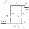
- Fig. 2 shows an embodiment of a multiphase flow meter apparatus 10 according to a second embodiment of the invention.
- the apparatus 10 comprises a linear or substantially linear first conduit 12.
- the first conduit 12 comprises an inlet 19 at one end. At a second end 20 opposite the inlet 19, the first conduit 12 is capped.
- the apparatus 10 also comprises a linear or substantially linear second conduit 13 which comprises an outlet 21 at one end.
- the second conduit 13 is arranged parallel or substantially parallel to the first conduit 12.
- the apparatus 10 further comprises a linear or substantially linear third conduit 14 which extends orthogonally or substantially orthogonally from the first conduit 12 between the inlet 19 and the capped end 20.
- the third conduit 14 is connected to the second conduit 13 at a second end 22 of the second conduit 13 opposite the outlet 21.
- the apparatus 10 also comprises a linear or substantially linear fourth conduit 15 which extends orthogonally or substantially orthogonally from the first conduit 12 between the second conduit 14 and the capped end 20.
- the fourth conduit 15 is connected to the second conduit 13 between the second end 22 and the outlet 21.
- the first 12, second 13, third, 14 and fourth 15 conduits are co-planar or substantially co-planar, and when the apparatus 10 is in operation the plane in which the conduits 13-15 are arranged is vertically or substantially vertically orientated so that the first 12 and second 13 conduits assume a horizontal or substantially horizontal orientation, and the third 14 and fourth 15 conduits assume a vertical or substantially vertical orientation.
- a multiphase fluid will enter the apparatus 10 via the inlet 19.
- the horizontally flowing multiphase fluid stream will be split into a first sub-stream which will flow vertically in conduit 14 and into a second sub-stream which will continue to flow horizontally in conduit 12 and eventually enter conduit 15.
- conduit 14 Due to the horizontal configuration of conduit 12 and the vertical configuration of conduit 14, and due to the higher impulse of liquids than gases and the fact that liquid will tend to flow at the bottom of conduit 12, conduit 14 will sample more gas than conduit 15 and, consequently, the liquid loading in conduit 15 will be higher than in conduit 14.
- the GVF of the sub-stream flowing through conduit 14 will normally be higher than the GVF of the sub-stream flowing through conduit 15.
- Conduits 13 and 15 may in general have any orientation, but by arranging conduit 13 and 15 parallel to conduit 12 and 14, respectively, a compact design of the apparatus can be achieved.
- conduits 12-15 form a separation module 18 of the apparatus 10 arranged to at least partially separate the multiphase stream into a first sub-stream comprising a gas fraction and a second sub-stream comprising a liquid fraction.
- the first conduit 12 will act as an inlet conduit of the separation module 18.
- Conduit 14 will act as a first measuring or separation conduit forming a first conduit path of the separation module 18 of the apparatus 10, and conduit 15 will act as a second measuring or separation conduit forming a second conduit path of the separation module 18, which first and second conduit paths run side by side in a parallel, i.e. non-serial, configuration.
- the sub-streams will be re-joined in conduit 13 and exit the apparatus 10 via outlet 21. Consequently, conduit 13 will act as an outlet conduit of the separation module 18.
- a metering device 6, 7; 16, 17 being able to acquire multiphase and wet gas measurements within the full GVF range of 0-100% is arranged in each measuring conduit 4, 5; 14, 15.
- the phase splitting in the separation module need not be perfect and the unpredictability associated with subsea applications as to GVF:s in the sub-streams can be handled.
- the first phase metering device 6; 16 may for example be a dual-phase meter, and the second phase metering device 7; 17 may be a full range electromagnetic, microwave type multiphase meter. Due to the relatively low GVF of the sub-stream flowing through measuring conduit 5; 15 during normal operation conditions, a relatively accurate water-in-liquid ratio (WLR) measurement for the low GVF sub-stream can be achieved.
- WLR water-in-liquid ratio
- a rough phase splitting module can be achieved using standard piping or similar that is uncontroversial to use subsea.
- the metering device 6, 7; 16, 17 in each measuring conduit 4, 5; 14, 15 is capable of handling the imperfect phase splitting, but at the same time exploits that better WLR and liquid rate measurements can be achieved in the sub-stream flowing through measuring conduit 5; 15.
- the WLR is assumed to be equal in both sub-streams, but if this in some rare case is questionable, a mixing element (not shown in Fig. 1 and Fig. 2 ) may be arranged upstream of the measuring conduits 4, 5; 14, 15.
- the apparatus 1; 10 will provide a compact design and the proposed solution will be shorter in length than a standard single conduit in-line solution, and only marginally wider.
- the apparatus 1; 10 will still function as an MPFM even if the splitting module is not capable of phase-splitting the main flow and the GVF becomes equal in both sub-flows, as may sometimes happen in subsea applications.
- the performance of the apparatus 1; 10 will then be comparable to that of a multiphase meter operating at the same GVF.
- Another problem associated with subsea application is scalability. Increasing flows require that larger pipe dimensions in the phase meters are used. For an electromagnetic, microwave type multiphase meter this may be a problem since this means that the microwave antennas will become positioned further apart, thus resulting in a weaker signal. This problem is amplified if the water phase has a high salinity.
- the apparatus 1 allows a small-diameter electromagnetic, microwave type multiphase meter 7 to be maintained, while scaling of the flow is handled by increasing the diameter of the dual-phase meter 6.
- a dual-phase meter 6 which is not affected by scaling problems, can be used in conduit 4.
- a dual-phase meter 6 is used in conduit 4
- an electromagnetic, microwave type multiphase meter 7 is used in conduit 5
- the cross-sectional area of dual-phase meter 6 is arranged to be larger than the cross-sectional area of electromagnetic, microwave type multiphase meter 7.
- the multiphase meter 7 can typically be a 2 inch diameter meter and the dual-phase meter 6 can be freely sized according to the flow requirements.
- the minimum cross-sectional flow area of the first separation conduit 14 and the first metering device 16 arranged therein is larger than the minimum cross-sectional flow area of the second separation conduit 15 and the second metering device 17 arranged therein.
- the diameter of the cross-sectional flow area of the first and second metering devices 16, 17 is 5" and 3", respectively.
Landscapes
- Physics & Mathematics (AREA)
- General Physics & Mathematics (AREA)
- Chemical & Material Sciences (AREA)
- Fluid Mechanics (AREA)
- Health & Medical Sciences (AREA)
- Life Sciences & Earth Sciences (AREA)
- Engineering & Computer Science (AREA)
- Analytical Chemistry (AREA)
- Biochemistry (AREA)
- General Health & Medical Sciences (AREA)
- Immunology (AREA)
- Pathology (AREA)
- Electromagnetism (AREA)
- Chemical Kinetics & Catalysis (AREA)
- General Chemical & Material Sciences (AREA)
- Oil, Petroleum & Natural Gas (AREA)
- Food Science & Technology (AREA)
- Medicinal Chemistry (AREA)
- Measuring Volume Flow (AREA)
Description
- The present invention relates to a separation type multiphase flow meter apparatus comprising a separation module arranged to at least partially separate a multiphase stream comprising water, hydrocarbon liquid and hydrocarbon gas into a first sub-stream comprising a gas fraction and a second sub-stream comprising a liquid fraction.
- The present invention relates to a hydrocarbon multiphase flow meter (MPFM), i.e. an apparatus for measuring the individual flow rates of hydrocarbon liquid, water and hydrocarbon gas in a multiphase hydrocarbon flow. In particular, the present invention relates to a separation type MPFM.
- In this specification the terms "oil" and "gas" will be used to denote hydrocarbons which are in the liquid and gaseous state, respectively, at the prevailing temperature and pressure conditions, and the term "phase" will be used to denote one constituent of gas, oil and water in a mixture of any number of the three.
- Separation type MPFMs are discussed, for example, in section 7.1.2 of HANDBOOK OF MULTIPHASE FLOW METERING, Rev. 2, March 2005 (ISBN-82-91341-89-3). In a separation type MPFM, a complete or partial separation of the multiphase hydrocarbon flow is performed in a separation stage or module, followed by in-line measurements of each of the three phases. In a partial separation type MPFM, which is discussed in section 7.1.2.2 of the above-mentioned HANDBOOK, only a part of the gas in the multiphase flow is separated into a secondary, gas measurement loop, while the rest of the flow is guided through a main, liquid measurement loop. Since the separation is only partial, one must expect some liquid (oil and water) to travel with the gas through the secondary measurement loop, which then calls for a wet gas meter to be used in this loop. The multiphase flow going through the main measurement loop will have a reduced gas-volume-fraction, GVF, and the individual flow rates of the phases in the main measurement loop can thereby be measured using a conventional multi-phase meter.
- However, this configuration is not suited for subsea use. In particular, use of conventional multi-phase and wetgas meters in the measurement loops requires the separation stage to be efficient enough to ensure a GVF in the respective measurement loop to be above and below, respectively, a GVF threshold, e.g. 95%. This, in turn, requires an active regulation of the separation module, which normally is not an option in subsea applications. Also, the configuration is not suitable when there are slugs in the hydrocarbon flow, as is common in subsea applications, since the required GVF operational range required by conventional multi-phase and wetgas meters cannot be guaranteed under such circumstances.
- In summary, in order to guarantee the GVF operational range required by a conventional multi-phase meter, the configuration suggested in section 7.1.2.2 of the above-mentioned HANDBOOK may, in many applications, require a large, actively regulated separation module of a type which is not an option in subsea applications.
-
EP1899687A1 relates to an apparatus for determining a characteristic of a multiphase fluid flow within a pipe, the apparatus comprising: a separating portion for separating the fluid into a gas component and a liquid component and directing said gas component to flow within a gas leg portion of the pipe and said liquid component to flow within a liquid leg portion of the pipe. - With the abovementioned challenges and known solutions in mind, the present invention seeks to bring forward a simple separation type MPFM which is especially suited for subsea use.
- The invention relates to a separation type multiphase flow meter apparatus comprising a separation module arranged to at least partially separate a multiphase stream comprising water, hydrocarbon liquid and hydrocarbon gas into a first sub-stream comprising a gas fraction and a second sub-stream comprising a liquid fraction. The apparatus further comprises a first metering device for measuring the flow rate of the first sub-stream; and a second metering device for measuring the phase fraction and the flow rate of the second sub-stream, wherein the second metering device is arranged to measure the water-in-liquid ratio (WLR) of the second sub-stream, wherein the apparatus is arranged to use the WLR measured by the second metering device as a measure also for the WLR of the first sub-stream, and wherein the cross-sectional flow area of the first metering device is larger than the cross-sectional flow area of the second metering device.
- The first sub-stream may comprise a gas fraction and a liquid fraction, and the first metering device may be arranged to measure the gas and liquid flow rates of the first sub-stream.
- In the first sub-stream the gas fraction may be larger than the liquid fraction, i.e. the first sub-stream may comprise for the most part a gas fraction, and in the second sub-stream the liquid fraction may be larger than the gas fraction, i.e. the second sub-stream may comprise for the most part a liquid fraction.
- The first and second metering devices may be arranged to acquire multiphase and wet gas measurements within the gas-volume-fraction (GVF) range of 0-100%.
- The first metering device may be a dual-phase meter, e.g. configured to measure gas and liquid mass and volume flow rates, and the second metering device may advantageously be a multiphase meter, e.g. an electromagnetic, microwave type multiphase meter.
- The separation module comprises:
- an inlet conduit configured to receive, at an inlet, the multiphase stream;
- a first measuring or separation conduit configured to receive, from the inlet conduit, said first sub-stream, in which first measuring conduit the first metering device is arranged;
- a second measuring or separation conduit configured to receive, from the inlet conduit, said second sub-stream, in which second measuring conduit the second metering device is arranged; and
- an outlet conduit configured to receive the first sub-stream from the first measuring conduit and the second sub-stream from the second measuring conduit, and to output, at an outlet, the re-joined multiphase stream,
- This will provide a partial separation type multiphase meter apparatus having a simple and robust design which does not require active control of the separation process. Advantageously, both the first and second metering devices are configured to handle a GVF within the range of 0 %≤ GVF ≤ 100 %. This will allow the apparatus to handle situation and be fully functional also when there is limited or no gas-liquid separation, e.g. when slugs occur in the system.
- The design will also allow the separation module to be made from standard subsea piping elements, which may be advantageous since such elements are well known and qualified for subsea use and development.
- The second measuring conduit may extend orthogonally or substantially orthogonally from the inlet conduit co-planar with and downstream of the first measuring conduit.
- The outlet conduit may be arranged in parallel with the inlet conduit.
- Generally, a multiphase meter has limitations when it comes to scalability. If the cross-sectional flow area of the multiphase meter is made large to accommodate a large flow, the transmitted signals from the multiphase meter, which, for example, can be electromagnetic signals or gamma photons of lower energy, may deteriorate and/or attenuate. However, the apparatus according to the present invention allows a small-diameter multiphase meter to be used in the second measuring conduit, while scaling of the flow can be handled by increasing the diameter of the dual-phase meter, which, by virtue of utilising the WLR signal from the multiphase meter, can provide accurate flow rate values for the sub-stream in the first measuring conduit.
- Scalability can particularly be a challenge when the multiphase flow contains high salinity water (for example water having a salinity weight percent above 13%), and the present invention will be particularly relevant in such situations since even moderate size meters (e.g. having a bore diameter of 4") can be prohibited by high signal attenuation caused by high salinity water. However, by having a small-diameter multiphase meter on the second measuring conduit, adequate signal transmission, and thereby adequate WLR measurement, can be achieved for high salinity water applications.
- The diameter of the cross-sectional flow area of the first and second metering devices may for example be 5" and 3", respectively.
- For the intention of making a working multiphase meter apparatus for a multiphase flow comprising high salinity water, the degree of partial phase splitting is not strictly relevant since it is the reduced inner diameter in the second measuring device that is the key element for this. Partial separation multiphase meter apparatuses have previously not been aimed at handling the scalability challenge associated with multiphase flows comprising high salinity water.
- In addition to scalability, a second advantage achieved of the present invention is that it allows for potentially more accurate measurement of liquid properties (e.g. WLR and water salinity) by the multiphase meter in the second measuring conduit since less gas will be present there. This makes the current invention relevant not only for high salinity water wells, but also for any application and/or well where a high gas fraction makes it challenging to achieve sufficiently accurate measurement of WLR and water salinity using a single standard in-line multiphase meter. The present invention is also relevant in situations where it is not practical to install a full-blown separation device capable of achieving the separation quality necessary for existing partial separation multiphase meters.
- According to one aspect of the invention, the separation module may comprise an inlet conduit, an outlet conduit and first and second measuring or separation conduits arranged side by side between and in fluid communication with the inlet and outlet conduits, wherein the first metering device is arranged in the first measuring conduit, which forms a conduit path for the first sub-stream, and wherein the second metering device is arranged in the second measuring conduit, which forms a conduit path for the second sub-stream.
- When the separation module is in use, the inlet conduit and the outlet conduit may have a horizontal or substantially horizontal orientation, and the first and second measuring conduits may have a vertical or substantially vertical orientation.
- The conduits of the separation module may be made from subsea piping elements, e.g. subsea grade piping or ordinary subsea piping elements. As stated above, using such elements may be advantageous since they are well known and qualified for subsea use and development.
- Following drawing is appended to facilitate the understanding of the invention:
-
Fig. 1 shows a separation type multiphase flow meter apparatus according to one embodiment of the invention. -
Fig. 2 shows a separation type multiphase flow meter apparatus according to a second embodiment of the invention. - It should be understood, however, that the drawings are not intended to limit the invention to the subject-matter depicted in the drawings.
- In the drawings, like reference numerals have been used to indicate common parts, elements or features unless otherwise explicitly stated or implicitly understood by the context.
-
Fig. 1 shows an embodiment of a separation type multiphase flow meter apparatus 1 according to the invention. - The apparatus 1 comprises an
inlet conduit 2 and anoutlet conduit 3. The apparatus 1 further comprises first and second measuring orseparation conduits 4, 5 being arranged side by side between and in fluid communication with the inlet andoutlet conduits measuring conduit 5 forms a second conduit path of the apparatus 1, which first and second conduit paths run side by side in a parallel, i.e. non-serial, configuration. - In operation, a multiphase fluid will enter the apparatus 1 via
inlet conduit 2 and be split into two sub-streams in measuringconduits 4 and 5, which sub-streams will be re-joined inoutlet conduit 3 and exit the apparatus 1 via this conduit, as is indicated by the arrows inFig. 1 . Conduits 2-5 form aseparation module 8 of the apparatus 1 arranged to at least partially separate the multiphase stream comprising water, hydrocarbon liquid and hydrocarbon gas into a first sub-stream comprising a gas fraction and a second sub-stream comprising a liquid fraction. - In the embodiment shown in
Fig. 1 , the input andoutput conduits conduits 4, 5 are substantially vertical. The conduits 2-5 may advantageously be made from ordinary or standard subsea piping, e.g. duplex pipes, providing a simple, rugged separation module design suitable for subsea applications. - The first measuring conduit 4 is arranged upstream of the
second measuring conduit 5 and due to the higher impulse of liquids than gases, and the fact that liquid will tend to flow at the bottom ofinlet conduit 2, the liquid loading in measuringconduit 5 will be higher than in measuring conduit 4. In other words, the GVF of the sub-stream flowing through conduit 4 will normally be higher than the GVF of the sub-stream flowing throughconduit 5. -
Fig. 2 shows an embodiment of a multiphaseflow meter apparatus 10 according to a second embodiment of the invention. - The
apparatus 10 comprises a linear or substantially linearfirst conduit 12. Thefirst conduit 12 comprises aninlet 19 at one end. At asecond end 20 opposite theinlet 19, thefirst conduit 12 is capped. - The
apparatus 10 also comprises a linear or substantially linearsecond conduit 13 which comprises anoutlet 21 at one end. Thesecond conduit 13 is arranged parallel or substantially parallel to thefirst conduit 12. - The
apparatus 10 further comprises a linear or substantially linearthird conduit 14 which extends orthogonally or substantially orthogonally from thefirst conduit 12 between theinlet 19 and the cappedend 20. Thethird conduit 14 is connected to thesecond conduit 13 at asecond end 22 of thesecond conduit 13 opposite theoutlet 21. Theapparatus 10 also comprises a linear or substantially linearfourth conduit 15 which extends orthogonally or substantially orthogonally from thefirst conduit 12 between thesecond conduit 14 and the cappedend 20. Thefourth conduit 15 is connected to thesecond conduit 13 between thesecond end 22 and theoutlet 21. - The first 12, second 13, third, 14 and fourth 15 conduits are co-planar or substantially co-planar, and when the
apparatus 10 is in operation the plane in which the conduits 13-15 are arranged is vertically or substantially vertically orientated so that the first 12 and second 13 conduits assume a horizontal or substantially horizontal orientation, and the third 14 and fourth 15 conduits assume a vertical or substantially vertical orientation. - In operation, a multiphase fluid will enter the
apparatus 10 via theinlet 19. At thethird conduit 14, the horizontally flowing multiphase fluid stream will be split into a first sub-stream which will flow vertically inconduit 14 and into a second sub-stream which will continue to flow horizontally inconduit 12 and eventually enterconduit 15. Due to the horizontal configuration ofconduit 12 and the vertical configuration ofconduit 14, and due to the higher impulse of liquids than gases and the fact that liquid will tend to flow at the bottom ofconduit 12,conduit 14 will sample more gas thanconduit 15 and, consequently, the liquid loading inconduit 15 will be higher than inconduit 14. In other words, the GVF of the sub-stream flowing throughconduit 14 will normally be higher than the GVF of the sub-stream flowing throughconduit 15. -
Conduits conduit conduit - Consequently, in
Fig. 2 conduits 12-15 form aseparation module 18 of theapparatus 10 arranged to at least partially separate the multiphase stream into a first sub-stream comprising a gas fraction and a second sub-stream comprising a liquid fraction. Thefirst conduit 12 will act as an inlet conduit of theseparation module 18.Conduit 14 will act as a first measuring or separation conduit forming a first conduit path of theseparation module 18 of theapparatus 10, andconduit 15 will act as a second measuring or separation conduit forming a second conduit path of theseparation module 18, which first and second conduit paths run side by side in a parallel, i.e. non-serial, configuration. The sub-streams will be re-joined inconduit 13 and exit theapparatus 10 viaoutlet 21. Consequently,conduit 13 will act as an outlet conduit of theseparation module 18. - In the following, reference will be made to both
Fig. 1 andFig. 2 . - A
metering device 6, 7; 16, 17 being able to acquire multiphase and wet gas measurements within the full GVF range of 0-100% is arranged in each measuringconduit 4, 5; 14, 15. By choosing such metering devices, the phase splitting in the separation module need not be perfect and the unpredictability associated with subsea applications as to GVF:s in the sub-streams can be handled. - The first
phase metering device 6; 16 may for example be a dual-phase meter, and the second phase metering device 7; 17 may be a full range electromagnetic, microwave type multiphase meter. Due to the relatively low GVF of the sub-stream flowing through measuringconduit 5; 15 during normal operation conditions, a relatively accurate water-in-liquid ratio (WLR) measurement for the low GVF sub-stream can be achieved. - For dual-
phase meter 6; 16 WLR measuring is not necessary since dual-phase meter 6; 16 only measures gas and liquid rates and can rely on WLR measurements from multiphase meter 7; 17. Relevant values, e.g. gamma densitometer and differential pressure values of dual-phase meter 6; 16, are transmitted to and processed by the electronics in multiphase meter 7; 17. - According to one aspect of the invention, a rough phase splitting module can be achieved using standard piping or similar that is uncontroversial to use subsea. At the same time, the
metering device 6, 7; 16, 17 in each measuringconduit 4, 5; 14, 15 is capable of handling the imperfect phase splitting, but at the same time exploits that better WLR and liquid rate measurements can be achieved in the sub-stream flowing through measuringconduit 5; 15. - As discussed above, the WLR is assumed to be equal in both sub-streams, but if this in some rare case is questionable, a mixing element (not shown in
Fig. 1 andFig. 2 ) may be arranged upstream of the measuringconduits 4, 5; 14, 15. - The apparatus 1; 10 will provide a compact design and the proposed solution will be shorter in length than a standard single conduit in-line solution, and only marginally wider.
- It should be noted that the apparatus 1; 10 according to the invention will still function as an MPFM even if the splitting module is not capable of phase-splitting the main flow and the GVF becomes equal in both sub-flows, as may sometimes happen in subsea applications. The performance of the apparatus 1; 10 will then be comparable to that of a multiphase meter operating at the same GVF.
- Another problem associated with subsea application is scalability. Increasing flows require that larger pipe dimensions in the phase meters are used. For an electromagnetic, microwave type multiphase meter this may be a problem since this means that the microwave antennas will become positioned further apart, thus resulting in a weaker signal. This problem is amplified if the water phase has a high salinity.
- It is known to alleviate this problem by substituting a single electromagnetic, microwave type multiphase meter for a plurality of smaller diameter meters arranged in parallel.
- However, the apparatus according to the present invention allows an alternative solution. In particular, the apparatus 1 allows a small-diameter electromagnetic, microwave type multiphase meter 7 to be maintained, while scaling of the flow is handled by increasing the diameter of the dual-
phase meter 6. By assuming that the WLR is the same in bothconduits 4 and 5, a dual-phase meter 6, which is not affected by scaling problems, can be used in conduit 4. Consequently, according to one embodiment of the apparatus, a dual-phase meter 6 is used in conduit 4, an electromagnetic, microwave type multiphase meter 7 is used inconduit 5, and the cross-sectional area of dual-phase meter 6 is arranged to be larger than the cross-sectional area of electromagnetic, microwave type multiphase meter 7. For example, the multiphase meter 7 can typically be a 2 inch diameter meter and the dual-phase meter 6 can be freely sized according to the flow requirements. - In the embodiment shown in
Fig. 2 , the minimum cross-sectional flow area of thefirst separation conduit 14 and thefirst metering device 16 arranged therein is larger than the minimum cross-sectional flow area of thesecond separation conduit 15 and the second metering device 17 arranged therein. In this embodiment, the diameter of the cross-sectional flow area of the first andsecond metering devices 16, 17 is 5" and 3", respectively. - In the preceding description, various aspects of the apparatus according to the invention have been described with reference to the illustrative embodiment. For purposes of explanation, specific numbers, systems and configurations were set forth in order to provide a thorough understanding of the apparatus and its workings. However, this description is not intended to be construed in a limiting sense. Various modifications and variations of the illustrative embodiment, as well as other embodiments of the apparatus, which are apparent to person skilled in the art to which the disclosed subject-matter pertains, are deemed to lie within the scope of the present invention as defined by the following claims.
Claims (10)
- A separation type multiphase flow meter apparatus (1; 10) comprising a separation module (8; 18) arranged to at least partially separate a multiphase stream comprising water, hydrocarbon liquid and hydrocarbon gas into a first sub-stream comprising a gas fraction and a second sub-stream comprising a liquid fraction, wherein the apparatus (1; 10) further comprises:- a first metering device (6; 16) for measuring the flow rate of the first sub-stream; and- a second metering device (7; 17) for measuring the phase fraction and the flow rate of the second sub-stream,wherein the second metering device (7; 17) is arranged to measure the water-in-liquid ratio (WLR) of the second sub-stream, wherein the apparatus (1; 10) is arranged to use the water-in-liquid ratio (WLR) measured by the second metering device (7; 17) as a measure also for the water-in-liquid ratio (WLR) of the first sub-stream,and wherein the cross-sectional flow area of the first metering device (6; 16) is larger than the cross-sectional flow area of the second metering device (7; 17)wherein the separation module (8; 18) comprises:- an inlet conduit (2; 12) configured to receive, at an inlet (19), the multiphase stream;- a first measuring conduit (4; 14) configured to receive, from the inlet conduit (2; 12), said first sub-stream, in which first measuring conduit (4; 14) the first metering device (6; 16) is arranged;- a second measuring conduit (5; 15) configured to receive, from the inlet conduit (2; 12), said second sub-stream, in which second measuring conduit (5; 15) the second metering device (7; 17) is arranged; and- an outlet conduit (3; 13) configured to receive the first sub-stream from the first measuring conduit (4; 14) and the second sub-stream from the second measuring conduit (5; 15), and to output, at an outlet (21), the re-joined multiphase stream,characterised in thatthe first measuring conduit (4; 14) extends orthogonally or substantially orthogonally from the inlet conduit (2; 12); and wherein, when the apparatus (1; 10) is in operation, the inlet conduit (2; 12) is configured to have a horizontal or substantially horizontal orientation and the first measuring conduit (4; 14) is configured to extend vertically upwardly or substantially vertically upwardly from the inlet conduit (2; 12) allowing the first sub-stream to be conveyed vertically upwardly or substantially vertically upwardly in the first measuring conduit (4; 14), and allowing the second sub-stream to be conveyed horizontally or substantially horizontally in the inlet conduit (2; 12) downstream of the first measuring conduit (4; 14).
- The apparatus (1; 10) according to claim 1, characterised in that the first sub-stream comprises a gas fraction and a liquid fraction, and in that first metering device (6; 16) is arranged to measure the gas and liquid flow rates of the first sub-stream.
- The apparatus (1; 10) according to any one of claims 1 and 2, characterised in that the first and second metering devices (6; 16; 7; 17) are arranged to acquire multiphase and wet gas measurements within the gas-volume-fraction (GVF) range of 0-100%.
- The apparatus (1) according to any one of the preceding claims, characterised in that the first metering device (6; 16) is a dual-phase meter and the second metering device (7; 17) is an electromagnetic, microwave type multiphase meter.
- The apparatus (1) according to any one of the preceding claims, characterised in that the second measuring conduit (5; 15) extends orthogonally or substantially orthogonally from the inlet conduit (2; 12) co-planar with and downstream of the first measuring conduit (4; 14).
- The apparatus (1) according to claim 5, characterised in that the outlet conduit (3; 13) is arranged in parallel with the inlet conduit (2; 12).
- The apparatus (1) according to any one of claims 2-6, characterised in that the inlet conduit (2; 12), the outlet conduit (3; 13), the first measuring conduit (4; 14) and the second measuring conduit (5; 15) are made from subsea piping elements.
- The apparatus (1) according to any one of claims 1-4, characterised in that the separation module (8) comprises an inlet conduit (2), an outlet conduit (3) and first and second measuring conduits (4, 5) arranged side by side between and in fluid communication with the inlet and outlet conduits (2, 3), wherein the first metering device (6) is arranged in the first measuring conduit (4), which forms a conduit path for the first sub-stream, and wherein the second metering device (7) is arranged in the second measuring conduit (5), which forms a conduit path for the second sub-stream.
- The apparatus (1) according to claim 8, characterised in that the inlet conduit (2) and the outlet conduit (3) have a generally horizontal orientation, and the first and second measuring conduits (4, 5) have a generally vertical orientation when the apparatus (1) is in use.
- The apparatus (1) according to any one of claims 8 and 9, characterised in that the conduits (2-5) are made from subsea piping elements.
Applications Claiming Priority (2)
| Application Number | Priority Date | Filing Date | Title |
|---|---|---|---|
| NO20171416A NO347826B1 (en) | 2017-08-31 | 2017-08-31 | Separation type multiphase flow meter apparatus |
| PCT/EP2018/073472 WO2019043160A1 (en) | 2017-08-31 | 2018-08-31 | Separation type multiphase flow meter apparatus |
Publications (2)
| Publication Number | Publication Date |
|---|---|
| EP3676574A1 EP3676574A1 (en) | 2020-07-08 |
| EP3676574B1 true EP3676574B1 (en) | 2025-01-08 |
Family
ID=63490459
Family Applications (1)
| Application Number | Title | Priority Date | Filing Date |
|---|---|---|---|
| EP18765083.3A Active EP3676574B1 (en) | 2017-08-31 | 2018-08-31 | Separation type multiphase flow meter apparatus |
Country Status (4)
| Country | Link |
|---|---|
| US (1) | US11493375B2 (en) |
| EP (1) | EP3676574B1 (en) |
| NO (1) | NO347826B1 (en) |
| WO (1) | WO2019043160A1 (en) |
Citations (1)
| Publication number | Priority date | Publication date | Assignee | Title |
|---|---|---|---|---|
| EP1899687B1 (en) * | 2005-07-07 | 2010-09-22 | Expro Meters, Inc. | Multi-phase flow measurement system having a fluid separator |
Family Cites Families (9)
| Publication number | Priority date | Publication date | Assignee | Title |
|---|---|---|---|---|
| US5048348A (en) * | 1989-02-14 | 1991-09-17 | Texaco Inc. | Fluid flow volumetric determination apparatus and method |
| US5390547A (en) * | 1993-11-16 | 1995-02-21 | Liu; Ke-Tien | Multiphase flow separation and measurement system |
| GB9523278D0 (en) | 1995-11-14 | 1996-01-17 | Jordan Kent Metering Systems L | A wet gas multiphase meter |
| CN2349553Y (en) * | 1998-07-28 | 1999-11-17 | 窦剑文 | Gas-liquid polyphase flow flowmeter |
| GB9910160D0 (en) * | 1999-04-30 | 1999-06-30 | Framo Eng As | Apparatus and method for fluid measurement |
| US7654151B2 (en) * | 2005-05-10 | 2010-02-02 | Agar Corporation Ltd. | Method and apparatus for measuring multi-streams and multi-phase flow |
| US8641813B2 (en) * | 2005-07-07 | 2014-02-04 | Expro Meters, Inc. | System and method for optimizing a gas/liquid separation process |
| US8869627B2 (en) * | 2012-07-09 | 2014-10-28 | King Fahd University Of Petroleum And Minerals | Multi-phase flow metering system |
| US9114332B1 (en) * | 2012-07-23 | 2015-08-25 | Herbert Liu | Multiphase flow measurement apparatus utilizing phase separation |
-
2017
- 2017-08-31 NO NO20171416A patent/NO347826B1/en unknown
-
2018
- 2018-08-31 WO PCT/EP2018/073472 patent/WO2019043160A1/en not_active Ceased
- 2018-08-31 US US16/643,497 patent/US11493375B2/en active Active
- 2018-08-31 EP EP18765083.3A patent/EP3676574B1/en active Active
Patent Citations (1)
| Publication number | Priority date | Publication date | Assignee | Title |
|---|---|---|---|---|
| EP1899687B1 (en) * | 2005-07-07 | 2010-09-22 | Expro Meters, Inc. | Multi-phase flow measurement system having a fluid separator |
Also Published As
| Publication number | Publication date |
|---|---|
| EP3676574A1 (en) | 2020-07-08 |
| US11493375B2 (en) | 2022-11-08 |
| US20200209035A1 (en) | 2020-07-02 |
| NO20171416A1 (en) | 2019-03-01 |
| WO2019043160A1 (en) | 2019-03-07 |
| NO347826B1 (en) | 2024-04-08 |
| BR112020004237A2 (en) | 2020-09-01 |
Similar Documents
| Publication | Publication Date | Title |
|---|---|---|
| DK1305579T3 (en) | GAUGE FOR MEASURING AND MULTIFASEFLUIDER wet gas | |
| US6532826B1 (en) | Measuring device for the gas-liquid flow rate of multiphase fluids | |
| Asheim | MONA, an accurate two-phase well flow model based on phase slippage | |
| US10677627B2 (en) | Representative sampling of multiphase fluids | |
| US5741977A (en) | High void fraction multi-phase fluid flow meter | |
| CN101900581B (en) | Gas/liquid flow rate determination | |
| US10655997B2 (en) | Flowmeter for two-phase fluid with simultaneous or alternating measurement of the gas phase and the liquid phase | |
| US20170315026A1 (en) | A method and apparatus for the isokinetic sampling of a multiphase stream | |
| US4574837A (en) | Method and apparatus for splitting two-phase gas-liquid flows having a known flow profile | |
| NO20131319A1 (en) | Method and apparatus for measuring individual components of a multiphase fluid | |
| US11493375B2 (en) | Separation type multiphase flowmeter with separate flow metering devices with different cross-sectional areas | |
| NO20131320A1 (en) | Method and apparatus for measuring individual components of a multiphase fluid | |
| US2984105A (en) | Device for measuring the quantities of solids contained in flowing mediae | |
| Pao et al. | Numerical investigation of gas separation in T-junction | |
| KR20190027788A (en) | Flow meter | |
| US11247145B2 (en) | Gas—liquid flow splitting (GLFS) system | |
| Westra et al. | Qualification of inline dewatering technology | |
| RU2597019C2 (en) | Apparatus and method for measuring flow-rate of different fluids present in multiphase streams | |
| BR112020004237B1 (en) | SEPARATION TYPE MULTIPHASE FLOW METER | |
| Voogd et al. | A novel compact and controllable inline separator: field and laboratory tests | |
| NO20240077A1 (en) | Differential pressure-based mass flow meter for fluid and fluid mixture metering | |
| Leggett et al. | Multiphase Flowmeter Successfully Measures Three-Phase Flow at Extremely High Gas-Volume Fractions—Gulf of Suez, Egypt | |
| Potten et al. | Real-Time Composition Measurement for Fiscal, Allocation and Process Optimization | |
| RU2230310C2 (en) | Oil metering assembly | |
| Tuss | Wet gas multi-phase measurement |
Legal Events
| Date | Code | Title | Description |
|---|---|---|---|
| STAA | Information on the status of an ep patent application or granted ep patent |
Free format text: STATUS: UNKNOWN |
|
| STAA | Information on the status of an ep patent application or granted ep patent |
Free format text: STATUS: THE INTERNATIONAL PUBLICATION HAS BEEN MADE |
|
| PUAI | Public reference made under article 153(3) epc to a published international application that has entered the european phase |
Free format text: ORIGINAL CODE: 0009012 |
|
| STAA | Information on the status of an ep patent application or granted ep patent |
Free format text: STATUS: REQUEST FOR EXAMINATION WAS MADE |
|
| 17P | Request for examination filed |
Effective date: 20200304 |
|
| AK | Designated contracting states |
Kind code of ref document: A1 Designated state(s): AL AT BE BG CH CY CZ DE DK EE ES FI FR GB GR HR HU IE IS IT LI LT LU LV MC MK MT NL NO PL PT RO RS SE SI SK SM TR |
|
| AX | Request for extension of the european patent |
Extension state: BA ME |
|
| DAV | Request for validation of the european patent (deleted) | ||
| DAX | Request for extension of the european patent (deleted) | ||
| STAA | Information on the status of an ep patent application or granted ep patent |
Free format text: STATUS: EXAMINATION IS IN PROGRESS |
|
| 17Q | First examination report despatched |
Effective date: 20220610 |
|
| GRAP | Despatch of communication of intention to grant a patent |
Free format text: ORIGINAL CODE: EPIDOSNIGR1 |
|
| STAA | Information on the status of an ep patent application or granted ep patent |
Free format text: STATUS: GRANT OF PATENT IS INTENDED |
|
| RIC1 | Information provided on ipc code assigned before grant |
Ipc: G01N 9/24 20060101ALN20240724BHEP Ipc: G01N 22/04 20060101ALI20240724BHEP Ipc: G01N 33/28 20060101ALI20240724BHEP Ipc: G01F 1/34 20060101ALI20240724BHEP Ipc: G01F 5/00 20060101ALI20240724BHEP Ipc: G01F 15/08 20060101ALI20240724BHEP Ipc: G01F 1/74 20060101AFI20240724BHEP |
|
| INTG | Intention to grant announced |
Effective date: 20240801 |
|
| RIN1 | Information on inventor provided before grant (corrected) |
Inventor name: GUNDERSEN, KENNETH |
|
| GRAS | Grant fee paid |
Free format text: ORIGINAL CODE: EPIDOSNIGR3 |
|
| GRAA | (expected) grant |
Free format text: ORIGINAL CODE: 0009210 |
|
| STAA | Information on the status of an ep patent application or granted ep patent |
Free format text: STATUS: THE PATENT HAS BEEN GRANTED |
|
| AK | Designated contracting states |
Kind code of ref document: B1 Designated state(s): AL AT BE BG CH CY CZ DE DK EE ES FI FR GB GR HR HU IE IS IT LI LT LU LV MC MK MT NL NO PL PT RO RS SE SI SK SM TR |
|
| REG | Reference to a national code |
Ref country code: GB Ref legal event code: FG4D |
|
| P01 | Opt-out of the competence of the unified patent court (upc) registered |
Free format text: CASE NUMBER: APP_65065/2024 Effective date: 20241209 |
|
| REG | Reference to a national code |
Ref country code: CH Ref legal event code: EP |
|
| REG | Reference to a national code |
Ref country code: DE Ref legal event code: R096 Ref document number: 602018078353 Country of ref document: DE |
|
| REG | Reference to a national code |
Ref country code: IE Ref legal event code: FG4D |
|
| RAP4 | Party data changed (patent owner data changed or rights of a patent transferred) |
Owner name: TECHNIPFMC NORGE AS |
|
| REG | Reference to a national code |
Ref country code: LT Ref legal event code: MG9D |
|
| REG | Reference to a national code |
Ref country code: NL Ref legal event code: MP Effective date: 20250108 |
|
| REG | Reference to a national code |
Ref country code: AT Ref legal event code: MK05 Ref document number: 1758594 Country of ref document: AT Kind code of ref document: T Effective date: 20250108 |
|
| PG25 | Lapsed in a contracting state [announced via postgrant information from national office to epo] |
Ref country code: NL Free format text: LAPSE BECAUSE OF FAILURE TO SUBMIT A TRANSLATION OF THE DESCRIPTION OR TO PAY THE FEE WITHIN THE PRESCRIBED TIME-LIMIT Effective date: 20250108 |
|
| PG25 | Lapsed in a contracting state [announced via postgrant information from national office to epo] |
Ref country code: RS Free format text: LAPSE BECAUSE OF FAILURE TO SUBMIT A TRANSLATION OF THE DESCRIPTION OR TO PAY THE FEE WITHIN THE PRESCRIBED TIME-LIMIT Effective date: 20250408 |
|
| PG25 | Lapsed in a contracting state [announced via postgrant information from national office to epo] |
Ref country code: FI Free format text: LAPSE BECAUSE OF FAILURE TO SUBMIT A TRANSLATION OF THE DESCRIPTION OR TO PAY THE FEE WITHIN THE PRESCRIBED TIME-LIMIT Effective date: 20250108 |
|
| PG25 | Lapsed in a contracting state [announced via postgrant information from national office to epo] |
Ref country code: PL Free format text: LAPSE BECAUSE OF FAILURE TO SUBMIT A TRANSLATION OF THE DESCRIPTION OR TO PAY THE FEE WITHIN THE PRESCRIBED TIME-LIMIT Effective date: 20250108 |
|
| PG25 | Lapsed in a contracting state [announced via postgrant information from national office to epo] |
Ref country code: ES Free format text: LAPSE BECAUSE OF FAILURE TO SUBMIT A TRANSLATION OF THE DESCRIPTION OR TO PAY THE FEE WITHIN THE PRESCRIBED TIME-LIMIT Effective date: 20250108 |
|
| PG25 | Lapsed in a contracting state [announced via postgrant information from national office to epo] |
Ref country code: IS Free format text: LAPSE BECAUSE OF FAILURE TO SUBMIT A TRANSLATION OF THE DESCRIPTION OR TO PAY THE FEE WITHIN THE PRESCRIBED TIME-LIMIT Effective date: 20250508 |
|
| PG25 | Lapsed in a contracting state [announced via postgrant information from national office to epo] |
Ref country code: HR Free format text: LAPSE BECAUSE OF FAILURE TO SUBMIT A TRANSLATION OF THE DESCRIPTION OR TO PAY THE FEE WITHIN THE PRESCRIBED TIME-LIMIT Effective date: 20250108 |
|
| PG25 | Lapsed in a contracting state [announced via postgrant information from national office to epo] |
Ref country code: LV Free format text: LAPSE BECAUSE OF FAILURE TO SUBMIT A TRANSLATION OF THE DESCRIPTION OR TO PAY THE FEE WITHIN THE PRESCRIBED TIME-LIMIT Effective date: 20250108 Ref country code: PT Free format text: LAPSE BECAUSE OF FAILURE TO SUBMIT A TRANSLATION OF THE DESCRIPTION OR TO PAY THE FEE WITHIN THE PRESCRIBED TIME-LIMIT Effective date: 20250508 |
|
| PG25 | Lapsed in a contracting state [announced via postgrant information from national office to epo] |
Ref country code: BG Free format text: LAPSE BECAUSE OF FAILURE TO SUBMIT A TRANSLATION OF THE DESCRIPTION OR TO PAY THE FEE WITHIN THE PRESCRIBED TIME-LIMIT Effective date: 20250108 Ref country code: GR Free format text: LAPSE BECAUSE OF FAILURE TO SUBMIT A TRANSLATION OF THE DESCRIPTION OR TO PAY THE FEE WITHIN THE PRESCRIBED TIME-LIMIT Effective date: 20250409 |
|
| PG25 | Lapsed in a contracting state [announced via postgrant information from national office to epo] |
Ref country code: AT Free format text: LAPSE BECAUSE OF FAILURE TO SUBMIT A TRANSLATION OF THE DESCRIPTION OR TO PAY THE FEE WITHIN THE PRESCRIBED TIME-LIMIT Effective date: 20250108 |
|
| PG25 | Lapsed in a contracting state [announced via postgrant information from national office to epo] |
Ref country code: SE Free format text: LAPSE BECAUSE OF FAILURE TO SUBMIT A TRANSLATION OF THE DESCRIPTION OR TO PAY THE FEE WITHIN THE PRESCRIBED TIME-LIMIT Effective date: 20250108 |
|
| PG25 | Lapsed in a contracting state [announced via postgrant information from national office to epo] |
Ref country code: SM Free format text: LAPSE BECAUSE OF FAILURE TO SUBMIT A TRANSLATION OF THE DESCRIPTION OR TO PAY THE FEE WITHIN THE PRESCRIBED TIME-LIMIT Effective date: 20250108 |
|
| REG | Reference to a national code |
Ref country code: DE Ref legal event code: R097 Ref document number: 602018078353 Country of ref document: DE |
|
| PG25 | Lapsed in a contracting state [announced via postgrant information from national office to epo] |
Ref country code: DK Free format text: LAPSE BECAUSE OF FAILURE TO SUBMIT A TRANSLATION OF THE DESCRIPTION OR TO PAY THE FEE WITHIN THE PRESCRIBED TIME-LIMIT Effective date: 20250108 |
|
| PGFP | Annual fee paid to national office [announced via postgrant information from national office to epo] |
Ref country code: NO Payment date: 20250808 Year of fee payment: 8 |
|
| PGFP | Annual fee paid to national office [announced via postgrant information from national office to epo] |
Ref country code: GB Payment date: 20250703 Year of fee payment: 8 |
|
| PGFP | Annual fee paid to national office [announced via postgrant information from national office to epo] |
Ref country code: FR Payment date: 20250703 Year of fee payment: 8 |
|
| PG25 | Lapsed in a contracting state [announced via postgrant information from national office to epo] |
Ref country code: CZ Free format text: LAPSE BECAUSE OF FAILURE TO SUBMIT A TRANSLATION OF THE DESCRIPTION OR TO PAY THE FEE WITHIN THE PRESCRIBED TIME-LIMIT Effective date: 20250108 Ref country code: EE Free format text: LAPSE BECAUSE OF FAILURE TO SUBMIT A TRANSLATION OF THE DESCRIPTION OR TO PAY THE FEE WITHIN THE PRESCRIBED TIME-LIMIT Effective date: 20250108 |
|
| PG25 | Lapsed in a contracting state [announced via postgrant information from national office to epo] |
Ref country code: RO Free format text: LAPSE BECAUSE OF FAILURE TO SUBMIT A TRANSLATION OF THE DESCRIPTION OR TO PAY THE FEE WITHIN THE PRESCRIBED TIME-LIMIT Effective date: 20250108 |
|
| PG25 | Lapsed in a contracting state [announced via postgrant information from national office to epo] |
Ref country code: SK Free format text: LAPSE BECAUSE OF FAILURE TO SUBMIT A TRANSLATION OF THE DESCRIPTION OR TO PAY THE FEE WITHIN THE PRESCRIBED TIME-LIMIT Effective date: 20250108 |
|
| PLBE | No opposition filed within time limit |
Free format text: ORIGINAL CODE: 0009261 |
|
| STAA | Information on the status of an ep patent application or granted ep patent |
Free format text: STATUS: NO OPPOSITION FILED WITHIN TIME LIMIT |
|
| REG | Reference to a national code |
Ref country code: CH Ref legal event code: L10 Free format text: ST27 STATUS EVENT CODE: U-0-0-L10-L00 (AS PROVIDED BY THE NATIONAL OFFICE) Effective date: 20251119 |
|
| 26N | No opposition filed |
Effective date: 20251009 |
|
| REG | Reference to a national code |
Ref country code: DE Ref legal event code: R119 Ref document number: 602018078353 Country of ref document: DE |
|
| REG | Reference to a national code |
Ref country code: CH Ref legal event code: H13 Free format text: ST27 STATUS EVENT CODE: U-0-0-H10-H13 (AS PROVIDED BY THE NATIONAL OFFICE) Effective date: 20260324 |
|
| PG25 | Lapsed in a contracting state [announced via postgrant information from national office to epo] |
Ref country code: MC Free format text: LAPSE BECAUSE OF FAILURE TO SUBMIT A TRANSLATION OF THE DESCRIPTION OR TO PAY THE FEE WITHIN THE PRESCRIBED TIME-LIMIT Effective date: 20250108 |
|
| PG25 | Lapsed in a contracting state [announced via postgrant information from national office to epo] |
Ref country code: LU Free format text: LAPSE BECAUSE OF NON-PAYMENT OF DUE FEES Effective date: 20250831 |
|
| PG25 | Lapsed in a contracting state [announced via postgrant information from national office to epo] |
Ref country code: CH Free format text: LAPSE BECAUSE OF NON-PAYMENT OF DUE FEES Effective date: 20250831 |