EP3676201B1 - Conveyor skirt system - Google Patents
Conveyor skirt system Download PDFInfo
- Publication number
- EP3676201B1 EP3676201B1 EP18849502.2A EP18849502A EP3676201B1 EP 3676201 B1 EP3676201 B1 EP 3676201B1 EP 18849502 A EP18849502 A EP 18849502A EP 3676201 B1 EP3676201 B1 EP 3676201B1
- Authority
- EP
- European Patent Office
- Prior art keywords
- conveyor
- skirting
- skirting panel
- assembly
- panel
- Prior art date
- Legal status (The legal status is an assumption and is not a legal conclusion. Google has not performed a legal analysis and makes no representation as to the accuracy of the status listed.)
- Active
Links
Images



Classifications
-
- B—PERFORMING OPERATIONS; TRANSPORTING
- B65—CONVEYING; PACKING; STORING; HANDLING THIN OR FILAMENTARY MATERIAL
- B65G—TRANSPORT OR STORAGE DEVICES, e.g. CONVEYORS FOR LOADING OR TIPPING, SHOP CONVEYOR SYSTEMS OR PNEUMATIC TUBE CONVEYORS
- B65G21/00—Supporting or protective framework or housings for endless load-carriers or traction elements of belt or chain conveyors
- B65G21/20—Means incorporated in, or attached to, framework or housings for guiding load-carriers, traction elements or loads supported on moving surfaces
- B65G21/2045—Mechanical means for guiding or retaining the load on the load-carrying surface
- B65G21/2063—Mechanical means for guiding or retaining the load on the load-carrying surface comprising elements not movable in the direction of load-transport
- B65G21/2072—Laterial guidance means
- B65G21/2081—Laterial guidance means for bulk material, e.g. skirts
-
- B—PERFORMING OPERATIONS; TRANSPORTING
- B65—CONVEYING; PACKING; STORING; HANDLING THIN OR FILAMENTARY MATERIAL
- B65G—TRANSPORT OR STORAGE DEVICES, e.g. CONVEYORS FOR LOADING OR TIPPING, SHOP CONVEYOR SYSTEMS OR PNEUMATIC TUBE CONVEYORS
- B65G41/00—Supporting frames or bases for conveyors as a whole, e.g. transportable conveyor frames
-
- B—PERFORMING OPERATIONS; TRANSPORTING
- B65—CONVEYING; PACKING; STORING; HANDLING THIN OR FILAMENTARY MATERIAL
- B65G—TRANSPORT OR STORAGE DEVICES, e.g. CONVEYORS FOR LOADING OR TIPPING, SHOP CONVEYOR SYSTEMS OR PNEUMATIC TUBE CONVEYORS
- B65G15/00—Conveyors having endless load-conveying surfaces, i.e. belts and like continuous members, to which tractive effort is transmitted by means other than endless driving elements of similar configuration
- B65G15/08—Conveyors having endless load-conveying surfaces, i.e. belts and like continuous members, to which tractive effort is transmitted by means other than endless driving elements of similar configuration the load-carrying surface being formed by a concave or tubular belt, e.g. a belt forming a trough
-
- B—PERFORMING OPERATIONS; TRANSPORTING
- B65—CONVEYING; PACKING; STORING; HANDLING THIN OR FILAMENTARY MATERIAL
- B65G—TRANSPORT OR STORAGE DEVICES, e.g. CONVEYORS FOR LOADING OR TIPPING, SHOP CONVEYOR SYSTEMS OR PNEUMATIC TUBE CONVEYORS
- B65G2201/00—Indexing codes relating to handling devices, e.g. conveyors, characterised by the type of product or load being conveyed or handled
- B65G2201/04—Bulk
- B65G2201/042—Granular material
-
- B—PERFORMING OPERATIONS; TRANSPORTING
- B65—CONVEYING; PACKING; STORING; HANDLING THIN OR FILAMENTARY MATERIAL
- B65G—TRANSPORT OR STORAGE DEVICES, e.g. CONVEYORS FOR LOADING OR TIPPING, SHOP CONVEYOR SYSTEMS OR PNEUMATIC TUBE CONVEYORS
- B65G2207/00—Indexing codes relating to constructional details, configuration and additional features of a handling device, e.g. Conveyors
- B65G2207/40—Safety features of loads, equipment or persons
-
- B—PERFORMING OPERATIONS; TRANSPORTING
- B65—CONVEYING; PACKING; STORING; HANDLING THIN OR FILAMENTARY MATERIAL
- B65G—TRANSPORT OR STORAGE DEVICES, e.g. CONVEYORS FOR LOADING OR TIPPING, SHOP CONVEYOR SYSTEMS OR PNEUMATIC TUBE CONVEYORS
- B65G2207/00—Indexing codes relating to constructional details, configuration and additional features of a handling device, e.g. Conveyors
- B65G2207/48—Wear protection or indication features
Definitions
- the present invention relates to a conveyor skirt system. More preferably, the conveyor skirt system of the present invention is intended to allow for the replacement of the conveyor skirt liner without the need for an operator inside the conveyor transfer area.
- Such conveyor systems comprise a belt that extends in a continuous loop around rollers and pulleys.
- the upper portion of the loop can be referred to as a transfer area and the lower portion of the loop can be referred to as a return run.
- Bulk material is loaded onto the transfer area and is carried along by the conveyor system.
- wear liners prevent the direct contact of the skirts with the bulk material. Over time, the wear liners degrade from direct contact with the moving bulk material and periodically must be replaced.
- skirting replacement or maintenance is typically carried out by two work crews, one inside the chute/transfer area manipulating the liners in and out of place and the other crew outside chute/transfer area removing and replacing fasteners. Having an operator enter the chute/transfer area presents a significant safety risk.
- United States Patent Application US2008277245A1 discloses an apparatus for replacing wear liner plates from the side of a conveyor.
- the apparatus includes at least one wear liner plate which is removably mounted to the apparatus so as to allow the at least one liner plate to be detached from the exterior of the conveyor. To remove the wear liner plate for replacement, it is unfastened from the apparatus and rotated into a removal position which allows an operator to remove the wear liner plate.
- the apparatus further includes a support means which supports the wear liner plate when it is unfastened from the apparatus.
- US2008277245A1 further discloses a method for replacing a wear liner on a skirting panel of a conveyor.
- a conveyor skirt system comprising:
- each skirting panel has a wear liner attached thereto.
- the arrangement of the trolley assembly and the rail assembly allows the trolley assembly to move along the length of the rail assembly in either direction.
- the conveyor skirt system of the present invention will allow for the simple replacement of the skirting panels.
- the trolley assembly is adapted to move along the rail assembly to a position adjacent to the skirting panel to be replaced. Once in position, the trolley assembly will engage and support the skirting panel, allowing the skirting panel to be unfastened from the support member. Once the skirting panel is mounted and correctly located on the trolley assembly, it can then be moved along the rail assembly, clear of the conveyor. Once clear of the conveyor, the skirting panel may be repaired or replaced outside of the confines of the conveyor.
- the support member is coupled to the conveyor framework.
- the rail assembly comprises one or more rail tracks.
- the one or more rail tracks are mounted on a rigid body member.
- the trolley assembly comprises a rail assembly engaging portion and a skirting panel engaging portion.
- the rail assembly engaging portion is adapted to engage and move along the rail assembly.
- the skirting panel engaging portion is adapted to engage a skirting panel.
- the rail assembly engaging portion comprises one or more rollers adapted to roll along the rail assembly.
- the skirting panel engaging portion comprises one or more engagement arms.
- the one or more engagement arms are adapted to engage a skirting panel. More preferably, the one or more engagement arms are adapted to extend and retract.
- the skirting panel engaging portion comprises one or more body members. More preferably, the or each engagement arm is adapted to extend and retract with respect to at least one body member.
- the body member comprises a tube member.
- each engagement arm is in the form of a tube. More preferably, each engagement arm is slidingly engaged with a tube member. Still preferably, the engagement arm is able to telescope inside the tube member. It is envisaged that the engagement between the tube member and the engagement arm, allows the engagement arm to be extended and retracted.
- the trolley assembly further comprises an actuation mechanism. More preferably, the extension and retraction of the engagement arm is actuated by the actuation mechanism. Still preferably, the actuation mechanism is a winch mechanism.
- the trolley assembly comprises tube members and engagement tubes
- actuation of the winch mechanism extends and retracts the engagement tube relative to the tube member.
- the trolley assembly comprises a pair of engagement arms.
- each of the engagement arms are adapted to engage with a skirting panel at different positions.
- each skirting panel has a working face and a rear face.
- the wear liner is attached to the working face.
- the trolley assembly engages with the rear face.
- each skirting panel is provided with one or more attachment means.
- the rear face of each skirting panel is provided with one or more attachment means.
- each attachment means is adapted to be engaged by the trolley assembly.
- the trolley assembly comprises one or more engagement arms, each attachment means is adapted to be engaged by an engagement arm.
- the engagement of the trolley assembly and the attachment means is by way of a lock pin mechanism.
- the lock pin mechanism will comprise a pin that will pass through apertures provided in both the trolley assembly and the attachment means.
- each attachment means comprises a mounting aperture adapted for engagement with the trolley assembly. More preferably, the mounting aperture is adapted for engagement with the one or more engagement arms. It is envisaged that each engagement arm can be affixed to the mounting apertures, thereby fastening the lower skirt panel to the trolley assembly.
- the attachment means comprises a mounting plate extending from the rear face of the skirting panel. More preferably, each mounting plate has provided therethrough at least mounting aperture. Still preferably, the mounting plate has two mounting apertures, being an upper mounting aperture and a lower mounting aperture.
- each engagement arm has provided at least one mounting aperture provided therethrough, the at least one mounting aperture adapted to engage with the rear face of each skirting panel.
- the mounting plate has two mounting apertures, being an upper mounting aperture and a lower mounting aperture. Still preferably, the upper mounting aperture and the lower mounting aperture are offset in a horizontal direction.
- each skirting panel is provided with one or more attachment means
- the at least one mounting aperture is adapted to engage with the one or more attachment means. More preferably, the engagement of the attachment means and the mounting aperture is by way of a lock pin mechanism.
- each skirting panel is provided with one or more attachment means, each attachment means having an upper aperture and a lower aperture.
- each engagement arm is provided with an upper mounting aperture and a lower mounting aperture.
- the upper aperture of the attachment means cooperates with the upper mounting aperture of the engagement arm.
- the lower aperture of the attachment means cooperates with the lower mounting aperture of the engagement arm.
- the engagement of the apertures is by way of respective upper and lower lock pin mechanisms.
- each skirting panel is releasably fixed to the support member.
- the skirt panels depend from the support member.
- each skirting panel is releasably fixed to the support member by way of the upper flange.
- a lower flange is provided on the support member to co-operate with the upper flange of the skirting panel.
- one or more fastening means are provided through the lower flange on the support member and the upper flange of the skirting panel.
- the one or more fastening means are nuts and bolts.
- each skirting panel is releasably fixed to the adjacent skirting panel in the series.
- opposed lateral flanges are provided on the rear face of each skirting panel.
- one or more fastening means are provided through each lateral flange and the lateral flange on the adjacent skirting panel.
- the one or more fastening means are nuts and bolts.
- the support member comprises a series of upper skirting panels releasably fixed to each other.
- opposed lateral flanges are provided on the rear face of each upper skirting panel.
- one or more fastening means are provided through each lateral flange and the lateral flange on the adjacent upper skirting panel.
- the one or more fastening means are nuts and bolts.
- one or more wear liners are provided on the support member.
- the support member comprises a series of upper skirting panels, a wear liner is fastened to each upper skirting panel.
- the rail assembly further comprises a lateral rail track orientated perpendicular to the direction of the rail track.
- the lateral rail track is in communication with the rail track, such that the trolley assembly may move from the rail track to the lateral rail track. It is envisaged that the lateral rail track allows for the trolley assembly and the skirting panel to be moved in a lateral direction relative to the conveyor.
- a method for replacing a wear liner on a skirting panel of a conveyor comprising the step of:
- the method for replacing a wear liner on a skirting panel of a conveyor utilises the conveyor skirt system as described above.
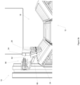
- FIGs 1- 3 there is shown a conveyor skirt system 10 in accordance with the present invention.
- the conveyor skirt system 10 is adapted to be used in association with a conventional conveyor 12.
- the conveyor 12 comprises a belt 14 that extends in a continuous loop around rollers and pulleys (not shown), in the known manner. As shown, the side edges of the belt 14 are canted upwardly by side support idler rollers 16, which are inclined as shown. An upper portion of the loop can be referred to as a transfer area 18. Bulk material (not shown) is loaded onto the transfer area 18 and is carried along the conveyor 12 by the belt 14.
- the conveyor 12 is typically supported on a framework 20.
- the conveyor skirt system 10 is positioned along the sides of the transfer area 18. The conveyor skirt system 10 acts to prevent or at least inhibit the migration of the bulk material outwardly from the transfer area 18.
- the conveyor skirt system 10 comprises a series of skirting panels 24.
- Each skirting panel 24 has a working face 25 directed towards the transfer area 18.
- each skirting panel 24 has a rear face 27.
- a wear liner 26 is fixed to the front face of each skirting panel 24.
- the wear liner 26 is mounted on each skirting panel 24 by fasteners 28.
- the series of skirting panels 24 are positioned such that a bottom edge 30 of each skirting panels 24 is close to the belt 14. Whilst some small bulk material may pass under the skirting panels 24, such material is prevented from escaping from the transfer area 18 by a rubber seal (not shown) positioned behind the rear face 27.
- Each skirting panel 24 is releasably fixed to a support member 33.
- the support member 33 is coupled to the framework 20.
- the support member 33 comprises a series of upper skirting panels 34.
- a wear liner 26 is fixed to the front face of each upper skirting panel 34.
- the support member could be any solid member capable of supporting the skirting panels 24.
- Such members include, for example, unitary beams.
- the skirting panels 24 do not necessarily need to depend from the support member 33.
- Alternative embodiments include the skirt panels 24 being fixed to the front of the support member 33.
- each upper skirting panel 34 is provided with side flanges 36 along the length of the side edges.
- the side flanges 36 are provided with apertures 38 that facilitate the location of bolts to fasten adjacent upper skirting panels 34 to one another.
- the rear face 27 of the skirting panels 24 are provided with an upper flange 40 along the length of the top edge.
- the upper flange spans the entire width of the skirting panels 24.
- a number of apertures 42 are provided through the upper flange 40 to facilitative the mounting of the skirting panels 24 to the support member 33.
- the upper skirting panels 34 are provided with a lower flange 44 along the periphery of the lower edge.
- the lower flanges 44 are provided with a number of apertures 46 to facilitate bolts 48 to fasten the skirting panels 24 to the upper skirting panels 34. It is envisaged that the embodiment shown in the Figures is particularly useful as it allows the skirting panels 24 to be unfastened from outside the transfer area 18. Advantageously, this allows the skirting panels 24 to be removed without requiring access to the inside of the transfer area 18.
- each skirting panel 24 may also be releasably fixed to its adjacent skirting panels 24. It is envisaged that each skirting panel 24 may be provided with side flanges along the length of the side edges. The side flanges could facilitate the location of bolts to fasten adjacent skirting panels 24 to one another. Alternatively, each skirting panel 24 could be provided with a mounting bracket that facilitates an engagement plate that could be fixed across the gap between two adjacent skirting panels 24.
- the conveyor skirt system 10 further comprises a rail assembly 56.
- the rail assembly 56 comprises a rigid body member 58 extending in a direction parallel to the direction of the conveyor 12.
- a rail track 60 is disposed along the rigid body member 58.
- the rail assembly 56 is positioned exterior to the skirting panels 24 and on the outside of the transfer area 18. In the embodiment shown in the Figures, the rail assembly 56 it fixed to the conveyor 12 framework 20.
- the trolley assembly 62 comprises rollers 64 that engage with the rail track 60.
- the engagement of the rollers 62 and the rail track 60 allows for the trolley assembly 62 to roll along the rail assembly 56.
- other means may be utilised to permit the sliding engagement of the trolley assembly 62 and the rail track 60.
- Such means include rack and pinion drives or slide pads.
- the trolley assembly 62 further comprises tube members 66 and engagement arms 68.
- the engagement arms 68 are tubular so as to permit the engagement arms 68 being received by the tube members 66.
- the trolley assembly 62 shown in the Figures comprises a pair of tube members 66 and engagement arms 68, it is envisaged that other configurations could also be utilised.
- a single tube member 66 and single engagement arm 68 could be utilised.
- two engagement arms 68 could be mounted on bracket which has a single tube for engaging with a tube member 66 extending therefrom.
- each tube member 66 and engagement arm 68 allows for the engagement arm 68 to extend from the tube member 66 towards the skirting panels 24. Conversely, once extended, the engagement arm 68 may retract back towards the rail assembly 56.
- the extension and retraction of the engagement arms 68 is actuated by an actuation mechanism, for example a winch mechanism (not shown) mounted on the rail assembly 56. It is envisaged that any actuation mechanism that permits the extension and retraction of the engagement arms 68 may be used. Examples of such mechanisms include hydraulic pistons and electric motor drive.
- Slide pins 74 are used to fix the tubes during extension and retraction of the extension tube 68. Whilst the embodiment shown in the Figures comprises a tube-in-tube design, it is envisaged that other configurations may be used. Such configurations includes two plate members slidingly engaged to one another. Alternatively, the engagement arms 68 could be provided in the form of plate members that extend from a solid body member.
- an upper mounting aperture 76 and a lower mounting aperture 78 are provided through the ends of each the engagement arm 68.
- the upper mounting aperture 76 and the lower mounting aperture 78 are offset in a horizontal direction, with the upper mounting aperture 76 set back from the lower mounting aperture 78.
- the upper mounting aperture 76 and a lower mounting aperture 78 are adapted to engage with the rear face 27 of a skirting panel 24.
- the rear face 27 of each skirting panel 24 is provided with mounting plates 80.
- Each mounting plate 80 has provided therethrough an upper aperture 82 and a lower aperture 84.
- the upper aperture 82 is adapted to engage with the upper mounting aperture 76 of the engagement arm 68.
- the lower aperture 84 is adapted to engage with the lower mounting aperture 78 of the engagement arm 68. It is envisaged that once the respective apertures are aligned, a locking pin (not shown) may be inserted to engage the skirting panel 24 to the trolley assembly 62. Given the offset positioning of the upper 76 and lower 78 mounting apertures, in order for the upper apertures to align, the skirting panel 24 must be rotated to a pivot position. It is envisaged that the pivot position assists in the removal of the skirting panels 24 from the conveyor 12.
- the rail assembly 56 further comprises a lateral rail track 80 orientated perpendicular to the direction of the rail track 58.
- the lateral rail track 80 is in communication with the rail track 58, such that the trolley assembly 62 may move from the rail track 58 to the lateral rail track 60.
- the lateral rail track 60 allows for the trolley assembly 62 and the skirting panel 24 to be moved in a lateral direction relative to the transfer area 18 to permit repair or replacement of the wear liners 26.
- Figures 3 (a) - (c) illustrate the use of the conveyor skirt system 10.
- a series of upper skirting panels 34 are fixed above a conveyor 12.
- a series of skirting panels 24 are fixed below the series of upper skirting panels 34.
- Each skirting panel 24 is fixed to its adjacent skirting panel 24.
- the conveyor 12 may operate normally, with the bulk material being retained in the transfer area 18 by the series of skirting panels 24.
- the wear liners 26 on the skirting panels 24 will need to be repaired or replaced.
- the trolley assembly 62 will be rolled along the rail assembly 56 to a position adjacent to a defective skirting panel 24.
- the winch mechanism is then actuated and the engagement arms 68 are extended towards the rear face 27 of the skirting panel 24.
- the engagement arms 68 are extended until the lower mounting aperture 78 is aligned with the lower aperture 84 of the mounting plate 80. Once aligned, a locking pin (not shown) may be inserted through the lower apertures, thereby engaging the trolley assembly 62 to the skirting panel 24. Once engaged, the weight of the skirting panel 24 is supported by the trolley assembly 62 and the skirting panel 24 may be unfastened from the upper skirting panel 34 and the adjacent skirting panels 24.
- the skirting panel 24 is then rotated to a pivot position, where the upper mounting aperture 76 is aligned with the upper aperture 82 of the mounting plate 80.
- a locking pin (not shown) may be inserted through the upper apertures, thereby retaining the lower skirt panel in the pivot position and further engaging the trolley assembly 62 to the skirting panels 24.
- the winch mechanism 70 is then actuated, preferably by an operator, to retract the engagement arms 68 and the skirting panel 24 towards the trolley assembly 62.
- the engagement arms 68 are retracted to a position where the skirting panel 24 is clear of the rest of the assembly, the trolley assembly 62 and the skirting panel 24 are free to roll along the rail assembly 56.
- simple and safe repair/replacement of the wear liner 26 can be undertaken.
- the entire repair/replacement process can be performed from outside the transfer area 18, reducing the risk of injuries to operators.
Landscapes
- Engineering & Computer Science (AREA)
- Mechanical Engineering (AREA)
- Rollers For Roller Conveyors For Transfer (AREA)
- Automatic Assembly (AREA)
- Connection Of Plates (AREA)
- Automobile Manufacture Line, Endless Track Vehicle, Trailer (AREA)
Description
- The present invention relates to a conveyor skirt system. More preferably, the conveyor skirt system of the present invention is intended to allow for the replacement of the conveyor skirt liner without the need for an operator inside the conveyor transfer area.
- The following discussion of the background art is intended to facilitate an understanding of the present invention only. The discussion is not an acknowledgement or admission that any of the material referred to is or was part of the common general knowledge as at the priority date of the application.
- In order to transfer bulk materials a conveyor system is often used. Such conveyor systems comprise a belt that extends in a continuous loop around rollers and pulleys. The upper portion of the loop can be referred to as a transfer area and the lower portion of the loop can be referred to as a return run. Bulk material is loaded onto the transfer area and is carried along by the conveyor system.
- As the bulk material is typically particulate in nature, it is also common to heap the bulk material near the centerline of the belt, while keeping such bulk material from spilling off the edges of the belt. To prevent such spillage, most conveyor systems comprise rigid skirts that are provided along each edge of the transfer area for purposes of redirecting stray bulk material and retaining such material on the belt.
- Because many types of bulk materials are abrasive, it is also common practice to attach wear liners to the skirts. In this manner, the wear liners prevent the direct contact of the skirts with the bulk material. Over time, the wear liners degrade from direct contact with the moving bulk material and periodically must be replaced.
- It is common practice to mount the wear liners on the face of the skirt that faces the centerline or center plane of the belt. Since the cross section of the belt is often trough-shaped, it is also common for the lower edge of a wear liner to be positioned lower than the lower edge of skirt so as to reduce the gap between the lower edge of the wear liner and the belt and to prevent wear to the backing plate of the skirt.
- Due to the fact that wear liners are mounted to the side of the skirt facing the center plane of the belt (the inward side), skirting replacement or maintenance is typically carried out by two work crews, one inside the chute/transfer area manipulating the liners in and out of place and the other crew outside chute/transfer area removing and replacing fasteners. Having an operator enter the chute/transfer area presents a significant safety risk.
- Whilst several proposed solutions have been developed that seek to limit the amount of interaction required from inside the transfer area, there is often still a need for an operator to place their hands inside the transfer area, albeit from the outside, to replace components. This leads to difficulties in positioning the wear liners accurately, and presents a risk of injury.
- United States Patent Application
US2008277245A1 discloses an apparatus for replacing wear liner plates from the side of a conveyor. The apparatus includes at least one wear liner plate which is removably mounted to the apparatus so as to allow the at least one liner plate to be detached from the exterior of the conveyor. To remove the wear liner plate for replacement, it is unfastened from the apparatus and rotated into a removal position which allows an operator to remove the wear liner plate. The apparatus further includes a support means which supports the wear liner plate when it is unfastened from the apparatus.US2008277245A1 further discloses a method for replacing a wear liner on a skirting panel of a conveyor. - In accordance with the present invention, there is provided a conveyor skirt system, the system comprising:
- a support member fixed relative to the conveyor;
- a series of skirting panels releasably fixed to the support member;
- a rail assembly positioned outside the conveyor, extending in a direction substantially parallel to the direction of the conveyor; and
- a trolley assembly mounted on the rail assembly, the trolley assembly being adapted to engage and support one or more of the skirting panels.
- Preferably, each skirting panel has a wear liner attached thereto.
- Preferably, the arrangement of the trolley assembly and the rail assembly allows the trolley assembly to move along the length of the rail assembly in either direction.
- It is envisaged that the conveyor skirt system of the present invention will allow for the simple replacement of the skirting panels. Preferably, the trolley assembly is adapted to move along the rail assembly to a position adjacent to the skirting panel to be replaced. Once in position, the trolley assembly will engage and support the skirting panel, allowing the skirting panel to be unfastened from the support member. Once the skirting panel is mounted and correctly located on the trolley assembly, it can then be moved along the rail assembly, clear of the conveyor. Once clear of the conveyor, the skirting panel may be repaired or replaced outside of the confines of the conveyor. Preferably, the support member is coupled to the conveyor framework.
- In one form of the present invention, the rail assembly comprises one or more rail tracks. Preferably, the one or more rail tracks are mounted on a rigid body member.
- In one form of the present invention, the trolley assembly comprises a rail assembly engaging portion and a skirting panel engaging portion. Preferably, the rail assembly engaging portion is adapted to engage and move along the rail assembly. Preferably, the skirting panel engaging portion is adapted to engage a skirting panel.
- Preferably, the rail assembly engaging portion comprises one or more rollers adapted to roll along the rail assembly.
- In one form of the present invention, the skirting panel engaging portion comprises one or more engagement arms. Preferably, the one or more engagement arms are adapted to engage a skirting panel. More preferably, the one or more engagement arms are adapted to extend and retract.
- In one form of the present invention, the skirting panel engaging portion comprises one or more body members. More preferably, the or each engagement arm is adapted to extend and retract with respect to at least one body member.
- In one form of the present invention, the body member comprises a tube member. Preferably, each engagement arm is in the form of a tube. More preferably, each engagement arm is slidingly engaged with a tube member. Still preferably, the engagement arm is able to telescope inside the tube member. It is envisaged that the engagement between the tube member and the engagement arm, allows the engagement arm to be extended and retracted.
- Preferably, the trolley assembly further comprises an actuation mechanism. More preferably, the extension and retraction of the engagement arm is actuated by the actuation mechanism. Still preferably, the actuation mechanism is a winch mechanism.
- In one form of the present invention, where the trolley assembly comprises tube members and engagement tubes, actuation of the winch mechanism extends and retracts the engagement tube relative to the tube member.
- In a preferred form of the present invention, the trolley assembly comprises a pair of engagement arms. Preferably, each of the engagement arms are adapted to engage with a skirting panel at different positions.
- In one form of the present invention, each skirting panel has a working face and a rear face. Preferably, the wear liner is attached to the working face. More preferably, the trolley assembly engages with the rear face.
- In one form of the present invention, each skirting panel is provided with one or more attachment means. Preferably, the rear face of each skirting panel is provided with one or more attachment means. More preferably, each attachment means is adapted to be engaged by the trolley assembly. Still preferably, where the trolley assembly comprises one or more engagement arms, each attachment means is adapted to be engaged by an engagement arm.
- In one form of the present invention, the engagement of the trolley assembly and the attachment means is by way of a lock pin mechanism. Preferably, the lock pin mechanism will comprise a pin that will pass through apertures provided in both the trolley assembly and the attachment means.
- In one form of the present invention, each attachment means comprises a mounting aperture adapted for engagement with the trolley assembly. More preferably, the mounting aperture is adapted for engagement with the one or more engagement arms. It is envisaged that each engagement arm can be affixed to the mounting apertures, thereby fastening the lower skirt panel to the trolley assembly.
- In one form of the present invention, the attachment means comprises a mounting plate extending from the rear face of the skirting panel. More preferably, each mounting plate has provided therethrough at least mounting aperture. Still preferably, the mounting plate has two mounting apertures, being an upper mounting aperture and a lower mounting aperture.
- Preferably, each engagement arm has provided at least one mounting aperture provided therethrough, the at least one mounting aperture adapted to engage with the rear face of each skirting panel. More preferably, the mounting plate has two mounting apertures, being an upper mounting aperture and a lower mounting aperture. Still preferably, the upper mounting aperture and the lower mounting aperture are offset in a horizontal direction.
- Preferably, where the rear face of each skirting panel is provided with one or more attachment means, the at least one mounting aperture is adapted to engage with the one or more attachment means. More preferably, the engagement of the attachment means and the mounting aperture is by way of a lock pin mechanism.
- In a preferred form of the present invention, the rear face of the each skirting panel is provided with one or more attachment means, each attachment means having an upper aperture and a lower aperture. Furthermore, each engagement arm is provided with an upper mounting aperture and a lower mounting aperture. Preferably, the upper aperture of the attachment means cooperates with the upper mounting aperture of the engagement arm. Likewise, the lower aperture of the attachment means cooperates with the lower mounting aperture of the engagement arm. Preferably, the engagement of the apertures is by way of respective upper and lower lock pin mechanisms.
- As discussed above, each skirting panel is releasably fixed to the support member. In one form of the present invention, the skirt panels depend from the support member.
- In one form of the present invention, an upper flange is provided on the rear face of each skirting panel. Preferably, each skirting panel is releasably fixed to the support member by way of the upper flange. More preferably, a lower flange is provided on the support member to co-operate with the upper flange of the skirting panel. Still preferably, one or more fastening means are provided through the lower flange on the support member and the upper flange of the skirting panel. Still preferably, the one or more fastening means are nuts and bolts.
- In one form of the present invention, each skirting panel is releasably fixed to the adjacent skirting panel in the series. Preferably, opposed lateral flanges are provided on the rear face of each skirting panel. More preferably, one or more fastening means are provided through each lateral flange and the lateral flange on the adjacent skirting panel. Still preferably, the one or more fastening means are nuts and bolts.
- In one form of the present invention, the support member comprises a series of upper skirting panels releasably fixed to each other. Preferably, opposed lateral flanges are provided on the rear face of each upper skirting panel. More preferably, one or more fastening means are provided through each lateral flange and the lateral flange on the adjacent upper skirting panel. Still preferably, the one or more fastening means are nuts and bolts.
- In one form of the present invention, one or more wear liners are provided on the support member. Alternatively, where the support member comprises a series of upper skirting panels, a wear liner is fastened to each upper skirting panel.
- In one form of the present invention, the rail assembly further comprises a lateral rail track orientated perpendicular to the direction of the rail track. Preferably, the lateral rail track is in communication with the rail track, such that the trolley assembly may move from the rail track to the lateral rail track. It is envisaged that the lateral rail track allows for the trolley assembly and the skirting panel to be moved in a lateral direction relative to the conveyor.
- In accordance with a further aspect of the present invention, there is provided a method for using to conveyor skirt system as described above to replace a wear liner on a skirting panel of a conveyor.
- In accordance with a further aspect of the present invention, there is provided a method for replacing a wear liner on a skirting panel of a conveyor, the method comprising the step of:
- positioning a trolley assembly mounted on a rail assembly adjacent to the skirting panel with the wear liner to be replaced fastened thereto;
- engaging the skirting panel with the trolley assembly and unfastening the skirting panel from the conveyor;
- moving the trolley assembly and the skirting panel along the rail assembly to a position clear of the conveyor;
- replacing the skirting panel and/or the wear liner;
- moving the trolley assembly and the skirting panel along the rail assembly to a position suitable for mounting; and
- fastening to the skirting panel to the conveyor.
- Preferably, the method for replacing a wear liner on a skirting panel of a conveyor utilises the conveyor skirt system as described above.
- Further features of the present invention are more fully described in the following description of several non-limiting embodiments thereof. This description is included solely for the purposes of exemplifying the present invention. It should not be understood as a restriction on the broad summary, disclosure or description of the invention as set out above. The description will be made with reference to the accompanying drawings in which:
-
Figure 1 is a front view of the conveyor skirt system of the present invention; -
Figure 2 is a rear perspective view of the conveyor skirt system ofFigure 1 ; and -
Figures 3 (a) - (c) show a series of reverse perspective views of the conveyor skirt of the present invention demonstrating the removal of a skirting panel. - Throughout this specification, unless the context requires otherwise, the word "comprise" or variations such as "comprises" or "comprising", will be understood to imply the inclusion of a stated integer or group of integers but not the exclusion of any other integer or group of integers.
- In
Figures 1- 3 , there is shown aconveyor skirt system 10 in accordance with the present invention. Theconveyor skirt system 10 is adapted to be used in association with aconventional conveyor 12. Theconveyor 12 comprises abelt 14 that extends in a continuous loop around rollers and pulleys (not shown), in the known manner. As shown, the side edges of thebelt 14 are canted upwardly by side supportidler rollers 16, which are inclined as shown. An upper portion of the loop can be referred to as atransfer area 18. Bulk material (not shown) is loaded onto thetransfer area 18 and is carried along theconveyor 12 by thebelt 14. Theconveyor 12 is typically supported on aframework 20. - As the bulk material is typically particulate in nature, it is necessary to ensure that the bulk material does not spill from the edge of the
belt 14. To prevent such spillage, theconveyor skirt system 10 is positioned along the sides of thetransfer area 18. Theconveyor skirt system 10 acts to prevent or at least inhibit the migration of the bulk material outwardly from thetransfer area 18. - The
conveyor skirt system 10 comprises a series of skirtingpanels 24. Each skirtingpanel 24 has a workingface 25 directed towards thetransfer area 18. Similarly, each skirtingpanel 24 has arear face 27. Awear liner 26 is fixed to the front face of each skirtingpanel 24. As shown inFigure 2 , thewear liner 26 is mounted on each skirtingpanel 24 by fasteners 28. As shown in the Figures, the series of skirtingpanels 24 are positioned such that a bottom edge 30 of each skirtingpanels 24 is close to thebelt 14. Whilst some small bulk material may pass under the skirtingpanels 24, such material is prevented from escaping from thetransfer area 18 by a rubber seal (not shown) positioned behind therear face 27. - Each skirting
panel 24 is releasably fixed to asupport member 33. Thesupport member 33 is coupled to theframework 20. In the embodiment shown in the Figures, thesupport member 33 comprises a series ofupper skirting panels 34. Awear liner 26 is fixed to the front face of eachupper skirting panel 34. It is envisaged that the support member could be any solid member capable of supporting the skirtingpanels 24. Such members include, for example, unitary beams. Furthermore, it is envisaged that the skirtingpanels 24 do not necessarily need to depend from thesupport member 33. Alternative embodiments include theskirt panels 24 being fixed to the front of thesupport member 33. - In the embodiment shown in the Figures, each
upper skirting panel 34 is provided with side flanges 36 along the length of the side edges. The side flanges 36 are provided with apertures 38 that facilitate the location of bolts to fasten adjacentupper skirting panels 34 to one another. - The
rear face 27 of the skirtingpanels 24 are provided with anupper flange 40 along the length of the top edge. In the embodiment shown in the Figures, the upper flange spans the entire width of the skirtingpanels 24. A number of apertures 42 are provided through theupper flange 40 to facilitative the mounting of the skirtingpanels 24 to thesupport member 33. In the embodiment shown in the Figures, theupper skirting panels 34 are provided with alower flange 44 along the periphery of the lower edge. Thelower flanges 44 are provided with a number of apertures 46 to facilitate bolts 48 to fasten theskirting panels 24 to theupper skirting panels 34. It is envisaged that the embodiment shown in the Figures is particularly useful as it allows the skirtingpanels 24 to be unfastened from outside thetransfer area 18. Advantageously, this allows the skirtingpanels 24 to be removed without requiring access to the inside of thetransfer area 18. - Whilst not shown in the Figures, each skirting
panel 24 may also be releasably fixed to itsadjacent skirting panels 24. It is envisaged that each skirtingpanel 24 may be provided with side flanges along the length of the side edges. The side flanges could facilitate the location of bolts to fastenadjacent skirting panels 24 to one another. Alternatively, each skirtingpanel 24 could be provided with a mounting bracket that facilitates an engagement plate that could be fixed across the gap between twoadjacent skirting panels 24. - The
conveyor skirt system 10 further comprises arail assembly 56. Therail assembly 56 comprises arigid body member 58 extending in a direction parallel to the direction of theconveyor 12. Arail track 60 is disposed along therigid body member 58. Therail assembly 56 is positioned exterior to the skirtingpanels 24 and on the outside of thetransfer area 18. In the embodiment shown in the Figures, therail assembly 56 it fixed to theconveyor 12framework 20. - Mounted on the
rail assembly 56 is atrolley assembly 62. Thetrolley assembly 62 comprisesrollers 64 that engage with therail track 60. The engagement of therollers 62 and therail track 60 allows for thetrolley assembly 62 to roll along therail assembly 56. It is envisaged that other means may be utilised to permit the sliding engagement of thetrolley assembly 62 and therail track 60. Such means include rack and pinion drives or slide pads. - In the embodiment shown in the Figures, the
trolley assembly 62 further comprisestube members 66 andengagement arms 68. As seen in the Figures, theengagement arms 68 are tubular so as to permit theengagement arms 68 being received by thetube members 66. Whilst thetrolley assembly 62 shown in the Figures comprises a pair oftube members 66 andengagement arms 68, it is envisaged that other configurations could also be utilised. For example, asingle tube member 66 andsingle engagement arm 68 could be utilised. Alternatively, twoengagement arms 68 could be mounted on bracket which has a single tube for engaging with atube member 66 extending therefrom. - The arrangement of each
tube member 66 andengagement arm 68 allows for theengagement arm 68 to extend from thetube member 66 towards the skirtingpanels 24. Conversely, once extended, theengagement arm 68 may retract back towards therail assembly 56. The extension and retraction of theengagement arms 68 is actuated by an actuation mechanism, for example a winch mechanism (not shown) mounted on therail assembly 56. It is envisaged that any actuation mechanism that permits the extension and retraction of theengagement arms 68 may be used. Examples of such mechanisms include hydraulic pistons and electric motor drive. Slide pins 74 are used to fix the tubes during extension and retraction of theextension tube 68. Whilst the embodiment shown in the Figures comprises a tube-in-tube design, it is envisaged that other configurations may be used. Such configurations includes two plate members slidingly engaged to one another. Alternatively, theengagement arms 68 could be provided in the form of plate members that extend from a solid body member. - As best seen in
Figure 2 , an upper mountingaperture 76 and a lower mountingaperture 78 are provided through the ends of each theengagement arm 68. The upper mountingaperture 76 and the lower mountingaperture 78 are offset in a horizontal direction, with the upper mountingaperture 76 set back from the lower mountingaperture 78. The upper mountingaperture 76 and a lower mountingaperture 78 are adapted to engage with therear face 27 of askirting panel 24. Therear face 27 of each skirtingpanel 24 is provided with mountingplates 80. Each mountingplate 80 has provided therethrough anupper aperture 82 and alower aperture 84. Theupper aperture 82 is adapted to engage with the upper mountingaperture 76 of theengagement arm 68. Similarly, thelower aperture 84 is adapted to engage with the lower mountingaperture 78 of theengagement arm 68. It is envisaged that once the respective apertures are aligned, a locking pin (not shown) may be inserted to engage theskirting panel 24 to thetrolley assembly 62. Given the offset positioning of the upper 76 and lower 78 mounting apertures, in order for the upper apertures to align, the skirtingpanel 24 must be rotated to a pivot position. It is envisaged that the pivot position assists in the removal of the skirtingpanels 24 from theconveyor 12. - Whilst the embodiment shown in the Figures utilises a lock pin mechanism to fasten the
skirt panel 24 to theengagement arms 68, it is envisaged that other engagement mechanisms may be used. Such engagement mechanisms include vice grips or screw fasteners. - The
rail assembly 56 further comprises alateral rail track 80 orientated perpendicular to the direction of therail track 58. Preferably, thelateral rail track 80 is in communication with therail track 58, such that thetrolley assembly 62 may move from therail track 58 to thelateral rail track 60. In such a manner, thelateral rail track 60 allows for thetrolley assembly 62 and theskirting panel 24 to be moved in a lateral direction relative to thetransfer area 18 to permit repair or replacement of thewear liners 26. -
Figures 3 (a) - (c) illustrate the use of theconveyor skirt system 10. As shown inFigure 3(a) , a series ofupper skirting panels 34 are fixed above aconveyor 12. A series of skirtingpanels 24 are fixed below the series ofupper skirting panels 34. Each skirtingpanel 24 is fixed to itsadjacent skirting panel 24. Theconveyor 12 may operate normally, with the bulk material being retained in thetransfer area 18 by the series of skirtingpanels 24. Eventually, thewear liners 26 on the skirtingpanels 24 will need to be repaired or replaced. Thetrolley assembly 62 will be rolled along therail assembly 56 to a position adjacent to adefective skirting panel 24. The winch mechanism is then actuated and theengagement arms 68 are extended towards therear face 27 of the skirtingpanel 24. Theengagement arms 68 are extended until the lower mountingaperture 78 is aligned with thelower aperture 84 of the mountingplate 80. Once aligned, a locking pin (not shown) may be inserted through the lower apertures, thereby engaging thetrolley assembly 62 to theskirting panel 24. Once engaged, the weight of the skirtingpanel 24 is supported by thetrolley assembly 62 and theskirting panel 24 may be unfastened from theupper skirting panel 34 and theadjacent skirting panels 24. - As shown in
Figure 3(b) , the skirtingpanel 24 is then rotated to a pivot position, where the upper mountingaperture 76 is aligned with theupper aperture 82 of the mountingplate 80. Once aligned, a locking pin (not shown) may be inserted through the upper apertures, thereby retaining the lower skirt panel in the pivot position and further engaging thetrolley assembly 62 to the skirtingpanels 24. - As shown in
Figure 3(c) , the winch mechanism 70 is then actuated, preferably by an operator, to retract theengagement arms 68 and theskirting panel 24 towards thetrolley assembly 62. Once theengagement arms 68 are retracted to a position where the skirtingpanel 24 is clear of the rest of the assembly, thetrolley assembly 62 and theskirting panel 24 are free to roll along therail assembly 56. Advantageously, once thetrolley assembly 62 is clear of theconveyor 12, simple and safe repair/replacement of thewear liner 26 can be undertaken. Furthermore, the entire repair/replacement process can be performed from outside thetransfer area 18, reducing the risk of injuries to operators.
Claims (15)
- A conveyor skirt system (10), the system comprising:a support member (33) fixed relative to the conveyor; anda series of skirting panels (24) releasably fixed to the support member (33),characterised in that the system further comprisesa rail assembly (56) positioned outside the conveyor, extending in a direction substantially parallel to the direction of the conveyor; anda trolley assembly (62) mounted on the rail assembly (56), the trolley assembly (62) being adapted to engage and support one or more of the skirting panels (24).
- A conveyor skirt system (10) according to claim 1, wherein each skirting panel (24) has a wear liner (26) attached thereto.
- A conveyor skirt system (10) according to claim 1 or 2, wherein the arrangement of the trolley assembly (62) and the rail assembly (56) allows the trolley assembly (62) to run along the length of the rail assembly (56) in either direction.
- A conveyor skirt system (10) according to any one of preceding claims, wherein the rail assembly (56) comprises one or more rail tracks (60).
- A conveyor skirt system (10) according to any one of preceding claims, wherein the trolley assembly (62) comprises a rail assembly engaging portion and a skirting panel engaging portion.
- A conveyor skirt system (10) according to claim 5, wherein the rail assembly (56) engaging portion is adapted to engage and move along the rail assembly (56).
- A conveyor skirt system (10) according to any one of claims 5 or 6, wherein the skirting panel (24) engaging portion comprises one or more engagement arms (68) adapted to engage a skirting panel (24).
- A conveyor skirt system (10) according to claim 7, wherein the one or more engagement arms (68) are adapted to extend and retract.
- A conveyor skirt system (10) according to any one of preceding claims, wherein each skirting panel (24) is provided with one or more attachment means adapted to be engaged by the trolley assembly (62).
- A conveyor skirt system (10) according to claim 9, wherein each attachment means comprises a mounting aperture (82, 84) adapted for engagement with the trolley assembly (62).
- A conveyor skirt system (10) according to claim 10, wherein the mounting aperture (82, 84) is adapted for engagement with the one or more engagement arms (68).
- A conveyor skirt system (10) according to any one of preceding claims, wherein the skirt panels depend from the support member (33).
- A conveyor skirt system (10) according to any one of preceding claims, wherein each skirting panel (24) is releasably fixed to the adjacent skirting panel (24).
- A conveyor skirt system (10) according to any one of preceding claims, wherein the rail assembly (56) further comprises a lateral rail track (80) orientated perpendicular to the direction of the rail track
- A method for replacing a wear liner on a skirting panel (24) of a conveyor, the method comprising the step of:positioning a trolley assembly (62) mounted on a rail assembly (56) adjacent to the skirting panel (24) with the wear liner (26) to be replaced fastened thereto;engaging the skirting panel (24) with the trolley assembly (62) and unfastening the skirting panel (24) from the conveyor;moving the trolley assembly (62) and the skirting panel (24) along the rail assembly (56) to a position clear of the conveyor;replacing the skirting panel (24) and/or the wear liner (26);moving the trolley assembly (62) and the skirting panel (24) along the rail assembly (56) to a position suitable for mounting; andfastening to the skirting panel (24) to the conveyor.
Applications Claiming Priority (2)
| Application Number | Priority Date | Filing Date | Title |
|---|---|---|---|
| AU2017903475A AU2017903475A0 (en) | 2017-08-28 | Conveyor Skirt System | |
| PCT/AU2018/050917 WO2019040980A1 (en) | 2017-08-28 | 2018-08-28 | Conveyor skirt system |
Publications (4)
| Publication Number | Publication Date |
|---|---|
| EP3676201A1 EP3676201A1 (en) | 2020-07-08 |
| EP3676201A4 EP3676201A4 (en) | 2021-06-16 |
| EP3676201C0 EP3676201C0 (en) | 2024-02-21 |
| EP3676201B1 true EP3676201B1 (en) | 2024-02-21 |
Family
ID=65524595
Family Applications (1)
| Application Number | Title | Priority Date | Filing Date |
|---|---|---|---|
| EP18849502.2A Active EP3676201B1 (en) | 2017-08-28 | 2018-08-28 | Conveyor skirt system |
Country Status (7)
| Country | Link |
|---|---|
| US (1) | US10934097B2 (en) |
| EP (1) | EP3676201B1 (en) |
| AU (1) | AU2018326290B2 (en) |
| CA (1) | CA3073968A1 (en) |
| CL (1) | CL2020000494A1 (en) |
| WO (1) | WO2019040980A1 (en) |
| ZA (1) | ZA202001932B (en) |
Family Cites Families (6)
| Publication number | Priority date | Publication date | Assignee | Title |
|---|---|---|---|---|
| US4789056A (en) * | 1987-02-03 | 1988-12-06 | Solidur Plastics Co. | Slider bed conveyor apparatus and associated method |
| US5267642A (en) * | 1992-10-15 | 1993-12-07 | Richwood Industries, Inc. | Skirt board and impact saddle assembly for conveyor belts |
| US6763935B2 (en) * | 2002-08-16 | 2004-07-20 | Nelson Williams Linings, Inc. | Pivotable conveyor skirt board assembly |
| US7789220B2 (en) * | 2005-11-11 | 2010-09-07 | Wear Applications & Management Services Pty Ltd | Liner plate replacement |
| US7571802B2 (en) * | 2007-07-26 | 2009-08-11 | Martin Engineering Company | Conveyor belt skirt assembly |
| US8006830B2 (en) * | 2008-09-19 | 2011-08-30 | Martin Engineering Company | Exteriorly mounted wear liner for bulk material conveyor belt systems |
-
2018
- 2018-08-28 AU AU2018326290A patent/AU2018326290B2/en active Active
- 2018-08-28 EP EP18849502.2A patent/EP3676201B1/en active Active
- 2018-08-28 WO PCT/AU2018/050917 patent/WO2019040980A1/en not_active Ceased
- 2018-08-28 CA CA3073968A patent/CA3073968A1/en active Pending
- 2018-08-28 US US16/643,020 patent/US10934097B2/en active Active
-
2020
- 2020-02-28 CL CL2020000494A patent/CL2020000494A1/en unknown
- 2020-03-24 ZA ZA2020/01932A patent/ZA202001932B/en unknown
Also Published As
| Publication number | Publication date |
|---|---|
| ZA202001932B (en) | 2021-08-25 |
| US10934097B2 (en) | 2021-03-02 |
| EP3676201A1 (en) | 2020-07-08 |
| AU2018326290A1 (en) | 2020-04-16 |
| CL2020000494A1 (en) | 2020-09-11 |
| EP3676201A4 (en) | 2021-06-16 |
| EP3676201C0 (en) | 2024-02-21 |
| CA3073968A1 (en) | 2019-03-07 |
| WO2019040980A1 (en) | 2019-03-07 |
| BR112020004139A2 (en) | 2020-09-01 |
| AU2018326290B2 (en) | 2024-02-08 |
| US20200198898A1 (en) | 2020-06-25 |
Similar Documents
| Publication | Publication Date | Title |
|---|---|---|
| US8387781B2 (en) | Conveyor roller servicing apparatus | |
| TWI501911B (en) | Bulk material conveyor belt systems and methods for replacing and moving a wear liner | |
| EP2646284B1 (en) | Attachment method | |
| US3800965A (en) | Ladle skimming mechanism | |
| AU2018326290B2 (en) | Conveyor skirt system | |
| US8540071B2 (en) | Conveyor roller support arrangement | |
| CN107855685B (en) | A transfer mechanism for flexible assembly system of automobile body-in-white welding | |
| AU2019236704B2 (en) | Conveyor skirt liner system | |
| DE102014010556B4 (en) | Drive car for a transport device and transport system | |
| AU2016101634A4 (en) | An apparatus and a method for lifting a conveyor belt | |
| CN209579385U (en) | Carrier roller replacing tool | |
| US20250304377A1 (en) | Conveyor skirting removal system | |
| BR112020004139B1 (en) | CONVEYOR SKIRT SYSTEM AND METHOD FOR REPLACING A WEAR LINING ON A CONVEYOR SKIRT PANEL | |
| DE2748542C3 (en) | Bellless loading device for shaft furnaces, especially blast furnaces | |
| AU2014200188A1 (en) | Improvements to conveyor loading equipment and installations | |
| US6827200B1 (en) | Multi-speed variable spacing conveyor system | |
| AU2021421335A1 (en) | Sealing arrangement for a conveyor | |
| CN120677113A (en) | Mechanical fastening structure assembly for curved belt conveyor and method of use thereof | |
| AU2017216448A1 (en) | An apparatus and a method for lifting a conveyor belt | |
| KR20150120006A (en) | Apparatus transferring steel plate with variable width | |
| RU240308U1 (en) | RAILWAY CAR | |
| CN108341344B (en) | Lifting mechanism and container having the same | |
| CN222973527U (en) | For military use track dismantles frock | |
| CN211617725U (en) | Vehicle body protection device | |
| EP0328927B1 (en) | Loading bridge for ramps |
Legal Events
| Date | Code | Title | Description |
|---|---|---|---|
| STAA | Information on the status of an ep patent application or granted ep patent |
Free format text: STATUS: THE INTERNATIONAL PUBLICATION HAS BEEN MADE |
|
| PUAI | Public reference made under article 153(3) epc to a published international application that has entered the european phase |
Free format text: ORIGINAL CODE: 0009012 |
|
| STAA | Information on the status of an ep patent application or granted ep patent |
Free format text: STATUS: REQUEST FOR EXAMINATION WAS MADE |
|
| 17P | Request for examination filed |
Effective date: 20200324 |
|
| AK | Designated contracting states |
Kind code of ref document: A1 Designated state(s): AL AT BE BG CH CY CZ DE DK EE ES FI FR GB GR HR HU IE IS IT LI LT LU LV MC MK MT NL NO PL PT RO RS SE SI SK SM TR |
|
| AX | Request for extension of the european patent |
Extension state: BA ME |
|
| DAV | Request for validation of the european patent (deleted) | ||
| DAX | Request for extension of the european patent (deleted) | ||
| A4 | Supplementary search report drawn up and despatched |
Effective date: 20210514 |
|
| RIC1 | Information provided on ipc code assigned before grant |
Ipc: B65G 21/20 20060101AFI20210508BHEP Ipc: E21F 13/08 20060101ALI20210508BHEP Ipc: E21D 9/12 20060101ALI20210508BHEP |
|
| GRAP | Despatch of communication of intention to grant a patent |
Free format text: ORIGINAL CODE: EPIDOSNIGR1 |
|
| STAA | Information on the status of an ep patent application or granted ep patent |
Free format text: STATUS: GRANT OF PATENT IS INTENDED |
|
| INTG | Intention to grant announced |
Effective date: 20231016 |
|
| GRAS | Grant fee paid |
Free format text: ORIGINAL CODE: EPIDOSNIGR3 |
|
| GRAA | (expected) grant |
Free format text: ORIGINAL CODE: 0009210 |
|
| STAA | Information on the status of an ep patent application or granted ep patent |
Free format text: STATUS: THE PATENT HAS BEEN GRANTED |
|
| AK | Designated contracting states |
Kind code of ref document: B1 Designated state(s): AL AT BE BG CH CY CZ DE DK EE ES FI FR GB GR HR HU IE IS IT LI LT LU LV MC MK MT NL NO PL PT RO RS SE SI SK SM TR |
|
| REG | Reference to a national code |
Ref country code: GB Ref legal event code: FG4D |
|
| REG | Reference to a national code |
Ref country code: CH Ref legal event code: EP |
|
| REG | Reference to a national code |
Ref country code: DE Ref legal event code: R096 Ref document number: 602018065649 Country of ref document: DE |
|
| REG | Reference to a national code |
Ref country code: IE Ref legal event code: FG4D |
|
| U01 | Request for unitary effect filed |
Effective date: 20240320 |
|
| U07 | Unitary effect registered |
Designated state(s): AT BE BG DE DK EE FI FR IT LT LU LV MT NL PT SE SI Effective date: 20240328 |
|
| PG25 | Lapsed in a contracting state [announced via postgrant information from national office to epo] |
Ref country code: IS Free format text: LAPSE BECAUSE OF FAILURE TO SUBMIT A TRANSLATION OF THE DESCRIPTION OR TO PAY THE FEE WITHIN THE PRESCRIBED TIME-LIMIT Effective date: 20240621 |
|
| PG25 | Lapsed in a contracting state [announced via postgrant information from national office to epo] |
Ref country code: GR Free format text: LAPSE BECAUSE OF FAILURE TO SUBMIT A TRANSLATION OF THE DESCRIPTION OR TO PAY THE FEE WITHIN THE PRESCRIBED TIME-LIMIT Effective date: 20240522 |
|
| PG25 | Lapsed in a contracting state [announced via postgrant information from national office to epo] |
Ref country code: RS Free format text: LAPSE BECAUSE OF FAILURE TO SUBMIT A TRANSLATION OF THE DESCRIPTION OR TO PAY THE FEE WITHIN THE PRESCRIBED TIME-LIMIT Effective date: 20240521 Ref country code: HR Free format text: LAPSE BECAUSE OF FAILURE TO SUBMIT A TRANSLATION OF THE DESCRIPTION OR TO PAY THE FEE WITHIN THE PRESCRIBED TIME-LIMIT Effective date: 20240221 |
|
| PG25 | Lapsed in a contracting state [announced via postgrant information from national office to epo] |
Ref country code: ES Free format text: LAPSE BECAUSE OF FAILURE TO SUBMIT A TRANSLATION OF THE DESCRIPTION OR TO PAY THE FEE WITHIN THE PRESCRIBED TIME-LIMIT Effective date: 20240221 |
|
| PG25 | Lapsed in a contracting state [announced via postgrant information from national office to epo] |
Ref country code: RS Free format text: LAPSE BECAUSE OF FAILURE TO SUBMIT A TRANSLATION OF THE DESCRIPTION OR TO PAY THE FEE WITHIN THE PRESCRIBED TIME-LIMIT Effective date: 20240521 Ref country code: NO Free format text: LAPSE BECAUSE OF FAILURE TO SUBMIT A TRANSLATION OF THE DESCRIPTION OR TO PAY THE FEE WITHIN THE PRESCRIBED TIME-LIMIT Effective date: 20240521 Ref country code: IS Free format text: LAPSE BECAUSE OF FAILURE TO SUBMIT A TRANSLATION OF THE DESCRIPTION OR TO PAY THE FEE WITHIN THE PRESCRIBED TIME-LIMIT Effective date: 20240621 Ref country code: HR Free format text: LAPSE BECAUSE OF FAILURE TO SUBMIT A TRANSLATION OF THE DESCRIPTION OR TO PAY THE FEE WITHIN THE PRESCRIBED TIME-LIMIT Effective date: 20240221 Ref country code: GR Free format text: LAPSE BECAUSE OF FAILURE TO SUBMIT A TRANSLATION OF THE DESCRIPTION OR TO PAY THE FEE WITHIN THE PRESCRIBED TIME-LIMIT Effective date: 20240522 Ref country code: ES Free format text: LAPSE BECAUSE OF FAILURE TO SUBMIT A TRANSLATION OF THE DESCRIPTION OR TO PAY THE FEE WITHIN THE PRESCRIBED TIME-LIMIT Effective date: 20240221 |
|
| PG25 | Lapsed in a contracting state [announced via postgrant information from national office to epo] |
Ref country code: PL Free format text: LAPSE BECAUSE OF FAILURE TO SUBMIT A TRANSLATION OF THE DESCRIPTION OR TO PAY THE FEE WITHIN THE PRESCRIBED TIME-LIMIT Effective date: 20240221 |
|
| PG25 | Lapsed in a contracting state [announced via postgrant information from national office to epo] |
Ref country code: PL Free format text: LAPSE BECAUSE OF FAILURE TO SUBMIT A TRANSLATION OF THE DESCRIPTION OR TO PAY THE FEE WITHIN THE PRESCRIBED TIME-LIMIT Effective date: 20240221 |
|
| PG25 | Lapsed in a contracting state [announced via postgrant information from national office to epo] |
Ref country code: SM Free format text: LAPSE BECAUSE OF FAILURE TO SUBMIT A TRANSLATION OF THE DESCRIPTION OR TO PAY THE FEE WITHIN THE PRESCRIBED TIME-LIMIT Effective date: 20240221 |
|
| PG25 | Lapsed in a contracting state [announced via postgrant information from national office to epo] |
Ref country code: CZ Free format text: LAPSE BECAUSE OF FAILURE TO SUBMIT A TRANSLATION OF THE DESCRIPTION OR TO PAY THE FEE WITHIN THE PRESCRIBED TIME-LIMIT Effective date: 20240221 |
|
| PG25 | Lapsed in a contracting state [announced via postgrant information from national office to epo] |
Ref country code: SK Free format text: LAPSE BECAUSE OF FAILURE TO SUBMIT A TRANSLATION OF THE DESCRIPTION OR TO PAY THE FEE WITHIN THE PRESCRIBED TIME-LIMIT Effective date: 20240221 |
|
| U21 | Renewal fee for the european patent with unitary effect paid with additional fee |
Year of fee payment: 7 Effective date: 20240925 |
|
| PG25 | Lapsed in a contracting state [announced via postgrant information from national office to epo] |
Ref country code: SM Free format text: LAPSE BECAUSE OF FAILURE TO SUBMIT A TRANSLATION OF THE DESCRIPTION OR TO PAY THE FEE WITHIN THE PRESCRIBED TIME-LIMIT Effective date: 20240221 Ref country code: SK Free format text: LAPSE BECAUSE OF FAILURE TO SUBMIT A TRANSLATION OF THE DESCRIPTION OR TO PAY THE FEE WITHIN THE PRESCRIBED TIME-LIMIT Effective date: 20240221 Ref country code: RO Free format text: LAPSE BECAUSE OF FAILURE TO SUBMIT A TRANSLATION OF THE DESCRIPTION OR TO PAY THE FEE WITHIN THE PRESCRIBED TIME-LIMIT Effective date: 20240221 Ref country code: CZ Free format text: LAPSE BECAUSE OF FAILURE TO SUBMIT A TRANSLATION OF THE DESCRIPTION OR TO PAY THE FEE WITHIN THE PRESCRIBED TIME-LIMIT Effective date: 20240221 |
|
| REG | Reference to a national code |
Ref country code: DE Ref legal event code: R097 Ref document number: 602018065649 Country of ref document: DE |
|
| PLBE | No opposition filed within time limit |
Free format text: ORIGINAL CODE: 0009261 |
|
| STAA | Information on the status of an ep patent application or granted ep patent |
Free format text: STATUS: NO OPPOSITION FILED WITHIN TIME LIMIT |
|
| 26N | No opposition filed |
Effective date: 20241122 |
|
| REG | Reference to a national code |
Ref country code: CH Ref legal event code: PL |
|
| PG25 | Lapsed in a contracting state [announced via postgrant information from national office to epo] |
Ref country code: CH Free format text: LAPSE BECAUSE OF NON-PAYMENT OF DUE FEES Effective date: 20240831 Ref country code: MC Free format text: LAPSE BECAUSE OF FAILURE TO SUBMIT A TRANSLATION OF THE DESCRIPTION OR TO PAY THE FEE WITHIN THE PRESCRIBED TIME-LIMIT Effective date: 20240221 |
|
| PG25 | Lapsed in a contracting state [announced via postgrant information from national office to epo] |
Ref country code: IE Free format text: LAPSE BECAUSE OF NON-PAYMENT OF DUE FEES Effective date: 20240828 |
|
| U20 | Renewal fee for the european patent with unitary effect paid |
Year of fee payment: 8 Effective date: 20250827 |
|
| PGFP | Annual fee paid to national office [announced via postgrant information from national office to epo] |
Ref country code: GB Payment date: 20250820 Year of fee payment: 8 |
|
| PG25 | Lapsed in a contracting state [announced via postgrant information from national office to epo] |
Ref country code: CY Free format text: LAPSE BECAUSE OF FAILURE TO SUBMIT A TRANSLATION OF THE DESCRIPTION OR TO PAY THE FEE WITHIN THE PRESCRIBED TIME-LIMIT; INVALID AB INITIO Effective date: 20180828 |
|
| PG25 | Lapsed in a contracting state [announced via postgrant information from national office to epo] |
Ref country code: HU Free format text: LAPSE BECAUSE OF FAILURE TO SUBMIT A TRANSLATION OF THE DESCRIPTION OR TO PAY THE FEE WITHIN THE PRESCRIBED TIME-LIMIT; INVALID AB INITIO Effective date: 20180828 |