EP3676056B1 - Wrench support rack assembly - Google Patents
Wrench support rack assembly Download PDFInfo
- Publication number
- EP3676056B1 EP3676056B1 EP18851185.1A EP18851185A EP3676056B1 EP 3676056 B1 EP3676056 B1 EP 3676056B1 EP 18851185 A EP18851185 A EP 18851185A EP 3676056 B1 EP3676056 B1 EP 3676056B1
- Authority
- EP
- European Patent Office
- Prior art keywords
- wrench
- door
- push member
- stem
- base
- Prior art date
- Legal status (The legal status is an assumption and is not a legal conclusion. Google has not performed a legal analysis and makes no representation as to the accuracy of the status listed.)
- Active
Links
Images



Classifications
-
- A—HUMAN NECESSITIES
- A47—FURNITURE; DOMESTIC ARTICLES OR APPLIANCES; COFFEE MILLS; SPICE MILLS; SUCTION CLEANERS IN GENERAL
- A47F—SPECIAL FURNITURE, FITTINGS, OR ACCESSORIES FOR SHOPS, STOREHOUSES, BARS, RESTAURANTS OR THE LIKE; PAYING COUNTERS
- A47F7/00—Show stands, hangers, or shelves, adapted for particular articles or materials
- A47F7/0021—Show stands, hangers, or shelves, adapted for particular articles or materials for long or non-stable articles, e.g. fishing rods, pencils, lipsticks or the like; Compartments or recesses as stabilising means
- A47F7/0028—Show stands, hangers, or shelves, adapted for particular articles or materials for long or non-stable articles, e.g. fishing rods, pencils, lipsticks or the like; Compartments or recesses as stabilising means with one compartment or recess for each article
-
- B—PERFORMING OPERATIONS; TRANSPORTING
- B25—HAND TOOLS; PORTABLE POWER-DRIVEN TOOLS; MANIPULATORS
- B25H—WORKSHOP EQUIPMENT, e.g. FOR MARKING-OUT WORK; STORAGE MEANS FOR WORKSHOPS
- B25H3/00—Storage means or arrangements for workshops facilitating access to, or handling of, work tools or instruments
- B25H3/006—Storage means specially adapted for one specific hand apparatus, e.g. an electric drill
-
- B—PERFORMING OPERATIONS; TRANSPORTING
- B25—HAND TOOLS; PORTABLE POWER-DRIVEN TOOLS; MANIPULATORS
- B25H—WORKSHOP EQUIPMENT, e.g. FOR MARKING-OUT WORK; STORAGE MEANS FOR WORKSHOPS
- B25H3/00—Storage means or arrangements for workshops facilitating access to, or handling of, work tools or instruments
- B25H3/02—Boxes
-
- B—PERFORMING OPERATIONS; TRANSPORTING
- B25—HAND TOOLS; PORTABLE POWER-DRIVEN TOOLS; MANIPULATORS
- B25H—WORKSHOP EQUIPMENT, e.g. FOR MARKING-OUT WORK; STORAGE MEANS FOR WORKSHOPS
- B25H3/00—Storage means or arrangements for workshops facilitating access to, or handling of, work tools or instruments
- B25H3/04—Racks
-
- B—PERFORMING OPERATIONS; TRANSPORTING
- B25—HAND TOOLS; PORTABLE POWER-DRIVEN TOOLS; MANIPULATORS
- B25B—TOOLS OR BENCH DEVICES NOT OTHERWISE PROVIDED FOR, FOR FASTENING, CONNECTING, DISENGAGING, OR HOLDING
- B25B13/00—Spanners; Wrenches
- B25B13/56—Spanner sets
Definitions
- the present invention relates to a wrench support rack assembly, and more particularly to a wrench support rack assembly having a plurality of clamps for holding wrenches in place for display and preventing unwanted removal.
- Hand tools such as wrenches
- This support rack assembly is subsequently used in workshops to arrange the set of tools and check for the presence of all of the tools.
- a conventional wrench support rack assembly includes a support rack, a retention cover and a fastener clip.
- the support rack includes a base with two opposite sides and a left and right side plates extended respectively and upwardly from the opposite sides of the base to define a wrench receiving space there between.
- FIG. 6679391 An example of a typical wrench support rack assembly can be found in US 6679391 .
- Each of the confining members defines a groove, and has opposing first and second groove defining faces confining the groove and spaced apart from each other by a first distance.
- a series of L-shaped legs and an abutment face uses friction to hold the wrenches in place. Because this design uses friction to hold the wrenches in place.
- the length axis and width axis of the wrenches cannot be fixed. Therefore, only a limited range of wrenches can be held in the support rack.
- US 6315121 discloses a rack having a pair of arms extending from opposite edges of a planar web.
- the arms are provided with a pairs of aligned slots for receiving a set of wrenches.
- Each of the slots is formed with a rounded nose having a laterally extending tab with indicia for indicating the size of a wrench inserted in the aligned slots.
- Each nose is formed with an elongated, resilient finger which projects into an upper slot of the slot and provides continuous biasing force on a top surface of a wrench as it is inserted into the slots.
- US 9656385 discloses hand tool frame that includes a track base, a positioning board, and at least one positioning mount.
- the track base has a bottom panel and a slide rail.
- the positioning board is mounted to the track base and has multiple engaging holes formed through the positioning board.
- the positioning mount in slidably mounted on the track base and has a sliding seat in an extending element.
- the sliding seat is slidably mounted in the slide rail and has a body, a positioning portion and an engaging portion.
- the engaging portion is formed on and protrudes from the positioning portion and selectively engages with one of the engaging holes to enable the sliding seat to securely mount on the positioning board without sliding relative to the track base.
- the extending element is formed on and protrudes from the sliding seat.
- US Patent Application Publication 2003/141266A1 discloses a wrench rack having a board and at least one clip formed on the board.
- the at least one clip includes a first jaw and two second jaws for retaining a wrench handle between the first jaw and the second jaws.
- the first jaw includes a hooking portion formed thereon.
- Each of the second jaws includes a ridge or a hooking portion formed thereon.
- GB Patent Application 2406611A discloses a tool suspension plate having a base, fastening devices formed on the base, and slats detachably mounted on the base to cross over the fastening devices to secure at least one screwdriver on the base.
- Each fastening device has a clamping element adapted to clamp a part of a screwdriver and a supporting element adapted to support a handle of the screwdriver.
- US Patent Application Publication 2003/0016993A1 discloses a tool kit having a body including a recess and four dents each on one of four sides abutted the recess, a detachable anchor mechanism shaped to fit in the recess and including a plurality of slots each for fastening a tool therein and four side latched members secured to the dents, and a hinged doore above the anchor mechanism.
- US Patent Application Publication 2010/0001159A1 discloses a tool suspension device having a base bracket, multiple clamping element and multiple sliding elements.
- the base bracket has a baseboard and a rail bracket.
- the rail bracket is formed on the baseboard and has an inner rail and an outer rail.
- the clamping elements are mounted slidably on the rail bracket and each has two clamps in pairs.
- Each clamp is mounted slidably on the outer rail and has two hooks and an arm.
- the hooks are mounted slidably in the outer rail.
- the arm is formed with the hooks and has a mounting hole.
- the sliding elements are mounted slidably in the rail bracket, are connected to the clamping elements and each has two sliding plates and two adjusting bolts.
- the sliding plates are mounted in the inner rail.
- the adjusting bolts are mounted in the mounting holes and connecting to the sliding plates.
- the present invention overcomes one or more of the drawbacks of the aforementioned designs.
- a wrench support rack including a base, and at least one clamp assembly attached to the base and comprising a vertical stop spaced apart from a push member.
- the space in between the vertical stop and the push member forms a groove configured to receive a stem of a wrench.
- the vertical stop includes an upper ridge portion configured to engage a stem of a wrench and limit vertical movement of a wrench disposed in the groove.
- the push member includes an inward protrusion configured to press a stem of a wrench in to the vertical stop and limit horizontal movement of a wrench disposed in the groove.
- the upper ridge portion of the vertical stop is substantially pennant shaped and includes an upper surface that is positioned at a downward angle ( ⁇ ) from a normal, and a lower surface that is positioned at an upward angle ( ⁇ ) from a normal.
- the angle ( ⁇ ) is greater than the angle ( ⁇ ).
- the inward protrusion of the push member is configured to primarily engage a stem of a wrench at or above its y-axis such that the wrench is pressed downward into the push member and the base.
- the vertical stop includes a support rib attached to the base and the side of the vertical stop that is away from the groove.
- the push member includes a support rib attached to the base and the side of the push member that is away from the groove.
- the base further includes a neck support rib configured to support a neck of a wrench disposed in the groove and limit downward movement of the wrench.
- the base further includes a rear support rib configured to support a stem of a wrench disposed in the groove and limit downward movement of the wrench.
- the base further includes an open head support configured engage a tine of a wrench and limit upward movement of the wrench.
- the base further defines an aperture configured to receive one or more rails from a hanging sales display rack.
- the wrench support rack further comprises a retention door pivotally attached to a side of the base and configured to move between an open position and a closed position.
- the retention door pivots over the top of the at least one clamp assembly and is secured to the opposite side of the base.
- the retention door further includes horizontal rib attached to an interior side of the retention door and configured to engage at least one stem of a wrench when the retention door is in a closed position.
- the retention door further includes at least one door clamp assembly attached to an interior side of the retention door and comprising a door vertical stop spaced apart from a door push member.
- the space in between the door vertical stop and the door push member forms a door groove configured to receive a stem of a wrench.
- the door vertical stop includes an upper ridge portion configured to engage a stem of a wrench and limit vertical movement of a wrench disposed in the door groove.
- the door push member includes an inward protrusion configured to press a stem of a wrench in to the door vertical stop and limit horizontal movement of a wrench disposed in the door groove.
- the upper ridge portion of the door vertical stop is substantially pennant shaped and includes an upper surface that is positioned at a downward angle ( ⁇ ) from a normal, and a lower surface that is positioned at an upward angle ( ⁇ ) from a normal.
- the angle ( ⁇ ) is greater than the angle ( ⁇ ).
- the inward protrusion of the door push member is configured to primarily engage a stem of a wrench at or above its y-axis such that the wrench is pressed downward into the door push member and the door.
- the door vertical stop includes a support rib attached to the interior side of the door and the side of the door vertical stop that is away from the door groove.
- the door push member includes a support rib attached to the interior side of the door and the side of the door push member that is away from the door groove.
- the retention door further includes at least one door rear support rib configured to support a stem of a wrench disposed in the door groove and limit downward movement of the wrench.
- the retention door includes a door neck support rib configured to support a neck of a wrench disposed in the door groove and limit downward movement of the wrench.
- the retention door further includes a door open head support configured engage a tine of a wrench and limit upward movement of the wrench.
- Figure 1 discloses an embodiment of the wrench rack support 10.
- the wrench support rack includes a base 12.
- a clamp assembly 14 is attached to the base 12.
- the clamp assembly 14 comprises a vertical stop 16 spaced apart from a push member 18.
- the space in between the vertical stop 16 and the push member 18 forms a groove 20 configured to receive a stem 26 of a wrench 28.
- the axis' of the wrench 28 are also shown in Figure 2 .
- the z-axis 39 will be vertical.
- the clamp assembly 14 is configured to rigidly hold the stem 26 of a wrench 28 in place thereby preventing unwanted removal.
- the vertical stop 16 includes at least one upper ridge portion 22 that is configured to engage the stem 26 of a wrench 28.
- the vertical stop 16 may also include two upper ridge portions 22, both of which will engage the stem 26 of a wrench 28 and prevent vertical movement of the wrench 28.
- the push member 18 Opposite the vertical stop 16 is a push member 18.
- the push member 18 includes at least one inward protrusion 24.
- the push member 18 and the inward protrusion 24 are configured to engage the stem 26 of a wrench 28 and push/hold it into engagement with the vertical stop 16.
- the vertical stop 16 includes at least one upper ridge portion 22.
- the upper ridge portion 22 is substantially pennant or triangular shaped. This general pennant or triangular shape is formed from an upper surface 30 that is positioned at a downward angle ( ⁇ ) when measured from its normal 32, and a lower surface 34 that is positioned at an upward angle ( ⁇ ) when measured from its normal 36.
- ⁇ downward angle
- ⁇ upward angle
- the angle ( ⁇ ) of the upper surface 30 should always be greater than the angle ( ⁇ ) of the lower surface 34.
- Figure 5 also shows the position of the inward protrusion 24 and how it assists in holding a wrench in place.
- the inward protrusion 24 is configured to engage the stem 26 of a wrench 28 substantially at or above the y-axis 38 of the wrench. In so doing, the inward protrusion applies a force (represented by arrow 41) at a downward angle. This force holds the wrench in place against both the base 12 and the vertical stop 16.
- FIG. 4 shows the manner in which the vertical stop 16 and the push member 18 may bend / bow.
- the thick broken lines 76, 78 represent the respective vertical positions of the vertical stop 16 and push member 18 when there is not a wrench positioned there between.
- forces represented by arrows 80, 82 are applied. These forces 80, 82 cause the vertical stop 16 and push member 16 to respectively bend and bow as represented by the thin broken lines 84, 86.
- support ribs 40, 42 may optionally be attached to the vertical stop 16 and/or the push member 18. (See Figure 5 ). If used, support ribs 40, 42 would be attached to the base 12 and the respective sides of the vertical stop 16 and push member 18 that are opposite the groove 20.
- the base 12 of the wrench support rack 10 may also include one or more ribs that are designed to support a wrench disposed in groove 20.
- neck support rib 44 may include a recess 45 that is configured to receive a neck 29 of a wrench 28. When a neck 29 of a wrench 28 is positioned in recess 45, the downward motion of the wrench 28 is limited.
- a rear support rib 46 may also be attached to the base 12. Similar to the neck support rib 44, the rear support rib 46 may also include a recess 47 that is configured to support a stem 26 of a wrench 28. When a stem 26 of a wrench 28 is positioned in recess 47, the downward movement of wrench 28 is limited.
- the neck support rib 44 and the rear support rib 46 are spaced apart and the clamp assembly 14 is disposed there between.
- the base 12 may also include an open head support 48. More specifically, the open head support may be integral to the base 12.
- the open head support 48 is configured to engage a single tine 50 of a wrench 28. When a tine 50 of a wrench 28 is engaged to the open head support 48, the upward movement of the wrench 28 is limited by the open head support 48.
- the wrench support rack 10 may also include a retention door 54.
- the retention door 54 may be pivotally attached to a side 55 of the base 12 and is configured to move between an open position and a closed position wherein the retention door 54 pivots over the top of the clamp assembly 14. When in a closed position, the retention door 54 may be secured to another side 57 of the base 12.
- the pivot 59 of the retention door 54 may be achieved in a variety of known methods.
- the retention door 54 may also include a horizontal rib 56.
- the horizontal rib 56 may be attached to an interior side 61 of the retention door 54.
- the horizontal rib 56 may be configured to engage a stem 26 of a wrench 28 when the retention door 54 is in a closed position. This engagement provides an additional measure of security thereby further preventing unwanted movement of wrenches disposed in the wrench rack support 10.
- the horizontal rib 56 may be tapered such that when the retention door 54 is closed, the horizontal rib 56 may engage multiple wrenches of varying sizes.
- the retention door 54 does not include a horizontal rib 56. Instead, the interior side 61 of the retention door 54 includes at least one door clamp assembly 14'.
- the door clamp assembly 14' functions identically to that of the clamp assembly 14 discussed above. For ease of explanation, similar elements will be given the same reference numeral. However, door related items will be labelled with a prime.
- the door clamp assembly 14' comprises a door vertical stop 16' spaced apart from a door push member 18'. The space between the door vertical stop 16' and the door push member 18' forms a door groove 20' configured to receive a stem of a wrench.
- the door vertical stop 16' includes an upper ridge portion 22' configured to engage a stem of a wrench and limit vertical movement of a wrench disposed in the door groove 20'.
- the door push member 18' includes an inward protrusion 24' configured to press a stem of a wrench in to the door vertical stop 16' and limit horizontal movement of a wrench disposed in the door groove 20'.
- the upper ridge portion 22' of the door vertical stop 16' is substantially pennant or triangular shaped.
- This general pennant or triangular shape is formed from an upper surface 30' that is positioned at a downward angle ( ⁇ ) when measured from its normal 32', and a lower surface 34' that is positioned at an upward angle ( ⁇ ) when measured from its normal 36'.
- ⁇ downward angle
- ⁇ upward angle
- the angle ( ⁇ ) of the upper surface 30' should always be greater than the angle ( ⁇ ) of the lower surface 34'.
- Figure 5 also shows the position of the inward protrusion 24' and how it assists in holding a wrench in place.
- the inward protrusion 24' is configured to engage the stem 26 of a 28 wrench substantially at or above the y-axis 38 of the wrench. In so doing, the inward protrusion 24' applies a force (represented by arrow 41) at a downward angle. This force holds the wrench in place against both the retention door 54 and the door vertical stop 16'.
- the insertion and removal of wrenches from the door clamp assembly 14' may lead to a bending or bowing of the material used to craft the door vertical stop 16' and door push member 18'.
- support ribs 40', 42' may optionally be attached to the door vertical stop 16' and/or the door push member 18'. If used, support ribs 40', 42' would be attached to the retention door 54 and the respective sides of the door vertical stop 16' and door push member 18' that are opposite the door groove 20'.
- the retention door 54 of the wrench support rack may also include one or more support ribs that are designed to support a wrench disposed in door groove 20'.
- door neck support rib 44' may include a recess 45' that is configured to receive a neck 29 of a wrench 28. When a neck 29 of a wrench 28 is positioned in recess 45', the downward motion of the wrench 28 is limited.
- a door rear support rib 46' may also be attached to the retention door 54. Similar to the door neck support rib 44', the door rear support rib 46' may also include a recess 47' that is configured to support a stem 26 of a wrench 28.
- the door neck support rib 44' and the door rear support rib 46' are spaced apart and the door clamp assembly 14' is disposed there between.
- the retention door 54 may also include an door open head support 48'.
- the door open head support 48' may be integral to the retention door 54.
- the door open head support 48' is configured to engage a single tine 50 of a wrench 28. When a tine 50 of a wrench 28 is engaged to the open head support 48', the upward movement of the wrench 28 is limited by the door open head support 48'.
- the wrench rack support 10 disclosed herein may have multiple clamp assemblies 14, 14' to accommodate multiple wrenches of varying sizes.
- the clamp assemblies 14, 14' will also vary in size according to the sizes of the wrenches to be accommodated.
- the recess 45,45' of neck support rib 44/door neck support rib 44' and the recess 47, 47' of rear support rib 46/door rear support rib 46' may also vary in size to accommodate multiple wrenches of varying size.
- the open head support 48/door open head support 48' will not vary in size to accommodate wrenches of varying size. Instead, the varying sizes of recesses 45, 45', 47, 47' will raise and lower the wrenches of varying size so that the tines of the same all engage the same open head support 48/door open head support 48'.
- the wrench support rack 10 disclosed herein is designed to hold one or more wrenches rigidly in place and prevent unwanted movement of the same.
- a user will position a wrench in her hand such that the z-axis 39 is substantially vertical.
- the user will then insert the head 49 of the wrench 28 into the wrench support rack 10 such that a tine 50 is beneath the open head support 48.
- Wrench 28 may then be rotated such that tine 50 is moved upward so that it is engaged with the open head support 48.
- the stem 26 of the wrench 28 is pushed downward until it comes into contact with the clamp assembly 14. Specifically, the stem 26 will be in contact with both the upper surface 30 of the vertical stop 16 and the inward protrusion 24 of the push member 18.
- the clamp assembly 14 is sized appropriately such when the stem 26 of the wrench is pressed fully into the groove 20, tine 50 will be engaged to the open head support 48; the neck 29 will be engaged to recess 45 of the neck support rib 44; and the stem will be in simultaneous contact with the lower surface 34 of the upper ridge portion 22, the inward protrusion 24, the base 12, and the recess 47 of the rear support rib 46. Obviously, removal of a wrench 28 from the wrench rack support 10 is achieved by reversing the aforementioned steps.
Landscapes
- Engineering & Computer Science (AREA)
- Mechanical Engineering (AREA)
- Workshop Equipment, Work Benches, Supports, Or Storage Means (AREA)
- Refuge Islands, Traffic Blockers, Or Guard Fence (AREA)
- Devices For Checking Fares Or Tickets At Control Points (AREA)
Description
- The present invention relates to a wrench support rack assembly, and more particularly to a wrench support rack assembly having a plurality of clamps for holding wrenches in place for display and preventing unwanted removal.
- Hand tools, such as wrenches, are generally marketed as a set of tools that are arranged on a support rack assembly. This support rack assembly is subsequently used in workshops to arrange the set of tools and check for the presence of all of the tools. A conventional wrench support rack assembly includes a support rack, a retention cover and a fastener clip. The support rack includes a base with two opposite sides and a left and right side plates extended respectively and upwardly from the opposite sides of the base to define a wrench receiving space there between.
- An example of a typical wrench support rack assembly can be found in
US 6679391 . This describes a wrench support rack assembly that includes aligned first and second confining members. Each of the confining members defines a groove, and has opposing first and second groove defining faces confining the groove and spaced apart from each other by a first distance. A series of L-shaped legs and an abutment face uses friction to hold the wrenches in place. Because this design uses friction to hold the wrenches in place. The length axis and width axis of the wrenches cannot be fixed. Therefore, only a limited range of wrenches can be held in the support rack. - Other prior art wrench rack designs may use friction coupled with a vertical stop to hold the wrenches in place. These designs include a base with left and right sides, and left and right rows of retaining members extending uprightly and respectively from the left and right sides of the base. An adjacent pair of the left retaining members cooperatively define a first retaining groove. An adjacent pair of the right retaining members cooperatively define a second retaining groove that is aligned with the first retaining groove in a transverse direction relative to the length of the base such that a stem of a wrench can be retained in the first and second grooves. These designs cannot take into account the manufacturing tolerances of the wrenches. Therefore, the wrenches may shake while in the wrench support rack.
- Another example of a wrench rack can be found in
US 6315121 , which discloses a rack having a pair of arms extending from opposite edges of a planar web. The arms are provided with a pairs of aligned slots for receiving a set of wrenches. Each of the slots is formed with a rounded nose having a laterally extending tab with indicia for indicating the size of a wrench inserted in the aligned slots. Each nose is formed with an elongated, resilient finger which projects into an upper slot of the slot and provides continuous biasing force on a top surface of a wrench as it is inserted into the slots. -
US 9656385 -
US Patent Application Publication 2003/141266A1 discloses a wrench rack having a board and at least one clip formed on the board. The at least one clip includes a first jaw and two second jaws for retaining a wrench handle between the first jaw and the second jaws. The first jaw includes a hooking portion formed thereon. Each of the second jaws includes a ridge or a hooking portion formed thereon. -
GB Patent Application 2406611A -
US Patent Application Publication 2003/0016993A1 discloses a tool kit having a body including a recess and four dents each on one of four sides abutted the recess, a detachable anchor mechanism shaped to fit in the recess and including a plurality of slots each for fastening a tool therein and four side latched members secured to the dents, and a hinged doore above the anchor mechanism. -
US Patent Application Publication 2010/0001159A1 discloses a tool suspension device having a base bracket, multiple clamping element and multiple sliding elements. The base bracket has a baseboard and a rail bracket. The rail bracket is formed on the baseboard and has an inner rail and an outer rail. The clamping elements are mounted slidably on the rail bracket and each has two clamps in pairs. Each clamp is mounted slidably on the outer rail and has two hooks and an arm. The hooks are mounted slidably in the outer rail. The arm is formed with the hooks and has a mounting hole. The sliding elements are mounted slidably in the rail bracket, are connected to the clamping elements and each has two sliding plates and two adjusting bolts. The sliding plates are mounted in the inner rail. The adjusting bolts are mounted in the mounting holes and connecting to the sliding plates. - The present invention overcomes one or more of the drawbacks of the aforementioned designs.
- A wrench support rack including a base, and at least one clamp assembly attached to the base and comprising a vertical stop spaced apart from a push member. The space in between the vertical stop and the push member forms a groove configured to receive a stem of a wrench. The vertical stop includes an upper ridge portion configured to engage a stem of a wrench and limit vertical movement of a wrench disposed in the groove. The push member includes an inward protrusion configured to press a stem of a wrench in to the vertical stop and limit horizontal movement of a wrench disposed in the groove.
- In some embodiments, the upper ridge portion of the vertical stop is substantially pennant shaped and includes an upper surface that is positioned at a downward angle (θ) from a normal, and a lower surface that is positioned at an upward angle (β) from a normal. The angle (θ) is greater than the angle (β).
- In some embodiments, the inward protrusion of the push member is configured to primarily engage a stem of a wrench at or above its y-axis such that the wrench is pressed downward into the push member and the base.
- In some embodiments, the vertical stop includes a support rib attached to the base and the side of the vertical stop that is away from the groove.
- In some embodiments, the push member includes a support rib attached to the base and the side of the push member that is away from the groove.
- In some embodiments, the base further includes a neck support rib configured to support a neck of a wrench disposed in the groove and limit downward movement of the wrench.
- In some embodiments, the base further includes a rear support rib configured to support a stem of a wrench disposed in the groove and limit downward movement of the wrench.
- In some embodiments, the base further includes an open head support configured engage a tine of a wrench and limit upward movement of the wrench.
- In some embodiments, the base further defines an aperture configured to receive one or more rails from a hanging sales display rack.
- In some embodiments, the wrench support rack further comprises a retention door pivotally attached to a side of the base and configured to move between an open position and a closed position. The retention door pivots over the top of the at least one clamp assembly and is secured to the opposite side of the base.
- In some embodiments, the retention door further includes horizontal rib attached to an interior side of the retention door and configured to engage at least one stem of a wrench when the retention door is in a closed position.
- In some embodiments, the retention door further includes at least one door clamp assembly attached to an interior side of the retention door and comprising a door vertical stop spaced apart from a door push member. The space in between the door vertical stop and the door push member forms a door groove configured to receive a stem of a wrench. The door vertical stop includes an upper ridge portion configured to engage a stem of a wrench and limit vertical movement of a wrench disposed in the door groove. The door push member includes an inward protrusion configured to press a stem of a wrench in to the door vertical stop and limit horizontal movement of a wrench disposed in the door groove.
- In some embodiments, the upper ridge portion of the door vertical stop is substantially pennant shaped and includes an upper surface that is positioned at a downward angle (θ) from a normal, and a lower surface that is positioned at an upward angle (β) from a normal. The angle (θ) is greater than the angle (β).
- In some embodiments, the inward protrusion of the door push member is configured to primarily engage a stem of a wrench at or above its y-axis such that the wrench is pressed downward into the door push member and the door.
- In some embodiments, the door vertical stop includes a support rib attached to the interior side of the door and the side of the door vertical stop that is away from the door groove.
- In some embodiments, the door push member includes a support rib attached to the interior side of the door and the side of the door push member that is away from the door groove.
- In some embodiments, the retention door further includes at least one door rear support rib configured to support a stem of a wrench disposed in the door groove and limit downward movement of the wrench.
- In some embodiments, the retention door includes a door neck support rib configured to support a neck of a wrench disposed in the door groove and limit downward movement of the wrench.
- In some embodiments, the retention door further includes a door open head support configured engage a tine of a wrench and limit upward movement of the wrench.
- An embodiment of the invention will now be described by way of example with reference to the drawings in which:
-
Figure 1 is a perspective view of first embodiment of a wrench support rack according to the invention; -
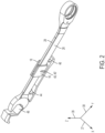
Figure 2 is a perspective view of a cutaway portion of a wrench support rack showing a wrench positioned therein; -
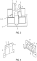
Figure 3 is perspective view of a clamp assembly; -
Figure 4 is an exploded view of a clamp assembly; -
Figure 5 is cutaway view showing a stem of a wrench positioned in a clamp assembly; -
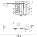
Figure 6 is a plan view of a wrench disposed in a wrench rack support and a cutaway view of the same; and -
Figure 7 is an alternate embodiment of the wrench support rack according to the invention. -
Figure 1 discloses an embodiment of thewrench rack support 10. The wrench support rack includes abase 12. Aclamp assembly 14 is attached to thebase 12. Theclamp assembly 14 comprises avertical stop 16 spaced apart from apush member 18. The space in between thevertical stop 16 and thepush member 18 forms agroove 20 configured to receive astem 26 of awrench 28. (For ease of discussion about the position in which theclamp assembly 14 holds thewrench 28, the axis' of thewrench 28 are also shown inFigure 2 . When held in position in theclamp assembly 14, the z-axis 39 will be vertical.) - As shown in
Figure 2 , theclamp assembly 14 is configured to rigidly hold thestem 26 of awrench 28 in place thereby preventing unwanted removal. Thevertical stop 16 includes at least oneupper ridge portion 22 that is configured to engage thestem 26 of awrench 28. Thevertical stop 16 may also include twoupper ridge portions 22, both of which will engage thestem 26 of awrench 28 and prevent vertical movement of thewrench 28. - Opposite the
vertical stop 16 is apush member 18. Thepush member 18 includes at least oneinward protrusion 24. Thepush member 18 and theinward protrusion 24 are configured to engage thestem 26 of awrench 28 and push/hold it into engagement with thevertical stop 16. - Turning now to
Figure 5 , which is a cutaway of anexemplary clamp assembly 14 holding awrench 28 in place. As previously mentioned, thevertical stop 16 includes at least oneupper ridge portion 22. Generally speaking, theupper ridge portion 22 is substantially pennant or triangular shaped. This general pennant or triangular shape is formed from anupper surface 30 that is positioned at a downward angle (Θ) when measured from its normal 32, and a lower surface 34 that is positioned at an upward angle (β) when measured from its normal 36. Preferably, it should be easier to insert awrench 28 into theclamp assembly 14 than it is to remove it. In order to achieve this preference, the angle (Θ) of theupper surface 30 should always be greater than the angle (β) of the lower surface 34. -
Figure 5 also shows the position of theinward protrusion 24 and how it assists in holding a wrench in place. Specifically, theinward protrusion 24 is configured to engage thestem 26 of awrench 28 substantially at or above the y-axis 38 of the wrench. In so doing, the inward protrusion applies a force (represented by arrow 41) at a downward angle. This force holds the wrench in place against both thebase 12 and thevertical stop 16. - Over the life of the product, the insertion and removal of wrenches from the
clamp assembly 14 may lead to a bending / bowing of the material used to craft thevertical stop 16 and pushmember 18.Figure 4 shows the manner in which thevertical stop 16 and thepush member 18 may bend / bow. The thickbroken lines vertical stop 16 and pushmember 18 when there is not a wrench positioned there between. When a wrench is positioned in between thevertical stop 16 and thepush member 18, forces represented byarrows forces vertical stop 16 and pushmember 16 to respectively bend and bow as represented by the thinbroken lines vertical stop 16 and pushmember 18 to permanently stay in these respective bent / bowed positions. In order to prevent this from happening,support ribs 40, 42 may optionally be attached to thevertical stop 16 and/or thepush member 18. (SeeFigure 5 ). If used,support ribs 40, 42 would be attached to thebase 12 and the respective sides of thevertical stop 16 and pushmember 18 that are opposite thegroove 20. - In addition to the
clamp assembly 14, thebase 12 of thewrench support rack 10 may also include one or more ribs that are designed to support a wrench disposed ingroove 20. For example,neck support rib 44 may include arecess 45 that is configured to receive aneck 29 of awrench 28. When aneck 29 of awrench 28 is positioned inrecess 45, the downward motion of thewrench 28 is limited. Arear support rib 46 may also be attached to thebase 12. Similar to theneck support rib 44, therear support rib 46 may also include arecess 47 that is configured to support astem 26 of awrench 28. When astem 26 of awrench 28 is positioned inrecess 47, the downward movement ofwrench 28 is limited. In a preferred embodiment, theneck support rib 44 and therear support rib 46 are spaced apart and theclamp assembly 14 is disposed there between. - The base 12 may also include an
open head support 48. More specifically, the open head support may be integral to thebase 12. Theopen head support 48 is configured to engage asingle tine 50 of awrench 28. When atine 50 of awrench 28 is engaged to theopen head support 48, the upward movement of thewrench 28 is limited by theopen head support 48. - For added security, the
wrench support rack 10 may also include aretention door 54. Theretention door 54 may be pivotally attached to a side 55 of thebase 12 and is configured to move between an open position and a closed position wherein theretention door 54 pivots over the top of theclamp assembly 14. When in a closed position, theretention door 54 may be secured to anotherside 57 of thebase 12. Those skilled in the art will recognize that thepivot 59 of theretention door 54 may be achieved in a variety of known methods. - As shown in
Figure 1 , theretention door 54 may also include ahorizontal rib 56. Thehorizontal rib 56 may be attached to aninterior side 61 of theretention door 54. Thehorizontal rib 56 may be configured to engage astem 26 of awrench 28 when theretention door 54 is in a closed position. This engagement provides an additional measure of security thereby further preventing unwanted movement of wrenches disposed in thewrench rack support 10. Thehorizontal rib 56 may be tapered such that when theretention door 54 is closed, thehorizontal rib 56 may engage multiple wrenches of varying sizes. - In an alternate embodiment, as shown in
Figure 7 , theretention door 54 does not include ahorizontal rib 56. Instead, theinterior side 61 of theretention door 54 includes at least one door clamp assembly 14'. The door clamp assembly 14' functions identically to that of theclamp assembly 14 discussed above. For ease of explanation, similar elements will be given the same reference numeral. However, door related items will be labelled with a prime. The door clamp assembly 14' comprises a door vertical stop 16' spaced apart from a door push member 18'. The space between the door vertical stop 16' and the door push member 18' forms a door groove 20' configured to receive a stem of a wrench. The door vertical stop 16' includes an upper ridge portion 22' configured to engage a stem of a wrench and limit vertical movement of a wrench disposed in the door groove 20'. The door push member 18' includes an inward protrusion 24' configured to press a stem of a wrench in to the door vertical stop 16' and limit horizontal movement of a wrench disposed in the door groove 20'. - As shown in
Figure 5 , the upper ridge portion 22' of the door vertical stop 16' is substantially pennant or triangular shaped. This general pennant or triangular shape is formed from an upper surface 30' that is positioned at a downward angle (Θ) when measured from its normal 32', and a lower surface 34' that is positioned at an upward angle (β) when measured from its normal 36'. Preferably, it should be easier to insert awrench 28 into the door clamp assembly 14' than it is to remove it. In order to achieve this preference, the angle (Θ) of the upper surface 30' should always be greater than the angle (β) of the lower surface 34'. -
Figure 5 also shows the position of the inward protrusion 24' and how it assists in holding a wrench in place. Specifically, the inward protrusion 24' is configured to engage thestem 26 of a 28 wrench substantially at or above the y-axis 38 of the wrench. In so doing, the inward protrusion 24' applies a force (represented by arrow 41) at a downward angle. This force holds the wrench in place against both theretention door 54 and the door vertical stop 16'. Over the life of the product, the insertion and removal of wrenches from the door clamp assembly 14' may lead to a bending or bowing of the material used to craft the door vertical stop 16' and door push member 18'. Therefore, support ribs 40', 42' may optionally be attached to the door vertical stop 16' and/or the door push member 18'. If used, support ribs 40', 42' would be attached to theretention door 54 and the respective sides of the door vertical stop 16' and door push member 18' that are opposite the door groove 20'. - In addition to the door clamp assembly 14', the
retention door 54 of the wrench support rack may also include one or more support ribs that are designed to support a wrench disposed in door groove 20'. For example, door neck support rib 44' may include a recess 45' that is configured to receive aneck 29 of awrench 28. When aneck 29 of awrench 28 is positioned in recess 45', the downward motion of thewrench 28 is limited. A door rear support rib 46' may also be attached to theretention door 54. Similar to the door neck support rib 44', the door rear support rib 46' may also include a recess 47' that is configured to support astem 26 of awrench 28. When astem 26 of awrench 28 is positioned in recess 47', the downward movement ofwrench 28 is limited. In a preferred embodiment, the door neck support rib 44' and the door rear support rib 46' are spaced apart and the door clamp assembly 14' is disposed there between. - The
retention door 54 may also include an door open head support 48'. The door open head support 48' may be integral to theretention door 54. The door open head support 48' is configured to engage asingle tine 50 of awrench 28. When atine 50 of awrench 28 is engaged to the open head support 48', the upward movement of thewrench 28 is limited by the door open head support 48'. - Persons with ordinary skill in the art will recognize that the
wrench rack support 10 disclosed herein may havemultiple clamp assemblies 14, 14' to accommodate multiple wrenches of varying sizes. In order to achieve this, theclamp assemblies 14, 14' will also vary in size according to the sizes of the wrenches to be accommodated. Similarly, therecess 45,45' ofneck support rib 44/door neck support rib 44' and therecess 47, 47' ofrear support rib 46/door rear support rib 46' may also vary in size to accommodate multiple wrenches of varying size. Theopen head support 48/door open head support 48', however, will not vary in size to accommodate wrenches of varying size. Instead, the varying sizes ofrecesses open head support 48/door open head support 48'. - The
wrench support rack 10 disclosed herein is designed to hold one or more wrenches rigidly in place and prevent unwanted movement of the same. In order to achieve this, a user will position a wrench in her hand such that the z-axis 39 is substantially vertical. The user will then insert the head 49 of thewrench 28 into thewrench support rack 10 such that atine 50 is beneath theopen head support 48.Wrench 28 may then be rotated such thattine 50 is moved upward so that it is engaged with theopen head support 48. At this point, thestem 26 of thewrench 28 is pushed downward until it comes into contact with theclamp assembly 14. Specifically, thestem 26 will be in contact with both theupper surface 30 of thevertical stop 16 and theinward protrusion 24 of thepush member 18. As the user applies downward pressure to thestem 26, it will slide down theupper surface 30 and theinward protrusion 24 intogroove 20. Once thestem 26 clears theupper surface 30 and is moved down intogroove 20, theinward protrusion 24 will press the stem underneath theupper ridge portion 22. Preferably, theclamp assembly 14 is sized appropriately such when thestem 26 of the wrench is pressed fully into thegroove 20,tine 50 will be engaged to theopen head support 48; theneck 29 will be engaged to recess 45 of theneck support rib 44; and the stem will be in simultaneous contact with the lower surface 34 of theupper ridge portion 22, theinward protrusion 24, thebase 12, and therecess 47 of therear support rib 46. Obviously, removal of awrench 28 from thewrench rack support 10 is achieved by reversing the aforementioned steps. - Those skilled in the art will recognize that the foregoing discussion of relating to the insertion and removal of a wrench into a clamp assembly on the base, is equally applicable to the insertion and removal of a wrench into a door clamp assembly described above and shown in
Figure 7 .
Claims (13)
- A wrench support rack (10) comprising:a base (12); andat least one clamp assembly (14) attached to the base (12) and comprising a vertical stop (16) spaced apart from a push member (18), and wherein the space in between the vertical stop (16) and the push member (18) forms a groove (20) configured to receive a stem (26) of a wrench (28), and wherein the vertical stop (16) includes an upper ridge portion (22) configured to engage a stem (26) of a wrench (28) and limit vertical movement of a wrench (28) disposed in the groove (20), and wherein the push member (18) includes an inward protrusion (24) configured to press a stem (26) of a wrench (28) in to the vertical stop (16) and limit horizontal movement of a wrench (28) disposed in the groove (20), andcharacterized in that the base (12 further includes an open head support (48) configured to engage at least one tine (50) of a wrench (28) and limit upward movement of the wrench (28), and wherein the upper ridge (22) portion of the vertical stop (16) is substantially pennant shaped and includes an upper surface (30) that is positioned at a downward angle (θ) from a normal (32), and a lower surface (34) that is positioned at an upward angle (β) from a normal, and wherein the angle (θ) is greater than the angle (β).
- The wrench support rack (10) according to claim 1, wherein the inward protrusion (24) of the push member (18) is configured to primarily engage a stem (26) of a wrench (28) at or above its y-axis such that the wrench is pressed downward into the push member and the base (12).
- The wrench support rack (10) according to any of the preceding claims, wherein the vertical stop (16) includes a support rib (40) attached to the base and the side of the vertical stop that is away from the groove (20).
- The wrench support rack (10) according to any of the preceding claims, wherein the push member (18) includes a support rib (42) attached to the base and the side of the push member that is away from the groove (20).
- The wrench support rack (10) according to any of the preceding claims, wherein the base (12) further includes a neck support rib (44) configured to support a neck (29) of a wrench (28) disposed in the groove (20) and limit downward movement of the wrench.
- The wrench support rack (10) according to any of the preceding claims, wherein the base (12) further includes a rear support rib (46) configured to support a stem (26) of a wrench (28) disposed in the groove (20) and limit downward movement of the wrench.
- The wrench support rack (10) according to any of the preceding claims, wherein the base (12) further defines an aperture (52) configured to receive one or more rails from a hanging sales display rack.
- The wrench support rack (10) according to any of the preceding claims, further comprising a retention door (54) pivotally attached to a side (55) of the base (12) and configured to move between an open position and a closed position wherein the retention door pivots over the top of the at least one clamp assembly (14) and is secured to the opposite side of the base.
- The wrench support rack (10) according to any preceding claim, wherein the retention door (54) further includes horizontal rib (56) attached to an interior side (61) of the retention door (54) and configured to engage at least one stem (26) of a wrench (28) when the retention door (54) is in a closed position.
- The wrench support rack (10) according to claim 5, wherein the retention door (54) further includes at least one door clamp assembly (14') attached to an interior side (61) of the retention door and comprising a door vertical stop (16') spaced apart from a door push member (18'), and wherein the space in between the door vertical stop (16') and the door push member (18') forms a door groove (20') configured to receive a stem (26) of a wrench (28), and wherein the door vertical stop (16') includes an upper ridge portion (22') configured to engage a stem (26) of a wrench (28) and limit vertical movement of a wrench (28) disposed in the door groove (20'), and wherein the door push member (18') includes an inward protrusion (24') configured to press a stem (26) of a wrench (28) in to the door vertical stop (16') and limit horizontal movement of a wrench (28) disposed in the door groove (20').
- The wrench support rack (10) according to claim 6, wherein the upper ridge portion (22') of the door vertical stop (16') is substantially pennant shaped and includes an upper surface (30') that is positioned at a downward angle (θ) from a normal (32'), and a lower surface (34') that is positioned at an upward angle (β) from a normal (36'), and wherein the angle (θ) is greater than the angle (β).
- The wrench support rack (10) according to claim 6 or claim 7, wherein the inward protrusion (24') of the door push member (18') is configured to primarily engage a stem (26) of a wrench (28) at or above its y-axis such that the wrench is pressed downward into the door push member (and the door (54).
- The wrench support rack (10) according to any of claims 5 to 8, wherein the retention door (54) further includes a door open head support (48') configured engage a tine (50) of a wrench (28) and limit upward movement of the wrench.
Applications Claiming Priority (2)
| Application Number | Priority Date | Filing Date | Title |
|---|---|---|---|
| US15/690,455 US10524590B2 (en) | 2017-08-30 | 2017-08-30 | Wrench support rack assembly |
| PCT/CN2018/103257 WO2019042358A1 (en) | 2017-08-30 | 2018-08-30 | Wrench support rack assembly |
Publications (3)
| Publication Number | Publication Date |
|---|---|
| EP3676056A1 EP3676056A1 (en) | 2020-07-08 |
| EP3676056A4 EP3676056A4 (en) | 2020-12-30 |
| EP3676056B1 true EP3676056B1 (en) | 2023-03-29 |
Family
ID=65436587
Family Applications (1)
| Application Number | Title | Priority Date | Filing Date |
|---|---|---|---|
| EP18851185.1A Active EP3676056B1 (en) | 2017-08-30 | 2018-08-30 | Wrench support rack assembly |
Country Status (4)
| Country | Link |
|---|---|
| US (1) | US10524590B2 (en) |
| EP (1) | EP3676056B1 (en) |
| CN (1) | CN111263684B (en) |
| WO (1) | WO2019042358A1 (en) |
Families Citing this family (11)
| Publication number | Priority date | Publication date | Assignee | Title |
|---|---|---|---|---|
| USD891940S1 (en) * | 2019-06-29 | 2020-08-04 | Church & Dwight Co., Inc. | Blade dispenser |
| USD907512S1 (en) | 2019-06-29 | 2021-01-12 | Church & Dwight Co., Inc. | Blade dispenser |
| USD1084810S1 (en) * | 2021-01-14 | 2025-07-22 | Stanley Chiro International Ltd. | Wrench rack |
| WO2023097184A1 (en) * | 2021-11-24 | 2023-06-01 | Milwaukee Electric Tool Corporation | Pliers storage rack |
| DE112022004111T5 (en) | 2021-11-24 | 2024-08-08 | Milwaukee Electric Tool Corporation | PLIERS STORAGE RACK |
| USD1024557S1 (en) | 2022-06-08 | 2024-04-30 | Yeti Coolers, Llc | Container |
| USD1063376S1 (en) | 2022-06-08 | 2025-02-25 | Yeti Coolers, Llc | Container |
| US11912477B2 (en) | 2022-06-08 | 2024-02-27 | Yeti Coolers, Llc | Container with handle and latching system |
| USD1036116S1 (en) | 2022-06-08 | 2024-07-23 | Yeti Coolers, Llc | Container |
| USD1036119S1 (en) | 2022-11-30 | 2024-07-23 | Yeti Coolers, Llc | Container |
| USD1108237S1 (en) * | 2024-03-29 | 2026-01-06 | Yantai Greenery Tools Co., Ltd. | Wrench storage rack |
Family Cites Families (21)
| Publication number | Priority date | Publication date | Assignee | Title |
|---|---|---|---|---|
| US5346063A (en) * | 1993-04-27 | 1994-09-13 | Jessie Chow | Tool holder |
| US5598924A (en) * | 1995-10-06 | 1997-02-04 | Chiro Tool Mfg Corp. | Spanner holder |
| US5967340A (en) * | 1998-08-11 | 1999-10-19 | Kao; Jui-Chien | Tool rack having slidable connectors |
| US6202864B1 (en) * | 1999-03-08 | 2001-03-20 | Gregory R. Ernst | Lock securing elongate articles to a holder |
| US6315121B1 (en) * | 2000-10-05 | 2001-11-13 | Donald Hansen | Wrench rack |
| US6536611B2 (en) * | 2000-10-06 | 2003-03-25 | Ander Chen | Wrench suspension rack assembly |
| US6712224B2 (en) * | 2001-07-16 | 2004-03-30 | Hand Tool Design Corporation | Tool rack assembly |
| US20030016993A1 (en) * | 2001-07-17 | 2003-01-23 | Ching Chen | Tool kit with replaceable tool anchor device |
| US6401923B1 (en) * | 2001-11-13 | 2002-06-11 | Stanley Chiro International Ltd. | Tool packaging and displaying device |
| TW507657U (en) * | 2002-01-25 | 2002-10-21 | Shiou-Jen Lin | Clip-buckle type wrench rack |
| US20030183591A1 (en) * | 2002-04-02 | 2003-10-02 | David Ling | Tool display board |
| TW573597U (en) * | 2002-07-01 | 2004-01-21 | Stanley Chiro Int Ltd | Wrench rack with two-stage burglarproof locking and buckling apparatus |
| US6679391B1 (en) * | 2002-08-29 | 2004-01-20 | Stanley Chiro International Ltd. | Wrench support rack assembly |
| US7055689B2 (en) * | 2002-11-18 | 2006-06-06 | Terence Chen | Hanger for wrenches |
| GB2406611B (en) * | 2003-10-03 | 2006-07-19 | Jui-Chien Kao | Tool suspension plate |
| US7717278B2 (en) * | 2008-07-07 | 2010-05-18 | Jui-Chien Kao | Tool suspension device |
| US8047386B2 (en) * | 2009-04-08 | 2011-11-01 | Infar Industrial Co., Ltd. | Tool rack with multi-function |
| US7938261B1 (en) * | 2009-12-10 | 2011-05-10 | Kung-Cheng Chen | Hand tool display box |
| US8261911B2 (en) * | 2010-12-06 | 2012-09-11 | Hong-Jen Lee | Portable wrench holder |
| US9962827B2 (en) * | 2016-03-24 | 2018-05-08 | Jui-Chien Kao | Hand tool frame |
| US9656385B1 (en) * | 2016-03-29 | 2017-05-23 | Jui-Chien Kao | Hand tool frame |
-
2017
- 2017-08-30 US US15/690,455 patent/US10524590B2/en active Active
-
2018
- 2018-08-30 WO PCT/CN2018/103257 patent/WO2019042358A1/en not_active Ceased
- 2018-08-30 CN CN201880056803.5A patent/CN111263684B/en active Active
- 2018-08-30 EP EP18851185.1A patent/EP3676056B1/en active Active
Also Published As
| Publication number | Publication date |
|---|---|
| CN111263684B (en) | 2023-07-18 |
| US20190059614A1 (en) | 2019-02-28 |
| CN111263684A (en) | 2020-06-09 |
| EP3676056A1 (en) | 2020-07-08 |
| EP3676056A4 (en) | 2020-12-30 |
| WO2019042358A1 (en) | 2019-03-07 |
| US10524590B2 (en) | 2020-01-07 |
Similar Documents
| Publication | Publication Date | Title |
|---|---|---|
| US10524590B2 (en) | Wrench support rack assembly | |
| US6536611B2 (en) | Wrench suspension rack assembly | |
| US9656385B1 (en) | Hand tool frame | |
| US5598924A (en) | Spanner holder | |
| US9962827B2 (en) | Hand tool frame | |
| US9694491B1 (en) | Hand tool frame | |
| US4681233A (en) | Pegboard mounted tool holder | |
| US10022857B2 (en) | Hand tool frame | |
| US7523832B2 (en) | Suspension display rack | |
| EP3149255B1 (en) | Torsion spring metal ceiling system and hardware | |
| US6966165B2 (en) | Apparatus for displaying tools and merchandising method | |
| US20180290292A1 (en) | Adjustable Tool Holder | |
| JP2003220582A (en) | Grasping type spanner rack | |
| US20090266952A1 (en) | Magnetic Organizer | |
| US4558856A (en) | Holder for vise parallels | |
| US20040016667A1 (en) | Tool box having a ratchet tool test base | |
| US5346167A (en) | Peg board hanger | |
| TWI619889B (en) | Clips and information display cards mounted on the clips | |
| US20060260963A1 (en) | Toolbox for displaying tools | |
| CN119059076A (en) | Multipurpose Pallet | |
| GB2444876A (en) | Anti-theft tool suspension display rack | |
| KR200476965Y1 (en) | Monitor mounting device and pos apparatus having the same | |
| JP7584789B2 (en) | Display equipment | |
| US5983547A (en) | Toggle actuated artwork retainer | |
| US20070138723A1 (en) | Clamping device having replaceable clamping members |
Legal Events
| Date | Code | Title | Description |
|---|---|---|---|
| STAA | Information on the status of an ep patent application or granted ep patent |
Free format text: STATUS: THE INTERNATIONAL PUBLICATION HAS BEEN MADE |
|
| PUAI | Public reference made under article 153(3) epc to a published international application that has entered the european phase |
Free format text: ORIGINAL CODE: 0009012 |
|
| STAA | Information on the status of an ep patent application or granted ep patent |
Free format text: STATUS: REQUEST FOR EXAMINATION WAS MADE |
|
| 17P | Request for examination filed |
Effective date: 20200310 |
|
| AK | Designated contracting states |
Kind code of ref document: A1 Designated state(s): AL AT BE BG CH CY CZ DE DK EE ES FI FR GB GR HR HU IE IS IT LI LT LU LV MC MK MT NL NO PL PT RO RS SE SI SK SM TR |
|
| AX | Request for extension of the european patent |
Extension state: BA ME |
|
| DAV | Request for validation of the european patent (deleted) | ||
| DAX | Request for extension of the european patent (deleted) | ||
| A4 | Supplementary search report drawn up and despatched |
Effective date: 20201202 |
|
| RIC1 | Information provided on ipc code assigned before grant |
Ipc: B25H 3/00 20060101AFI20201126BHEP Ipc: B25B 13/56 20060101ALI20201126BHEP Ipc: B25H 3/04 20060101ALI20201126BHEP |
|
| REG | Reference to a national code |
Ref country code: DE Ref legal event code: R079 Ref document number: 602018047873 Country of ref document: DE Free format text: PREVIOUS MAIN CLASS: B25H0003020000 Ipc: B25H0003000000 |
|
| GRAP | Despatch of communication of intention to grant a patent |
Free format text: ORIGINAL CODE: EPIDOSNIGR1 |
|
| STAA | Information on the status of an ep patent application or granted ep patent |
Free format text: STATUS: GRANT OF PATENT IS INTENDED |
|
| RIC1 | Information provided on ipc code assigned before grant |
Ipc: B25H 3/04 20060101ALI20221201BHEP Ipc: B25B 13/56 20060101ALI20221201BHEP Ipc: B25H 3/00 20060101AFI20221201BHEP |
|
| INTG | Intention to grant announced |
Effective date: 20230104 |
|
| GRAS | Grant fee paid |
Free format text: ORIGINAL CODE: EPIDOSNIGR3 |
|
| GRAA | (expected) grant |
Free format text: ORIGINAL CODE: 0009210 |
|
| STAA | Information on the status of an ep patent application or granted ep patent |
Free format text: STATUS: THE PATENT HAS BEEN GRANTED |
|
| AK | Designated contracting states |
Kind code of ref document: B1 Designated state(s): AL AT BE BG CH CY CZ DE DK EE ES FI FR GB GR HR HU IE IS IT LI LT LU LV MC MK MT NL NO PL PT RO RS SE SI SK SM TR |
|
| REG | Reference to a national code |
Ref country code: CH Ref legal event code: EP |
|
| REG | Reference to a national code |
Ref country code: DE Ref legal event code: R096 Ref document number: 602018047873 Country of ref document: DE |
|
| REG | Reference to a national code |
Ref country code: AT Ref legal event code: REF Ref document number: 1556353 Country of ref document: AT Kind code of ref document: T Effective date: 20230415 |
|
| REG | Reference to a national code |
Ref country code: IE Ref legal event code: FG4D |
|
| REG | Reference to a national code |
Ref country code: LT Ref legal event code: MG9D |
|
| PG25 | Lapsed in a contracting state [announced via postgrant information from national office to epo] |
Ref country code: RS Free format text: LAPSE BECAUSE OF FAILURE TO SUBMIT A TRANSLATION OF THE DESCRIPTION OR TO PAY THE FEE WITHIN THE PRESCRIBED TIME-LIMIT Effective date: 20230329 Ref country code: NO Free format text: LAPSE BECAUSE OF FAILURE TO SUBMIT A TRANSLATION OF THE DESCRIPTION OR TO PAY THE FEE WITHIN THE PRESCRIBED TIME-LIMIT Effective date: 20230629 Ref country code: LV Free format text: LAPSE BECAUSE OF FAILURE TO SUBMIT A TRANSLATION OF THE DESCRIPTION OR TO PAY THE FEE WITHIN THE PRESCRIBED TIME-LIMIT Effective date: 20230329 Ref country code: LT Free format text: LAPSE BECAUSE OF FAILURE TO SUBMIT A TRANSLATION OF THE DESCRIPTION OR TO PAY THE FEE WITHIN THE PRESCRIBED TIME-LIMIT Effective date: 20230329 Ref country code: HR Free format text: LAPSE BECAUSE OF FAILURE TO SUBMIT A TRANSLATION OF THE DESCRIPTION OR TO PAY THE FEE WITHIN THE PRESCRIBED TIME-LIMIT Effective date: 20230329 |
|
| REG | Reference to a national code |
Ref country code: NL Ref legal event code: MP Effective date: 20230329 |
|
| REG | Reference to a national code |
Ref country code: AT Ref legal event code: MK05 Ref document number: 1556353 Country of ref document: AT Kind code of ref document: T Effective date: 20230329 |
|
| PG25 | Lapsed in a contracting state [announced via postgrant information from national office to epo] |
Ref country code: SE Free format text: LAPSE BECAUSE OF FAILURE TO SUBMIT A TRANSLATION OF THE DESCRIPTION OR TO PAY THE FEE WITHIN THE PRESCRIBED TIME-LIMIT Effective date: 20230329 Ref country code: NL Free format text: LAPSE BECAUSE OF FAILURE TO SUBMIT A TRANSLATION OF THE DESCRIPTION OR TO PAY THE FEE WITHIN THE PRESCRIBED TIME-LIMIT Effective date: 20230329 Ref country code: GR Free format text: LAPSE BECAUSE OF FAILURE TO SUBMIT A TRANSLATION OF THE DESCRIPTION OR TO PAY THE FEE WITHIN THE PRESCRIBED TIME-LIMIT Effective date: 20230630 Ref country code: FI Free format text: LAPSE BECAUSE OF FAILURE TO SUBMIT A TRANSLATION OF THE DESCRIPTION OR TO PAY THE FEE WITHIN THE PRESCRIBED TIME-LIMIT Effective date: 20230329 |
|
| P01 | Opt-out of the competence of the unified patent court (upc) registered |
Effective date: 20230912 |
|
| PG25 | Lapsed in a contracting state [announced via postgrant information from national office to epo] |
Ref country code: SM Free format text: LAPSE BECAUSE OF FAILURE TO SUBMIT A TRANSLATION OF THE DESCRIPTION OR TO PAY THE FEE WITHIN THE PRESCRIBED TIME-LIMIT Effective date: 20230329 Ref country code: RO Free format text: LAPSE BECAUSE OF FAILURE TO SUBMIT A TRANSLATION OF THE DESCRIPTION OR TO PAY THE FEE WITHIN THE PRESCRIBED TIME-LIMIT Effective date: 20230329 Ref country code: PT Free format text: LAPSE BECAUSE OF FAILURE TO SUBMIT A TRANSLATION OF THE DESCRIPTION OR TO PAY THE FEE WITHIN THE PRESCRIBED TIME-LIMIT Effective date: 20230731 Ref country code: ES Free format text: LAPSE BECAUSE OF FAILURE TO SUBMIT A TRANSLATION OF THE DESCRIPTION OR TO PAY THE FEE WITHIN THE PRESCRIBED TIME-LIMIT Effective date: 20230329 Ref country code: EE Free format text: LAPSE BECAUSE OF FAILURE TO SUBMIT A TRANSLATION OF THE DESCRIPTION OR TO PAY THE FEE WITHIN THE PRESCRIBED TIME-LIMIT Effective date: 20230329 Ref country code: AT Free format text: LAPSE BECAUSE OF FAILURE TO SUBMIT A TRANSLATION OF THE DESCRIPTION OR TO PAY THE FEE WITHIN THE PRESCRIBED TIME-LIMIT Effective date: 20230329 |
|
| PG25 | Lapsed in a contracting state [announced via postgrant information from national office to epo] |
Ref country code: SK Free format text: LAPSE BECAUSE OF FAILURE TO SUBMIT A TRANSLATION OF THE DESCRIPTION OR TO PAY THE FEE WITHIN THE PRESCRIBED TIME-LIMIT Effective date: 20230329 Ref country code: PL Free format text: LAPSE BECAUSE OF FAILURE TO SUBMIT A TRANSLATION OF THE DESCRIPTION OR TO PAY THE FEE WITHIN THE PRESCRIBED TIME-LIMIT Effective date: 20230329 Ref country code: IS Free format text: LAPSE BECAUSE OF FAILURE TO SUBMIT A TRANSLATION OF THE DESCRIPTION OR TO PAY THE FEE WITHIN THE PRESCRIBED TIME-LIMIT Effective date: 20230729 |
|
| REG | Reference to a national code |
Ref country code: DE Ref legal event code: R097 Ref document number: 602018047873 Country of ref document: DE |
|
| PG25 | Lapsed in a contracting state [announced via postgrant information from national office to epo] |
Ref country code: DK Free format text: LAPSE BECAUSE OF FAILURE TO SUBMIT A TRANSLATION OF THE DESCRIPTION OR TO PAY THE FEE WITHIN THE PRESCRIBED TIME-LIMIT Effective date: 20230329 Ref country code: CZ Free format text: LAPSE BECAUSE OF FAILURE TO SUBMIT A TRANSLATION OF THE DESCRIPTION OR TO PAY THE FEE WITHIN THE PRESCRIBED TIME-LIMIT Effective date: 20230329 |
|
| PLBE | No opposition filed within time limit |
Free format text: ORIGINAL CODE: 0009261 |
|
| STAA | Information on the status of an ep patent application or granted ep patent |
Free format text: STATUS: NO OPPOSITION FILED WITHIN TIME LIMIT |
|
| 26N | No opposition filed |
Effective date: 20240103 |
|
| PG25 | Lapsed in a contracting state [announced via postgrant information from national office to epo] |
Ref country code: MC Free format text: LAPSE BECAUSE OF FAILURE TO SUBMIT A TRANSLATION OF THE DESCRIPTION OR TO PAY THE FEE WITHIN THE PRESCRIBED TIME-LIMIT Effective date: 20230329 |
|
| REG | Reference to a national code |
Ref country code: CH Ref legal event code: PL |
|
| PG25 | Lapsed in a contracting state [announced via postgrant information from national office to epo] |
Ref country code: MC Free format text: LAPSE BECAUSE OF FAILURE TO SUBMIT A TRANSLATION OF THE DESCRIPTION OR TO PAY THE FEE WITHIN THE PRESCRIBED TIME-LIMIT Effective date: 20230329 |
|
| PG25 | Lapsed in a contracting state [announced via postgrant information from national office to epo] |
Ref country code: LU Free format text: LAPSE BECAUSE OF NON-PAYMENT OF DUE FEES Effective date: 20230830 |
|
| PG25 | Lapsed in a contracting state [announced via postgrant information from national office to epo] |
Ref country code: LU Free format text: LAPSE BECAUSE OF NON-PAYMENT OF DUE FEES Effective date: 20230830 Ref country code: CH Free format text: LAPSE BECAUSE OF NON-PAYMENT OF DUE FEES Effective date: 20230831 |
|
| PG25 | Lapsed in a contracting state [announced via postgrant information from national office to epo] |
Ref country code: SI Free format text: LAPSE BECAUSE OF FAILURE TO SUBMIT A TRANSLATION OF THE DESCRIPTION OR TO PAY THE FEE WITHIN THE PRESCRIBED TIME-LIMIT Effective date: 20230329 |
|
| REG | Reference to a national code |
Ref country code: BE Ref legal event code: MM Effective date: 20230831 |
|
| REG | Reference to a national code |
Ref country code: IE Ref legal event code: MM4A |
|
| PG25 | Lapsed in a contracting state [announced via postgrant information from national office to epo] |
Ref country code: SI Free format text: LAPSE BECAUSE OF FAILURE TO SUBMIT A TRANSLATION OF THE DESCRIPTION OR TO PAY THE FEE WITHIN THE PRESCRIBED TIME-LIMIT Effective date: 20230329 Ref country code: IT Free format text: LAPSE BECAUSE OF FAILURE TO SUBMIT A TRANSLATION OF THE DESCRIPTION OR TO PAY THE FEE WITHIN THE PRESCRIBED TIME-LIMIT Effective date: 20230329 |
|
| PG25 | Lapsed in a contracting state [announced via postgrant information from national office to epo] |
Ref country code: IE Free format text: LAPSE BECAUSE OF NON-PAYMENT OF DUE FEES Effective date: 20230830 |
|
| PG25 | Lapsed in a contracting state [announced via postgrant information from national office to epo] |
Ref country code: IE Free format text: LAPSE BECAUSE OF NON-PAYMENT OF DUE FEES Effective date: 20230830 Ref country code: FR Free format text: LAPSE BECAUSE OF NON-PAYMENT OF DUE FEES Effective date: 20230831 |
|
| PG25 | Lapsed in a contracting state [announced via postgrant information from national office to epo] |
Ref country code: BE Free format text: LAPSE BECAUSE OF NON-PAYMENT OF DUE FEES Effective date: 20230831 |
|
| PG25 | Lapsed in a contracting state [announced via postgrant information from national office to epo] |
Ref country code: BG Free format text: LAPSE BECAUSE OF FAILURE TO SUBMIT A TRANSLATION OF THE DESCRIPTION OR TO PAY THE FEE WITHIN THE PRESCRIBED TIME-LIMIT Effective date: 20230329 |
|
| PG25 | Lapsed in a contracting state [announced via postgrant information from national office to epo] |
Ref country code: BG Free format text: LAPSE BECAUSE OF FAILURE TO SUBMIT A TRANSLATION OF THE DESCRIPTION OR TO PAY THE FEE WITHIN THE PRESCRIBED TIME-LIMIT Effective date: 20230329 |
|
| PG25 | Lapsed in a contracting state [announced via postgrant information from national office to epo] |
Ref country code: CY Free format text: LAPSE BECAUSE OF FAILURE TO SUBMIT A TRANSLATION OF THE DESCRIPTION OR TO PAY THE FEE WITHIN THE PRESCRIBED TIME-LIMIT; INVALID AB INITIO Effective date: 20180830 |
|
| PG25 | Lapsed in a contracting state [announced via postgrant information from national office to epo] |
Ref country code: HU Free format text: LAPSE BECAUSE OF FAILURE TO SUBMIT A TRANSLATION OF THE DESCRIPTION OR TO PAY THE FEE WITHIN THE PRESCRIBED TIME-LIMIT; INVALID AB INITIO Effective date: 20180830 |
|
| PGFP | Annual fee paid to national office [announced via postgrant information from national office to epo] |
Ref country code: DE Payment date: 20250819 Year of fee payment: 8 |
|
| PGFP | Annual fee paid to national office [announced via postgrant information from national office to epo] |
Ref country code: GB Payment date: 20250822 Year of fee payment: 8 |
|
| PG25 | Lapsed in a contracting state [announced via postgrant information from national office to epo] |
Ref country code: TR Free format text: LAPSE BECAUSE OF FAILURE TO SUBMIT A TRANSLATION OF THE DESCRIPTION OR TO PAY THE FEE WITHIN THE PRESCRIBED TIME-LIMIT Effective date: 20230329 |