EP3675617A1 - Vehicle lower portion structure - Google Patents
Vehicle lower portion structure Download PDFInfo
- Publication number
- EP3675617A1 EP3675617A1 EP19219454.6A EP19219454A EP3675617A1 EP 3675617 A1 EP3675617 A1 EP 3675617A1 EP 19219454 A EP19219454 A EP 19219454A EP 3675617 A1 EP3675617 A1 EP 3675617A1
- Authority
- EP
- European Patent Office
- Prior art keywords
- vehicle
- backing layer
- lower portion
- dispersed
- electromagnetic wave
- Prior art date
- Legal status (The legal status is an assumption and is not a legal conclusion. Google has not performed a legal analysis and makes no representation as to the accuracy of the status listed.)
- Granted
Links
Images


Classifications
-
- B—PERFORMING OPERATIONS; TRANSPORTING
- B60—VEHICLES IN GENERAL
- B60N—SEATS SPECIALLY ADAPTED FOR VEHICLES; VEHICLE PASSENGER ACCOMMODATION NOT OTHERWISE PROVIDED FOR
- B60N3/00—Arrangements or adaptations of other passenger fittings, not otherwise provided for
- B60N3/04—Arrangements or adaptations of other passenger fittings, not otherwise provided for of floor mats or carpets
- B60N3/048—Arrangements or adaptations of other passenger fittings, not otherwise provided for of floor mats or carpets characterised by their structure
-
- B—PERFORMING OPERATIONS; TRANSPORTING
- B60—VEHICLES IN GENERAL
- B60N—SEATS SPECIALLY ADAPTED FOR VEHICLES; VEHICLE PASSENGER ACCOMMODATION NOT OTHERWISE PROVIDED FOR
- B60N3/00—Arrangements or adaptations of other passenger fittings, not otherwise provided for
- B60N3/04—Arrangements or adaptations of other passenger fittings, not otherwise provided for of floor mats or carpets
- B60N3/046—Arrangements or adaptations of other passenger fittings, not otherwise provided for of floor mats or carpets characterised by the fixing means
-
- B—PERFORMING OPERATIONS; TRANSPORTING
- B62—LAND VEHICLES FOR TRAVELLING OTHERWISE THAN ON RAILS
- B62D—MOTOR VEHICLES; TRAILERS
- B62D25/00—Superstructure or monocoque structure sub-units; Parts or details thereof not otherwise provided for
- B62D25/20—Floors or bottom sub-units
-
- B—PERFORMING OPERATIONS; TRANSPORTING
- B60—VEHICLES IN GENERAL
- B60K—ARRANGEMENT OR MOUNTING OF PROPULSION UNITS OR OF TRANSMISSIONS IN VEHICLES; ARRANGEMENT OR MOUNTING OF PLURAL DIVERSE PRIME-MOVERS IN VEHICLES; AUXILIARY DRIVES FOR VEHICLES; INSTRUMENTATION OR DASHBOARDS FOR VEHICLES; ARRANGEMENTS IN CONNECTION WITH COOLING, AIR INTAKE, GAS EXHAUST OR FUEL SUPPLY OF PROPULSION UNITS IN VEHICLES
- B60K1/00—Arrangement or mounting of electrical propulsion units
-
- B—PERFORMING OPERATIONS; TRANSPORTING
- B60—VEHICLES IN GENERAL
- B60L—PROPULSION OF ELECTRICALLY-PROPELLED VEHICLES; SUPPLYING ELECTRIC POWER FOR AUXILIARY EQUIPMENT OF ELECTRICALLY-PROPELLED VEHICLES; ELECTRODYNAMIC BRAKE SYSTEMS FOR VEHICLES IN GENERAL; MAGNETIC SUSPENSION OR LEVITATION FOR VEHICLES; MONITORING OPERATING VARIABLES OF ELECTRICALLY-PROPELLED VEHICLES; ELECTRIC SAFETY DEVICES FOR ELECTRICALLY-PROPELLED VEHICLES
- B60L50/00—Electric propulsion with power supplied within the vehicle
- B60L50/50—Electric propulsion with power supplied within the vehicle using propulsion power supplied by batteries or fuel cells
- B60L50/60—Electric propulsion with power supplied within the vehicle using propulsion power supplied by batteries or fuel cells using power supplied by batteries
- B60L50/66—Arrangements of batteries
-
- B—PERFORMING OPERATIONS; TRANSPORTING
- B60—VEHICLES IN GENERAL
- B60N—SEATS SPECIALLY ADAPTED FOR VEHICLES; VEHICLE PASSENGER ACCOMMODATION NOT OTHERWISE PROVIDED FOR
- B60N3/00—Arrangements or adaptations of other passenger fittings, not otherwise provided for
- B60N3/04—Arrangements or adaptations of other passenger fittings, not otherwise provided for of floor mats or carpets
- B60N3/042—Arrangements or adaptations of other passenger fittings, not otherwise provided for of floor mats or carpets of carpets
-
- B—PERFORMING OPERATIONS; TRANSPORTING
- B60—VEHICLES IN GENERAL
- B60R—VEHICLES, VEHICLE FITTINGS, OR VEHICLE PARTS, NOT OTHERWISE PROVIDED FOR
- B60R16/00—Electric or fluid circuits specially adapted for vehicles and not otherwise provided for; Arrangement of elements of electric or fluid circuits specially adapted for vehicles and not otherwise provided for
- B60R16/02—Electric or fluid circuits specially adapted for vehicles and not otherwise provided for; Arrangement of elements of electric or fluid circuits specially adapted for vehicles and not otherwise provided for electric constitutive elements
- B60R16/0207—Wire harnesses
-
- B—PERFORMING OPERATIONS; TRANSPORTING
- B60—VEHICLES IN GENERAL
- B60R—VEHICLES, VEHICLE FITTINGS, OR VEHICLE PARTS, NOT OTHERWISE PROVIDED FOR
- B60R16/00—Electric or fluid circuits specially adapted for vehicles and not otherwise provided for; Arrangement of elements of electric or fluid circuits specially adapted for vehicles and not otherwise provided for
- B60R16/02—Electric or fluid circuits specially adapted for vehicles and not otherwise provided for; Arrangement of elements of electric or fluid circuits specially adapted for vehicles and not otherwise provided for electric constitutive elements
- B60R16/0207—Wire harnesses
- B60R16/0215—Protecting, fastening and routing means therefor
-
- B—PERFORMING OPERATIONS; TRANSPORTING
- B60—VEHICLES IN GENERAL
- B60R—VEHICLES, VEHICLE FITTINGS, OR VEHICLE PARTS, NOT OTHERWISE PROVIDED FOR
- B60R16/00—Electric or fluid circuits specially adapted for vehicles and not otherwise provided for; Arrangement of elements of electric or fluid circuits specially adapted for vehicles and not otherwise provided for
- B60R16/02—Electric or fluid circuits specially adapted for vehicles and not otherwise provided for; Arrangement of elements of electric or fluid circuits specially adapted for vehicles and not otherwise provided for electric constitutive elements
- B60R16/03—Electric or fluid circuits specially adapted for vehicles and not otherwise provided for; Arrangement of elements of electric or fluid circuits specially adapted for vehicles and not otherwise provided for electric constitutive elements for supply of electrical power to vehicle subsystems or for
-
- H—ELECTRICITY
- H05—ELECTRIC TECHNIQUES NOT OTHERWISE PROVIDED FOR
- H05K—PRINTED CIRCUITS; CASINGS OR CONSTRUCTIONAL DETAILS OF ELECTRIC APPARATUS; MANUFACTURE OF ASSEMBLAGES OF ELECTRICAL COMPONENTS
- H05K9/00—Screening of apparatus or components against electric or magnetic fields
- H05K9/0007—Casings
-
- H—ELECTRICITY
- H05—ELECTRIC TECHNIQUES NOT OTHERWISE PROVIDED FOR
- H05K—PRINTED CIRCUITS; CASINGS OR CONSTRUCTIONAL DETAILS OF ELECTRIC APPARATUS; MANUFACTURE OF ASSEMBLAGES OF ELECTRICAL COMPONENTS
- H05K9/00—Screening of apparatus or components against electric or magnetic fields
- H05K9/0073—Shielding materials
- H05K9/0098—Shielding materials for shielding electrical cables
-
- Y—GENERAL TAGGING OF NEW TECHNOLOGICAL DEVELOPMENTS; GENERAL TAGGING OF CROSS-SECTIONAL TECHNOLOGIES SPANNING OVER SEVERAL SECTIONS OF THE IPC; TECHNICAL SUBJECTS COVERED BY FORMER USPC CROSS-REFERENCE ART COLLECTIONS [XRACs] AND DIGESTS
- Y02—TECHNOLOGIES OR APPLICATIONS FOR MITIGATION OR ADAPTATION AGAINST CLIMATE CHANGE
- Y02T—CLIMATE CHANGE MITIGATION TECHNOLOGIES RELATED TO TRANSPORTATION
- Y02T10/00—Road transport of goods or passengers
- Y02T10/60—Other road transportation technologies with climate change mitigation effect
- Y02T10/70—Energy storage systems for electromobility, e.g. batteries
Definitions
- the present disclosure relates to a vehicle lower portion structure.
- this laminated sheet shields electromagnetic waves using an electrically conductive material, it is only able to shield high frequency electromagnetic waves. In other words, this laminated sheet is not able to shield low frequency electromagnetic waves, whose effects on vehicle occupants (i.e., when a human body is exposed thereto) are a cause of concern. In this way, there is still room for improvement in providing a structure that is able to shield vehicle occupants from low frequency electromagnetic waves.
- an object of the present disclosure to provide a vehicle lower portion structure that is able to shield vehicle occupants from low frequency electromagnetic waves.
- a vehicle lower portion structure is provided with electromagnetic wave emitting components that are disposed at a rear surface side of a floor panel provided in a lower portion of a vehicle, and a carpet component that has a backing layer in which is dispersed a magnetic material, and a carpet pile that is provided on a front surface side of the backing layer, and that is disposed at a front surface side of the floor panel.
- magnetic material is dispersed in a backing layer of a carpet component that is disposed at a front surface side of a floor panel.
- electromagnetic waves are emitted from electromagnetic wave emitting components that are disposed at a rear surface side of the floor panel
- the electromagnetic waves whose effects on vehicle occupants (i.e., when a human body is exposed thereto) is a cause of concern are low frequency electromagnetic waves, and magnetic field components contribute to the generation of these.
- a magnetic material is dispersed in a backing layer, the orientation of the magnetic field components of the electromagnetic waves emitted from the electromagnetic wave emitting components is altered by this magnetic material to a direction away from the vehicle occupants. As a result, the vehicle occupants are shielded from the low frequency electromagnetic waves.
- a vehicle lower portion structure according to a second aspect is the vehicle lower portion structure according to the first aspect in which a density of the magnetic material dispersed in portions of the backing layer that correspond to the electromagnetic wave emitting components is higher than a density of the magnetic material dispersed in other portions of the backing layer.
- a density of the magnetic material dispersed in portions of the backing layer that correspond to the electromagnetic wave emitting component is higher than a density of the magnetic material dispersed in other portions of the backing layer. Accordingly, the orientation of the magnetic field components of the electromagnetic waves emitted from the electromagnetic wage emitting components is efficiently altered by this magnetic material to a direction away from the vehicle occupants. As a result, the vehicle occupants are efficiently shielded from the low frequency electromagnetic waves.
- a vehicle lower portion structure according to a third aspect is the vehicle lower portion structure according to the first aspect in which the magnetic material is only dispersed in portions of the backing layer that correspond to the electromagnetic wave emitting components.
- the magnetic material is only dispersed in portions of the backing layer that correspond to the electromagnetic wave emitting components. Accordingly, the orientation of the magnetic field components of the electromagnetic waves emitted from the electromagnetic wage emitting components is efficiently altered by this magnetic material to a direction away from the vehicle occupants. As a result, the vehicle occupants are efficiently shielded from the low frequency electromagnetic waves.
- a vehicle lower portion structure according to a fourth aspect is the vehicle lower portion structure according to the first aspect in which the backing layer is divided into a first portion that corresponds to positions of the electromagnetic wave emitting components, and a second portion that does not correspond to the positions of the electromagnetic wave emitting components, and the magnetic material is only dispersed in the first portion.
- a vehicle lower portion structure is the vehicle lower portion structure according to the first aspect in which the electromagnetic wave emitting components include at least one of a driving apparatus of a vehicle, a high voltage wiring that is connected to the driving apparatus, and a battery pack.
- an arrow UP, an arrow FR, and an arrow RH that are shown in the appropriate drawings respectively indicate a vehicle upward direction, a vehicle forward direction, and a vehicle right-side direction.
- front-rear, left-right, or up-down directions are used in the following description, then, unless specifically stated otherwise, these refer respectively to the front-rear directions of the vehicle, the left-right directions of the vehicle (i.e., the vehicle width direction), and the up-down directions of the vehicle.
- a floor panel 16 that forms part of a vehicle cabin 14 is provided in a lower portion of a vehicle 12 that is provided with the vehicle lower portion structure 10 'according to the present exemplary embodiment.
- the floor panel 16 is formed substantially in a rectangular shape whose longitudinal direction extends in the vehicle front-rear direction when looked at in plan view (see FIG. 2 ).
- a front end portion 16A of the floor panel 16 extends substantially in a circular arc shape such that, as seen in a side view looking from the vehicle width direction, the vehicle cabin 14 side thereof extends upwards and towards the vehicle front side (so as to follow the contour of the front wheel wheelhouse).
- a driving apparatus 22 that is formed by a power control unit (PCU) and a motor and the like is disposed inside an engine room on a vehicle body front side of the front end portion 16A (i.e., on a rear surface side of the front end portion 16A).
- the vehicle 12 is a hybrid vehicle, a fuel cell vehicle, or an electric vehicle.
- a rear end portion 16B of the floor panel 16 extends substantially in a circular arc shape such that, as seen in a side view looking from the vehicle width direction, the vehicle cabin 14 side thereof extends upwards and towards the vehicle rear side (so as to follow the contour of the rear wheel wheelhouse).
- a driving apparatus 24 that is formed by a power control unit (PCU) and a motor and the like is disposed at a vehicle body rear side of the rear end portion 16B, and on the vehicle body front side of a luggage compartment (i.e., on a rear surface side of the rear end portion 16B).
- PCU power control unit
- high voltage wiring 20 is laid between the driving apparatus 22 and the driving apparatus 24 so as to pass through the vehicle body lower side (i.e., the rear surface side) of the floor panel 16, and in a substantially central portion thereof in the vehicle width direction.
- the high voltage wiring 20 together with the driving apparatuses 22 and 24 form the 'electromagnetic wave emitting components' that emit electromagnetic waves in the present exemplary embodiment.
- a battery pack (not shown in the drawings) is disposed at the vehicle body lower side (i.e., on the rear surface side) of the floor panel 16, and this battery pack is also an electromagnetic wave emitting component.
- the floor carpet 30 has a front end portion 30A whose contour matches the contour of the front end portion 16A of the floor panel 16, a rear end portion 30B whose contour matches the contour of the rear end portion 16B of the floor panel 16, and a flat portion 30C whose contour matches the contour of an intermediate portion 16C located between the front end portion 16A and the rear end portion 16B of the floor panel 16.
- the floor carpet 30 has a carpet pile 32, and a backing layer 34 that is provided on an upper surface (i.e., on the front surface side) of the carpet pile 32.
- the carpet pile 32 is formed from resin fibers such as polyamide (PA) resin, or polyethylene terephthalate (PET) resin or the like.
- the backing layer 34 is formed from a resin material such as polyethylene (PE), or polyethylene terephthalate (PET) or the like, or from a rubber material, and is formed so as to inhibit or prevent the carpet pile 32 that covers the upper surface (i.e., the front surface side) thereof from coming loose. Additionally, magnetic powder Mp, which is serving as a magnetic material, is added to the backing layer 34 and is dispersed therein.
- PE polyethylene
- PET polyethylene terephthalate
- the magnetic powder Mp be added in an amount of 80% or more by weight to the backing layer 34, however, the present disclosure is not limited to this, and it is possible for an amount slightly less than this to be added instead.
- Magnetite fine particles which are inexpensive, serve as an example of the magnetic powder Mp, however, the present disclosure is not particularly limited to this.
- the magnetic powder Mp be dispersed predominantly in portions of the backing layer 34 that correspond to (i.e., are located opposite) the high voltage wiring 20 and the drive apparatuses 22 and 24.
- the density of the magnetic powder Mp that is dispersed in portions of the backing layer 34 that correspond to the high voltage wiring 20 and the drive apparatuses 22 and 24 be greater than the density of the magnetic powder Mp (including cases in which no magnetic powder Mp is added in these portions) that is dispersed in other portions of the backing layer 34.
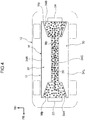
- this type of structure may be achieved by separating the backing layer 34 into plural sections, and adding the magnetic powder Mp separately to each section. More specifically, the backing layer 34 is divided into a front end portion 34A that corresponds to the drive apparatus 22, a rear end portion 34B that corresponds to the drive apparatus 24, an intermediate portion 34C that corresponds to the high voltage wiring 20, and a right side portion 34R and a left side portion 34L that form the remaining portions.
- the magnetic powder Mp is only added to the front end portion 34A, the rear end portion 34B, the intermediate portion 34C, the left side portion 34L and the right side portion 34R.
- the floor carpet 30 is disposed at the upper surface of the floor panel 16.
- the magnetic powder Mp is added to the backing layer 34 of the floor carpet 30 and is dispersed therein.
- electromagnetic waves are emitted from the high voltage wiring 20 and the driving apparatuses 22 and 24, however, the particular electromagnetic waves whose effects on vehicle occupants (i.e., when a human body is exposed thereto) are a cause of concern are low frequency electromagnetic waves, and magnetic field components contribute to the generation of these.
- the magnetic powder Mp is dispersed in the backing layer 34, the orientation of the magnetic field components of the electromagnetic waves emitted from the high voltage wiring 20 and the driving apparatuses 22 and 24 is altered by this magnetic powder Mp to a direction moving away from the vehicle occupants.
- the vehicle occupants can be shielded from the low frequency electromagnetic waves, and any effects on the vehicle occupants caused by these low frequency electromagnetic waves can be inhibited or prevented.
- the density of the magnetic powder Mp that is dispersed in portions of the backing layer 34 that correspond to the high voltage wiring 20 and the drive apparatuses 22 and 24 is greater than the density of the magnetic powder Mp that is dispersed in other portions of the backing layer 34 (i.e., if the magnetic powder Mp is only dispersed in portions of the backing layer 34 that correspond to the high voltage wiring 20 and the drive apparatuses 22 and 24), then the orientation of the magnetic field components of the electromagnetic waves emitted from the high voltage wiring 20 and the driving apparatuses 22 and 24 can be efficiently altered to a direction away from the vehicle occupants. Accordingly, the vehicle occupants can be efficiently shielded from low frequency electromagnetic waves.
- the quantity of magnetic powder that is added to the backing layer 34 can be reduced to the minimum required quantity, and compared with when the magnetic powder Mp is dispersed equally over the entire backing layer 34, not only can any increase in the manufacturing costs of the floor carpet 30 be inhibited, but any increase in the mass (i.e., the weight) of the floor carpet 30 can also be inhibited. Consequently, any deterioration in the fuel consumption of the vehicle 12 that would accompany such an increase in weight can also be inhibited.
- the mass (i.e., the weight) of the floor carpet 30 increases compared with when magnetic powder Mp is not added to the backing layer 34. Accordingly, the weight of the floor panel 16 on which the floor carpet 30 is provided can be increased, so that at least a portion of whatever vibration is generated in the vehicle 12 can be suppressed by this floor panel 16.
- the floor carpet 30 having the above-described structure is effective in reducing noise vibration in the vehicle 12.
- the vehicle lower portion structure 10 according to the present exemplary embodiment has been described above based on the drawings, however, the vehicle lower portion structure 10 according to the present exemplary embodiment is not limited to the above-described structure, and various suitable design modifications and the like may be made to the present disclosure insofar as they do not depart from the spirit or scope of the present disclosure.
- the method used to disperse the magnetic powder Mp predominantly in portions of the backing layer 34 that correspond to the high voltage wiring 20 and the drive apparatuses 22 and 24 is not limited to the method shown in FIG. 4 .
- left side portion 34L and the right side portion 34R which are the other portions of the backing layer 34 that do not correspond to the high voltage wiring 20 and the drive apparatuses 22 and 24, and dispersed therein provided that the density of the magnetic powder Mp in these portions is lower than the density of the magnetic powder Mp that is dispersed in the front end portion 34A, the rear end portion 34B, and the intermediate portion 34C of the backing layer 34 shown in FIG. 4 .
- the high voltage wiring 20 is not limited to a structure in which this wiring is laid through substantially a central portion in the vehicle width direction of the floor panel 16, and it is possible for the high voltage wiring 20 to instead be laid, for example, through the left end portion side or the right end portion side of the floor panel 16.
- the magnetic powder Mp may be added to the left side portion 34L or the right side portion 34R instead of to the intermediate portion 34C.
Landscapes
- Engineering & Computer Science (AREA)
- Mechanical Engineering (AREA)
- Transportation (AREA)
- Chemical & Material Sciences (AREA)
- Combustion & Propulsion (AREA)
- Microelectronics & Electronic Packaging (AREA)
- Sustainable Energy (AREA)
- Sustainable Development (AREA)
- Life Sciences & Earth Sciences (AREA)
- Power Engineering (AREA)
- Passenger Equipment (AREA)
- Carpets (AREA)
- Shielding Devices Or Components To Electric Or Magnetic Fields (AREA)
- Vehicle Interior And Exterior Ornaments, Soundproofing, And Insulation (AREA)
- Body Structure For Vehicles (AREA)
- Laminated Bodies (AREA)
Abstract
Description
- The present disclosure relates to a vehicle lower portion structure.
- It is known conventionally that a laminated sheet having an electromagnetic wave shielding material that is formed by covering either one surface or both surfaces of a sheet-shaped fiber material with a highly electrically conductive metal can be applied to an under panel of an automobile (see, for example, Japanese Unexamined Patent Application (
JP-A) No. 2015-42448 - However, because this laminated sheet shields electromagnetic waves using an electrically conductive material, it is only able to shield high frequency electromagnetic waves. In other words, this laminated sheet is not able to shield low frequency electromagnetic waves, whose effects on vehicle occupants (i.e., when a human body is exposed thereto) are a cause of concern. In this way, there is still room for improvement in providing a structure that is able to shield vehicle occupants from low frequency electromagnetic waves.
- It is, therefore, an object of the present disclosure to provide a vehicle lower portion structure that is able to shield vehicle occupants from low frequency electromagnetic waves.
- A vehicle lower portion structure according to a first aspect is provided with electromagnetic wave emitting components that are disposed at a rear surface side of a floor panel provided in a lower portion of a vehicle, and a carpet component that has a backing layer in which is dispersed a magnetic material, and a carpet pile that is provided on a front surface side of the backing layer, and that is disposed at a front surface side of the floor panel.
- According to the first aspect, magnetic material is dispersed in a backing layer of a carpet component that is disposed at a front surface side of a floor panel. Here, although electromagnetic waves are emitted from electromagnetic wave emitting components that are disposed at a rear surface side of the floor panel, the electromagnetic waves whose effects on vehicle occupants (i.e., when a human body is exposed thereto) is a cause of concern are low frequency electromagnetic waves, and magnetic field components contribute to the generation of these. Accordingly, if a magnetic material is dispersed in a backing layer, the orientation of the magnetic field components of the electromagnetic waves emitted from the electromagnetic wave emitting components is altered by this magnetic material to a direction away from the vehicle occupants. As a result, the vehicle occupants are shielded from the low frequency electromagnetic waves.
- Moreover, a vehicle lower portion structure according to a second aspect is the vehicle lower portion structure according to the first aspect in which a density of the magnetic material dispersed in portions of the backing layer that correspond to the electromagnetic wave emitting components is higher than a density of the magnetic material dispersed in other portions of the backing layer.
- According to the second aspect, a density of the magnetic material dispersed in portions of the backing layer that correspond to the electromagnetic wave emitting component is higher than a density of the magnetic material dispersed in other portions of the backing layer. Accordingly, the orientation of the magnetic field components of the electromagnetic waves emitted from the electromagnetic wage emitting components is efficiently altered by this magnetic material to a direction away from the vehicle occupants. As a result, the vehicle occupants are efficiently shielded from the low frequency electromagnetic waves.
- Moreover, a vehicle lower portion structure according to a third aspect is the vehicle lower portion structure according to the first aspect in which the magnetic material is only dispersed in portions of the backing layer that correspond to the electromagnetic wave emitting components.
- According to the third aspect, the magnetic material is only dispersed in portions of the backing layer that correspond to the electromagnetic wave emitting components. Accordingly, the orientation of the magnetic field components of the electromagnetic waves emitted from the electromagnetic wage emitting components is efficiently altered by this magnetic material to a direction away from the vehicle occupants. As a result, the vehicle occupants are efficiently shielded from the low frequency electromagnetic waves.
- Moreover, a vehicle lower portion structure according to a fourth aspect is the vehicle lower portion structure according to the first aspect in which the backing layer is divided into a first portion that corresponds to positions of the electromagnetic wave emitting components, and a second portion that does not correspond to the positions of the electromagnetic wave emitting components, and the magnetic material is only dispersed in the first portion.
- Moreover, a vehicle lower portion structure according to a fifth aspect is the vehicle lower portion structure according to the first aspect in which the electromagnetic wave emitting components include at least one of a driving apparatus of a vehicle, a high voltage wiring that is connected to the driving apparatus, and a battery pack.
- As is described above, according to the present disclosure, it is possible to shield vehicle occupants from low frequency electromagnetic waves.
-
-
FIG. 1 is a side view showing a vehicle provided with a vehicle lower portion structure according to the present exemplary embodiment. -
FIG. 2 is a plan view showing a backing layer of a floor carpet forming part of the vehicle lower portion structure according to the present exemplary embodiment. -
FIG. 3 is a cross-sectional view showing a structure of the floor carpet forming part of the vehicle lower portion structure according to the present exemplary embodiment. -
FIG. 4 is a plan view showing the backing layer of a divided type of floor carpet forming part of the vehicle lower portion structure according to the present exemplary embodiment. - Hereinafter, an exemplary embodiment according to the present disclosure will be described in detail based on the drawings. Note that an arrow UP, an arrow FR, and an arrow RH that are shown in the appropriate drawings respectively indicate a vehicle upward direction, a vehicle forward direction, and a vehicle right-side direction. Hereinafter, if front-rear, left-right, or up-down directions are used in the following description, then, unless specifically stated otherwise, these refer respectively to the front-rear directions of the vehicle, the left-right directions of the vehicle (i.e., the vehicle width direction), and the up-down directions of the vehicle.
- As is shown in
FIG. 1 , afloor panel 16 that forms part of avehicle cabin 14 is provided in a lower portion of avehicle 12 that is provided with the vehicle lower portion structure 10 'according to the present exemplary embodiment. Thefloor panel 16 is formed substantially in a rectangular shape whose longitudinal direction extends in the vehicle front-rear direction when looked at in plan view (seeFIG. 2 ). - A
front end portion 16A of thefloor panel 16 extends substantially in a circular arc shape such that, as seen in a side view looking from the vehicle width direction, thevehicle cabin 14 side thereof extends upwards and towards the vehicle front side (so as to follow the contour of the front wheel wheelhouse). In addition, adriving apparatus 22 that is formed by a power control unit (PCU) and a motor and the like is disposed inside an engine room on a vehicle body front side of thefront end portion 16A (i.e., on a rear surface side of thefront end portion 16A). In other words, thevehicle 12 is a hybrid vehicle, a fuel cell vehicle, or an electric vehicle. - In addition, a
rear end portion 16B of thefloor panel 16 extends substantially in a circular arc shape such that, as seen in a side view looking from the vehicle width direction, thevehicle cabin 14 side thereof extends upwards and towards the vehicle rear side (so as to follow the contour of the rear wheel wheelhouse). In addition, adriving apparatus 24 that is formed by a power control unit (PCU) and a motor and the like is disposed at a vehicle body rear side of therear end portion 16B, and on the vehicle body front side of a luggage compartment (i.e., on a rear surface side of therear end portion 16B). - Furthermore, as is shown in
FIG. 1 andFIG. 2 ,high voltage wiring 20 is laid between thedriving apparatus 22 and thedriving apparatus 24 so as to pass through the vehicle body lower side (i.e., the rear surface side) of thefloor panel 16, and in a substantially central portion thereof in the vehicle width direction. The high voltage wiring 20 together with thedriving apparatuses floor panel 16, and this battery pack is also an electromagnetic wave emitting component. - A
floor carpet 30, which is serving as a carpet component, is disposed at an upper surface (i.e., on the front surface side) of thefloor panel 16 so as to cover the entire upper surface of the floor panel 16 (inFIG. 2 , carpet pile 32 (described below) is not shown). Thefloor carpet 30 has afront end portion 30A whose contour matches the contour of thefront end portion 16A of thefloor panel 16, arear end portion 30B whose contour matches the contour of therear end portion 16B of thefloor panel 16, and aflat portion 30C whose contour matches the contour of anintermediate portion 16C located between thefront end portion 16A and therear end portion 16B of thefloor panel 16. - In addition, as is shown in
FIG. 3 , thefloor carpet 30 has acarpet pile 32, and abacking layer 34 that is provided on an upper surface (i.e., on the front surface side) of thecarpet pile 32. Thecarpet pile 32 is formed from resin fibers such as polyamide (PA) resin, or polyethylene terephthalate (PET) resin or the like. - The
backing layer 34 is formed from a resin material such as polyethylene (PE), or polyethylene terephthalate (PET) or the like, or from a rubber material, and is formed so as to inhibit or prevent thecarpet pile 32 that covers the upper surface (i.e., the front surface side) thereof from coming loose. Additionally, magnetic powder Mp, which is serving as a magnetic material, is added to thebacking layer 34 and is dispersed therein. - It is desirable that the magnetic powder Mp be added in an amount of 80% or more by weight to the
backing layer 34, however, the present disclosure is not limited to this, and it is possible for an amount slightly less than this to be added instead. Magnetite fine particles, which are inexpensive, serve as an example of the magnetic powder Mp, however, the present disclosure is not particularly limited to this. - Moreover, as is shown in
FIG. 2 , it is desirable that the magnetic powder Mp be dispersed predominantly in portions of thebacking layer 34 that correspond to (i.e., are located opposite) thehigh voltage wiring 20 and thedrive apparatuses backing layer 34 that correspond to thehigh voltage wiring 20 and thedrive apparatuses backing layer 34. - Note that, as is shown, for example, in
FIG. 4 , this type of structure may be achieved by separating thebacking layer 34 into plural sections, and adding the magnetic powder Mp separately to each section. More specifically, thebacking layer 34 is divided into afront end portion 34A that corresponds to thedrive apparatus 22, arear end portion 34B that corresponds to thedrive apparatus 24, anintermediate portion 34C that corresponds to thehigh voltage wiring 20, and aright side portion 34R and aleft side portion 34L that form the remaining portions. - When manufacturing the
front end portion 34A, therear end portion 34B, theintermediate portion 34C, theleft side portion 34L and theright side portion 34R, the magnetic powder Mp is only added to thefront end portion 34A, therear end portion 34B, and theintermediate portion 34C. Once the separate sections of thebacking layer 34 have been prepared in this way, each section is joined to the upper surface of thefloor panel 16. As a result, thefloor carpet 30 having thebacking layer 34 in which the dispersion of the magnetic powder Mp is predominantly concentrated only in portions that correspond to thehigh voltage wiring 20 and thedrive apparatuses - Next, actions performed by the vehicle
lower portion structure 10 of the present exemplary embodiment which has the above-described structure will be described. - As is described above, the
floor carpet 30 is disposed at the upper surface of thefloor panel 16. In addition, the magnetic powder Mp is added to thebacking layer 34 of thefloor carpet 30 and is dispersed therein. Here, electromagnetic waves are emitted from thehigh voltage wiring 20 and the drivingapparatuses - Accordingly, if the magnetic powder Mp is dispersed in the
backing layer 34, the orientation of the magnetic field components of the electromagnetic waves emitted from thehigh voltage wiring 20 and thedriving apparatuses - In particular, if the density of the magnetic powder Mp that is dispersed in portions of the
backing layer 34 that correspond to thehigh voltage wiring 20 and thedrive apparatuses backing layer 34 that correspond to thehigh voltage wiring 20 and thedrive apparatuses 22 and 24), then the orientation of the magnetic field components of the electromagnetic waves emitted from thehigh voltage wiring 20 and the drivingapparatuses - Moreover, according to the above-described structure, because the quantity of magnetic powder that is added to the
backing layer 34 can be reduced to the minimum required quantity, and compared with when the magnetic powder Mp is dispersed equally over theentire backing layer 34, not only can any increase in the manufacturing costs of thefloor carpet 30 be inhibited, but any increase in the mass (i.e., the weight) of thefloor carpet 30 can also be inhibited. Consequently, any deterioration in the fuel consumption of thevehicle 12 that would accompany such an increase in weight can also be inhibited. - Moreover, because the magnetic powder Mp has been dispersed in the
backing layer 34, the mass (i.e., the weight) of thefloor carpet 30 increases compared with when magnetic powder Mp is not added to thebacking layer 34. Accordingly, the weight of thefloor panel 16 on which thefloor carpet 30 is provided can be increased, so that at least a portion of whatever vibration is generated in thevehicle 12 can be suppressed by thisfloor panel 16. In other words, thefloor carpet 30 having the above-described structure is effective in reducing noise vibration in thevehicle 12. - The vehicle
lower portion structure 10 according to the present exemplary embodiment has been described above based on the drawings, however, the vehiclelower portion structure 10 according to the present exemplary embodiment is not limited to the above-described structure, and various suitable design modifications and the like may be made to the present disclosure insofar as they do not depart from the spirit or scope of the present disclosure. For example, the method used to disperse the magnetic powder Mp predominantly in portions of thebacking layer 34 that correspond to thehigh voltage wiring 20 and thedrive apparatuses FIG. 4 . - In addition, it is also possible for magnetic powder Mp to be added to
left side portion 34L and theright side portion 34R, which are the other portions of thebacking layer 34 that do not correspond to thehigh voltage wiring 20 and thedrive apparatuses front end portion 34A, therear end portion 34B, and theintermediate portion 34C of thebacking layer 34 shown inFIG. 4 . - Moreover, the
high voltage wiring 20 is not limited to a structure in which this wiring is laid through substantially a central portion in the vehicle width direction of thefloor panel 16, and it is possible for thehigh voltage wiring 20 to instead be laid, for example, through the left end portion side or the right end portion side of thefloor panel 16. In this case, when thebacking layer 34 is being prepared in the plural separate sections, the magnetic powder Mp may be added to theleft side portion 34L or theright side portion 34R instead of to theintermediate portion 34C. - Additionally, in the case of a front-wheel drive vehicle, because only the
drive apparatus 22 is provided, it is possible for the magnetic powder Mp to be omitted from therear end portion 34B when thebacking layer 34 is being prepared in the plural separate sections. In the same way, in the case of a rear-wheel drive vehicle, because only thedrive apparatus 24 is provided, it is possible for the magnetic powder Mp to be omitted from thefront end portion 34A when thebacking layer 34 is being prepared in the plural separate sections.
Claims (5)
- A vehicle lower portion structure comprising:electromagnetic wave emitting components (20, 22, 24) that are disposed at a rear surface side of a floor panel (16) provided in a lower portion of a vehicle (12); anda carpet component (30) that has a backing layer (34) in which is dispersed a magnetic material (Mp), and a carpet pile (32) that is provided on a front surface side of the backing layer (34), and that is disposed at a front surface side of the floor panel (16).
- The vehicle lower portion structure according to Claim 1, wherein a density of the magnetic material (Mp) dispersed in portions of the backing layer (34) that correspond to the electromagnetic wave emitting components (20, 22, 24) is higher than a density of the magnetic material (Mp) dispersed in other portions of the backing layer (34).
- The vehicle lower portion structure according to Claim, 1, wherein the magnetic material (Mp) is only dispersed in portions of the backing layer (34) that correspond to the electromagnetic wave emitting components (20, 22, 24).
- The vehicle lower portion structure according to Claim, 1, wherein the backing layer (34) is divided into a first portion that corresponds to positions of the electromagnetic wave emitting components (20, 22, 24), and a second portion that does not correspond to the positions of the electromagnetic wave emitting components (20, 22, 24), and the magnetic material (Mp) is only dispersed in the first portion.
- The vehicle lower portion structure according to Claim, 1, wherein the electromagnetic wave emitting components (20, 22, 24) comprise at least one of a drive apparatus of the vehicle (22, 24), high voltage wiring (20) that is connected to the drive apparatus, and a battery pack.
Applications Claiming Priority (1)
| Application Number | Priority Date | Filing Date | Title |
|---|---|---|---|
| JP2018241659A JP7099949B2 (en) | 2018-12-25 | 2018-12-25 | Vehicle undercarriage |
Publications (2)
| Publication Number | Publication Date |
|---|---|
| EP3675617A1 true EP3675617A1 (en) | 2020-07-01 |
| EP3675617B1 EP3675617B1 (en) | 2022-10-19 |
Family
ID=69024109
Family Applications (1)
| Application Number | Title | Priority Date | Filing Date |
|---|---|---|---|
| EP19219454.6A Active EP3675617B1 (en) | 2018-12-25 | 2019-12-23 | Vehicle lower portion structure |
Country Status (4)
| Country | Link |
|---|---|
| US (1) | US11155195B2 (en) |
| EP (1) | EP3675617B1 (en) |
| JP (1) | JP7099949B2 (en) |
| CN (1) | CN111376995B (en) |
Families Citing this family (2)
| Publication number | Priority date | Publication date | Assignee | Title |
|---|---|---|---|---|
| JP7487705B2 (en) * | 2021-04-30 | 2024-05-21 | トヨタ自動車株式会社 | Floor Structure |
| CN118591459A (en) * | 2022-01-12 | 2024-09-03 | 奥瑞尔解决方案英国第一有限公司 | Electromagnetic shielding for electric vehicles |
Citations (4)
| Publication number | Priority date | Publication date | Assignee | Title |
|---|---|---|---|---|
| JPH03199473A (en) * | 1989-12-28 | 1991-08-30 | Ikeda Bussan Co Ltd | Production of carpet for automobile |
| JP2013233880A (en) * | 2012-05-09 | 2013-11-21 | Toyota Boshoku Corp | Grounding structure of carpet |
| JP2015042448A (en) | 2013-08-26 | 2015-03-05 | 槌屋ティスコ株式会社 | Laminated sheet, molded article and production method of the same |
| KR20180049951A (en) * | 2016-11-04 | 2018-05-14 | 주식회사 위엔씨 | Mat for vehicle and manufacturing method of thereof |
Family Cites Families (22)
| Publication number | Priority date | Publication date | Assignee | Title |
|---|---|---|---|---|
| JPS52128782U (en) * | 1976-03-24 | 1977-09-30 | ||
| FI117224B (en) * | 1994-01-20 | 2006-07-31 | Nec Tokin Corp | Electromagnetic piece for removing interference, as well as electronic device and hybrid microcircuit element in which it is used |
| JP4084530B2 (en) | 2000-05-09 | 2008-04-30 | 株式会社星野産商 | Magnetic permeability, radiation and electromagnetic shielding material |
| JP2002291113A (en) * | 2001-03-27 | 2002-10-04 | Zero Sports Co Ltd | Electric vehicle |
| JP2003096621A (en) | 2001-09-21 | 2003-04-03 | Nissan Motor Co Ltd | High-viscosity energy conversion fiber, sound-absorbing member using the same, and method for producing the same |
| JP2006181777A (en) | 2004-12-27 | 2006-07-13 | Tokai Rubber Ind Ltd | Foam molding method |
| KR20070122549A (en) * | 2005-04-18 | 2007-12-31 | 닛토덴코 가부시키가이샤 | Structure having the property of conducting or absorbing electromagnetic waves |
| JP2007299906A (en) | 2006-04-28 | 2007-11-15 | Nitto Denko Corp | An article comprising a sheet-like electromagnetic shielding structure. |
| US20080067650A1 (en) * | 2006-09-15 | 2008-03-20 | Hong Kong Applied Science and Technology Research Institute Company Limited | Electronic component package with EMI shielding |
| JP2008155829A (en) | 2006-12-25 | 2008-07-10 | Mazda Motor Corp | Body structure |
| JP2010135701A (en) * | 2008-12-08 | 2010-06-17 | Sony Corp | Electromagnetic wave suppression sheet, device and electronic apparatus |
| US9545043B1 (en) * | 2010-09-28 | 2017-01-10 | Rockwell Collins, Inc. | Shielding encapsulation for electrical circuitry |
| JP5747521B2 (en) | 2011-01-24 | 2015-07-15 | トヨタ自動車株式会社 | Vehicle floor structure |
| JP5644561B2 (en) * | 2011-02-04 | 2014-12-24 | トヨタ紡織株式会社 | Cover structure and carpet for vehicle battery |
| DE102011056807A1 (en) * | 2011-12-21 | 2013-06-27 | Thyssenkrupp Electrical Steel Gmbh | Magnetic field shield for electromagnetic fields and vehicle with integrated magnetic field shielding |
| JP5970825B2 (en) * | 2012-01-17 | 2016-08-17 | 三菱自動車工業株式会社 | undercover |
| WO2015057209A1 (en) * | 2013-10-15 | 2015-04-23 | Intel Corporation | Magnetic shielded integrated circuit package |
| JP2017007439A (en) | 2015-06-18 | 2017-01-12 | 矢崎総業株式会社 | Interior material for vehicle |
| CN105534247B (en) * | 2016-01-28 | 2017-05-17 | 北京中船经济技术开发有限公司 | Air cleaning and heating carpet |
| US9836095B1 (en) * | 2016-09-30 | 2017-12-05 | Intel Corporation | Microelectronic device package electromagnetic shield |
| US20200406803A1 (en) * | 2019-06-27 | 2020-12-31 | GM Global Technology Operations LLC | Floor carpet with electromagnetic shielding |
| US20210162907A1 (en) * | 2019-12-03 | 2021-06-03 | GM Global Technology Operations LLC | Floor carpet with electromagnetic shielding and improved acoustic dampening |
-
2018
- 2018-12-25 JP JP2018241659A patent/JP7099949B2/en active Active
-
2019
- 2019-11-05 CN CN201911069684.XA patent/CN111376995B/en active Active
- 2019-12-18 US US16/718,941 patent/US11155195B2/en active Active
- 2019-12-23 EP EP19219454.6A patent/EP3675617B1/en active Active
Patent Citations (4)
| Publication number | Priority date | Publication date | Assignee | Title |
|---|---|---|---|---|
| JPH03199473A (en) * | 1989-12-28 | 1991-08-30 | Ikeda Bussan Co Ltd | Production of carpet for automobile |
| JP2013233880A (en) * | 2012-05-09 | 2013-11-21 | Toyota Boshoku Corp | Grounding structure of carpet |
| JP2015042448A (en) | 2013-08-26 | 2015-03-05 | 槌屋ティスコ株式会社 | Laminated sheet, molded article and production method of the same |
| KR20180049951A (en) * | 2016-11-04 | 2018-05-14 | 주식회사 위엔씨 | Mat for vehicle and manufacturing method of thereof |
Also Published As
| Publication number | Publication date |
|---|---|
| CN111376995A (en) | 2020-07-07 |
| JP7099949B2 (en) | 2022-07-12 |
| US11155195B2 (en) | 2021-10-26 |
| JP2020100372A (en) | 2020-07-02 |
| CN111376995B (en) | 2022-06-07 |
| EP3675617B1 (en) | 2022-10-19 |
| US20200198512A1 (en) | 2020-06-25 |
Similar Documents
| Publication | Publication Date | Title |
|---|---|---|
| JP5970825B2 (en) | undercover | |
| US10875413B2 (en) | Shear panel with secondary coil for a forward structure of a body of a vehicle, and vehicle | |
| CN103707751B (en) | For the skeleton construction used in electric vehicle | |
| US8205700B2 (en) | Power storage device | |
| US11919382B2 (en) | Electrically driven vehicle | |
| EP3675617B1 (en) | Vehicle lower portion structure | |
| CN104627096A (en) | High-voltage wire wiring structure in vehicle | |
| CN112793672B (en) | Electric vehicle | |
| JP6673094B2 (en) | In-vehicle structure of power control unit | |
| JP6873572B2 (en) | Protective structure of wiring parts | |
| JP2016107907A (en) | Electric power conversion system | |
| CN107471990B (en) | Protection structure of battery pack | |
| CN106573579B (en) | Electromagnetic wave shielding structure in the center console box of a vehicle | |
| CN115257960B (en) | Floor structure | |
| JP6708144B2 (en) | Ground structure | |
| CN112867376B (en) | Magnetic field shielding structure | |
| CN116691541A (en) | electric vehicle | |
| JP7502940B2 (en) | vehicle | |
| US12349263B2 (en) | Suppression of accumulated electric charges of a vehicle body | |
| US20250236245A1 (en) | Electrified vehicle | |
| JP2025088118A (en) | Centre console | |
| GB2629171A (en) | Electric drive unit panel | |
| JP2024017329A (en) | Transaxle case mounting structure | |
| CN119389126A (en) | A battery pack sound insulation board for preventing electromagnetic excitation noise | |
| JP2015217881A (en) | Mounting structure of electrical equipment for vehicles |
Legal Events
| Date | Code | Title | Description |
|---|---|---|---|
| PUAI | Public reference made under article 153(3) epc to a published international application that has entered the european phase |
Free format text: ORIGINAL CODE: 0009012 |
|
| STAA | Information on the status of an ep patent application or granted ep patent |
Free format text: STATUS: REQUEST FOR EXAMINATION WAS MADE |
|
| 17P | Request for examination filed |
Effective date: 20191223 |
|
| AK | Designated contracting states |
Kind code of ref document: A1 Designated state(s): AL AT BE BG CH CY CZ DE DK EE ES FI FR GB GR HR HU IE IS IT LI LT LU LV MC MK MT NL NO PL PT RO RS SE SI SK SM TR |
|
| AX | Request for extension of the european patent |
Extension state: BA ME |
|
| GRAP | Despatch of communication of intention to grant a patent |
Free format text: ORIGINAL CODE: EPIDOSNIGR1 |
|
| STAA | Information on the status of an ep patent application or granted ep patent |
Free format text: STATUS: GRANT OF PATENT IS INTENDED |
|
| INTG | Intention to grant announced |
Effective date: 20220511 |
|
| GRAS | Grant fee paid |
Free format text: ORIGINAL CODE: EPIDOSNIGR3 |
|
| GRAA | (expected) grant |
Free format text: ORIGINAL CODE: 0009210 |
|
| STAA | Information on the status of an ep patent application or granted ep patent |
Free format text: STATUS: THE PATENT HAS BEEN GRANTED |
|
| AK | Designated contracting states |
Kind code of ref document: B1 Designated state(s): AL AT BE BG CH CY CZ DE DK EE ES FI FR GB GR HR HU IE IS IT LI LT LU LV MC MK MT NL NO PL PT RO RS SE SI SK SM TR |
|
| REG | Reference to a national code |
Ref country code: GB Ref legal event code: FG4D |
|
| REG | Reference to a national code |
Ref country code: CH Ref legal event code: EP |
|
| REG | Reference to a national code |
Ref country code: IE Ref legal event code: FG4D |
|
| REG | Reference to a national code |
Ref country code: DE Ref legal event code: R096 Ref document number: 602019020780 Country of ref document: DE |
|
| REG | Reference to a national code |
Ref country code: AT Ref legal event code: REF Ref document number: 1526381 Country of ref document: AT Kind code of ref document: T Effective date: 20221115 |
|
| REG | Reference to a national code |
Ref country code: LT Ref legal event code: MG9D |
|
| REG | Reference to a national code |
Ref country code: NL Ref legal event code: MP Effective date: 20221019 |
|
| REG | Reference to a national code |
Ref country code: AT Ref legal event code: MK05 Ref document number: 1526381 Country of ref document: AT Kind code of ref document: T Effective date: 20221019 |
|
| PG25 | Lapsed in a contracting state [announced via postgrant information from national office to epo] |
Ref country code: NL Free format text: LAPSE BECAUSE OF FAILURE TO SUBMIT A TRANSLATION OF THE DESCRIPTION OR TO PAY THE FEE WITHIN THE PRESCRIBED TIME-LIMIT Effective date: 20221019 |
|
| PG25 | Lapsed in a contracting state [announced via postgrant information from national office to epo] |
Ref country code: SE Free format text: LAPSE BECAUSE OF FAILURE TO SUBMIT A TRANSLATION OF THE DESCRIPTION OR TO PAY THE FEE WITHIN THE PRESCRIBED TIME-LIMIT Effective date: 20221019 Ref country code: PT Free format text: LAPSE BECAUSE OF FAILURE TO SUBMIT A TRANSLATION OF THE DESCRIPTION OR TO PAY THE FEE WITHIN THE PRESCRIBED TIME-LIMIT Effective date: 20230220 Ref country code: NO Free format text: LAPSE BECAUSE OF FAILURE TO SUBMIT A TRANSLATION OF THE DESCRIPTION OR TO PAY THE FEE WITHIN THE PRESCRIBED TIME-LIMIT Effective date: 20230119 Ref country code: LT Free format text: LAPSE BECAUSE OF FAILURE TO SUBMIT A TRANSLATION OF THE DESCRIPTION OR TO PAY THE FEE WITHIN THE PRESCRIBED TIME-LIMIT Effective date: 20221019 Ref country code: FI Free format text: LAPSE BECAUSE OF FAILURE TO SUBMIT A TRANSLATION OF THE DESCRIPTION OR TO PAY THE FEE WITHIN THE PRESCRIBED TIME-LIMIT Effective date: 20221019 Ref country code: ES Free format text: LAPSE BECAUSE OF FAILURE TO SUBMIT A TRANSLATION OF THE DESCRIPTION OR TO PAY THE FEE WITHIN THE PRESCRIBED TIME-LIMIT Effective date: 20221019 Ref country code: AT Free format text: LAPSE BECAUSE OF FAILURE TO SUBMIT A TRANSLATION OF THE DESCRIPTION OR TO PAY THE FEE WITHIN THE PRESCRIBED TIME-LIMIT Effective date: 20221019 |
|
| PG25 | Lapsed in a contracting state [announced via postgrant information from national office to epo] |
Ref country code: RS Free format text: LAPSE BECAUSE OF FAILURE TO SUBMIT A TRANSLATION OF THE DESCRIPTION OR TO PAY THE FEE WITHIN THE PRESCRIBED TIME-LIMIT Effective date: 20221019 Ref country code: PL Free format text: LAPSE BECAUSE OF FAILURE TO SUBMIT A TRANSLATION OF THE DESCRIPTION OR TO PAY THE FEE WITHIN THE PRESCRIBED TIME-LIMIT Effective date: 20221019 Ref country code: LV Free format text: LAPSE BECAUSE OF FAILURE TO SUBMIT A TRANSLATION OF THE DESCRIPTION OR TO PAY THE FEE WITHIN THE PRESCRIBED TIME-LIMIT Effective date: 20221019 Ref country code: IS Free format text: LAPSE BECAUSE OF FAILURE TO SUBMIT A TRANSLATION OF THE DESCRIPTION OR TO PAY THE FEE WITHIN THE PRESCRIBED TIME-LIMIT Effective date: 20230219 Ref country code: HR Free format text: LAPSE BECAUSE OF FAILURE TO SUBMIT A TRANSLATION OF THE DESCRIPTION OR TO PAY THE FEE WITHIN THE PRESCRIBED TIME-LIMIT Effective date: 20221019 Ref country code: GR Free format text: LAPSE BECAUSE OF FAILURE TO SUBMIT A TRANSLATION OF THE DESCRIPTION OR TO PAY THE FEE WITHIN THE PRESCRIBED TIME-LIMIT Effective date: 20230120 |
|
| P01 | Opt-out of the competence of the unified patent court (upc) registered |
Effective date: 20230427 |
|
| REG | Reference to a national code |
Ref country code: DE Ref legal event code: R084 Ref document number: 602019020780 Country of ref document: DE |
|
| REG | Reference to a national code |
Ref country code: DE Ref legal event code: R097 Ref document number: 602019020780 Country of ref document: DE |
|
| PG25 | Lapsed in a contracting state [announced via postgrant information from national office to epo] |
Ref country code: SM Free format text: LAPSE BECAUSE OF FAILURE TO SUBMIT A TRANSLATION OF THE DESCRIPTION OR TO PAY THE FEE WITHIN THE PRESCRIBED TIME-LIMIT Effective date: 20221019 Ref country code: RO Free format text: LAPSE BECAUSE OF FAILURE TO SUBMIT A TRANSLATION OF THE DESCRIPTION OR TO PAY THE FEE WITHIN THE PRESCRIBED TIME-LIMIT Effective date: 20221019 Ref country code: EE Free format text: LAPSE BECAUSE OF FAILURE TO SUBMIT A TRANSLATION OF THE DESCRIPTION OR TO PAY THE FEE WITHIN THE PRESCRIBED TIME-LIMIT Effective date: 20221019 Ref country code: DK Free format text: LAPSE BECAUSE OF FAILURE TO SUBMIT A TRANSLATION OF THE DESCRIPTION OR TO PAY THE FEE WITHIN THE PRESCRIBED TIME-LIMIT Effective date: 20221019 Ref country code: CZ Free format text: LAPSE BECAUSE OF FAILURE TO SUBMIT A TRANSLATION OF THE DESCRIPTION OR TO PAY THE FEE WITHIN THE PRESCRIBED TIME-LIMIT Effective date: 20221019 |
|
| REG | Reference to a national code |
Ref country code: CH Ref legal event code: PL |
|
| REG | Reference to a national code |
Ref country code: GB Ref legal event code: 746 Effective date: 20230731 |
|
| REG | Reference to a national code |
Ref country code: BE Ref legal event code: MM Effective date: 20221231 |
|
| PLBE | No opposition filed within time limit |
Free format text: ORIGINAL CODE: 0009261 |
|
| STAA | Information on the status of an ep patent application or granted ep patent |
Free format text: STATUS: NO OPPOSITION FILED WITHIN TIME LIMIT |
|
| PG25 | Lapsed in a contracting state [announced via postgrant information from national office to epo] |
Ref country code: SK Free format text: LAPSE BECAUSE OF FAILURE TO SUBMIT A TRANSLATION OF THE DESCRIPTION OR TO PAY THE FEE WITHIN THE PRESCRIBED TIME-LIMIT Effective date: 20221019 Ref country code: LU Free format text: LAPSE BECAUSE OF NON-PAYMENT OF DUE FEES Effective date: 20221223 Ref country code: AL Free format text: LAPSE BECAUSE OF FAILURE TO SUBMIT A TRANSLATION OF THE DESCRIPTION OR TO PAY THE FEE WITHIN THE PRESCRIBED TIME-LIMIT Effective date: 20221019 |
|
| 26N | No opposition filed |
Effective date: 20230720 |
|
| PG25 | Lapsed in a contracting state [announced via postgrant information from national office to epo] |
Ref country code: LI Free format text: LAPSE BECAUSE OF NON-PAYMENT OF DUE FEES Effective date: 20221231 Ref country code: IE Free format text: LAPSE BECAUSE OF NON-PAYMENT OF DUE FEES Effective date: 20221223 Ref country code: CH Free format text: LAPSE BECAUSE OF NON-PAYMENT OF DUE FEES Effective date: 20221231 |
|
| PG25 | Lapsed in a contracting state [announced via postgrant information from national office to epo] |
Ref country code: SI Free format text: LAPSE BECAUSE OF FAILURE TO SUBMIT A TRANSLATION OF THE DESCRIPTION OR TO PAY THE FEE WITHIN THE PRESCRIBED TIME-LIMIT Effective date: 20221019 Ref country code: BE Free format text: LAPSE BECAUSE OF NON-PAYMENT OF DUE FEES Effective date: 20221231 |
|
| PG25 | Lapsed in a contracting state [announced via postgrant information from national office to epo] |
Ref country code: HU Free format text: LAPSE BECAUSE OF FAILURE TO SUBMIT A TRANSLATION OF THE DESCRIPTION OR TO PAY THE FEE WITHIN THE PRESCRIBED TIME-LIMIT; INVALID AB INITIO Effective date: 20191223 |
|
| PG25 | Lapsed in a contracting state [announced via postgrant information from national office to epo] |
Ref country code: CY Free format text: LAPSE BECAUSE OF FAILURE TO SUBMIT A TRANSLATION OF THE DESCRIPTION OR TO PAY THE FEE WITHIN THE PRESCRIBED TIME-LIMIT Effective date: 20221019 |
|
| PG25 | Lapsed in a contracting state [announced via postgrant information from national office to epo] |
Ref country code: MK Free format text: LAPSE BECAUSE OF FAILURE TO SUBMIT A TRANSLATION OF THE DESCRIPTION OR TO PAY THE FEE WITHIN THE PRESCRIBED TIME-LIMIT Effective date: 20221019 Ref country code: IT Free format text: LAPSE BECAUSE OF FAILURE TO SUBMIT A TRANSLATION OF THE DESCRIPTION OR TO PAY THE FEE WITHIN THE PRESCRIBED TIME-LIMIT Effective date: 20221019 |
|
| PG25 | Lapsed in a contracting state [announced via postgrant information from national office to epo] |
Ref country code: MC Free format text: LAPSE BECAUSE OF FAILURE TO SUBMIT A TRANSLATION OF THE DESCRIPTION OR TO PAY THE FEE WITHIN THE PRESCRIBED TIME-LIMIT Effective date: 20221019 |
|
| PG25 | Lapsed in a contracting state [announced via postgrant information from national office to epo] |
Ref country code: MC Free format text: LAPSE BECAUSE OF FAILURE TO SUBMIT A TRANSLATION OF THE DESCRIPTION OR TO PAY THE FEE WITHIN THE PRESCRIBED TIME-LIMIT Effective date: 20221019 |
|
| PG25 | Lapsed in a contracting state [announced via postgrant information from national office to epo] |
Ref country code: BG Free format text: LAPSE BECAUSE OF FAILURE TO SUBMIT A TRANSLATION OF THE DESCRIPTION OR TO PAY THE FEE WITHIN THE PRESCRIBED TIME-LIMIT Effective date: 20221019 |
|
| PG25 | Lapsed in a contracting state [announced via postgrant information from national office to epo] |
Ref country code: MT Free format text: LAPSE BECAUSE OF FAILURE TO SUBMIT A TRANSLATION OF THE DESCRIPTION OR TO PAY THE FEE WITHIN THE PRESCRIBED TIME-LIMIT Effective date: 20221019 |
|
| PG25 | Lapsed in a contracting state [announced via postgrant information from national office to epo] |
Ref country code: TR Free format text: LAPSE BECAUSE OF FAILURE TO SUBMIT A TRANSLATION OF THE DESCRIPTION OR TO PAY THE FEE WITHIN THE PRESCRIBED TIME-LIMIT Effective date: 20221019 |
|
| PGFP | Annual fee paid to national office [announced via postgrant information from national office to epo] |
Ref country code: DE Payment date: 20251028 Year of fee payment: 7 |
|
| PGFP | Annual fee paid to national office [announced via postgrant information from national office to epo] |
Ref country code: GB Payment date: 20251030 Year of fee payment: 7 |
|
| PGFP | Annual fee paid to national office [announced via postgrant information from national office to epo] |
Ref country code: FR Payment date: 20251117 Year of fee payment: 7 |