EP3675417A1 - System for field replaceable surge protection - Google Patents
System for field replaceable surge protection Download PDFInfo
- Publication number
- EP3675417A1 EP3675417A1 EP19306607.3A EP19306607A EP3675417A1 EP 3675417 A1 EP3675417 A1 EP 3675417A1 EP 19306607 A EP19306607 A EP 19306607A EP 3675417 A1 EP3675417 A1 EP 3675417A1
- Authority
- EP
- European Patent Office
- Prior art keywords
- surge protector
- power
- field replaceable
- removable
- surge
- Prior art date
- Legal status (The legal status is an assumption and is not a legal conclusion. Google has not performed a legal analysis and makes no representation as to the accuracy of the status listed.)
- Granted
Links
Images




Classifications
-
- H—ELECTRICITY
- H02—GENERATION; CONVERSION OR DISTRIBUTION OF ELECTRIC POWER
- H02H—EMERGENCY PROTECTIVE CIRCUIT ARRANGEMENTS
- H02H3/00—Emergency protective circuit arrangements for automatic disconnection directly responsive to an undesired change from normal electric working condition with or without subsequent reconnection ; integrated protection
- H02H3/02—Details
- H02H3/05—Details with means for increasing reliability, e.g. redundancy arrangements
-
- G—PHYSICS
- G06—COMPUTING OR CALCULATING; COUNTING
- G06F—ELECTRIC DIGITAL DATA PROCESSING
- G06F1/00—Details not covered by groups G06F3/00 - G06F13/00 and G06F21/00
- G06F1/26—Power supply means, e.g. regulation thereof
-
- G—PHYSICS
- G06—COMPUTING OR CALCULATING; COUNTING
- G06F—ELECTRIC DIGITAL DATA PROCESSING
- G06F1/00—Details not covered by groups G06F3/00 - G06F13/00 and G06F21/00
- G06F1/26—Power supply means, e.g. regulation thereof
- G06F1/266—Arrangements to supply power to external peripherals either directly from the computer or under computer control, e.g. supply of power through the communication port, computer controlled power-strips
-
- H—ELECTRICITY
- H02—GENERATION; CONVERSION OR DISTRIBUTION OF ELECTRIC POWER
- H02H—EMERGENCY PROTECTIVE CIRCUIT ARRANGEMENTS
- H02H3/00—Emergency protective circuit arrangements for automatic disconnection directly responsive to an undesired change from normal electric working condition with or without subsequent reconnection ; integrated protection
- H02H3/20—Emergency protective circuit arrangements for automatic disconnection directly responsive to an undesired change from normal electric working condition with or without subsequent reconnection ; integrated protection responsive to excess voltage
-
- H—ELECTRICITY
- H04—ELECTRIC COMMUNICATION TECHNIQUE
- H04L—TRANSMISSION OF DIGITAL INFORMATION, e.g. TELEGRAPHIC COMMUNICATION
- H04L12/00—Data switching networks
- H04L12/02—Details
- H04L12/10—Current supply arrangements
Definitions
- PoE Power over Ethernet
- PSE Power Sourcing Equipment
- IoT Internet of Things
- a college campus may have multiple buildings each of which have certain IP based devices such as security cameras, emergency phones and wireless access points.
- Figure 1 shows an exemplary campus arrangement needing such support.
- IT building "8" is connected to the other buildings “1" - “7” and "9” at which remote locations there is some form of powered electrical device (e.g. security camera) which is managed at the IT building.
- powered electrical device e.g. security camera
- IP-based devices are more than 100 meters away from the network closet and therefore out of the reach of standards-based powering solutions such as what is commonly referred to as Power over Ethernet (PoE) and technically defined in the IEEE 802.3bt (“bt”) standard.
- the bt standard defines four power system types; Type 1, Type 2, Type 3 and Type 4. These types provide 12.95W, 25.5W, 51W and 71W to end devices respectively. Each type also has a myriad of defined characteristics including voltages, currents, resistance values, etc...
- the standard also defines certain characteristics of the equipment that provides power (Power Sourcing Equipment (PSE), the equipment that uses power (Powered Device (PD) and the cabling between the aforementioned devices. All of these systems are designed to work using category cabling at lengths of 100m or less. This is due to the fact that the data being transmitted across the cabling at the same time as the power was designed to function at a maximum distance of 100m.
- PSE Power Sourcing Equipment
- PD Powered Device
- One solution is to provide remote PSE that is powered and receives its data from a composite cable that contains both fiber optic elements and metallic conductors. If this cable is of the low voltage type, meaning that it does not need an electrician for installation, it can significantly decrease the cost of an installation.
- this cable is of the low voltage type, meaning that it does not need an electrician for installation, it can significantly decrease the cost of an installation.
- transient voltage surge suppression is adequate for indoor and light industrial applications.
- some installations are outdoors, and otherwise outside of the zone of protection, where it is recommended that additional surge protection be installed, such as connected to the PSE devices.
- additional surge protection be installed, such as connected to the PSE devices.
- Many customers, designers and contractors fail to heed this advice and do not connect additional surge protection and thus lose equipment to surge damage.
- the present arrangement looks to overcome the drawbacks of the prior solutions to not only provide embedded surge protection in PoE equipment, including remote PSEs, but also provides it in a field replaceable manner so that after surge events, the surge protection unit can be replaced in the PoE equipment without replacing the equipment as a whole.
- the present arrangement provides for a power sourcing equipment for remote powering of PoE equipment.
- the PSE includes a transceiver for receiving an optical signal, a power module for receiving a power input, and a PoE device for receiving and converting the optical signal and the power input and controlling at least one remote device.
- a surge protector slot with a removable and field replaceable surge protector unit is provided.
- the removable field replaceable surge protector unit after triggering by a surge event, is removable and replaceable with a new field replaceable surge protector unit allowing for continued surge protection without replacing the entire power sourcing equipment.
- the present arrangement provides a remote PSE 10 intended to be used in a PoE type environment.
- PSE 10 is connected to a composite optical/power cable 12 supporting both optical fibers 14 and power wires 16.
- Optical fibers are routed to a transceiver 18 for receiving the optical signals and re-formatting to a copper wire signal for transmission through to the PoE device controller 20.
- Power component 16 of composite cable 12 is directed to a surge protector slot 22 and then to power module 24.
- surge protector slot 22 is not embedded within PoE device controller 20 or in power module 24, but instead is isolated from both in an independent hardwired slot 22 with a removable and replaceable surge protector unit 26.
- the surge would enter PSE 10 and be collected and discharged by protector unit 26 in slot 22 prior to damaging either power module 24 or PoE device 20.
- the operator may remove the used surge protector unit 26 and replace it in-field with a new surge protector unit 26 without replace either one of PoE controller 20 or power module 24 (or PSE 10 as a whole). This is a significant improvement over prior art systems with embedded surge protector like that shown in Figure 2 .
- surge protector unit 26 may be any one of a silicon avalanche suppressor diode (SASD), a metal oxide varsitor (MOV), filters, gas tubes or combinations thereof depending on the desired level of protection, cost and PSE application (and likely types of surge events to be experienced).
- SASD silicon avalanche suppressor diode
- MOV metal oxide varsitor
- filters gas tubes or combinations thereof depending on the desired level of protection, cost and PSE application (and likely types of surge events to be experienced).
- FIG. 4 In another embodiment shown in Figure 4 , everything is essentially the same as shown in Figure 3 except that a second surge protector unit 36 is included in a separate surge protector slot 32 located between remote devices and PoE controller 20 so as to protect PoE controller 20 from surge events emanating from the remote devices side of PSE 10 (as opposed to those emanating from composite cable 12).
- Surge protection unit 36 and surge protector slot 32 are essentially the same as unit 26 and slot 22 except that the surge protection levels may be different depending on the intended level of protection as determined by the system architect.
- an additional length of conductor 40 is included between surge protector units/slots 26/22, 36/32 and their protected devices, namely power module 24 and PoE device controller 20 respectively. It is noted that this embodiment of additional conductor 40 may also be implemented in the arrangement of Figure 3 (i.e. solely between slot 22 and power module 24).
- Additional conductor 40 may be in the form of a length of electrical conductor between internal power supply 24 of PSE 10 and surge protector slot 22. This arrangement provides additional 'time' for the surge components to work before the surge reaches connected component (i.e. power module 24 and PoE device 20). In one embodiment, additional conductor length 40 is about three (3) feet or longer.
- a typical PSE 10 is a square box with the circuit boards (components) inside with all of the circuitry and components for performing all of the functions such as those described above. Additional conductor 40 could be wrapped around the inside perimeter of the box or wrapped around a cylinder or be wound into a coil. The diameter of additional conductor 40 could be any wire size, but the smaller it is, the more DC resistance it induces. In other arrangements, the tradeoff of using a smaller additional conductor 40 is that it takes up less space inside the PSE 10 box.
Landscapes
- Engineering & Computer Science (AREA)
- Theoretical Computer Science (AREA)
- General Engineering & Computer Science (AREA)
- Computer Networks & Wireless Communication (AREA)
- Signal Processing (AREA)
- Physics & Mathematics (AREA)
- General Physics & Mathematics (AREA)
- Computer Hardware Design (AREA)
- Emergency Protection Circuit Devices (AREA)
Abstract
Description
- This application relates to Power over Ethernet (PoE). More particularly, the present invention relates to Power Sourcing Equipment (PSE) used within a PoE network, the PSE having field replaceable surge protection.
- A technology trend known generally as Internet of Things (IoT) is exponentially increasing the number of IP-based devices connected to Ethernet networks. In one example a college campus may have multiple buildings each of which have certain IP based devices such as security cameras, emergency phones and wireless access points.
Figure 1 shows an exemplary campus arrangement needing such support. In this context IT building "8" is connected to the other buildings "1" - "7" and "9" at which remote locations there is some form of powered electrical device (e.g. security camera) which is managed at the IT building. - Many of these IP-based devices are more than 100 meters away from the network closet and therefore out of the reach of standards-based powering solutions such as what is commonly referred to as Power over Ethernet (PoE) and technically defined in the IEEE 802.3bt ("bt") standard. The bt standard defines four power system types;
Type 1,Type 2,Type 3 andType 4. These types provide 12.95W, 25.5W, 51W and 71W to end devices respectively. Each type also has a myriad of defined characteristics including voltages, currents, resistance values, etc... The standard also defines certain characteristics of the equipment that provides power (Power Sourcing Equipment (PSE), the equipment that uses power (Powered Device (PD) and the cabling between the aforementioned devices. All of these systems are designed to work using category cabling at lengths of 100m or less. This is due to the fact that the data being transmitted across the cabling at the same time as the power was designed to function at a maximum distance of 100m. - One solution is to provide remote PSE that is powered and receives its data from a composite cable that contains both fiber optic elements and metallic conductors. If this cable is of the low voltage type, meaning that it does not need an electrician for installation, it can significantly decrease the cost of an installation. By taking advantage of the long data transmission capabilities of fiber optics and metallic conductors larger than those found in traditional category cables, the total distance between the PD and the rest of the network can be extended far beyond 100m, to distances on the order of kilometers.
- However, given the longer distances involved and use in outdoor locations, many of these devices (both PSE and actual IP-based equipment) are subject to surge events caused by lightning and other sources of electrical energy. Providing surge protected power to these PoE type IP-based devices and the connected PSEs can be quite challenging.
- In some systems, transient voltage surge suppression (TVSS) is adequate for indoor and light industrial applications. However, some installations are outdoors, and otherwise outside of the zone of protection, where it is recommended that additional surge protection be installed, such as connected to the PSE devices. Many customers, designers and contractors fail to heed this advice and do not connect additional surge protection and thus lose equipment to surge damage.
- Some other products on the market such as that shown in
Figure 2 , have the surge protection built into the remote themselves. The downside to this is that when the surge protector does its job, the whole remote (e.g. PSE) must be replaced. - The present arrangement looks to overcome the drawbacks of the prior solutions to not only provide embedded surge protection in PoE equipment, including remote PSEs, but also provides it in a field replaceable manner so that after surge events, the surge protection unit can be replaced in the PoE equipment without replacing the equipment as a whole.
- To this end, the present arrangement provides for a power sourcing equipment for remote powering of PoE equipment. The PSE includes a transceiver for receiving an optical signal, a power module for receiving a power input, and a PoE device for receiving and converting the optical signal and the power input and controlling at least one remote device.
- A surge protector slot with a removable and field replaceable surge protector unit is provided. The removable field replaceable surge protector unit, after triggering by a surge event, is removable and replaceable with a new field replaceable surge protector unit allowing for continued surge protection without replacing the entire power sourcing equipment.
- The present invention can be best understood through the following description and accompanying drawing, wherein:
-
Figure 1 shows a typical arrangement of remotely located IP based devices on a network that can be supported by a PoE type environment; -
Figure 2 is a prior art PoE connectivity with a PSE having prior art embedded surge protection; -
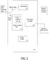
Figure 3 is PoE supporting PSE having a field replaceable surge protection, in accordance with one embodiment; -
Figure 4 is PoE supporting PSE having a field replaceable surge protection, in accordance with one embodiment; and -
Figure 5 is PoE supporting PSE having a field replaceable surge protection, in accordance with one embodiment. - In one embodiment as illustrated in
Figure 3 , the present arrangement provides aremote PSE 10 intended to be used in a PoE type environment. - In this example,
PSE 10 is connected to a composite optical/power cable 12 supporting bothoptical fibers 14 andpower wires 16. Optical fibers are routed to atransceiver 18 for receiving the optical signals and re-formatting to a copper wire signal for transmission through to thePoE device controller 20. -
Power component 16 ofcomposite cable 12 is directed to asurge protector slot 22 and then topower module 24. Unlike the prior art,surge protector slot 22 is not embedded withinPoE device controller 20 or inpower module 24, but instead is isolated from both in an independenthardwired slot 22 with a removable and replaceablesurge protector unit 26. In the case of a surge event on thecomposite cable 12, the surge would enterPSE 10 and be collected and discharged byprotector unit 26 inslot 22 prior to damaging eitherpower module 24 orPoE device 20. Thereafter the operator may remove the usedsurge protector unit 26 and replace it in-field with a newsurge protector unit 26 without replace either one ofPoE controller 20 or power module 24 (orPSE 10 as a whole). This is a significant improvement over prior art systems with embedded surge protector like that shown inFigure 2 . - It is understood that
surge protector unit 26 may be any one of a silicon avalanche suppressor diode (SASD), a metal oxide varsitor (MOV), filters, gas tubes or combinations thereof depending on the desired level of protection, cost and PSE application (and likely types of surge events to be experienced). - In another embodiment shown in
Figure 4 , everything is essentially the same as shown inFigure 3 except that a secondsurge protector unit 36 is included in a separatesurge protector slot 32 located between remote devices andPoE controller 20 so as to protectPoE controller 20 from surge events emanating from the remote devices side of PSE 10 (as opposed to those emanating from composite cable 12).Surge protection unit 36 andsurge protector slot 32 are essentially the same asunit 26 andslot 22 except that the surge protection levels may be different depending on the intended level of protection as determined by the system architect. - In another embodiment shown in
Figure 5 , an additional length ofconductor 40 is included between surge protector units/slots 26/22, 36/32 and their protected devices, namelypower module 24 andPoE device controller 20 respectively. It is noted that this embodiment ofadditional conductor 40 may also be implemented in the arrangement ofFigure 3 (i.e. solely betweenslot 22 and power module 24). -
Additional conductor 40 may be in the form of a length of electrical conductor betweeninternal power supply 24 ofPSE 10 andsurge protector slot 22. This arrangement provides additional 'time' for the surge components to work before the surge reaches connected component (i.e. power module 24 and PoE device 20). In one embodiment,additional conductor length 40 is about three (3) feet or longer. In one example, atypical PSE 10 is a square box with the circuit boards (components) inside with all of the circuitry and components for performing all of the functions such as those described above.Additional conductor 40 could be wrapped around the inside perimeter of the box or wrapped around a cylinder or be wound into a coil. The diameter ofadditional conductor 40 could be any wire size, but the smaller it is, the more DC resistance it induces. In other arrangements, the tradeoff of using a smalleradditional conductor 40 is that it takes up less space inside thePSE 10 box. - While only certain features of the invention have been illustrated and described herein, many modifications, substitutions, changes or equivalents will now occur to those skilled in the art. It is therefore, to be understood that this application is intended to cover all such modifications and changes that fall within the true spirit of the invention.
Claims (7)
- A Power Sourcing Equipment (10) for remote powering of PoE equipment comprising:a transceiver (18) for receiving an optical signal;a power module (24) for receiving a power input;a PoE device (20) for receiving and converting said optical signal and said power input and controlling at least one remote device; anda surge protector slot (22) with a removable and field replaceable surge protector unit (26),wherein said removable field replaceable surge protector unit (26), after triggering by a surge event, is removable and replaceable with a new field replaceable surge protector unit allowing for continued surge protection without replacing the entire power sourcing equipment.
- The Power sourcing equipment as claimed in claim 1, wherein said surge protector slot (22) with a removable and field replaceable surge protector unit (26) are between said power module (24) and a power component of an optical power composite cable.
- The Power sourcing equipment as claimed in claim 1, further comprising a second surge protector slot (32) with a removable and field replaceable surge protector unit (36).
- The power sourcing equipment as claimed in claim 3, wherein said second surge protector slot (32) with a removable and field replaceable surge protector unit (36) is located between said PoE device (20) and said remote device.
- The power sourcing equipment as claimed in claim 1, wherein said field replaceable surge protector unit (26) includes surge protection equipment selected from the group consisting of: silicon avalanche suppressor diode (SASD), metal oxide varsitor (MOV), filters, gas tubes, and combinations thereof.
- The power sourcing equipment as claimed in claim 1, further comprising an additional length of conductor (40) of at least 3 feet, between said surge protector slot (22) with a removable and field replaceable surge protector unit (26) and said power module (24).
- The power souring equipment as claimed in claim 4, further comprising an additional length of conductor (40) of at least 3 feet, between said second surge protector slot (32) with a removable and field replaceable surge protector unit (38) and said PoE device (20).
Applications Claiming Priority (1)
| Application Number | Priority Date | Filing Date | Title |
|---|---|---|---|
| US16/236,558 US11018491B2 (en) | 2018-12-30 | 2018-12-30 | System for field replaceable surge protection |
Publications (2)
| Publication Number | Publication Date |
|---|---|
| EP3675417A1 true EP3675417A1 (en) | 2020-07-01 |
| EP3675417B1 EP3675417B1 (en) | 2021-12-08 |
Family
ID=69165285
Family Applications (1)
| Application Number | Title | Priority Date | Filing Date |
|---|---|---|---|
| EP19306607.3A Not-in-force EP3675417B1 (en) | 2018-12-30 | 2019-12-09 | System for field replaceable surge protection |
Country Status (2)
| Country | Link |
|---|---|
| US (1) | US11018491B2 (en) |
| EP (1) | EP3675417B1 (en) |
Citations (3)
| Publication number | Priority date | Publication date | Assignee | Title |
|---|---|---|---|---|
| WO2006130810A2 (en) * | 2005-06-02 | 2006-12-07 | Porta Systems Corporation | Protected midspan power sourcing equipment for power over ethernet applications |
| US20080037188A1 (en) * | 2006-08-11 | 2008-02-14 | A.C. Data Systems Of Idaho, Inc. | Surge suppression system for power over network cables |
| KR101426469B1 (en) * | 2012-10-22 | 2014-08-05 | 정연대 | Management system of surge voltage having surge protector |
Family Cites Families (2)
| Publication number | Priority date | Publication date | Assignee | Title |
|---|---|---|---|---|
| US6980725B1 (en) * | 2002-04-30 | 2005-12-27 | Calix Networks, Inc. | Space reuse during technology upgrade in a protection area of an outdoor enclosure |
| US7660409B1 (en) * | 2004-05-25 | 2010-02-09 | Alcatel Lucent | Multi-dwelling unit module for passive optical networks |
-
2018
- 2018-12-30 US US16/236,558 patent/US11018491B2/en active Active
-
2019
- 2019-12-09 EP EP19306607.3A patent/EP3675417B1/en not_active Not-in-force
Patent Citations (3)
| Publication number | Priority date | Publication date | Assignee | Title |
|---|---|---|---|---|
| WO2006130810A2 (en) * | 2005-06-02 | 2006-12-07 | Porta Systems Corporation | Protected midspan power sourcing equipment for power over ethernet applications |
| US20080037188A1 (en) * | 2006-08-11 | 2008-02-14 | A.C. Data Systems Of Idaho, Inc. | Surge suppression system for power over network cables |
| KR101426469B1 (en) * | 2012-10-22 | 2014-08-05 | 정연대 | Management system of surge voltage having surge protector |
Also Published As
| Publication number | Publication date |
|---|---|
| EP3675417B1 (en) | 2021-12-08 |
| US11018491B2 (en) | 2021-05-25 |
| US20200212665A1 (en) | 2020-07-02 |
Similar Documents
| Publication | Publication Date | Title |
|---|---|---|
| US9819500B2 (en) | System and method for isolating and protecting a PoE (power over ethernet) device | |
| US10826250B2 (en) | Power cord with in-line power control functionality | |
| DE102016011815B3 (en) | Control gear with staggered overvoltage and overcurrent protection for the control of intelligent light sources and devices as well as light sources with this control gear | |
| US20140143578A1 (en) | Power line communication monitor | |
| EP2645513A1 (en) | Lightning protection radio remote unit, distributed base station and lightning protection system and method thereof | |
| EP3100061B1 (en) | Neutral fault voltage detection device | |
| US20070230080A1 (en) | Environmentally hardened ethernet switch | |
| MX2011008507A (en) | Inter-networking devices for use with physical layer information. | |
| CN101320997B (en) | Power line communications system | |
| EP2779641A3 (en) | Closed circuit video monitoring system | |
| CN107615086A (en) | For system, the method and apparatus of the integrality for diagnosing electric conductor bearing system | |
| CN204464985U (en) | A kind of POE system protection circuit and POE guard system | |
| EP3675417B1 (en) | System for field replaceable surge protection | |
| KR101314733B1 (en) | Intelligent lightning management system | |
| CN208890359U (en) | Surge protection device | |
| JP6162979B2 (en) | Optical communication system for collective facilities | |
| CN102175957A (en) | Online insulation monitoring system | |
| JP2003098362A (en) | Optical communication cable termination box | |
| JP5613107B2 (en) | Overvoltage / overcurrent protection system and overvoltage / overcurrent protection method | |
| KR20150006526A (en) | An Integrated Junction box, A Multi-cable and A Marine CCTV System Comprising The Same | |
| CN202617111U (en) | Ethernet integrated controller and network system thereof | |
| WO2015005835A1 (en) | Interface arrangement between network node and radio access unit | |
| SE519029C2 (en) | Device for connecting or detaching an electro-optical converter to or from at least one optical fiber | |
| CN104393453A (en) | Lighting protection design of eight-wire RJ45 network information module | |
| CN105159416A (en) | Project management apparatus with good anti-lightning effect |
Legal Events
| Date | Code | Title | Description |
|---|---|---|---|
| PUAI | Public reference made under article 153(3) epc to a published international application that has entered the european phase |
Free format text: ORIGINAL CODE: 0009012 |
|
| STAA | Information on the status of an ep patent application or granted ep patent |
Free format text: STATUS: THE APPLICATION HAS BEEN PUBLISHED |
|
| AK | Designated contracting states |
Kind code of ref document: A1 Designated state(s): AL AT BE BG CH CY CZ DE DK EE ES FI FR GB GR HR HU IE IS IT LI LT LU LV MC MK MT NL NO PL PT RO RS SE SI SK SM TR |
|
| AX | Request for extension of the european patent |
Extension state: BA ME |
|
| RAP1 | Party data changed (applicant data changed or rights of an application transferred) |
Owner name: BERK-TEK LLC |
|
| STAA | Information on the status of an ep patent application or granted ep patent |
Free format text: STATUS: REQUEST FOR EXAMINATION WAS MADE |
|
| 17P | Request for examination filed |
Effective date: 20201224 |
|
| RBV | Designated contracting states (corrected) |
Designated state(s): AL AT BE BG CH CY CZ DE DK EE ES FI FR GB GR HR HU IE IS IT LI LT LU LV MC MK MT NL NO PL PT RO RS SE SI SK SM TR |
|
| GRAP | Despatch of communication of intention to grant a patent |
Free format text: ORIGINAL CODE: EPIDOSNIGR1 |
|
| STAA | Information on the status of an ep patent application or granted ep patent |
Free format text: STATUS: GRANT OF PATENT IS INTENDED |
|
| RIC1 | Information provided on ipc code assigned before grant |
Ipc: H04L 12/10 20060101AFI20210601BHEP Ipc: G06F 1/26 20060101ALI20210601BHEP |
|
| INTG | Intention to grant announced |
Effective date: 20210629 |
|
| GRAS | Grant fee paid |
Free format text: ORIGINAL CODE: EPIDOSNIGR3 |
|
| GRAA | (expected) grant |
Free format text: ORIGINAL CODE: 0009210 |
|
| STAA | Information on the status of an ep patent application or granted ep patent |
Free format text: STATUS: THE PATENT HAS BEEN GRANTED |
|
| AK | Designated contracting states |
Kind code of ref document: B1 Designated state(s): AL AT BE BG CH CY CZ DE DK EE ES FI FR GB GR HR HU IE IS IT LI LT LU LV MC MK MT NL NO PL PT RO RS SE SI SK SM TR |
|
| REG | Reference to a national code |
Ref country code: GB Ref legal event code: FG4D |
|
| REG | Reference to a national code |
Ref country code: AT Ref legal event code: REF Ref document number: 1454573 Country of ref document: AT Kind code of ref document: T Effective date: 20211215 Ref country code: CH Ref legal event code: EP |
|
| REG | Reference to a national code |
Ref country code: DE Ref legal event code: R096 Ref document number: 602019009917 Country of ref document: DE |
|
| REG | Reference to a national code |
Ref country code: IE Ref legal event code: FG4D |
|
| REG | Reference to a national code |
Ref country code: LT Ref legal event code: MG9D |
|
| REG | Reference to a national code |
Ref country code: NL Ref legal event code: MP Effective date: 20211208 |
|
| PG25 | Lapsed in a contracting state [announced via postgrant information from national office to epo] |
Ref country code: RS Free format text: LAPSE BECAUSE OF FAILURE TO SUBMIT A TRANSLATION OF THE DESCRIPTION OR TO PAY THE FEE WITHIN THE PRESCRIBED TIME-LIMIT Effective date: 20211208 Ref country code: LT Free format text: LAPSE BECAUSE OF FAILURE TO SUBMIT A TRANSLATION OF THE DESCRIPTION OR TO PAY THE FEE WITHIN THE PRESCRIBED TIME-LIMIT Effective date: 20211208 Ref country code: FI Free format text: LAPSE BECAUSE OF FAILURE TO SUBMIT A TRANSLATION OF THE DESCRIPTION OR TO PAY THE FEE WITHIN THE PRESCRIBED TIME-LIMIT Effective date: 20211208 Ref country code: BG Free format text: LAPSE BECAUSE OF FAILURE TO SUBMIT A TRANSLATION OF THE DESCRIPTION OR TO PAY THE FEE WITHIN THE PRESCRIBED TIME-LIMIT Effective date: 20220308 |
|
| REG | Reference to a national code |
Ref country code: AT Ref legal event code: MK05 Ref document number: 1454573 Country of ref document: AT Kind code of ref document: T Effective date: 20211208 |
|
| PG25 | Lapsed in a contracting state [announced via postgrant information from national office to epo] |
Ref country code: SE Free format text: LAPSE BECAUSE OF FAILURE TO SUBMIT A TRANSLATION OF THE DESCRIPTION OR TO PAY THE FEE WITHIN THE PRESCRIBED TIME-LIMIT Effective date: 20211208 Ref country code: NO Free format text: LAPSE BECAUSE OF FAILURE TO SUBMIT A TRANSLATION OF THE DESCRIPTION OR TO PAY THE FEE WITHIN THE PRESCRIBED TIME-LIMIT Effective date: 20220308 Ref country code: LV Free format text: LAPSE BECAUSE OF FAILURE TO SUBMIT A TRANSLATION OF THE DESCRIPTION OR TO PAY THE FEE WITHIN THE PRESCRIBED TIME-LIMIT Effective date: 20211208 Ref country code: HR Free format text: LAPSE BECAUSE OF FAILURE TO SUBMIT A TRANSLATION OF THE DESCRIPTION OR TO PAY THE FEE WITHIN THE PRESCRIBED TIME-LIMIT Effective date: 20211208 Ref country code: GR Free format text: LAPSE BECAUSE OF FAILURE TO SUBMIT A TRANSLATION OF THE DESCRIPTION OR TO PAY THE FEE WITHIN THE PRESCRIBED TIME-LIMIT Effective date: 20220309 Ref country code: ES Free format text: LAPSE BECAUSE OF FAILURE TO SUBMIT A TRANSLATION OF THE DESCRIPTION OR TO PAY THE FEE WITHIN THE PRESCRIBED TIME-LIMIT Effective date: 20211208 |
|
| PG25 | Lapsed in a contracting state [announced via postgrant information from national office to epo] |
Ref country code: NL Free format text: LAPSE BECAUSE OF FAILURE TO SUBMIT A TRANSLATION OF THE DESCRIPTION OR TO PAY THE FEE WITHIN THE PRESCRIBED TIME-LIMIT Effective date: 20211208 |
|
| REG | Reference to a national code |
Ref country code: DE Ref legal event code: R119 Ref document number: 602019009917 Country of ref document: DE |
|
| PG25 | Lapsed in a contracting state [announced via postgrant information from national office to epo] |
Ref country code: SM Free format text: LAPSE BECAUSE OF FAILURE TO SUBMIT A TRANSLATION OF THE DESCRIPTION OR TO PAY THE FEE WITHIN THE PRESCRIBED TIME-LIMIT Effective date: 20211208 Ref country code: SK Free format text: LAPSE BECAUSE OF FAILURE TO SUBMIT A TRANSLATION OF THE DESCRIPTION OR TO PAY THE FEE WITHIN THE PRESCRIBED TIME-LIMIT Effective date: 20211208 Ref country code: RO Free format text: LAPSE BECAUSE OF FAILURE TO SUBMIT A TRANSLATION OF THE DESCRIPTION OR TO PAY THE FEE WITHIN THE PRESCRIBED TIME-LIMIT Effective date: 20211208 Ref country code: PT Free format text: LAPSE BECAUSE OF FAILURE TO SUBMIT A TRANSLATION OF THE DESCRIPTION OR TO PAY THE FEE WITHIN THE PRESCRIBED TIME-LIMIT Effective date: 20220408 Ref country code: EE Free format text: LAPSE BECAUSE OF FAILURE TO SUBMIT A TRANSLATION OF THE DESCRIPTION OR TO PAY THE FEE WITHIN THE PRESCRIBED TIME-LIMIT Effective date: 20211208 Ref country code: CZ Free format text: LAPSE BECAUSE OF FAILURE TO SUBMIT A TRANSLATION OF THE DESCRIPTION OR TO PAY THE FEE WITHIN THE PRESCRIBED TIME-LIMIT Effective date: 20211208 |
|
| PG25 | Lapsed in a contracting state [announced via postgrant information from national office to epo] |
Ref country code: PL Free format text: LAPSE BECAUSE OF FAILURE TO SUBMIT A TRANSLATION OF THE DESCRIPTION OR TO PAY THE FEE WITHIN THE PRESCRIBED TIME-LIMIT Effective date: 20211208 Ref country code: AT Free format text: LAPSE BECAUSE OF FAILURE TO SUBMIT A TRANSLATION OF THE DESCRIPTION OR TO PAY THE FEE WITHIN THE PRESCRIBED TIME-LIMIT Effective date: 20211208 |
|
| REG | Reference to a national code |
Ref country code: BE Ref legal event code: MM Effective date: 20211231 |
|
| PG25 | Lapsed in a contracting state [announced via postgrant information from national office to epo] |
Ref country code: MC Free format text: LAPSE BECAUSE OF FAILURE TO SUBMIT A TRANSLATION OF THE DESCRIPTION OR TO PAY THE FEE WITHIN THE PRESCRIBED TIME-LIMIT Effective date: 20211208 Ref country code: IS Free format text: LAPSE BECAUSE OF FAILURE TO SUBMIT A TRANSLATION OF THE DESCRIPTION OR TO PAY THE FEE WITHIN THE PRESCRIBED TIME-LIMIT Effective date: 20220408 |
|
| PLBE | No opposition filed within time limit |
Free format text: ORIGINAL CODE: 0009261 |
|
| STAA | Information on the status of an ep patent application or granted ep patent |
Free format text: STATUS: NO OPPOSITION FILED WITHIN TIME LIMIT |
|
| PG25 | Lapsed in a contracting state [announced via postgrant information from national office to epo] |
Ref country code: LU Free format text: LAPSE BECAUSE OF NON-PAYMENT OF DUE FEES Effective date: 20211209 Ref country code: IE Free format text: LAPSE BECAUSE OF NON-PAYMENT OF DUE FEES Effective date: 20211209 Ref country code: DK Free format text: LAPSE BECAUSE OF FAILURE TO SUBMIT A TRANSLATION OF THE DESCRIPTION OR TO PAY THE FEE WITHIN THE PRESCRIBED TIME-LIMIT Effective date: 20211208 Ref country code: DE Free format text: LAPSE BECAUSE OF NON-PAYMENT OF DUE FEES Effective date: 20220701 Ref country code: AL Free format text: LAPSE BECAUSE OF FAILURE TO SUBMIT A TRANSLATION OF THE DESCRIPTION OR TO PAY THE FEE WITHIN THE PRESCRIBED TIME-LIMIT Effective date: 20211208 |
|
| 26N | No opposition filed |
Effective date: 20220909 |
|
| PG25 | Lapsed in a contracting state [announced via postgrant information from national office to epo] |
Ref country code: SI Free format text: LAPSE BECAUSE OF FAILURE TO SUBMIT A TRANSLATION OF THE DESCRIPTION OR TO PAY THE FEE WITHIN THE PRESCRIBED TIME-LIMIT Effective date: 20211208 Ref country code: BE Free format text: LAPSE BECAUSE OF NON-PAYMENT OF DUE FEES Effective date: 20211231 |
|
| PG25 | Lapsed in a contracting state [announced via postgrant information from national office to epo] |
Ref country code: FR Free format text: LAPSE BECAUSE OF NON-PAYMENT OF DUE FEES Effective date: 20220208 |
|
| PG25 | Lapsed in a contracting state [announced via postgrant information from national office to epo] |
Ref country code: IT Free format text: LAPSE BECAUSE OF FAILURE TO SUBMIT A TRANSLATION OF THE DESCRIPTION OR TO PAY THE FEE WITHIN THE PRESCRIBED TIME-LIMIT Effective date: 20211208 |
|
| PG25 | Lapsed in a contracting state [announced via postgrant information from national office to epo] |
Ref country code: CY Free format text: LAPSE BECAUSE OF FAILURE TO SUBMIT A TRANSLATION OF THE DESCRIPTION OR TO PAY THE FEE WITHIN THE PRESCRIBED TIME-LIMIT Effective date: 20211208 |
|
| PG25 | Lapsed in a contracting state [announced via postgrant information from national office to epo] |
Ref country code: HU Free format text: LAPSE BECAUSE OF FAILURE TO SUBMIT A TRANSLATION OF THE DESCRIPTION OR TO PAY THE FEE WITHIN THE PRESCRIBED TIME-LIMIT; INVALID AB INITIO Effective date: 20191209 |
|
| REG | Reference to a national code |
Ref country code: CH Ref legal event code: PL |
|
| PG25 | Lapsed in a contracting state [announced via postgrant information from national office to epo] |
Ref country code: LI Free format text: LAPSE BECAUSE OF NON-PAYMENT OF DUE FEES Effective date: 20221231 Ref country code: CH Free format text: LAPSE BECAUSE OF NON-PAYMENT OF DUE FEES Effective date: 20221231 |
|
| PG25 | Lapsed in a contracting state [announced via postgrant information from national office to epo] |
Ref country code: MK Free format text: LAPSE BECAUSE OF FAILURE TO SUBMIT A TRANSLATION OF THE DESCRIPTION OR TO PAY THE FEE WITHIN THE PRESCRIBED TIME-LIMIT Effective date: 20211208 |
|
| GBPC | Gb: european patent ceased through non-payment of renewal fee |
Effective date: 20231209 |
|
| PG25 | Lapsed in a contracting state [announced via postgrant information from national office to epo] |
Ref country code: MT Free format text: LAPSE BECAUSE OF FAILURE TO SUBMIT A TRANSLATION OF THE DESCRIPTION OR TO PAY THE FEE WITHIN THE PRESCRIBED TIME-LIMIT Effective date: 20211208 |
|
| PG25 | Lapsed in a contracting state [announced via postgrant information from national office to epo] |
Ref country code: GB Free format text: LAPSE BECAUSE OF NON-PAYMENT OF DUE FEES Effective date: 20231209 |
|
| PG25 | Lapsed in a contracting state [announced via postgrant information from national office to epo] |
Ref country code: GB Free format text: LAPSE BECAUSE OF NON-PAYMENT OF DUE FEES Effective date: 20231209 |
|
| PG25 | Lapsed in a contracting state [announced via postgrant information from national office to epo] |
Ref country code: TR Free format text: LAPSE BECAUSE OF FAILURE TO SUBMIT A TRANSLATION OF THE DESCRIPTION OR TO PAY THE FEE WITHIN THE PRESCRIBED TIME-LIMIT Effective date: 20211208 |