EP3675341A1 - Dc-dc converter for electric vehicle - Google Patents
Dc-dc converter for electric vehicle Download PDFInfo
- Publication number
- EP3675341A1 EP3675341A1 EP19219801.8A EP19219801A EP3675341A1 EP 3675341 A1 EP3675341 A1 EP 3675341A1 EP 19219801 A EP19219801 A EP 19219801A EP 3675341 A1 EP3675341 A1 EP 3675341A1
- Authority
- EP
- European Patent Office
- Prior art keywords
- converter
- inductor
- current
- switch
- transformer
- Prior art date
- Legal status (The legal status is an assumption and is not a legal conclusion. Google has not performed a legal analysis and makes no representation as to the accuracy of the status listed.)
- Withdrawn
Links
Images


Classifications
-
- B—PERFORMING OPERATIONS; TRANSPORTING
- B60—VEHICLES IN GENERAL
- B60L—PROPULSION OF ELECTRICALLY-PROPELLED VEHICLES; SUPPLYING ELECTRIC POWER FOR AUXILIARY EQUIPMENT OF ELECTRICALLY-PROPELLED VEHICLES; ELECTRODYNAMIC BRAKE SYSTEMS FOR VEHICLES IN GENERAL; MAGNETIC SUSPENSION OR LEVITATION FOR VEHICLES; MONITORING OPERATING VARIABLES OF ELECTRICALLY-PROPELLED VEHICLES; ELECTRIC SAFETY DEVICES FOR ELECTRICALLY-PROPELLED VEHICLES
- B60L53/00—Methods of charging batteries, specially adapted for electric vehicles; Charging stations or on-board charging equipment therefor; Exchange of energy storage elements in electric vehicles
- B60L53/60—Monitoring or controlling charging stations
- B60L53/62—Monitoring or controlling charging stations in response to charging parameters, e.g. current, voltage or electrical charge
-
- H—ELECTRICITY
- H02—GENERATION; CONVERSION OR DISTRIBUTION OF ELECTRIC POWER
- H02M—APPARATUS FOR CONVERSION BETWEEN AC AND AC, BETWEEN AC AND DC, OR BETWEEN DC AND DC, AND FOR USE WITH MAINS OR SIMILAR POWER SUPPLY SYSTEMS; CONVERSION OF DC OR AC INPUT POWER INTO SURGE OUTPUT POWER; CONTROL OR REGULATION THEREOF
- H02M3/00—Conversion of DC power input into DC power output
- H02M3/22—Conversion of DC power input into DC power output with intermediate conversion into AC
- H02M3/24—Conversion of DC power input into DC power output with intermediate conversion into AC by static converters
- H02M3/28—Conversion of DC power input into DC power output with intermediate conversion into AC by static converters using discharge tubes with control electrode or semiconductor devices with control electrode to produce the intermediate AC
- H02M3/325—Conversion of DC power input into DC power output with intermediate conversion into AC by static converters using discharge tubes with control electrode or semiconductor devices with control electrode to produce the intermediate AC using devices of a triode or a transistor type requiring continuous application of a control signal
- H02M3/335—Conversion of DC power input into DC power output with intermediate conversion into AC by static converters using discharge tubes with control electrode or semiconductor devices with control electrode to produce the intermediate AC using devices of a triode or a transistor type requiring continuous application of a control signal using semiconductor devices only
- H02M3/33569—Conversion of DC power input into DC power output with intermediate conversion into AC by static converters using discharge tubes with control electrode or semiconductor devices with control electrode to produce the intermediate AC using devices of a triode or a transistor type requiring continuous application of a control signal using semiconductor devices only having several active switching elements
- H02M3/33576—Conversion of DC power input into DC power output with intermediate conversion into AC by static converters using discharge tubes with control electrode or semiconductor devices with control electrode to produce the intermediate AC using devices of a triode or a transistor type requiring continuous application of a control signal using semiconductor devices only having several active switching elements having at least one active switching element at the secondary side of an isolation transformer
- H02M3/33584—Bidirectional converters
-
- H—ELECTRICITY
- H02—GENERATION; CONVERSION OR DISTRIBUTION OF ELECTRIC POWER
- H02M—APPARATUS FOR CONVERSION BETWEEN AC AND AC, BETWEEN AC AND DC, OR BETWEEN DC AND DC, AND FOR USE WITH MAINS OR SIMILAR POWER SUPPLY SYSTEMS; CONVERSION OF DC OR AC INPUT POWER INTO SURGE OUTPUT POWER; CONTROL OR REGULATION THEREOF
- H02M3/00—Conversion of DC power input into DC power output
- H02M3/22—Conversion of DC power input into DC power output with intermediate conversion into AC
- H02M3/24—Conversion of DC power input into DC power output with intermediate conversion into AC by static converters
-
- B—PERFORMING OPERATIONS; TRANSPORTING
- B60—VEHICLES IN GENERAL
- B60L—PROPULSION OF ELECTRICALLY-PROPELLED VEHICLES; SUPPLYING ELECTRIC POWER FOR AUXILIARY EQUIPMENT OF ELECTRICALLY-PROPELLED VEHICLES; ELECTRODYNAMIC BRAKE SYSTEMS FOR VEHICLES IN GENERAL; MAGNETIC SUSPENSION OR LEVITATION FOR VEHICLES; MONITORING OPERATING VARIABLES OF ELECTRICALLY-PROPELLED VEHICLES; ELECTRIC SAFETY DEVICES FOR ELECTRICALLY-PROPELLED VEHICLES
- B60L53/00—Methods of charging batteries, specially adapted for electric vehicles; Charging stations or on-board charging equipment therefor; Exchange of energy storage elements in electric vehicles
- B60L53/20—Methods of charging batteries, specially adapted for electric vehicles; Charging stations or on-board charging equipment therefor; Exchange of energy storage elements in electric vehicles characterised by converters located in the vehicle
- B60L53/22—Constructional details or arrangements of charging converters specially adapted for charging electric vehicles
-
- H—ELECTRICITY
- H02—GENERATION; CONVERSION OR DISTRIBUTION OF ELECTRIC POWER
- H02J—ELECTRIC POWER NETWORKS; CIRCUIT ARRANGEMENTS OR SYSTEMS FOR SUPPLYING OR DISTRIBUTING ELECTRIC POWER; SYSTEMS FOR STORING ELECTRIC ENERGY
- H02J1/00—Circuit arrangements for DC mains or DC distribution networks
- H02J1/002—Circuit arrangements for DC mains or DC distribution networks using intermediate DC-AC-DC conversion
-
- H—ELECTRICITY
- H02—GENERATION; CONVERSION OR DISTRIBUTION OF ELECTRIC POWER
- H02J—ELECTRIC POWER NETWORKS; CIRCUIT ARRANGEMENTS OR SYSTEMS FOR SUPPLYING OR DISTRIBUTING ELECTRIC POWER; SYSTEMS FOR STORING ELECTRIC ENERGY
- H02J7/00—Circuit arrangements for charging or discharging batteries or for supplying loads from batteries
- H02J7/02—Circuit arrangements for charging or discharging batteries or for supplying loads from batteries for charging batteries from AC mains by converters
-
- H—ELECTRICITY
- H02—GENERATION; CONVERSION OR DISTRIBUTION OF ELECTRIC POWER
- H02J—ELECTRIC POWER NETWORKS; CIRCUIT ARRANGEMENTS OR SYSTEMS FOR SUPPLYING OR DISTRIBUTING ELECTRIC POWER; SYSTEMS FOR STORING ELECTRIC ENERGY
- H02J7/00—Circuit arrangements for charging or discharging batteries or for supplying loads from batteries
- H02J7/02—Circuit arrangements for charging or discharging batteries or for supplying loads from batteries for charging batteries from AC mains by converters
- H02J7/04—Regulation of charging current or voltage
- H02J7/06—Regulation of charging current or voltage using discharge tubes or semiconductor devices
- H02J7/08—Regulation of charging current or voltage using discharge tubes or semiconductor devices using discharge tubes only
-
- H—ELECTRICITY
- H02—GENERATION; CONVERSION OR DISTRIBUTION OF ELECTRIC POWER
- H02J—ELECTRIC POWER NETWORKS; CIRCUIT ARRANGEMENTS OR SYSTEMS FOR SUPPLYING OR DISTRIBUTING ELECTRIC POWER; SYSTEMS FOR STORING ELECTRIC ENERGY
- H02J7/00—Circuit arrangements for charging or discharging batteries or for supplying loads from batteries
- H02J7/50—Circuit arrangements for charging or discharging batteries or for supplying loads from batteries acting upon multiple batteries simultaneously or sequentially
-
- H—ELECTRICITY
- H02—GENERATION; CONVERSION OR DISTRIBUTION OF ELECTRIC POWER
- H02J—ELECTRIC POWER NETWORKS; CIRCUIT ARRANGEMENTS OR SYSTEMS FOR SUPPLYING OR DISTRIBUTING ELECTRIC POWER; SYSTEMS FOR STORING ELECTRIC ENERGY
- H02J7/00—Circuit arrangements for charging or discharging batteries or for supplying loads from batteries
- H02J7/865—Battery or charger load switching, e.g. concurrent charging and load supply
-
- H—ELECTRICITY
- H02—GENERATION; CONVERSION OR DISTRIBUTION OF ELECTRIC POWER
- H02J—ELECTRIC POWER NETWORKS; CIRCUIT ARRANGEMENTS OR SYSTEMS FOR SUPPLYING OR DISTRIBUTING ELECTRIC POWER; SYSTEMS FOR STORING ELECTRIC ENERGY
- H02J7/00—Circuit arrangements for charging or discharging batteries or for supplying loads from batteries
- H02J7/90—Regulation of charging or discharging current or voltage
- H02J7/933—Regulation of charging or discharging current or voltage the cycle being controlled or terminated in response to electric parameters
-
- H—ELECTRICITY
- H02—GENERATION; CONVERSION OR DISTRIBUTION OF ELECTRIC POWER
- H02M—APPARATUS FOR CONVERSION BETWEEN AC AND AC, BETWEEN AC AND DC, OR BETWEEN DC AND DC, AND FOR USE WITH MAINS OR SIMILAR POWER SUPPLY SYSTEMS; CONVERSION OF DC OR AC INPUT POWER INTO SURGE OUTPUT POWER; CONTROL OR REGULATION THEREOF
- H02M1/00—Details of apparatus for conversion
- H02M1/42—Circuits or arrangements for compensating for or adjusting power factor in converters or inverters
-
- H—ELECTRICITY
- H02—GENERATION; CONVERSION OR DISTRIBUTION OF ELECTRIC POWER
- H02M—APPARATUS FOR CONVERSION BETWEEN AC AND AC, BETWEEN AC AND DC, OR BETWEEN DC AND DC, AND FOR USE WITH MAINS OR SIMILAR POWER SUPPLY SYSTEMS; CONVERSION OF DC OR AC INPUT POWER INTO SURGE OUTPUT POWER; CONTROL OR REGULATION THEREOF
- H02M1/00—Details of apparatus for conversion
- H02M1/42—Circuits or arrangements for compensating for or adjusting power factor in converters or inverters
- H02M1/4208—Arrangements for improving power factor of AC input
- H02M1/4241—Arrangements for improving power factor of AC input using a resonant converter
-
- B—PERFORMING OPERATIONS; TRANSPORTING
- B60—VEHICLES IN GENERAL
- B60L—PROPULSION OF ELECTRICALLY-PROPELLED VEHICLES; SUPPLYING ELECTRIC POWER FOR AUXILIARY EQUIPMENT OF ELECTRICALLY-PROPELLED VEHICLES; ELECTRODYNAMIC BRAKE SYSTEMS FOR VEHICLES IN GENERAL; MAGNETIC SUSPENSION OR LEVITATION FOR VEHICLES; MONITORING OPERATING VARIABLES OF ELECTRICALLY-PROPELLED VEHICLES; ELECTRIC SAFETY DEVICES FOR ELECTRICALLY-PROPELLED VEHICLES
- B60L2210/00—Converter types
- B60L2210/10—DC to DC converters
-
- B—PERFORMING OPERATIONS; TRANSPORTING
- B60—VEHICLES IN GENERAL
- B60L—PROPULSION OF ELECTRICALLY-PROPELLED VEHICLES; SUPPLYING ELECTRIC POWER FOR AUXILIARY EQUIPMENT OF ELECTRICALLY-PROPELLED VEHICLES; ELECTRODYNAMIC BRAKE SYSTEMS FOR VEHICLES IN GENERAL; MAGNETIC SUSPENSION OR LEVITATION FOR VEHICLES; MONITORING OPERATING VARIABLES OF ELECTRICALLY-PROPELLED VEHICLES; ELECTRIC SAFETY DEVICES FOR ELECTRICALLY-PROPELLED VEHICLES
- B60L2210/00—Converter types
- B60L2210/20—AC to AC converters
- B60L2210/22—AC to AC converters without intermediate conversion to DC
-
- B—PERFORMING OPERATIONS; TRANSPORTING
- B60—VEHICLES IN GENERAL
- B60L—PROPULSION OF ELECTRICALLY-PROPELLED VEHICLES; SUPPLYING ELECTRIC POWER FOR AUXILIARY EQUIPMENT OF ELECTRICALLY-PROPELLED VEHICLES; ELECTRODYNAMIC BRAKE SYSTEMS FOR VEHICLES IN GENERAL; MAGNETIC SUSPENSION OR LEVITATION FOR VEHICLES; MONITORING OPERATING VARIABLES OF ELECTRICALLY-PROPELLED VEHICLES; ELECTRIC SAFETY DEVICES FOR ELECTRICALLY-PROPELLED VEHICLES
- B60L2210/00—Converter types
- B60L2210/30—AC to DC converters
-
- B—PERFORMING OPERATIONS; TRANSPORTING
- B60—VEHICLES IN GENERAL
- B60L—PROPULSION OF ELECTRICALLY-PROPELLED VEHICLES; SUPPLYING ELECTRIC POWER FOR AUXILIARY EQUIPMENT OF ELECTRICALLY-PROPELLED VEHICLES; ELECTRODYNAMIC BRAKE SYSTEMS FOR VEHICLES IN GENERAL; MAGNETIC SUSPENSION OR LEVITATION FOR VEHICLES; MONITORING OPERATING VARIABLES OF ELECTRICALLY-PROPELLED VEHICLES; ELECTRIC SAFETY DEVICES FOR ELECTRICALLY-PROPELLED VEHICLES
- B60L2210/00—Converter types
- B60L2210/40—DC to AC converters
- B60L2210/44—Current source inverters
-
- B—PERFORMING OPERATIONS; TRANSPORTING
- B60—VEHICLES IN GENERAL
- B60Y—INDEXING SCHEME RELATING TO ASPECTS CROSS-CUTTING VEHICLE TECHNOLOGY
- B60Y2200/00—Type of vehicle
- B60Y2200/90—Vehicles comprising electric prime movers
- B60Y2200/91—Electric vehicles
-
- Y—GENERAL TAGGING OF NEW TECHNOLOGICAL DEVELOPMENTS; GENERAL TAGGING OF CROSS-SECTIONAL TECHNOLOGIES SPANNING OVER SEVERAL SECTIONS OF THE IPC; TECHNICAL SUBJECTS COVERED BY FORMER USPC CROSS-REFERENCE ART COLLECTIONS [XRACs] AND DIGESTS
- Y02—TECHNOLOGIES OR APPLICATIONS FOR MITIGATION OR ADAPTATION AGAINST CLIMATE CHANGE
- Y02T—CLIMATE CHANGE MITIGATION TECHNOLOGIES RELATED TO TRANSPORTATION
- Y02T10/00—Road transport of goods or passengers
- Y02T10/60—Other road transportation technologies with climate change mitigation effect
- Y02T10/70—Energy storage systems for electromobility, e.g. batteries
-
- Y—GENERAL TAGGING OF NEW TECHNOLOGICAL DEVELOPMENTS; GENERAL TAGGING OF CROSS-SECTIONAL TECHNOLOGIES SPANNING OVER SEVERAL SECTIONS OF THE IPC; TECHNICAL SUBJECTS COVERED BY FORMER USPC CROSS-REFERENCE ART COLLECTIONS [XRACs] AND DIGESTS
- Y02—TECHNOLOGIES OR APPLICATIONS FOR MITIGATION OR ADAPTATION AGAINST CLIMATE CHANGE
- Y02T—CLIMATE CHANGE MITIGATION TECHNOLOGIES RELATED TO TRANSPORTATION
- Y02T10/00—Road transport of goods or passengers
- Y02T10/60—Other road transportation technologies with climate change mitigation effect
- Y02T10/7072—Electromobility specific charging systems or methods for batteries, ultracapacitors, supercapacitors or double-layer capacitors
-
- Y—GENERAL TAGGING OF NEW TECHNOLOGICAL DEVELOPMENTS; GENERAL TAGGING OF CROSS-SECTIONAL TECHNOLOGIES SPANNING OVER SEVERAL SECTIONS OF THE IPC; TECHNICAL SUBJECTS COVERED BY FORMER USPC CROSS-REFERENCE ART COLLECTIONS [XRACs] AND DIGESTS
- Y02—TECHNOLOGIES OR APPLICATIONS FOR MITIGATION OR ADAPTATION AGAINST CLIMATE CHANGE
- Y02T—CLIMATE CHANGE MITIGATION TECHNOLOGIES RELATED TO TRANSPORTATION
- Y02T10/00—Road transport of goods or passengers
- Y02T10/60—Other road transportation technologies with climate change mitigation effect
- Y02T10/72—Electric energy management in electromobility
-
- Y—GENERAL TAGGING OF NEW TECHNOLOGICAL DEVELOPMENTS; GENERAL TAGGING OF CROSS-SECTIONAL TECHNOLOGIES SPANNING OVER SEVERAL SECTIONS OF THE IPC; TECHNICAL SUBJECTS COVERED BY FORMER USPC CROSS-REFERENCE ART COLLECTIONS [XRACs] AND DIGESTS
- Y02—TECHNOLOGIES OR APPLICATIONS FOR MITIGATION OR ADAPTATION AGAINST CLIMATE CHANGE
- Y02T—CLIMATE CHANGE MITIGATION TECHNOLOGIES RELATED TO TRANSPORTATION
- Y02T10/00—Road transport of goods or passengers
- Y02T10/80—Technologies aiming to reduce greenhouse gasses emissions common to all road transportation technologies
- Y02T10/92—Energy efficient charging or discharging systems for batteries, ultracapacitors, supercapacitors or double-layer capacitors specially adapted for vehicles
-
- Y—GENERAL TAGGING OF NEW TECHNOLOGICAL DEVELOPMENTS; GENERAL TAGGING OF CROSS-SECTIONAL TECHNOLOGIES SPANNING OVER SEVERAL SECTIONS OF THE IPC; TECHNICAL SUBJECTS COVERED BY FORMER USPC CROSS-REFERENCE ART COLLECTIONS [XRACs] AND DIGESTS
- Y02—TECHNOLOGIES OR APPLICATIONS FOR MITIGATION OR ADAPTATION AGAINST CLIMATE CHANGE
- Y02T—CLIMATE CHANGE MITIGATION TECHNOLOGIES RELATED TO TRANSPORTATION
- Y02T90/00—Enabling technologies or technologies with a potential or indirect contribution to GHG emissions mitigation
- Y02T90/10—Technologies relating to charging of electric vehicles
- Y02T90/12—Electric charging stations
-
- Y—GENERAL TAGGING OF NEW TECHNOLOGICAL DEVELOPMENTS; GENERAL TAGGING OF CROSS-SECTIONAL TECHNOLOGIES SPANNING OVER SEVERAL SECTIONS OF THE IPC; TECHNICAL SUBJECTS COVERED BY FORMER USPC CROSS-REFERENCE ART COLLECTIONS [XRACs] AND DIGESTS
- Y02—TECHNOLOGIES OR APPLICATIONS FOR MITIGATION OR ADAPTATION AGAINST CLIMATE CHANGE
- Y02T—CLIMATE CHANGE MITIGATION TECHNOLOGIES RELATED TO TRANSPORTATION
- Y02T90/00—Enabling technologies or technologies with a potential or indirect contribution to GHG emissions mitigation
- Y02T90/10—Technologies relating to charging of electric vehicles
- Y02T90/14—Plug-in electric vehicles
Definitions
- the resonant tank is configured such that the auxiliary inductor and the first inductor are connected in parallel to each other according to whether the at least one switch is closed or not, to generate an inductance allowing the transformation unit to transform the alternating current converted in the first conversion unit into the alternating current having the charging voltage for the main battery.
- an electric vehicle can use one DC-DC converter as a resonant converter or a PWM converter, thereby using a space inside the electric vehicle more efficiently.
- some implementations of the present disclosure effectively blocks an inflow of the reflection voltage that may occur during the discharge of the main battery, thereby preventing a leakage current generated when the DC-DC converter operates as a PWM converter and preventing burnout of elements due to voltage stress or current stress.
- the transformation unit 230 can operate to transform the input AC current into a current according to an operation voltage of an auxiliary battery to supply or charge power for the additional devices or various additional devices provided in the electric vehicle. For example, when the operating voltage of the additional device and the auxiliary battery is 12 V, the transformation unit 230 can operate to transform the AC current of 48 V into an AC current of 12 V and output the transformed AC current to the third current conversion unit 260.
- the second current conversion unit 240, the transformation unit 230, and the third current conversion unit 260 may be connected (290) in the DC-DC converter so as to transform the current supplied from the main battery 250 and to supply the transformed current to the auxiliary battery 270. That is, when power is applied from the main battery 250, the DC-DC converter may operate as a PWM converter.
- Diagram (b) in FIG. 2 illustrates an example circuit structure of the resonant tank 220 and the transformation unit 230 in the DC-DC converter according to an embodiment of the present disclosure.
- the resonant tank 220 may include a resonant inductor 221 and a capacitor 222.
- the first inductor 232 of the transformation unit 230 may include an auxiliary inductor 225 such that ends of the auxiliary inductor 225 are connected to ends of the first inductor 232, respectively. That is, the first inductor 232 and the auxiliary inductor 225 may be connected in parallel to each other, and accordingly the inductance value required by the resonant converter may be generated in accordance with the parallel connection of the first inductor 232 and the auxiliary inductor 225 as shown in Equation 1 below.
- L 1 ⁇ Le L 1 ⁇ Le L 1 + Le
- an inductance of the first inductor 232 (first inductance)
- an inductance of the second inductor 233 (second inductance) may be determined.
- a side supplying a current and a side receiving a current may be changed at the transformation unit 230.
- the side supplying the current may be the second inductor 233 and the side receiving the current may be the third inductor 234, 235.
- the transformation unit 230 can operate as a PWM converter transforming the supplied current by the second inductor 233 and the third inductor 234, 235, when the main battery 250 is discharged. Therefore, the greater the size of the third inductance is, the more the transformation unit 230 operates efficiently. On the other hand, for the resonant converter that transforms a current input from a commercial power by the first inductor 232 and the second inductor 233, the size of the first inductor 232 may be limited because a specific inductance value is required.
- FIG. 3 show diagrams (a) and (b) to illustrate respective current flows when charging and discharging the main battery 250 in the DC-DC converter according to an embodiment of the present disclosure having the resonance tank 220 and the transformation unit 230.
- Diagram (a) of FIG. 3 illustrates an example process in which a PFC converts an AC current of commercial power source into a DC current and inputs the same to the DC-DC converter according to an embodiment of the present disclosure.
- the input current may be input 300 to the transformation unit 230 through the first current conversion unit 210 and the resonant tank 220, and the current transformed by the transformation unit 230 may be supplied 310 to the main battery 250 through the second current conversion unit 240.
- FIG. 4 illustrates examples in which a switch unit 400 is provided between the first current conversion unit 210 and the transformation unit 230.
- the switch unit 400 may be provided between the first current conversion unit 210 and the resonant tank 220 (as illustrated in Diagram (a) of FIG. 4 ), or between the resonant tank 220 and the transformation unit 230 (as illustrated in Diagram (b) of FIG. 4 ).
- the switch unit 400 may disconnect the circuit by opening the circuit while the power is supplied from the main battery 250 to prevent the reflection current supplied from the transformation unit 230 from flowing in.
- the converted DC current 200 may be converted into an AC current by the first DC-AC conversion unit 600.
- the current converted in the first DC-AC conversion unit 600 may vary in frequency by the resonant tank 601, and the AC current with the varied frequency may be transformed into a voltage to charge the main battery 250 by the first transformation unit 230.
- the transformed AC current may be input to the first AC-DC conversion unit 604, converted into DC current, and the converted DC current may be supplied to the main battery 250 to charge the main battery 250.
- the DC-DC converter according to the embodiment of the present disclosure may be provided only with the first current conversion unit 210, the resonant tank 220, the transformation unit 230, the second current conversion unit 240 and the third current conversion unit 260. Accordingly, in the DC-DC converter according to the embodiment of the present disclosure, the transformation units and the current conversion units can be further reduced in number, and an inner space of the electric vehicle required to install the DC-DC converter may be reduced. As a result, the inner space of the electric vehicle can be used more efficiently.
Landscapes
- Engineering & Computer Science (AREA)
- Power Engineering (AREA)
- Transportation (AREA)
- Mechanical Engineering (AREA)
- Dc-Dc Converters (AREA)
- Charge And Discharge Circuits For Batteries Or The Like (AREA)
Abstract
Description
- The present disclosure relates to a DC-DC converter used in an electric vehicle.
- In general, an electric vehicle may refer to a vehicle which is driven by using electric energy charged from a commercial power source. The electric vehicle may include a main battery charged with power from the commercial power source, and a plurality of vehicle devices operated by the main battery.
- A current supplied from a commercial power source to charge the electric vehicle typically has a very high voltage for fast charging. Accordingly, the electric vehicle transforms the current of the commercial power source into a charging voltage for the main battery, and inputs the transformed charging current into the main battery so that the main battery is charged. To this end, the electric vehicle requires a DC-DC converter that converts an input DC current into a DC current having a different voltage. For example, a resonant converter that converts power in a manner of varying a frequency is mainly used.
- Meanwhile, power charged in the main battery may be supplied as a power source to various additional devices provided in the electric vehicle. However, the main battery supplies a voltage of 48 V to drive the electric vehicle, while the additional devices of the electric vehicle typically use a current of a voltage level of 12 V. Therefore, an additional DC-DC converter is required in order to use the power of the main battery as the power source for the additional devices. And in such case that a transformation of a voltage level is not made in a wide range, a pulse width modulation (PWM) converter of a PWM method in which a current is converted according to a time that power is transferred at a fixed frequency is mainly used.
- Typically a DC current cannot be transformed. Therefore, the DC-DC converter has a configuration to convert an input direct current (first DC) 100 into alternating current (AC) for transformation, transform the AC current, and converts the transformed AC current into a DC current again. Therefore, as illustrated in
FIG. 1 , typically a DC-DC converter may include a firstcurrent conversion unit 110 converting an input DC current (first DC) 100 into an AC current, atransformation unit 120 transforming the AC current converted in the firstcurrent conversion unit 110 into an AC current of another voltage level, and a secondcurrent conversion unit 130 converting the AC current transformed in thetransformation unit 120 into a DC current (second DC) 150 again. - Because, as described above, converters are configured and used to convert power in different ways according to the range of the voltage to be transformed, an electric vehicle typically uses a resonant converter and a PWM converter respectively connected to a main battery. Therefore, the resonant converter and the PWM converter requires their own installation spaces in an internal device of the electric vehicle, which makes it difficult to efficiently use the internal space of the electric vehicle.
- An aspect of the present disclosure provides a DC-DC converter that can employ both a resonance type power conversion and a PWM type power conversion.
- Another aspect of the present disclosure provides a DC-DC converter that can be used as a resonant converter while a main battery is being charged, and used as a PWM converter while the main battery is being discharged, by changing inductance characteristics.
- In order to achieve these and other advantages and in accordance with the purpose of this specification, as embodied and broadly described herein, there is provided a DC-DC converter including a first conversion unit configured to receive a direct current converted from a commercial alternating current and convert the received direct current into an alternating current, a resonant tank having a resonant inductor and a capacitor and configured to convert a frequency of a current input from the first conversion unit, a second conversion unit configured to convert an alternating current having a charging voltage for a main battery of an electric vehicle into a direct current for charging the main battery when the alternating current is input, or to convert a direct current into an alternating current when the direct current is input from the main battery, a third conversion unit configured to receive an alternating current transformed into a current having a specific voltage and convert the received alternating current into a direct current to be supplied to devices provided in the electric vehicle, and a transformation unit having one side connected with the resonant tank and the third conversion unit and another side connected with the second conversion unit, and configured to transform an alternating current with a converted frequency into an alternating current having a charging voltage for the main battery so as to output the transformed alternating current to the second conversion unit when the alternating current with the converted frequency is input, and transform an alternating current converted in the second conversion unit into the alternating current having the specific voltage so as to output the transformed alternating current to the third conversion unit when the alternating current converted in the second conversion unit is input.
- In an embodiment, the transformation unit includes an insulator, a first inductor and a third inductor provided at one side of the insulator, the first inductor connected to the first conversion unit, and the third inductor connected to the third conversion unit, and a second inductor provided at another side of the insulator and connected to the second conversion unit, wherein the transformation unit, when the alternating current converted in the first conversion unit is input through the first inductor, transforms the input alternating current into the alternating current having the charging voltage for the main battery according to a turn ratio between the first inductor and the second inductor, and wherein the transformation unit, when the alternating current converted in the second conversion unit is input through the second inductor, transforms the input alternating current into the current having the specific voltage according to a turn ratio between the second inductor and the third inductor.
- In an embodiment, an inductance of the second inductor is determined according to an inductance of the first inductor, and an inductance of the third inductor is determined according to the inductance of the second inductor.
- In an embodiment, the third inductor is configured in which a plurality of inductors is connected in series.
- In an embodiment, the resonant tank includes a resonant inductor, an auxiliary inductor having both ends connected to both ends of the first inductor of the transformation unit, respectively, and at least one switch provided between at least one of the both ends of the first inductor and at least one of the both ends of the auxiliary inductor to connect the at least one end of the auxiliary inductor and the at least one end of the first inductor, wherein the at least one switch is closed when a direct current converted from a commercial alternating current is input to the direct-current to direct-current converter, so that the at least one end of the auxiliary inductor and the at least one end of the first inductor are connected, and is open when the direct current converted from the commercial alternating current is not input to the direct-current to direct-current converter, so that the connection between the at least one end of the auxiliary inductor and the at least one end of the first inductor is released.
- In one embodiment, the resonant tank is configured such that the auxiliary inductor and the first inductor are connected in parallel to each other according to whether the at least one switch is closed or not, to generate an inductance allowing the transformation unit to transform the alternating current converted in the first conversion unit into the alternating current having the charging voltage for the main battery.
- In an embodiment, the inductance of the first inductor is a predetermined level greater than the inductance of the auxiliary inductor.
- In one embodiment, the DC-DC converter further includes a switch provided between the first conversion unit and the resonant tank or between the resonant tank and the transformation unit, wherein the switch is closed when a direct current converted from a commercial alternating current is input to the direct-current to direct-current converter, so that both ends of the switch are connected to each other, and is open when the direct current converted from the commercial alternating current is not input to the direct-current to direct-current converter, the both ends of the switch are disconnected from each other.
- In an embodiment, the DC-DC converter further includes a power factor correction (PFC) conversion unit configured to convert the commercial alternating current into a direct current, wherein the power factor correct conversion unit controls the switch to be closed when the commercial alternating current is converted into the direct current.
- In an embodiment, the DC-DC converter operates as a resonant converter in which a current is sequentially applied through the first conversion unit, the resonant tank, the transformation unit, and the second conversion unit, when the switch is closed, and operates as a pulse width modulation (PWM) converter in which a current is sequentially applied through the second conversion unit, the transformation unit, and the third conversion unit, when the switch is open.
- The systems, devices, methods, and techniques according to embodiments of the present disclosure can provide several advantages.
- For example, according to at least one of the embodiments of the present disclosure, an electric vehicle can use one DC-DC converter as a resonant converter or a PWM converter, thereby using a space inside the electric vehicle more efficiently.
- In addition, some implementations of the present disclosure satisfies both inductance characteristics required to charge and discharge the main battery, so that one DC-DC converter can provide both a functionality of the resonant converter and a functionality of the PWM converter.
- Also, some implementations of the present disclosure effectively blocks an inflow of the reflection voltage that may occur during the discharge of the main battery, thereby preventing a leakage current generated when the DC-DC converter operates as a PWM converter and preventing burnout of elements due to voltage stress or current stress.
-
-
FIG. 1 is a block diagram illustrating a typical structure of a DC-DC converter. -
FIG. 2 is a block diagram and a circuit diagram illustrating a structure of a DC-DC converter according to an embodiment of the present disclosure. -
FIG. 3 is a conceptual view illustrating a current flow during charging and discharging of a main battery in a DC-DC converter according to an embodiment of the present disclosure. -
FIG. 4 is a block diagram illustrating a structure of a DC-DC converter having a switch according to an embodiment of the present disclosure. -
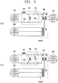
FIG. 5 illustrates two examples of a switch provided in a resonant tank, among examples of a DC-DC converter including a switch according to an embodiment of the present disclosure. -
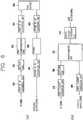
FIG. 6 is a block diagram illustrating an example DC-DC converter according to an embodiment of the present disclosure, as opposed to a typical example circuit including both a resonant converter and a PWM converter. - Description will now be given in detail according to exemplary embodiments disclosed herein, with reference to the accompanying drawings. For the sake of brief description with reference to the drawings, the same or equivalent components may be provided with the same or similar reference numbers, and description thereof will not be repeated. In general, a suffix such as "module" and "unit" may be used to refer to elements or components. Use of such a suffix herein is merely intended to facilitate description of the specification, and the suffix itself is not intended to give any special meaning or function. In describing the present disclosure, detailed description of related known functions or constructions may be omitted for the sake of brevity, but such description would be understood by those skilled in the art. The accompanying drawings are used to help easily understand the technical idea of the present disclosure and it should be understood that the idea of the present disclosure is not limited by the accompanying drawings. The idea of the present disclosure should be construed to extend to any alterations, equivalents and substitutes besides the accompanying drawings.
-
FIG. 2 are a block diagram (a) and a circuit diagram (b) illustrating an example structure of a DC-DC converter according to an embodiment of the present disclosure. - Referring to the block diagram (a) of
FIG. 2 , the DC-DC converter according to an embodiment of the present disclosure may include a firstcurrent conversion unit 210, aresonance tank 220, atransformation unit 230, a secondcurrent conversion unit 240, amain battery 250, and a thirdcurrent conversion unit 260. - The first
current conversion unit 210 can be configured to receive a DC current and convert the input DC current into an AC current for transformation. In some implementations, the DC current may be a DC current input to charge the main battery. For example, the DC current input to the firstcurrent conversion unit 210 may be a DC current to which an AC current supplied from a commercial power source has been converted by a power factor correction (PFC). In some implementations, the DC current input to the firstcurrent conversion unit 210 may be a current according to a voltage of the commercial power source, and may be a current having a voltage of about 400 V. - After the DC current is converted into an AC current having a frequency in the first
current conversion unit 210, the converted AC current may be input to aresonant tank 220. Theresonant tank 220 may include a resonant circuit having a resonant inductor and a capacitor, and may convert the frequency of the AC current input from the firstcurrent conversion unit 210 according to a resonant frequency of the resonant circuit. Then, the AC current with the converted frequency may be supplied to thetransformation unit 230. - The
transformation unit 230 may be connected to theresonant tank 220, and may transform the AC current applied from theresonant tank 220 into an AC current having a different voltage. For example, thetransformation unit 230 may transform the AC current supplied from theresonant tank 220 to an AC current of a charging voltage for themain battery 250, for example, a voltage corresponding to 48 V. Then, the transformed AC current may be output to the secondcurrent conversion unit 240. - When the AC current transformed by the
transformation unit 230 is input to the secondcurrent conversion unit 240, the secondcurrent conversion unit 240 may convert the input AC current into a DC current. In embodiments where the input AC current is of a charging voltage for themain battery 250, thecurrent conversion unit 240 can generate a DC current of the charging voltage capable of charging themain battery 250. The generated DC current may be supplied to themain battery 250 to charge themain battery 250. - In some implementations, when the power charged in the
main battery 250 is discharged, the secondcurrent conversion unit 240 can operate to receive a DC current from themain battery 250. For example, the secondcurrent conversion unit 240 may receive a DC current of 48 V equal to the operating voltage of themain battery 250. As such, when the current is input from themain battery 250, the secondcurrent conversion unit 240 may convert the input DC current into an AC current of 48 V and output the converted current to thetransformation unit 230. - In some implementations, the
transformation unit 230 can operate to transform the input AC current into a current according to an operation voltage of an auxiliary battery to supply or charge power for the additional devices or various additional devices provided in the electric vehicle. For example, when the operating voltage of the additional device and the auxiliary battery is 12 V, thetransformation unit 230 can operate to transform the AC current of 48 V into an AC current of 12 V and output the transformed AC current to the thirdcurrent conversion unit 260. - In some implementations, the third
current conversion unit 260 may be connected to the auxiliary battery to supply or charge power for the additional devices or various additional devices provided in the electric vehicle. When an AC current having the operating voltage of the additional devices and the auxiliary battery is applied, the thirdcurrent conversion unit 260 can operate to convert the AC current into a DC current. The converted DC current may be supplied to the connected additional device or the auxiliary battery. In the illustrated example, anauxiliary battery 270 is illustrated to be connected to the thirdcurrent conversion unit 260. - As described herein, the
transformation unit 230 of the DC-DC converter according to an embodiment of the present disclosure may be connected to both theresonant tank 220 and the thirdcurrent conversion unit 260, and also to the secondcurrent conversion unit 240. When a current is input from any one side, thetransformation unit 230 may convert the input current into a current having a different voltage according to electromagnetic induction and output the converted current. That is, when a current is applied from theresonant tank 220, thetransformation unit 230 of the DC-DC converter according to the embodiment may be configured to transform the input current and output the transformed current to the secondcurrent conversion unit 240. On the other hand, when a current is applied from the secondcurrent conversion unit 240, thetransformation unit 230 may be configured to output the applied current to the thirdcurrent conversion unit 260. - Therefore, when commercial power converted into a DC current by the PFC converter is applied, the first
current conversion unit 210, theresonant tank 220, thetransformation unit 230, the secondcurrent conversion unit 240 may be connected (280) in the DC-DC converter so as to vary a frequency of the current of the commercial power, to transform a voltage of the current having the varied frequency, and to supply the current with the transformed voltage to themain battery 250 as charging power. That is, when commercial power is applied, the DC-DC converter may operate as a resonant converter. - On the other hand, when power is applied from the
main battery 250, the secondcurrent conversion unit 240, thetransformation unit 230, and the thirdcurrent conversion unit 260 may be connected (290) in the DC-DC converter so as to transform the current supplied from themain battery 250 and to supply the transformed current to theauxiliary battery 270. That is, when power is applied from themain battery 250, the DC-DC converter may operate as a PWM converter. - Diagram (b) in
FIG. 2 illustrates an example circuit structure of theresonant tank 220 and thetransformation unit 230 in the DC-DC converter according to an embodiment of the present disclosure. - Referring to Diagram (b) of
FIG. 2 , thetransformation unit 230 may be provided with afirst inductor 232 connected to theresonant tank 220 and a third inductor connected to the thirdcurrent conversion unit 260 on one side of theinsulator 231, and asecond inductor 233 connected to the secondcurrent conversion unit 240 on an other side of theinsulator 231. For example, the third inductor may be configured by connecting a plurality of inductors 234, 235 in series. - In some implementations, the
resonant tank 220 may include aresonant inductor 221 and acapacitor 222. In addition, thefirst inductor 232 of thetransformation unit 230 may include anauxiliary inductor 225 such that ends of theauxiliary inductor 225 are connected to ends of thefirst inductor 232, respectively. That is, thefirst inductor 232 and theauxiliary inductor 225 may be connected in parallel to each other, and accordingly the inductance value required by the resonant converter may be generated in accordance with the parallel connection of thefirst inductor 232 and theauxiliary inductor 225 as shown inEquation 1 below.
- Here, L1 denotes an inductance of the first inductor, Le denotes an inductance of the auxiliary inductor, and L1 ∥ Le denotes an inductance when the L1 and Le are connected in parallel.
- In some implementations, according to the inductance L1 of the
first inductor 232, an inductance of thesecond inductor 233 may be determined according to a turns ratio between a side (first inductor 232) applying a current and a side (second inductor 233) receiving the current. This is expressed by Equation 2.
- Here, L1 denotes an inductance of the first inductor, L2 denotes an inductance of the second inductor, Np denotes a number of turns of an inductor at a side applying a current, and Ns denotes a number of turns of an inductor at a side receiving the current.
- Accordingly, when an inductance of the first inductor 232 (first inductance) is determined, an inductance of the second inductor 233 (second inductance) may be determined. In some implementations of the present disclosure, when power from the
main battery 250 is discharged, a side supplying a current and a side receiving a current may be changed at thetransformation unit 230. For example, the side supplying the current may be thesecond inductor 233 and the side receiving the current may be the third inductor 234, 235. In addition, as shown in Equation 2, because an inductance of a side receiving a current is determined according to an inductance of a side supplying a current, when a second inductance of thesecond inductor 233 is determined, a third inductance of the third inductor 234, 235 may also be determined in a manner similar to Equation 2. For example, because the second inductance may be greater as the first inductance is greater, the third inductance may be greater as the first inductance is greater. - In some implementations, unlike the operation as a resonant converter, the
transformation unit 230 can operate as a PWM converter transforming the supplied current by thesecond inductor 233 and the third inductor 234, 235, when themain battery 250 is discharged. Therefore, the greater the size of the third inductance is, the more thetransformation unit 230 operates efficiently. On the other hand, for the resonant converter that transforms a current input from a commercial power by thefirst inductor 232 and thesecond inductor 233, the size of thefirst inductor 232 may be limited because a specific inductance value is required. - However, as shown in Diagram (b) of
FIG. 2 , in embodiments that theauxiliary inductor 225 is connected in parallel with thefirst inductor 232, when the inductance of thefirst inductor 232 has a value sufficiently greater than that of the inductance of the auxiliary inductor 225 (that is, thefirst inductor 232 has a value with a preset level greater than that of the auxiliary inductor 225), inductance values of the parallel connected inductors (e.g., an inductance value of the auxiliary inductor 225) may be converged to a smaller value. - Therefore, regardless of the size of the
first inductor 232, the inductance value of theauxiliary inductor 225 may be the inductance value of thefirst inductor 232 and theauxiliary inductor 225 connected in parallel. Therefore, when an inductance of theauxiliary inductor 225 is determined according to an inductance value required in the resonant converter, it is possible to sufficiently increase the size of thefirst inductor 232. -
FIG. 3 show diagrams (a) and (b) to illustrate respective current flows when charging and discharging themain battery 250 in the DC-DC converter according to an embodiment of the present disclosure having theresonance tank 220 and thetransformation unit 230. - First, Diagram (a) of
FIG. 3 illustrates an example process in which a PFC converts an AC current of commercial power source into a DC current and inputs the same to the DC-DC converter according to an embodiment of the present disclosure. For example, the input current may beinput 300 to thetransformation unit 230 through the firstcurrent conversion unit 210 and theresonant tank 220, and the current transformed by thetransformation unit 230 may be supplied 310 to themain battery 250 through the secondcurrent conversion unit 240. - In some implementations, the
transformation unit 230 according to an embodiment of the present disclosure may also be connected to the thirdcurrent conversion unit 260 as illustrated inFIG. 2 . Accordingly, a reflection current 320 may be supplied to the thirdcurrent conversion unit 260 due to a voltage reflection phenomenon. For example, the reflection current 320 may be converted back into a DC current by the thirdcurrent conversion unit 260, and the converted reflection current 320 may be supplied as a charging current for theauxiliary battery 270. This is because the reflection current is reflected in a small amount according to a characteristic of thetransformation unit 230 and the voltage thereof is not high. Therefore, the reflection current may be used as a charging current for theauxiliary battery 270. In addition, since a path through which the reflection current flows in is also a path through which the current is output, there is no problem even when the reflection current is output, and rather be usable. - On the other hand, Diagram (b) of
Figure 3 illustrates an example process in which a current charged in the main battery is input to the DC-DC converter according to an embodiment of the present disclosure. For example, the input current may beinput 350 to thetransformation unit 230 through the secondcurrent conversion unit 240, and the current transformed by thetransformation unit 230 may be supplied 360 to theauxiliary battery 270 through the thirdcurrent conversion unit 260. - The
transformation unit 230 according to an embodiment of the present disclosure may also be connected to theresonant tank 220 as described above. Accordingly, the reflection current 320 may also be supplied to theresonant tank 220 due to the voltage reflection phenomenon. For example, a current may be input in a direction opposite to a direction in which power is output from theresonant tank 220, and the input current may be output through the firstcurrent conversion unit 210. - The first
current conversion unit 210 and theresonant tank 220 may form a path to supply a charging current to themain battery 250. In some instances, the current may be output in the reverse direction in which the current is supplied, and this output current may become a leakage current or cause burnout of elements or voltage stress or current stress due to the current. To control the current that is supplied in a reverse direction when power is supplied from themain battery 250, some implementations of the present disclosure may include at least one switch. -
FIGS. 4 and5 illustrate examples provided with at least one switch in the DC-DC converter according to the embodiment of the present disclosure. -
FIG. 4 illustrates examples in which aswitch unit 400 is provided between the firstcurrent conversion unit 210 and thetransformation unit 230. For example, theswitch unit 400 may be provided between the firstcurrent conversion unit 210 and the resonant tank 220 (as illustrated in Diagram (a) ofFIG. 4 ), or between theresonant tank 220 and the transformation unit 230 (as illustrated in Diagram (b) ofFIG. 4 ). In addition, theswitch unit 400 may disconnect the circuit by opening the circuit while the power is supplied from themain battery 250 to prevent the reflection current supplied from thetransformation unit 230 from flowing in. - Alternatively or in addition, the
switch unit 400 may be controlled by the PFC. For example, when the PFC converts a commercial AD current into a DC current, the PFC may control theswitch unit 400 so that between the firstcurrent conversion unit 210 and the resonant tank 220 (Diagram (a) ofFIG. 4 ) or between theresonant tank 220 and the transformation unit 230 (Diagram (b) ofFIG. 4 ) are connected. - On the other hand, when the commercial AC current is not converted into a DC current, the PFC allow the
switch unit 400 to disconnect the connection, thereby between the firstcurrent conversion unit 210 and the resonance tank 220 (Diagram (a) ofFIG. 4 ), or between theresonant tank 220 and the transformation unit 230 (Diagram (b) ofFIG. 4 ) may be disconnected. For example, only while the power to charge themain battery 250 is being supplied, the firstcurrent conversion unit 210, theresonant tank 220, and thetransformation unit 230 may be connected to each other. - In some implementations, at least one switch may be provided in the
resonant tank 220.FIG. 5 illustrates examples in which switches are provided in the resonant tank. - Diagram (a) of
FIG. 5 illustrates an example process -in which aswitch 510 is provided between one end of theauxiliary inductor 225 and one end of thefirst inductor 232 so as to connect or disconnect the twoinductors switch 510 is closed when a DC current to charge themain battery 250 is input to the firstcurrent conversion unit 210 so that the one end of theauxiliary inductor 225 and one end of thefirst inductor 232 may be connected to each other. - For example, when the
switch 510 is closed, theauxiliary inductor 225 and thefirst inductor 232 may be connected in parallel, and accordingly power conversion may be performed according to an inductance value upon the parallel connection of theauxiliary inductor 225 and thefirst inductor 232. That is, the firstcurrent conversion unit 210, theresonant tank 220, thetransformation unit 230, and the secondcurrent conversion unit 240 may be connected to operate as a resonant converter. - On the other hand, when a DC current is not supplied to the first
current conversion unit 210, theswitch 510 is kept in an open state so that the connection between the one end of theauxiliary inductor 225 and the one end of thefirst inductor 232 may be disconnected. For example, since the connection between theauxiliary inductor 225 and thefirst inductor 232 is disconnected, the connection between thetransformation unit 230 and theresonant tank 220 may also be disconnected. - Therefore, when a current is input from the
main battery 250 through the secondcurrent conversion unit 240, since the circuit of thefirst inductor 232 is cut off, the current may be transformed through the third inductor 234, 235 and thesecond inductor 233. The transformed current may be output to the thirdcurrent conversion unit 260. Therefore, the secondcurrent conversion unit 240, thetransformation unit 230, and the thirdcurrent conversion unit 260 are connected, so that the DC-DC converter according to the embodiment of the present disclosure may operate as a PWM converter. - In alternative implementations, as illustrated in Diagram (b) of
FIG. 5 , a plurality ofswitches 510 may be provided at ends of the first inductor and at ends of the auxiliary inductor, respectively. For example, theswitches - In addition, the
switch 510 or theswitches switch unit 400. That is, the PFC may control theswitch 510 or theswitches main battery 250 is being supplied, theswitch 510 or theswitches first conversion unit 210, theresonant tank 500, thetransformation unit 230, and thesecond conversion unit 240. - On the other hand, the PFC may control the
switch 510 or theswitches first inductor 232 of thetransformation unit 230 is disconnected (e.g., broken), the current may be transformed through the third inductor 234, 235 and thesecond inductor 233, and the transformed current may be output to the thirdcurrent conversion unit 260. That is, the secondcurrent conversion unit 240, thetransformation unit 230, and the thirdcurrent conversion unit 260 may be connected to operate as a PWM converter. As such, when operating as the PWM converter, current may be sequentially applied to thesecond conversion unit 240, thetransformation unit 230, and thethird conversion unit 260. -
FIG. 6 is a block diagram illustrating an example process in which the DC-DC converter according to an embodiment of the present disclosure is provided, as opposed to a typical example circuit including both a resonant converter and a PWM converter are provided. - Diagram (a) of
FIG. 6 illustrates an example process in which themain battery 250 includes both a resonant converter and a PWM converter. - Referring to Diagram (a) of
FIG. 6 , the resonant converter includes a first DC-AC conversion unit 600, aresonant tank 601, afirst transformation unit 602, and a first AC-DC conversion unit 604 and is connected to themain battery 250. Further, the PWM converter includes a second DC-AC conversion unit 605, asecond transformation unit 606, and a second AC-DC conversion unit 607 and is connected to themain battery 250. - In this case, when a commercial AC current is converted into a DC current in the PFC, the converted DC current 200 may be converted into an AC current by the first DC-
AC conversion unit 600. In addition, the current converted in the first DC-AC conversion unit 600 may vary in frequency by theresonant tank 601, and the AC current with the varied frequency may be transformed into a voltage to charge themain battery 250 by thefirst transformation unit 230. The transformed AC current may be input to the first AC-DC conversion unit 604, converted into DC current, and the converted DC current may be supplied to themain battery 250 to charge themain battery 250. - Meanwhile, the current of the
main battery 250 may be converted into an AC current by the second DC-AC conversion unit 605. The converted AC current may be transformed into an operating voltage for theauxiliary battery 270 and additional devices of the vehicle. And, the transformed AC current may be converted into a DC current by the second AC-DC conversion unit 607, and supplied as a power source for theauxiliary battery 270 and additional devices of the vehicle. - However, as illustrated in Diagram (a) of
FIG. 6 , a plurality of DC-AC conversion units and AC-DC conversion units are provided and a plurality of transformation units are also provided, when both the resonant converter and the PWM converter are provided. Accordingly, an internal space to install the DC-DC converter is required. - On the contrary, Diagram (b) of
FIG. 6 illustrates an example process in which themain battery 250 is provided with a DC-DC converter operable as both a resonant converter and a PWM converter, according to an embodiment of the present disclosure. - Referring to Diagram (b) of
Figure 6 , the DC-DC converter according to the embodiment of the present disclosure may be provided only with the firstcurrent conversion unit 210, theresonant tank 220, thetransformation unit 230, the secondcurrent conversion unit 240 and the thirdcurrent conversion unit 260. Accordingly, in the DC-DC converter according to the embodiment of the present disclosure, the transformation units and the current conversion units can be further reduced in number, and an inner space of the electric vehicle required to install the DC-DC converter may be reduced. As a result, the inner space of the electric vehicle can be used more efficiently. - Meanwhile, several embodiments have been described herein, but various modifications may be made without departing from the scope of the present disclosure. Therefore, those skilled in the art to which the present disclosure pertains would understand various modifications and variations will be possible without departing from the essential characteristics of the present disclosure. Therefore, the embodiments disclosed herein are not intended to limit the technical idea of the present disclosure, and the scope of the technical idea of the present disclosure is not limited by these embodiments. The scope of some implementations of the present disclosure is interpreted by the following claims, and all technical ideas within the equivalent scope should be interpreted as being included in the scope of the present disclosure.
Claims (14)
- A direct-current to direct-current (DC-DC) converter comprising:a first converter(210);a resonant tank(220) coupled to the first converter(210);a second converter(240);a third converter(260); anda transformer(230) having a first side coupled to the resonant tank(220) and the third converter(260), and a second side coupled to the second converter(240),wherein, based on a first direct current (DC)(200) being input to the DC-DC converter:the first converter(210) is configured to receive the first DC(200) and convert the received first DC(200) into a first alternating current (AC);the resonant tank(220) is configured to receive the first AC from the first converter(210) and adjust a frequency of the first AC;the transformer(230) is configured to receive and transform the first AC with the adjusted frequency into a second AC having a charging voltage for a main battery(250) of an electric vehicle, and output the second AC to the second converter(240); andthe second converter(240) is configured to convert the second AC having the charging voltage for the main battery(250) into a second DC for charging the main battery(250); andwherein, based on a third DC being input from the main battery(250):the second converter(240) is configured to receive the third DC from the main battery(250) and convert the third DC into a third AC;the transformer(230) is configured to receive and transform the third AC into a fourth AC having a specific voltage, and output the fourth AC to the third converter(260); andthe third converter(260) is configured to receive the fourth AC and convert the fourth AC into a fourth DC to be supplied to one or more devices located in the electric vehicle.
- The converter of claim 1, wherein the transformer(230) comprises:an insulator(231) having a first insulator side and a second insulator side;a first inductor(232) and a third inductor(234, 235) provided at the first insulator side of the insulator(231), the first inductor(232) connected to the first converter(210), and the third inductor(234, 235) connected to the third converter(260); anda second inductor(233) provided at the second insulator side of the insulator(231) and connected to the second converter(240);wherein the transformer(230), based on the first AC being input through the first inductor(232), is configured transform the first AC into the second AC having the charging voltage for the main battery(250) according to a turn ratio between the first inductor(232) and the second inductor(233), andwherein the transformer(230), based on the third AC being input through the second inductor(233), is configured to transform the third AC into the fourth AC having the specific voltage according to a turn ratio between the second inductor(233) and the third inductor(234, 235).
- The converter of claim 2, wherein an inductance of the second inductor(233) is determined according to an inductance of the first inductor(232), and
an inductance of the third inductor(234, 235) is determined according to the inductance of the second inductor(233). - The converter of claim 3, wherein the third inductor(234, 235) includes a plurality of inductors connected in series.
- The converter of anyone of claims 2 to 4, wherein the resonant tank(220) comprises:an auxiliary inductor(225) having ends connected to ends of the first inductor(232) of the transformer(230), respectively; andat least one switch, each provided between one of the ends of the first inductor(232) and one of the ends of the auxiliary inductor to selectively connect the one of the ends of the auxiliary inductor and the one of the ends of the first inductor(232),wherein, based on the first DC(200) being input to the DC-DC converter, the at least one switch is each configured to be closed to connect the ends of the auxiliary inductor and the ends of the first inductor(232), respectively, and, based on absence of the first DC(200) from input to the DC-DC converter, the at least one switch is each configured to be opened to release the connection between the ends of the auxiliary inductor and the ends of the first inductor(232).
- The converter of claim 5, wherein the auxiliary inductor of the resonant tank(220) is configured to be connected with the first inductor(232) in parallel based on the at least one switch being closed, to generate an inductance that allows the transformer(230) to transform the first AC into the second AC having the charging voltage for the main battery(250).
- The converter of claim 6, wherein an inductance of the first inductor(232) is predetermined to be greater than an inductance of the auxiliary inductor(225).
- The converter of anyone of claims 1 to 7, further comprising:a switch provided between the first converter(210) and the resonant tank(220) or between the resonant tank(220) and the transformer(230),wherein the switch is configured to be closed based on the first DC(200) being input to the DC-DC converter, or open based on absence of the first DC(200) from input to the DC-DC converter.
- The converter of claim 5, further comprising:
a power factor correction (PFC) converter configured to convert a commercial AC into the first DC(200), the power factor correct converter configured to control the at least one switch to be closed based on the commercial AC being converted into the first DC(200). - The converter of claim 8, further comprising:
a power factor correction (PFC) converter configured to convert a commercial AC into the first DC(200), the power factor correct converter configured to control the switch to be closed based on the commercial AC being converted into the first DC(200). - The converter of claim 5, wherein the DC-DC converter operates as a resonant converter in which the at least one switch is closed and a current is sequentially applied through the first converter(210), the resonant tank(220), the transformer(230), and the second converter(240), and operates as a pulse width modulation (PWM) converter in which the at least one switch is open and a current is sequentially applied through the second converter(240), the transformer(230), and the third converter(260).
- The converter of claim 8, wherein the DC-DC converter operates as a resonant converter in which the switch is closed and a current is sequentially applied through the first converter(210), the resonant tank(220), the transformer(230), and the second converter(240), and operates as a pulse width modulation (PWM) converter in which the switch is open and a current is sequentially applied through the second converter(240), the transformer(230), and the third converter(260).
- The converter of anyone of claims 1 to 12, wherein the resonant tank(220) includes a resonant inductor(221) and a capacitor(222).
- A method of reversibly operating a direct current to direct current (DC-DC) converter, comprising:based on a first direct current (DC) being input to the DC-DC converter in a first direction,converting, using a first converter(210), the first direct current (DC) to a first alternating current (AC);adjusting, using a resonant tank(220), a frequency of the first AC;transforming, using a transformer(230), the first AC with the adjusted frequency into a second AC; andconverting, using a second converter(240), the second AC into a second DC, andbased on a third DC being input to the DC-DC converter in a second direction reverse to the first direction,converting, using the second converter(240), the third DC into a third AC;transforming, using the transformer(230), the third AC to a fourth AC; andconverting, using a third converter(260), the fourth AC to a fourth DC.
Applications Claiming Priority (1)
| Application Number | Priority Date | Filing Date | Title |
|---|---|---|---|
| KR1020180174076A KR20200094810A (en) | 2018-12-31 | 2018-12-31 | Dc-dc converter for electric vehicle |
Publications (1)
| Publication Number | Publication Date |
|---|---|
| EP3675341A1 true EP3675341A1 (en) | 2020-07-01 |
Family
ID=69055735
Family Applications (1)
| Application Number | Title | Priority Date | Filing Date |
|---|---|---|---|
| EP19219801.8A Withdrawn EP3675341A1 (en) | 2018-12-31 | 2019-12-27 | Dc-dc converter for electric vehicle |
Country Status (4)
| Country | Link |
|---|---|
| US (1) | US20200207234A1 (en) |
| EP (1) | EP3675341A1 (en) |
| KR (1) | KR20200094810A (en) |
| CN (1) | CN111431410A (en) |
Families Citing this family (2)
| Publication number | Priority date | Publication date | Assignee | Title |
|---|---|---|---|---|
| ES2983802T3 (en) * | 2021-07-29 | 2024-10-24 | Contemporary Amperex Technology Hong Kong Ltd | Charging/discharging apparatus, battery charging and discharging method and charging/discharging system |
| KR20240020975A (en) * | 2022-08-09 | 2024-02-16 | 현대자동차주식회사 | Converter and power conversion system which converts auxiliary battery power using using obc |
Citations (1)
| Publication number | Priority date | Publication date | Assignee | Title |
|---|---|---|---|---|
| US20180222333A1 (en) * | 2014-06-13 | 2018-08-09 | University Of Maryland | Integrated dual-output grid-to-vehicle (g2v) and vehicle-to-grid (v2g) onboard charger for plug-in electric vehicles |
Family Cites Families (1)
| Publication number | Priority date | Publication date | Assignee | Title |
|---|---|---|---|---|
| KR102020648B1 (en) * | 2017-05-26 | 2019-09-11 | 주식회사 솔루엠 | Transformer and LLC Resonant Converter having the same |
-
2018
- 2018-12-31 KR KR1020180174076A patent/KR20200094810A/en not_active Abandoned
-
2019
- 2019-12-27 EP EP19219801.8A patent/EP3675341A1/en not_active Withdrawn
- 2019-12-30 CN CN201911392379.4A patent/CN111431410A/en not_active Withdrawn
- 2019-12-31 US US16/731,968 patent/US20200207234A1/en not_active Abandoned
Patent Citations (1)
| Publication number | Priority date | Publication date | Assignee | Title |
|---|---|---|---|---|
| US20180222333A1 (en) * | 2014-06-13 | 2018-08-09 | University Of Maryland | Integrated dual-output grid-to-vehicle (g2v) and vehicle-to-grid (v2g) onboard charger for plug-in electric vehicles |
Non-Patent Citations (2)
| Title |
|---|
| KRISHNASWAMI H ET AL: "Three-Port Series-Resonant DC-DC Converter to Interface Renewable Energy Sources With Bidirectional Load and Energy Storage Ports", IEEE TRANSACTIONS ON POWER ELECTRONICS, INSTITUTE OF ELECTRICAL AND ELECTRONICS ENGINEERS, USA, vol. 12, no. 10, 1 October 2009 (2009-10-01), pages 2289 - 2297, XP011271821, ISSN: 0885-8993 * |
| ZHANG NENG ET AL: "A review of topologies of three-port DC-DC converters for the integration of renewable energy and energy storage system", RENEWABLE AND SUSTAINABLE ENERGY REVIEWS, vol. 56, 1 April 2016 (2016-04-01), pages 388 - 401, XP029387107, ISSN: 1364-0321, DOI: 10.1016/J.RSER.2015.11.079 * |
Also Published As
| Publication number | Publication date |
|---|---|
| US20200207234A1 (en) | 2020-07-02 |
| KR20200094810A (en) | 2020-08-10 |
| CN111431410A (en) | 2020-07-17 |
Similar Documents
| Publication | Publication Date | Title |
|---|---|---|
| JP6942852B2 (en) | Insulated DC / DC converter for wide output voltage range and its control method | |
| CN108463935B (en) | Bidirectional DC/DC converter and method for charging an intermediate circuit capacitor of a DC/DC converter from a low voltage battery | |
| Xiao et al. | A ZVS bidirectional DC–DC converter with phase-shift plus PWM control scheme | |
| US8811039B2 (en) | Pulse width modulated resonant power conversion | |
| US9866146B2 (en) | Enhanced flyback converter | |
| US20160181925A1 (en) | Bidirectional dc-dc converter | |
| CN109728624A (en) | Vehicle-mounted charge-discharge system | |
| US20090290389A1 (en) | Series resonant converter | |
| JP2016019463A (en) | Pulse width modulation resonant converter, and vehicle charger utilizing the same | |
| MX2011009361A (en) | Battery charger using phase shift double forward converting circuit. | |
| US5717579A (en) | Power supply unit, more specifically battery charger for electric vehicles and the like | |
| Kondo et al. | Proposition and experimental verification of a bi-directional isolated DC/DC converter for battery charger-discharger of electric vehicle | |
| EP3675341A1 (en) | Dc-dc converter for electric vehicle | |
| KR20210003539A (en) | Dc-dc converter | |
| KR102131948B1 (en) | Variable capacity power bank system | |
| TWI862411B (en) | Bidirectional voltage conversion device | |
| KR101937013B1 (en) | Power factor correction converter | |
| Lee et al. | Bidirectional Performance-considered 11 kW Integrated Wired/Wireless EV Charging System with Effective Operation Strategy | |
| CN115411921A (en) | Converter and inverter | |
| Kumar et al. | Analysis of Isolated DC-DC Coupled-Inductor Based Dual Active Bridge Converter for EV Charging Systems | |
| Noh et al. | Control method to increase efficiency of 3-phase current-fed dual active bridge converter | |
| US20250096693A1 (en) | Dc-dc converter for battery charging circuit | |
| KR20250042033A (en) | Converting circuit for on-board charging device | |
| EP4668565A1 (en) | Power conversion device | |
| Das et al. | A novel three-level DC-DC converter with load adaptive ZVS auxiliary circuit |
Legal Events
| Date | Code | Title | Description |
|---|---|---|---|
| PUAI | Public reference made under article 153(3) epc to a published international application that has entered the european phase |
Free format text: ORIGINAL CODE: 0009012 |
|
| STAA | Information on the status of an ep patent application or granted ep patent |
Free format text: STATUS: REQUEST FOR EXAMINATION WAS MADE |
|
| 17P | Request for examination filed |
Effective date: 20200127 |
|
| AK | Designated contracting states |
Kind code of ref document: A1 Designated state(s): AL AT BE BG CH CY CZ DE DK EE ES FI FR GB GR HR HU IE IS IT LI LT LU LV MC MK MT NL NO PL PT RO RS SE SI SK SM TR |
|
| AX | Request for extension of the european patent |
Extension state: BA ME |
|
| RBV | Designated contracting states (corrected) |
Designated state(s): AL AT BE BG CH CY CZ DE DK EE ES FI FR GB GR HR HU IE IS IT LI LT LU LV MC MK MT NL NO PL PT RO RS SE SI SK SM TR |
|
| GRAP | Despatch of communication of intention to grant a patent |
Free format text: ORIGINAL CODE: EPIDOSNIGR1 |
|
| STAA | Information on the status of an ep patent application or granted ep patent |
Free format text: STATUS: GRANT OF PATENT IS INTENDED |
|
| INTG | Intention to grant announced |
Effective date: 20210924 |
|
| STAA | Information on the status of an ep patent application or granted ep patent |
Free format text: STATUS: THE APPLICATION IS DEEMED TO BE WITHDRAWN |
|
| 18D | Application deemed to be withdrawn |
Effective date: 20220205 |