EP3675334A1 - Electric power steering device - Google Patents
Electric power steering device Download PDFInfo
- Publication number
- EP3675334A1 EP3675334A1 EP17922803.6A EP17922803A EP3675334A1 EP 3675334 A1 EP3675334 A1 EP 3675334A1 EP 17922803 A EP17922803 A EP 17922803A EP 3675334 A1 EP3675334 A1 EP 3675334A1
- Authority
- EP
- European Patent Office
- Prior art keywords
- end portion
- housing
- connector
- outer peripheral
- peripheral end
- Prior art date
- Legal status (The legal status is an assumption and is not a legal conclusion. Google has not performed a legal analysis and makes no representation as to the accuracy of the status listed.)
- Granted
Links
Images


Classifications
-
- H—ELECTRICITY
- H02—GENERATION; CONVERSION OR DISTRIBUTION OF ELECTRIC POWER
- H02K—DYNAMO-ELECTRIC MACHINES
- H02K11/00—Structural association of dynamo-electric machines with electric components or with devices for shielding, monitoring or protection
- H02K11/30—Structural association with control circuits or drive circuits
- H02K11/33—Drive circuits, e.g. power electronics
-
- H—ELECTRICITY
- H02—GENERATION; CONVERSION OR DISTRIBUTION OF ELECTRIC POWER
- H02K—DYNAMO-ELECTRIC MACHINES
- H02K5/00—Casings; Enclosures; Supports
- H02K5/04—Casings or enclosures characterised by the shape, form or construction thereof
- H02K5/10—Casings or enclosures characterised by the shape, form or construction thereof with arrangements for protection from ingress, e.g. water or fingers
-
- B—PERFORMING OPERATIONS; TRANSPORTING
- B62—LAND VEHICLES FOR TRAVELLING OTHERWISE THAN ON RAILS
- B62D—MOTOR VEHICLES; TRAILERS
- B62D5/00—Power-assisted or power-driven steering
- B62D5/04—Power-assisted or power-driven steering electrical, e.g. using an electric servo-motor connected to, or forming part of, the steering gear
- B62D5/0403—Power-assisted or power-driven steering electrical, e.g. using an electric servo-motor connected to, or forming part of, the steering gear characterised by constructional features, e.g. common housing for motor and gear box
-
- B—PERFORMING OPERATIONS; TRANSPORTING
- B62—LAND VEHICLES FOR TRAVELLING OTHERWISE THAN ON RAILS
- B62D—MOTOR VEHICLES; TRAILERS
- B62D5/00—Power-assisted or power-driven steering
- B62D5/04—Power-assisted or power-driven steering electrical, e.g. using an electric servo-motor connected to, or forming part of, the steering gear
- B62D5/0457—Power-assisted or power-driven steering electrical, e.g. using an electric servo-motor connected to, or forming part of, the steering gear characterised by control features of the drive means as such
- B62D5/046—Controlling the motor
-
- H—ELECTRICITY
- H01—ELECTRIC ELEMENTS
- H01R—ELECTRICALLY-CONDUCTIVE CONNECTIONS; STRUCTURAL ASSOCIATIONS OF A PLURALITY OF MUTUALLY-INSULATED ELECTRICAL CONNECTING ELEMENTS; COUPLING DEVICES; CURRENT COLLECTORS
- H01R13/00—Details of coupling devices of the kinds covered by groups H01R12/70 or H01R24/00 - H01R33/00
- H01R13/46—Bases; Cases
- H01R13/52—Dustproof, splashproof, drip-proof, waterproof, or flameproof cases
- H01R13/5202—Sealing means between parts of housing or between housing part and a wall, e.g. sealing rings
-
- H—ELECTRICITY
- H02—GENERATION; CONVERSION OR DISTRIBUTION OF ELECTRIC POWER
- H02K—DYNAMO-ELECTRIC MACHINES
- H02K5/00—Casings; Enclosures; Supports
- H02K5/04—Casings or enclosures characterised by the shape, form or construction thereof
- H02K5/22—Auxiliary parts of casings not covered by groups H02K5/06-H02K5/20, e.g. shaped to form connection boxes or terminal boxes
- H02K5/225—Terminal boxes or connection arrangements
Definitions
- the present invention relates to an electric power steering device in which a motor and a control device are integrated with each other.
- the electric power steering device in which a control device is disposed coaxially with an output shaft of a motor, and in which the motor and the control device are integrated with each other.
- the electric power steering device in which the motor and the control device are integrated with each other has the following structure.
- a connector is provided to a housing of the control device.
- a stator, a rotor, and other components are built in a case of the motor.
- the housing of the control device is coupled to the case of the motor (for example, see Patent Literature 1).
- the present invention has been made to solve the problem described above, and obtains an electric power steering device, which is capable of improving easy of manufacture thereof.
- an electric power steering device including a motor; and a control device, wherein the motor includes a case which is opened at one end portion
- the control device includes: a control device main body; a connector connected to the control device main body; and a housing having a cylindrical shape which is opened at one end portion and closed at another end portion, wherein the housing houses the control device main body, wherein the case and the housing are coupled to each other in a state in which an outer peripheral end portion at the one end portion of the case and an outer peripheral end portion at the one end portion of the housing face each other, wherein a first sealing material is disposed between the outer peripheral end portion of the case and the outer peripheral end portion of the housing, wherein the connector is disposed between the outer peripheral end portion of the case and the outer peripheral end portion of the housing, wherein a second sealing material is disposed between the housing and at least one surface facing the housing among a plurality of surfaces which form an outer periphery of the connector, and wherein a part of
- the sealed regions between three components which are the housing, the case, and the connector, can be coupled to one another.
- the sealing process can be simplified, and the man-hours for manufacture can be reduced.
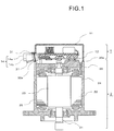
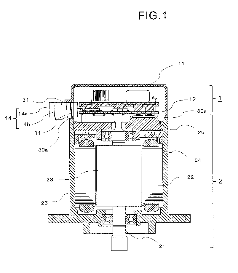
- FIG. 1 is a configuration view for illustrating an electric power steering device according to a first embodiment of the present invention.
- FIG. 2 is a perspective view for illustrating a housing 11 of FIG. 1 .
- the electric power steering device includes a control device 1 and a motor 2.
- the control device 1 and the motor 2 are coupled to each other through intermediation of a first sealing material 30a and a second sealing material 31.
- the motor 2 includes an output shaft 21, a stator 22, a rotor 23, a case 25, and a frame 26.
- the output shaft 21, the stator 22, and the rotor 23 are housed in the case 25.
- the case 25 has a cylindrical shape which is opened at one end portion, and a through hole is formed in another end portion of the output shaft 21. The opening in the one end portion of the case 25 is closed by the frame 26.
- One end portion of the output shaft 21 is rotatably supported by the case 25 through intermediation of a bearing, and another end portion of the output shaft 21 is rotatably supported by the frame 26 through intermediation of a bearing.
- the one end portion of the output shaft 21 protrudes outward from the through hole in another end portion of the case 25.
- the rotor 23 is fixed to the output shaft 21.
- the stator 22 is disposed in a state of surrounding an outer periphery of the rotor 23.
- a plurality of permanent magnets (not shown) are provided on an outer peripheral portion of the rotor 23.
- a winding 24 is wound around the stator 22.
- the frame 26 is fixed on an inner side of the case 25.
- a connection portion between the frame 26 and the case 25 is not exposed to an outer side of the case 25. Therefore, it is not required to seal the connection portion between the frame 26 and the case 25.
- the frame 26 is mounted on the inner side of the case 25, and hence regions required to be sealed are reduced.
- the control device 1 includes the housing 11, a control device main body 12, and a connector 14.
- the connector 14 includes connectors 14a and 14b of two different types which are integrated with each other.
- the connector 14 includes a plurality of terminals . Each of the plurality of terminals of the connector 14 is electrically connected to the control device main body 12.
- a harness for supplying power to the control device main body 12 and a harness for transmitting and receiving signals are connected to the connector 14 from the outside.
- the control device main body 12 is housed inside the housing 11.
- the connector 14 penetrates the housing 11, and a part thereof is exposed to an outside of the housing 11.
- the control device main body 12 includes a control board and a relay board.
- the control board includes a plurality of electronic components.
- the control device main body 12 is in contact with the frame 26.
- the frame 26 serves as a heat sink for the plurality of electronic components included in the control device main body 12.
- the housing 11 has a cylindrical shape which is opened at one end portion and closed at another end portion.
- An outer peripheral end portion 11a is formed at the one end portion of the housing 11.
- a connector mounting portion 11A is formed at a part of the outer peripheral end portion 11a.
- the connector mounting portion 11A includes a cutout portion 11B and a connector mounting base 11b.
- the cutout portion 11B is formed so as to extend from the outer peripheral end portion 11a toward another end portion of the housing 11.
- the connector mounting base 11b is formed at a bottom portion of the cutout portion 11B and protrudes toward a radially outer side of the housing.
- inclined portions 11c which are inclined so as to extend from the outer peripheral end portion 11a of the housing toward the connector mounting base 11b of the housing are formed.
- the inclined portions 11c may be perpendicular to the outer peripheral end portion 11a.
- a connector mounting base end portion 11d connected to the inclined portions 11c is formed so as to extend along a peripheral edge portion of the connector mounting base 11b.
- one surface among four surfaces which form an outer periphery of the connector 14 is disposed on the connector mounting base 11b.
- two surfaces facing each other are disposed at positions adjacent to the inclined portions 11c, respectively.
- a part of the connector 14 disposed on the connector mounting portion 11A protrudes to the outside of the housing 11 from the cutout portion 11B.
- a portion between the one surface which forms the outer periphery of the connector 14 and the connector mounting base end portion 11d and a portion between each of the inclined portions 11c and a corresponding one of the two surfaces which form the outer periphery of the connector 14 and face each other are sealed by the second sealing material 31.
- the remaining one surface which is other than the surface facing the connector mounting base 11b and the two surfaces adjacent to the two inclined portions 11c, faces an opening-side outer peripheral end portion of the case 25.
- This remaining one surface is sealed by the first sealing material 30a that seals a portion between the outer peripheral end portion 11a of the housing 11 and the opening-side outer peripheral end portion of the case 25.
- the connector 14 is disposed between the housing 11 of the control device 1 and the case 25 of the motor 2.
- the portion between the housing 11 and each of the three surfaces facing the housing 11 is sealed by the second sealing material 31.
- the portion between the remaining one surface and the outer peripheral end portion of the case 25 is sealed by the first sealing material 30a that seals the outer peripheral end portion 11a of the housing 11 and the outer peripheral end portion of the case 25.
- the first sealing material 30a and the second sealing material 31 adhere to each other.
- the sealed regions between the housing 11 of the control device 1, the case 25 of the motor 2, and the connector 14 can be reduced. Therefore, the sealing process can be simplified, and the man-hours for manufacture can be reduced. It is not always required that the first sealing material 30a and the second sealing material 31 be made of the same material, and any materials that have excellent affinity may be adopted.
- the cutout portion 11B is formed in the housing 11, which enables the connector 14 to be disposed on the connector mounting base 11b from the opening side of the housing 11.
- the connector 14 and the control device main body 12 can be disposed in the housing 11 without applying a load to the control device main body 12 to which the plurality of terminals of the connector 14 are connected. Moreover, the connector 14 and the control device main body 12 can be disposed in the housing 11 from one direction. Therefore, the manufacturing process can be simplified.
- the second sealing material 31 in a form of paste is applied to the connector mounting base end portion 11d and the two inclined portions 11c, which form the connector mounting portion 11A of the housing 11.
- control device main body 12 is disposed inside the housing 11, and the connector 14 is disposed on the connector mounting portion 11A of the housing 11.
- the second sealing material 31 is disposed at the portion between the housing 11 and each of the three surfaces among the four surfaces which form the outer periphery of the connector 14.
- the first sealing material 30a is applied to the opening-side outer peripheral end portion of the case 25.
- the first sealing material 30a is disposed at the portion between the remaining one surface of the connector 14 and the outer peripheral end portion of the case 25.
- the first sealing material 30a and the second sealing material 31 are cured.
- the portions between the housing 11 of the control device 1, the case 25 of the motor 2, and the outer periphery of the connector 14 are sealed.
- the first sealing material 30a is applied to the opening-side outer peripheral end portion of the case 25 of the motor 2, to thereby seal the portion between the housing 11 and the case 25.
- a method for sealing the portion between the housing 11 and the case 25 is not limited to this.
- the second sealing material 31 is applied to the outer peripheral end portion 11a of the housing 11, the connector mounting base 11b which forms the connector mounting portion 11A, and the two inclined portions 11c. Then, after the connector 14 is disposed on the connector mounting portion 11A, the second sealing material 31 is further applied to an upper surface of the connector 14. Then, the opening-side outer peripheral end portion of the case 25 and the outer peripheral end portion 11a of the housing 11 are brought into abutment against each other, to thereby seal the portions between the housing 11, the case 25 and the connector 14.
- the second sealing material 31 can be applied to the outer peripheral end portion 11a of the housing 11, the inclined portions 11c, and the connector mounting base end portion 11d continuously from the same direction.
- the sealing material to be applied may be the first sealing material 30a.
- FIG. 3A to FIG. 3C are schematic views for illustrating a sealing portion of a housing 11, a connector 14, and a case 25 of a motor 2 in an electric power steering device according to a second embodiment.
- the electric power steering device according to the second embodiment is different from the electric power steering device according to the first embodiment in that a space for housing a surplus sealing material is formed in a periphery of a region in which a region to which the first sealing material 30a is applied and a region to which the second sealing material 31 is applied intersect each other.
- Other configurations are similar to those of the first embodiment.
- FIG. 3A is an illustration of a state in which the housing 11 and the connector 14 are sealed by the second sealing material 31.
- the second sealing material 31 sticks out from the sealing portion of the housing 11 and the connector 14.
- a sealing material having an amount slightly larger than necessary is disposed and caused to stick out so that a gap is not formed between the two components.
- a space 32a for housing this surplus second sealing material 31 that sticks out is formed in both of the housing 11 and the connector 14.
- FIG. 3B is an illustration of a state in which, after the housing 11 and the connector 14 are sealed, the first sealing material 30a is disposed on the case 25 of the motor 2, and the portion between the housing 11, the connector 14, and the case 25 is sealed. As illustrated in FIG. 3B , the first sealing material 30a disposed on the case 25 of the motor 2 is also disposed in a space 32a formed in the housing 11 and the connector 14. Then, the first sealing material 30a and the second sealing material 31 adhere to each other in the space 32a.
- the space 32a is formed in the housing 11 and the connector 14 in the region in which the second sealing material 31 disposed between the housing 11 and the connector 14 and the first sealing material 30a disposed on the case 25 intersect each other.
- the surplus first sealing material 30a and the surplus second sealing material 31 are housed in the space 32a.
- the first sealing material 30a and the second sealing material 31 adhere to each other in the space 32a, and a gap is prevented from being formed in the sealing portion.
- the first sealing material 30a and the second sealing material 31 are prevented from sticking out from the housing 11, the connector 14, and the case 25.
- a joint of the sealing portion can be reliably sealed, and in addition, a step of removing the first sealing material 30a and the second sealing material 31, which sticks out, is reduced.
- the sealing process can be simplified.
- the space 32a is formed in both of the housing 11 and the connector 14 in FIG. 3A and FIG. 3B .
- the space 32a may be formed in only one of the housing 11 and the connector 14.
- the case 25 of the motor 2 is brought into abutment against the housing 11 from above in FIG. 3A and FIG. 3B .
- the case 25 of the motor 2 may be located below, and the housing 11 may be brought into abutment against the case 25 of the motor 2 from above as illustrated in FIG. 3C .
- the space 32b is formed in the case 25 of the motor 2. As described above, when the space 32a or the space 32b is formed in the component located below in the sealing process, the surplus sealing material is likely to be received.
- FIG. 4A and FIG. 4B are views for illustrating an electric power steering device according to a third embodiment.
- the electric power steering device according to the third embodiment is different from the electric power steering device according to the second embodiment in that a height of an upper surface of the housing 11 and a height of an upper surface of the connector 14 are different from each other.
- Other configurations are similar to those of the first embodiment.
- the height of the upper surface of the housing 11 is a lowest height H1, which is lower than a height of an upper surface H2 of the connector 14.
- the upper surface of the housing 11 is higher as separating away from the sealing portion of the housing 11 and the connector 14, and the height thereof at a position most distant from the region in which the housing 11 and the connector 14 are sealed is H3 higher than the upper surface H2 of the connector 14.
- a space 32c is formed in the upper surface of the housing 11 in the region in which the housing 11 and the connector 14 are sealed. With the presence of this space 32c, the second sealing material 31 that sticks out from an end portion between the housing 11 and the connector 14 is housed in the space 32c.
- the housing 11 and the connector 14 are sealed by the second sealing material 31 as illustrated in FIG. 4A .
- the first sealing material 30a is applied to upper portions of the housing 11 and the connector 14, and a case 25 of a motor 2 is brought into abutment against each other from above.
- an amount of the first sealing material 30a is adjusted so as to be larger in the vicinity of the space 32c.
- This adjustment can be performed by controlling a discharge rate of the first sealing material 30a discharged from a sealing device or by controlling a moving speed of the sealing device.
- the adjustment of an application amount of the first sealing material 30a is performed more easily by controlling the moving speed of the sealing device. That is, the sealing device is moved at low speed on an upper portion of the space 32c to increase the application amount of the first sealing material 30a, and the sealing device is moved at middle speed on the upper portion of the connector 14. The sealing device is moved while being accelerated on the upper portion of the housing 11 so that the application amount of the first sealing material 30a can be reduced as the height of the housing 11 becomes higher.
- FIG. 4B is a modification example of the third embodiment.
- a groove for holding the first sealing material 30a is formed in an outer peripheral end portion 11a of the housing 11.
- a height H1 of a bottom portion of the groove is higher than a height H2 of the upper portion of the connector 14. Therefore, a space 32C is formed between the bottom portion of the groove of the housing 11 and the upper portion of the connector 14.
- the housing 11 and the connector 14 are sealed by the second sealing material 31 as illustrated in FIG. 4B .
- the first sealing material 30a is applied to upper portions of the housing 11 and the connector 14, and a case 25 of a motor 2 is brought into abutment against each other from above.
- an application amount of the first sealing material 30a is adjusted so as to be larger in the vicinity of the space 32c. That is, the sealing device is moved on the upper portions of the space 32c and the connector 14 at low speed to increase the application amount of the first sealing material 30a, and the sealing device is moved at high speed on the upper portion of the housing 11 to reduce the application amount of the first sealing material 30a. Further, in the modification example illustrated in FIG. 4B , the groove for holding the first sealing material 30a is also formed in the upper surface of the connector 14.
- the surplus first sealing material 30a and the surplus second sealing material 31 are caused to stick out to the space 32c. Further, the application amount of the first sealing material 30a is increased on the upper portion of the space 32c and the upper portion of the connector 14, and the application amount of the first sealing material 30a is reduced in the vicinity of the portion in which the height of the housing 11 is high.
- first sealing material 30a and the second sealing material 31 can be applied to the respective sealed regions.
- first sealing material 30a and the second sealing material 31 can adhere to each other in the space 32c.
- reliable sealing can be performed in the region in which the sealing portions intersect each other.
- first sealing material 30a and the second sealing material 31 can be prevented from sticking out to the outside of the housing 11, the connector 14, and the case 25.
- the step of removing the first sealing material 30a and the second sealing material 31, which stick out, is reduced, and the sealing process can be simplified.
- control device 1 control device, 2 motor, 11 housing, 11a outer peripheral end portion, 11b connector mounting base, 11c inclined portion, 11d connector mounting base end portion, 11A connector mounting portion, 11B cutout portion, 12 control device main body, 14 connector, 21 output shaft, 22 stator, 23 rotor, 24 winding, 25 case, 30a first sealing material, 31 second sealing material, 32a, 32b space (recessed portion), 32c space
Landscapes
- Engineering & Computer Science (AREA)
- Power Engineering (AREA)
- Chemical & Material Sciences (AREA)
- Combustion & Propulsion (AREA)
- Transportation (AREA)
- Mechanical Engineering (AREA)
- Microelectronics & Electronic Packaging (AREA)
- Power Steering Mechanism (AREA)
- Motor Or Generator Frames (AREA)
Abstract
Description
- The present invention relates to an electric power steering device in which a motor and a control device are integrated with each other.
- Hitherto, there has been known an electric power steering device, in which a control device is disposed coaxially with an output shaft of a motor, and in which the motor and the control device are integrated with each other. In some cases, the electric power steering device in which the motor and the control device are integrated with each other has the following structure. A connector is provided to a housing of the control device. A stator, a rotor, and other components are built in a case of the motor. The housing of the control device is coupled to the case of the motor (for example, see Patent Literature 1).
- [PTL 1]
JP 5377710 B2 - In the related-art electric power steering device disclosed in
Patent Literature 1, there is a risk in that rainwater may be poured on the motor and the control device. Accordingly, it is required to perform waterproof treatment for a portion between the case of the motor and the housing of the control device and a gap between a mounting hole formed in the housing of the control device and the connector disposed in the mounting hole. As the waterproof treatment, it is conceivable to fill a gap between components with a sealing material to close the gap. With regard to the gap between the mounting hole of the housing and the connector, it is also conceivable to adopt a method of integrally molding the connector and the housing to eliminate the gap. However, in consideration of the fact that a type of the connector varies depending on specifications of a vehicle that includes the electric power steering device mounted thereto, there is no choice but to separate the connector and the housing from each other. - However, in order to fill the gap between the mounting hole of the housing and the connector with the sealing material, it has been required to run a sealing device, which is configured to apply the sealing material, around the connector along an outer shape of the connector. Such a sealing process is complicated, and requires a large number of man-hours.
- The present invention has been made to solve the problem described above, and obtains an electric power steering device, which is capable of improving easy of manufacture thereof.
- According to one embodiment of the present invention, there is provided an electric power steering device, including a motor; and a control device, wherein the motor includes a case which is opened at one end portion, wherein the control device includes: a control device main body; a connector connected to the control device main body; and a housing having a cylindrical shape which is opened at one end portion and closed at another end portion, wherein the housing houses the control device main body, wherein the case and the housing are coupled to each other in a state in which an outer peripheral end portion at the one end portion of the case and an outer peripheral end portion at the one end portion of the housing face each other, wherein a first sealing material is disposed between the outer peripheral end portion of the case and the outer peripheral end portion of the housing, wherein the connector is disposed between the outer peripheral end portion of the case and the outer peripheral end portion of the housing, wherein a second sealing material is disposed between the housing and at least one surface facing the housing among a plurality of surfaces which form an outer periphery of the connector, and wherein a part of the first sealing material disposed between the outer peripheral end portion of the case and the outer peripheral end portion of the housing and a part of the second sealing material disposed between the housing and the surface of the connector adhere to each other.
- According to the present invention, the sealed regions between three components, which are the housing, the case, and the connector, can be coupled to one another. In this way, the sealing process can be simplified, and the man-hours for manufacture can be reduced.
-
-
FIG. 1 is a sectional view of an electric power steering device according to a first embodiment. -
FIG. 2 is a perspective view of a housing in the first embodiment. -
FIG. 3A is a schematic view of a seal structure in a second embodiment. -
FIG. 3B is a schematic view of the seal structure in the second embodiment. -
FIG. 3C is a schematic view of the seal structure in the second embodiment. -
FIG. 4A is a schematic view of a seal structure in the second embodiment. -
FIG. 4B is a schematic view of the seal structure in the second embodiment. - Now, with reference to the drawings, an electric power steering device according to exemplary embodiments of the present invention is described.
-
FIG. 1 is a configuration view for illustrating an electric power steering device according to a first embodiment of the present invention. Moreover,FIG. 2 is a perspective view for illustrating ahousing 11 ofFIG. 1 . - As illustrated in
FIG. 1 , the electric power steering device according to the first embodiment includes acontrol device 1 and amotor 2. Thecontrol device 1 and themotor 2 are coupled to each other through intermediation of a first sealingmaterial 30a and asecond sealing material 31. - The
motor 2 includes anoutput shaft 21, astator 22, arotor 23, acase 25, and aframe 26. Theoutput shaft 21, thestator 22, and therotor 23 are housed in thecase 25. Thecase 25 has a cylindrical shape which is opened at one end portion, and a through hole is formed in another end portion of theoutput shaft 21. The opening in the one end portion of thecase 25 is closed by theframe 26. One end portion of theoutput shaft 21 is rotatably supported by thecase 25 through intermediation of a bearing, and another end portion of theoutput shaft 21 is rotatably supported by theframe 26 through intermediation of a bearing. The one end portion of theoutput shaft 21 protrudes outward from the through hole in another end portion of thecase 25. - The
rotor 23 is fixed to theoutput shaft 21. Thestator 22 is disposed in a state of surrounding an outer periphery of therotor 23. A plurality of permanent magnets (not shown) are provided on an outer peripheral portion of therotor 23. A winding 24 is wound around thestator 22. - The
frame 26 is fixed on an inner side of thecase 25. Thus, a connection portion between theframe 26 and thecase 25 is not exposed to an outer side of thecase 25. Therefore, it is not required to seal the connection portion between theframe 26 and thecase 25. As described above, theframe 26 is mounted on the inner side of thecase 25, and hence regions required to be sealed are reduced. - The
control device 1 includes thehousing 11, a control devicemain body 12, and aconnector 14. Theconnector 14 includesconnectors connector 14 includes a plurality of terminals . Each of the plurality of terminals of theconnector 14 is electrically connected to the control devicemain body 12. A harness for supplying power to the control devicemain body 12 and a harness for transmitting and receiving signals are connected to theconnector 14 from the outside. - The control device
main body 12 is housed inside thehousing 11. Theconnector 14 penetrates thehousing 11, and a part thereof is exposed to an outside of thehousing 11. The control devicemain body 12 includes a control board and a relay board. The control board includes a plurality of electronic components. The control devicemain body 12 is in contact with theframe 26. Theframe 26 serves as a heat sink for the plurality of electronic components included in the control devicemain body 12. - As illustrated in
FIG. 2 , thehousing 11 has a cylindrical shape which is opened at one end portion and closed at another end portion. An outerperipheral end portion 11a is formed at the one end portion of thehousing 11. Aconnector mounting portion 11A is formed at a part of the outerperipheral end portion 11a. - The
connector mounting portion 11A includes acutout portion 11B and aconnector mounting base 11b. Thecutout portion 11B is formed so as to extend from the outerperipheral end portion 11a toward another end portion of thehousing 11. Theconnector mounting base 11b is formed at a bottom portion of thecutout portion 11B and protrudes toward a radially outer side of the housing. On both side surfaces of thecutout portion 11B,inclined portions 11c which are inclined so as to extend from the outerperipheral end portion 11a of the housing toward theconnector mounting base 11b of the housing are formed. Theinclined portions 11c may be perpendicular to the outerperipheral end portion 11a. On an outer peripheral end portion of theconnector mounting base 11b, a connector mountingbase end portion 11d connected to theinclined portions 11c is formed so as to extend along a peripheral edge portion of theconnector mounting base 11b. - In the
connector 14, one surface among four surfaces which form an outer periphery of theconnector 14 is disposed on theconnector mounting base 11b. Among the remaining surfaces which form the outer periphery of theconnector 14, two surfaces facing each other are disposed at positions adjacent to theinclined portions 11c, respectively. A part of theconnector 14 disposed on theconnector mounting portion 11A protrudes to the outside of thehousing 11 from thecutout portion 11B. A portion between the one surface which forms the outer periphery of theconnector 14 and the connector mountingbase end portion 11d and a portion between each of theinclined portions 11c and a corresponding one of the two surfaces which form the outer periphery of theconnector 14 and face each other are sealed by thesecond sealing material 31. - Among the four surfaces which form the outer periphery of the
connector 14, the remaining one surface, which is other than the surface facing theconnector mounting base 11b and the two surfaces adjacent to the twoinclined portions 11c, faces an opening-side outer peripheral end portion of thecase 25. This remaining one surface is sealed by thefirst sealing material 30a that seals a portion between the outerperipheral end portion 11a of thehousing 11 and the opening-side outer peripheral end portion of thecase 25. - As described above, according to the electric power steering device of the first embodiment, the
connector 14 is disposed between thehousing 11 of thecontrol device 1 and thecase 25 of themotor 2. Among the four surfaces which form the outer periphery of theconnector 14, the portion between thehousing 11 and each of the three surfaces facing thehousing 11 is sealed by thesecond sealing material 31. Moreover, among the four surfaces which form the outer periphery of theconnector 14, the portion between the remaining one surface and the outer peripheral end portion of thecase 25 is sealed by thefirst sealing material 30a that seals the outerperipheral end portion 11a of thehousing 11 and the outer peripheral end portion of thecase 25. In a region in which thefirst sealing material 30a and thesecond sealing material 31 intersect each other, thefirst sealing material 30a and thesecond sealing material 31 adhere to each other. - In this way, the sealed regions between the
housing 11 of thecontrol device 1, thecase 25 of themotor 2, and theconnector 14 can be reduced. Therefore, the sealing process can be simplified, and the man-hours for manufacture can be reduced. It is not always required that thefirst sealing material 30a and thesecond sealing material 31 be made of the same material, and any materials that have excellent affinity may be adopted. - Moreover, in the electric power steering device according to the first embodiment, the
cutout portion 11B is formed in thehousing 11, which enables theconnector 14 to be disposed on theconnector mounting base 11b from the opening side of thehousing 11. - In this way, at the time of disposing the
connector 14 in thehousing 11, theconnector 14 and the control devicemain body 12 can be disposed in thehousing 11 without applying a load to the control devicemain body 12 to which the plurality of terminals of theconnector 14 are connected. Moreover, theconnector 14 and the control devicemain body 12 can be disposed in thehousing 11 from one direction. Therefore, the manufacturing process can be simplified. - Next, a procedure of sealing the portion between the
housing 11 of thecontrol device 1, thecase 25 of themotor 2, and theconnector 14 is described. - First, the
second sealing material 31 in a form of paste is applied to the connector mountingbase end portion 11d and the twoinclined portions 11c, which form theconnector mounting portion 11A of thehousing 11. - Next, the control device
main body 12 is disposed inside thehousing 11, and theconnector 14 is disposed on theconnector mounting portion 11A of thehousing 11. Thus, thesecond sealing material 31 is disposed at the portion between thehousing 11 and each of the three surfaces among the four surfaces which form the outer periphery of theconnector 14. - Next, the
first sealing material 30a is applied to the opening-side outer peripheral end portion of thecase 25. - Next, the outer
peripheral end portion 11a of thehousing 11 and the opening-side outer peripheral end portion of thecase 25 are brought into abutment against each other. - In this way, the
first sealing material 30a is disposed at the portion between the remaining one surface of theconnector 14 and the outer peripheral end portion of thecase 25. - Then, the
first sealing material 30a and thesecond sealing material 31 are cured. Thus, the portions between thehousing 11 of thecontrol device 1, thecase 25 of themotor 2, and the outer periphery of theconnector 14 are sealed. - Further, in the first embodiment, the
first sealing material 30a is applied to the opening-side outer peripheral end portion of thecase 25 of themotor 2, to thereby seal the portion between thehousing 11 and thecase 25. However, a method for sealing the portion between thehousing 11 and thecase 25 is not limited to this. - For example, the
second sealing material 31 is applied to the outerperipheral end portion 11a of thehousing 11, theconnector mounting base 11b which forms theconnector mounting portion 11A, and the twoinclined portions 11c. Then, after theconnector 14 is disposed on theconnector mounting portion 11A, thesecond sealing material 31 is further applied to an upper surface of theconnector 14. Then, the opening-side outer peripheral end portion of thecase 25 and the outerperipheral end portion 11a of thehousing 11 are brought into abutment against each other, to thereby seal the portions between thehousing 11, thecase 25 and theconnector 14. In this case, thesecond sealing material 31 can be applied to the outerperipheral end portion 11a of thehousing 11, theinclined portions 11c, and the connector mountingbase end portion 11d continuously from the same direction. Thus, the process can be further simplified. Further, the sealing material to be applied may be thefirst sealing material 30a. -
FIG. 3A to FIG. 3C are schematic views for illustrating a sealing portion of ahousing 11, aconnector 14, and acase 25 of amotor 2 in an electric power steering device according to a second embodiment. The electric power steering device according to the second embodiment is different from the electric power steering device according to the first embodiment in that a space for housing a surplus sealing material is formed in a periphery of a region in which a region to which thefirst sealing material 30a is applied and a region to which thesecond sealing material 31 is applied intersect each other. Other configurations are similar to those of the first embodiment. -
FIG. 3A is an illustration of a state in which thehousing 11 and theconnector 14 are sealed by thesecond sealing material 31. As illustrated inFIG. 3A , thesecond sealing material 31 sticks out from the sealing portion of thehousing 11 and theconnector 14. In general, in the case of sealing a portion between two components, a sealing material having an amount slightly larger than necessary is disposed and caused to stick out so that a gap is not formed between the two components. In the electric power steering device according to the second embodiment, aspace 32a for housing this surplussecond sealing material 31 that sticks out is formed in both of thehousing 11 and theconnector 14. -
FIG. 3B is an illustration of a state in which, after thehousing 11 and theconnector 14 are sealed, thefirst sealing material 30a is disposed on thecase 25 of themotor 2, and the portion between thehousing 11, theconnector 14, and thecase 25 is sealed. As illustrated inFIG. 3B , thefirst sealing material 30a disposed on thecase 25 of themotor 2 is also disposed in aspace 32a formed in thehousing 11 and theconnector 14. Then, thefirst sealing material 30a and thesecond sealing material 31 adhere to each other in thespace 32a. - As described above, in the electric power steering device according to the second embodiment, the
space 32a is formed in thehousing 11 and theconnector 14 in the region in which thesecond sealing material 31 disposed between thehousing 11 and theconnector 14 and thefirst sealing material 30a disposed on thecase 25 intersect each other. The surplusfirst sealing material 30a and the surplussecond sealing material 31 are housed in thespace 32a. In this way, thefirst sealing material 30a and thesecond sealing material 31 adhere to each other in thespace 32a, and a gap is prevented from being formed in the sealing portion. Moreover, thefirst sealing material 30a and thesecond sealing material 31 are prevented from sticking out from thehousing 11, theconnector 14, and thecase 25. Hence, a joint of the sealing portion can be reliably sealed, and in addition, a step of removing thefirst sealing material 30a and thesecond sealing material 31, which sticks out, is reduced. Thus, the sealing process can be simplified. - Further, the
space 32a is formed in both of thehousing 11 and theconnector 14 inFIG. 3A and FIG. 3B . However, thespace 32a may be formed in only one of thehousing 11 and theconnector 14. Moreover, thecase 25 of themotor 2 is brought into abutment against thehousing 11 from above inFIG. 3A and FIG. 3B . However, thecase 25 of themotor 2 may be located below, and thehousing 11 may be brought into abutment against thecase 25 of themotor 2 from above as illustrated inFIG. 3C . In this case, thespace 32b is formed in thecase 25 of themotor 2. As described above, when thespace 32a or thespace 32b is formed in the component located below in the sealing process, the surplus sealing material is likely to be received. -
FIG. 4A and FIG. 4B are views for illustrating an electric power steering device according to a third embodiment. The electric power steering device according to the third embodiment is different from the electric power steering device according to the second embodiment in that a height of an upper surface of thehousing 11 and a height of an upper surface of theconnector 14 are different from each other. Other configurations are similar to those of the first embodiment. - As illustrated in
FIG. 4A , in a region in which thehousing 11 and theconnector 14 are sealed, the height of the upper surface of thehousing 11 is a lowest height H1, which is lower than a height of an upper surface H2 of theconnector 14. Moreover, the upper surface of thehousing 11 is higher as separating away from the sealing portion of thehousing 11 and theconnector 14, and the height thereof at a position most distant from the region in which thehousing 11 and theconnector 14 are sealed is H3 higher than the upper surface H2 of theconnector 14. In this way, aspace 32c is formed in the upper surface of thehousing 11 in the region in which thehousing 11 and theconnector 14 are sealed. With the presence of thisspace 32c, thesecond sealing material 31 that sticks out from an end portion between thehousing 11 and theconnector 14 is housed in thespace 32c. - In a sealing process for the electric power steering device according to the third embodiment, first, the
housing 11 and theconnector 14 are sealed by thesecond sealing material 31 as illustrated inFIG. 4A . After that, thefirst sealing material 30a is applied to upper portions of thehousing 11 and theconnector 14, and acase 25 of amotor 2 is brought into abutment against each other from above. - At this time, an amount of the
first sealing material 30a is adjusted so as to be larger in the vicinity of thespace 32c. This adjustment can be performed by controlling a discharge rate of thefirst sealing material 30a discharged from a sealing device or by controlling a moving speed of the sealing device. The adjustment of an application amount of thefirst sealing material 30a is performed more easily by controlling the moving speed of the sealing device. That is, the sealing device is moved at low speed on an upper portion of thespace 32c to increase the application amount of thefirst sealing material 30a, and the sealing device is moved at middle speed on the upper portion of theconnector 14. The sealing device is moved while being accelerated on the upper portion of thehousing 11 so that the application amount of thefirst sealing material 30a can be reduced as the height of thehousing 11 becomes higher. -
FIG. 4B is a modification example of the third embodiment. In the modification example ofFIG. 4B , a groove for holding thefirst sealing material 30a is formed in an outerperipheral end portion 11a of thehousing 11. A height H1 of a bottom portion of the groove is higher than a height H2 of the upper portion of theconnector 14. Therefore, a space 32C is formed between the bottom portion of the groove of thehousing 11 and the upper portion of theconnector 14. Through formation of thehousing 11 as described above, a surplus amount of thesecond sealing material 31 that seals thehousing 11 and theconnector 14 is caused to stick out to thisspace 32c. - In a sealing process in the modification example of the third embodiment, first, the
housing 11 and theconnector 14 are sealed by thesecond sealing material 31 as illustrated inFIG. 4B . After that, thefirst sealing material 30a is applied to upper portions of thehousing 11 and theconnector 14, and acase 25 of amotor 2 is brought into abutment against each other from above. - At this time, an application amount of the
first sealing material 30a is adjusted so as to be larger in the vicinity of thespace 32c. That is, the sealing device is moved on the upper portions of thespace 32c and theconnector 14 at low speed to increase the application amount of thefirst sealing material 30a, and the sealing device is moved at high speed on the upper portion of thehousing 11 to reduce the application amount of thefirst sealing material 30a. Further, in the modification example illustrated inFIG. 4B , the groove for holding thefirst sealing material 30a is also formed in the upper surface of theconnector 14. - As described above, in the electric power steering device according to the third embodiment, through formation of the
space 32c with variation in heights of the upper surfaces of thehousing 11 and theconnector 14, the surplusfirst sealing material 30a and the surplussecond sealing material 31 are caused to stick out to thespace 32c. Further, the application amount of thefirst sealing material 30a is increased on the upper portion of thespace 32c and the upper portion of theconnector 14, and the application amount of thefirst sealing material 30a is reduced in the vicinity of the portion in which the height of thehousing 11 is high. - In this way, sufficient amounts of the
first sealing material 30a and thesecond sealing material 31 can be applied to the respective sealed regions. Moreover, thefirst sealing material 30a and thesecond sealing material 31 can adhere to each other in thespace 32c. Thus, reliable sealing can be performed in the region in which the sealing portions intersect each other. Further, thefirst sealing material 30a and thesecond sealing material 31 can be prevented from sticking out to the outside of thehousing 11, theconnector 14, and thecase 25. Thus, the step of removing thefirst sealing material 30a and thesecond sealing material 31, which stick out, is reduced, and the sealing process can be simplified. - 1 control device, 2 motor, 11 housing, 11a outer peripheral end portion, 11b connector mounting base, 11c inclined portion, 11d connector mounting base end portion, 11A connector mounting portion, 11B cutout portion, 12 control device main body, 14 connector, 21 output shaft, 22 stator, 23 rotor, 24 winding, 25 case, 30a first sealing material, 31 second sealing material, 32a, 32b space (recessed portion), 32c space
Claims (7)
- An electric power steering device, comprising:a motor; anda control device,wherein the motor includes a case having a cylindrical shape which is opened at one end portion,wherein the control device includes:a control device main body;a connector connected to the control device main body; anda housing having a cylindrical shape which is opened at one end portion and closed at another end portion,wherein the housing houses the control device main body,wherein the case and the housing are coupled to each other in a state in which an outer peripheral end portion at the one end portion of the case and an outer peripheral end portion at the one end portion of the housing face each other,wherein a first sealing material is disposed between the outer peripheral end portion of the case and the outer peripheral end portion of the housing,wherein the connector is disposed between the outer peripheral end portion of the case and the outer peripheral end portion of the housing,wherein a second sealing material is disposed between the housing and at least one surface facing the housing among a plurality of surfaces which form an outer periphery of the connector, andwherein a part of the first sealing material disposed between the outer peripheral end portion of the case and the outer peripheral end portion of the housing and a part of the second sealing material disposed between the housing and the surface of the connector adhere to each other.
- The electric power steering device according to claim 1,
wherein the housing includes a connector mounting portion, which is formed on the outer peripheral end portion of the housing, and is configured to receive the connector disposed thereon,
wherein the connector mounting portion includes:a cutout portion formed so as to extend from the outer peripheral end portion toward another end portion of the housing; anda connector mounting base, which is formed at a bottom portion of the cutout portion, and protrudes toward a radially outer side of the housing,wherein the connector is disposed on the connector mounting base in a state in which a part of the connector protrudes to an outside of the housing from the cutout portion, and
wherein the second sealing material is disposed between the connector mounting base and the one surface among the plurality of surfaces which form the outer periphery of the connector, and between another two surfaces which form the outer periphery of the connector and both side surfaces of the cutout portion. - The electric power steering device according to claim 1, wherein a material of the first sealing material is different from a material of the second sealing material.
- The electric power steering device according to claim 1,
wherein at least one of the outer peripheral end portion of the housing, the outer peripheral end portion of the case, and the outer periphery of the connector includes:
a recessed portion which is open toward an intersecting region between a region in which, among the outer peripheral end portion of the housing, the outer peripheral end portion of the case, and the outer periphery of the connector, a set of any two is sealed, and a region in which another set of any two is sealed intersect each other. - The electric power steering device according to claim 4, wherein, in the intersecting region between the region in which the outer peripheral end portion of the housing and the outer periphery of the connector are sealed and the region in which the outer peripheral end portion of the housing and the outer peripheral end portion of the case are sealed, a distance between the outer peripheral end portion of the housing and the outer peripheral end portion of the case is larger than a distance between the outer periphery of the connector and the outer peripheral end portion of the case.
- The electric power steering device according to claim 4,
wherein, in the intersecting region between the region in which the outer peripheral end portion of the housing and the outer periphery of the connector are sealed and the region in which the outer peripheral end portion of the housing and the outer peripheral end portion of the case are sealed,
a distance between the outer periphery of the connector and the outer peripheral end portion of the case is larger than a distance between the outer peripheral end portion of the housing and the outer peripheral end portion of the case. - The electric power steering device according to claim 2, wherein both side surfaces of the cutout portion include inclined portions which are inclined so as to extend from the outer peripheral end portion of the housing toward the connector mounting base.
Applications Claiming Priority (1)
| Application Number | Priority Date | Filing Date | Title |
|---|---|---|---|
| PCT/JP2017/030097 WO2019038850A1 (en) | 2017-08-23 | 2017-08-23 | Electric power steering device |
Publications (3)
| Publication Number | Publication Date |
|---|---|
| EP3675334A1 true EP3675334A1 (en) | 2020-07-01 |
| EP3675334A4 EP3675334A4 (en) | 2020-08-12 |
| EP3675334B1 EP3675334B1 (en) | 2021-06-30 |
Family
ID=65439988
Family Applications (1)
| Application Number | Title | Priority Date | Filing Date |
|---|---|---|---|
| EP17922803.6A Active EP3675334B1 (en) | 2017-08-23 | 2017-08-23 | Electric power steering device |
Country Status (5)
| Country | Link |
|---|---|
| US (1) | US11394268B2 (en) |
| EP (1) | EP3675334B1 (en) |
| JP (1) | JP6707205B2 (en) |
| CN (1) | CN111033961B (en) |
| WO (1) | WO2019038850A1 (en) |
Family Cites Families (11)
| Publication number | Priority date | Publication date | Assignee | Title |
|---|---|---|---|---|
| JP4394530B2 (en) * | 2004-07-22 | 2010-01-06 | アスモ株式会社 | Electric drive |
| JP2008022659A (en) * | 2006-07-14 | 2008-01-31 | Mitsubishi Electric Corp | motor |
| JP5377710B2 (en) | 2012-05-24 | 2013-12-25 | 三菱電機株式会社 | Control device and control device-integrated rotating electric machine |
| US10128720B2 (en) * | 2012-12-28 | 2018-11-13 | Mitsuba Corporation | Electric motor and electric pump |
| WO2014104121A1 (en) * | 2012-12-28 | 2014-07-03 | 株式会社ミツバ | Electric motor and electric pump |
| JP5850263B2 (en) * | 2013-05-17 | 2016-02-03 | 株式会社デンソー | Drive device |
| JP6578642B2 (en) * | 2014-09-30 | 2019-09-25 | 日本電産株式会社 | motor |
| JP2016094113A (en) * | 2014-11-14 | 2016-05-26 | Kyb株式会社 | Steering device |
| JP6292109B2 (en) * | 2014-12-03 | 2018-03-14 | 株式会社デンソー | Housing member and drive device using the same |
| JP6396228B2 (en) * | 2015-02-05 | 2018-09-26 | 日立オートモティブシステムズ株式会社 | Electric drive device and electric power steering device |
| EP3366547B1 (en) * | 2015-10-20 | 2021-12-22 | Mitsubishi Electric Corporation | Integrated electric power steering device and method for manufacturing same |
-
2017
- 2017-08-23 CN CN201780093956.2A patent/CN111033961B/en active Active
- 2017-08-23 EP EP17922803.6A patent/EP3675334B1/en active Active
- 2017-08-23 JP JP2019537477A patent/JP6707205B2/en active Active
- 2017-08-23 US US16/634,232 patent/US11394268B2/en active Active
- 2017-08-23 WO PCT/JP2017/030097 patent/WO2019038850A1/en not_active Ceased
Also Published As
| Publication number | Publication date |
|---|---|
| JPWO2019038850A1 (en) | 2019-12-12 |
| EP3675334B1 (en) | 2021-06-30 |
| CN111033961A (en) | 2020-04-17 |
| JP6707205B2 (en) | 2020-06-10 |
| US20210091625A1 (en) | 2021-03-25 |
| CN111033961B (en) | 2022-02-18 |
| EP3675334A4 (en) | 2020-08-12 |
| US11394268B2 (en) | 2022-07-19 |
| WO2019038850A1 (en) | 2019-02-28 |
Similar Documents
| Publication | Publication Date | Title |
|---|---|---|
| US8727794B2 (en) | Electronic controller | |
| EP2672117B1 (en) | Motor-driven compressor | |
| EP3200286B1 (en) | Vehicular electronic control device and motor drive device | |
| EP3118879B1 (en) | Electronic-device seal structure and electromagnetic relay using said electronic-device seal structure | |
| EP2451019A1 (en) | Method for integrally forming connector, and connector | |
| CN106300755A (en) | Motor and the manufacture method of motor | |
| KR102259901B1 (en) | Sealing arrangement for a device for driving a compressor and device for driving a compressor | |
| US20170201145A1 (en) | Feedthrough for hermetic applications | |
| US9997857B2 (en) | Plug bridge, and method for producing a plug | |
| CN104009323A (en) | Terminal block and electronic device comprising same | |
| CN105742002A (en) | Coil device and electrically actuated valve provided with same | |
| EP2815866A1 (en) | Gearbox, and method for manufacturing the same | |
| CN104428954A (en) | Plug-in connector, control apparatus and method for producing control apparatus | |
| EP3675334A1 (en) | Electric power steering device | |
| US10064300B2 (en) | Electrical junction box | |
| JP2000166161A (en) | Electronic controller with built-in motor | |
| US10797430B2 (en) | Connector | |
| EP0465798A1 (en) | Grommet/seal mounting member for a connector assembly | |
| US9849848B2 (en) | Motor vehicle component support and method for the production thereof | |
| EP3609054A1 (en) | Motor | |
| US6297570B1 (en) | Electric linear motor, in particular the design of the primary part and a method of manufacturing the primary part | |
| US10900817B2 (en) | Sensor system and method for producing a sensor system | |
| WO2021065451A1 (en) | Motor unit | |
| CN117318401A (en) | Drive units for vehicles | |
| US10895314B2 (en) | Gear box, reduction gear equipped with gear box, motor unit, mold for manufacturing gear box, and manufacturing method of gear box |
Legal Events
| Date | Code | Title | Description |
|---|---|---|---|
| STAA | Information on the status of an ep patent application or granted ep patent |
Free format text: STATUS: THE INTERNATIONAL PUBLICATION HAS BEEN MADE |
|
| PUAI | Public reference made under article 153(3) epc to a published international application that has entered the european phase |
Free format text: ORIGINAL CODE: 0009012 |
|
| STAA | Information on the status of an ep patent application or granted ep patent |
Free format text: STATUS: REQUEST FOR EXAMINATION WAS MADE |
|
| 17P | Request for examination filed |
Effective date: 20200110 |
|
| AK | Designated contracting states |
Kind code of ref document: A1 Designated state(s): AL AT BE BG CH CY CZ DE DK EE ES FI FR GB GR HR HU IE IS IT LI LT LU LV MC MK MT NL NO PL PT RO RS SE SI SK SM TR |
|
| AX | Request for extension of the european patent |
Extension state: BA ME |
|
| A4 | Supplementary search report drawn up and despatched |
Effective date: 20200710 |
|
| RIC1 | Information provided on ipc code assigned before grant |
Ipc: H02K 11/30 20160101ALN20200706BHEP Ipc: H02K 5/10 20060101AFI20200706BHEP |
|
| DAV | Request for validation of the european patent (deleted) | ||
| DAX | Request for extension of the european patent (deleted) | ||
| GRAP | Despatch of communication of intention to grant a patent |
Free format text: ORIGINAL CODE: EPIDOSNIGR1 |
|
| STAA | Information on the status of an ep patent application or granted ep patent |
Free format text: STATUS: GRANT OF PATENT IS INTENDED |
|
| RIC1 | Information provided on ipc code assigned before grant |
Ipc: H02K 11/33 20160101ALI20210223BHEP Ipc: H02K 5/10 20060101AFI20210223BHEP |
|
| INTG | Intention to grant announced |
Effective date: 20210317 |
|
| GRAS | Grant fee paid |
Free format text: ORIGINAL CODE: EPIDOSNIGR3 |
|
| GRAA | (expected) grant |
Free format text: ORIGINAL CODE: 0009210 |
|
| STAA | Information on the status of an ep patent application or granted ep patent |
Free format text: STATUS: THE PATENT HAS BEEN GRANTED |
|
| AK | Designated contracting states |
Kind code of ref document: B1 Designated state(s): AL AT BE BG CH CY CZ DE DK EE ES FI FR GB GR HR HU IE IS IT LI LT LU LV MC MK MT NL NO PL PT RO RS SE SI SK SM TR |
|
| REG | Reference to a national code |
Ref country code: CH Ref legal event code: EP |
|
| REG | Reference to a national code |
Ref country code: AT Ref legal event code: REF Ref document number: 1407268 Country of ref document: AT Kind code of ref document: T Effective date: 20210715 |
|
| REG | Reference to a national code |
Ref country code: DE Ref legal event code: R096 Ref document number: 602017041484 Country of ref document: DE |
|
| REG | Reference to a national code |
Ref country code: IE Ref legal event code: FG4D |
|
| REG | Reference to a national code |
Ref country code: LT Ref legal event code: MG9D |
|
| PG25 | Lapsed in a contracting state [announced via postgrant information from national office to epo] |
Ref country code: FI Free format text: LAPSE BECAUSE OF FAILURE TO SUBMIT A TRANSLATION OF THE DESCRIPTION OR TO PAY THE FEE WITHIN THE PRESCRIBED TIME-LIMIT Effective date: 20210630 Ref country code: HR Free format text: LAPSE BECAUSE OF FAILURE TO SUBMIT A TRANSLATION OF THE DESCRIPTION OR TO PAY THE FEE WITHIN THE PRESCRIBED TIME-LIMIT Effective date: 20210630 Ref country code: BG Free format text: LAPSE BECAUSE OF FAILURE TO SUBMIT A TRANSLATION OF THE DESCRIPTION OR TO PAY THE FEE WITHIN THE PRESCRIBED TIME-LIMIT Effective date: 20210930 |
|
| REG | Reference to a national code |
Ref country code: NL Ref legal event code: MP Effective date: 20210630 |
|
| REG | Reference to a national code |
Ref country code: AT Ref legal event code: MK05 Ref document number: 1407268 Country of ref document: AT Kind code of ref document: T Effective date: 20210630 |
|
| PG25 | Lapsed in a contracting state [announced via postgrant information from national office to epo] |
Ref country code: SE Free format text: LAPSE BECAUSE OF FAILURE TO SUBMIT A TRANSLATION OF THE DESCRIPTION OR TO PAY THE FEE WITHIN THE PRESCRIBED TIME-LIMIT Effective date: 20210630 Ref country code: RS Free format text: LAPSE BECAUSE OF FAILURE TO SUBMIT A TRANSLATION OF THE DESCRIPTION OR TO PAY THE FEE WITHIN THE PRESCRIBED TIME-LIMIT Effective date: 20210630 Ref country code: LV Free format text: LAPSE BECAUSE OF FAILURE TO SUBMIT A TRANSLATION OF THE DESCRIPTION OR TO PAY THE FEE WITHIN THE PRESCRIBED TIME-LIMIT Effective date: 20210630 Ref country code: NO Free format text: LAPSE BECAUSE OF FAILURE TO SUBMIT A TRANSLATION OF THE DESCRIPTION OR TO PAY THE FEE WITHIN THE PRESCRIBED TIME-LIMIT Effective date: 20210930 Ref country code: GR Free format text: LAPSE BECAUSE OF FAILURE TO SUBMIT A TRANSLATION OF THE DESCRIPTION OR TO PAY THE FEE WITHIN THE PRESCRIBED TIME-LIMIT Effective date: 20211001 |
|
| PG25 | Lapsed in a contracting state [announced via postgrant information from national office to epo] |
Ref country code: NL Free format text: LAPSE BECAUSE OF FAILURE TO SUBMIT A TRANSLATION OF THE DESCRIPTION OR TO PAY THE FEE WITHIN THE PRESCRIBED TIME-LIMIT Effective date: 20210630 Ref country code: PT Free format text: LAPSE BECAUSE OF FAILURE TO SUBMIT A TRANSLATION OF THE DESCRIPTION OR TO PAY THE FEE WITHIN THE PRESCRIBED TIME-LIMIT Effective date: 20211102 Ref country code: RO Free format text: LAPSE BECAUSE OF FAILURE TO SUBMIT A TRANSLATION OF THE DESCRIPTION OR TO PAY THE FEE WITHIN THE PRESCRIBED TIME-LIMIT Effective date: 20210630 Ref country code: AT Free format text: LAPSE BECAUSE OF FAILURE TO SUBMIT A TRANSLATION OF THE DESCRIPTION OR TO PAY THE FEE WITHIN THE PRESCRIBED TIME-LIMIT Effective date: 20210630 Ref country code: CZ Free format text: LAPSE BECAUSE OF FAILURE TO SUBMIT A TRANSLATION OF THE DESCRIPTION OR TO PAY THE FEE WITHIN THE PRESCRIBED TIME-LIMIT Effective date: 20210630 Ref country code: SM Free format text: LAPSE BECAUSE OF FAILURE TO SUBMIT A TRANSLATION OF THE DESCRIPTION OR TO PAY THE FEE WITHIN THE PRESCRIBED TIME-LIMIT Effective date: 20210630 Ref country code: SK Free format text: LAPSE BECAUSE OF FAILURE TO SUBMIT A TRANSLATION OF THE DESCRIPTION OR TO PAY THE FEE WITHIN THE PRESCRIBED TIME-LIMIT Effective date: 20210630 Ref country code: EE Free format text: LAPSE BECAUSE OF FAILURE TO SUBMIT A TRANSLATION OF THE DESCRIPTION OR TO PAY THE FEE WITHIN THE PRESCRIBED TIME-LIMIT Effective date: 20210630 Ref country code: ES Free format text: LAPSE BECAUSE OF FAILURE TO SUBMIT A TRANSLATION OF THE DESCRIPTION OR TO PAY THE FEE WITHIN THE PRESCRIBED TIME-LIMIT Effective date: 20210630 |
|
| PG25 | Lapsed in a contracting state [announced via postgrant information from national office to epo] |
Ref country code: PL Free format text: LAPSE BECAUSE OF FAILURE TO SUBMIT A TRANSLATION OF THE DESCRIPTION OR TO PAY THE FEE WITHIN THE PRESCRIBED TIME-LIMIT Effective date: 20210630 |
|
| REG | Reference to a national code |
Ref country code: DE Ref legal event code: R097 Ref document number: 602017041484 Country of ref document: DE Ref country code: CH Ref legal event code: PL |
|
| PG25 | Lapsed in a contracting state [announced via postgrant information from national office to epo] |
Ref country code: MC Free format text: LAPSE BECAUSE OF FAILURE TO SUBMIT A TRANSLATION OF THE DESCRIPTION OR TO PAY THE FEE WITHIN THE PRESCRIBED TIME-LIMIT Effective date: 20210630 |
|
| REG | Reference to a national code |
Ref country code: BE Ref legal event code: MM Effective date: 20210831 |
|
| PG25 | Lapsed in a contracting state [announced via postgrant information from national office to epo] |
Ref country code: LI Free format text: LAPSE BECAUSE OF NON-PAYMENT OF DUE FEES Effective date: 20210831 Ref country code: DK Free format text: LAPSE BECAUSE OF FAILURE TO SUBMIT A TRANSLATION OF THE DESCRIPTION OR TO PAY THE FEE WITHIN THE PRESCRIBED TIME-LIMIT Effective date: 20210630 Ref country code: CH Free format text: LAPSE BECAUSE OF NON-PAYMENT OF DUE FEES Effective date: 20210831 |
|
| PLBE | No opposition filed within time limit |
Free format text: ORIGINAL CODE: 0009261 |
|
| STAA | Information on the status of an ep patent application or granted ep patent |
Free format text: STATUS: NO OPPOSITION FILED WITHIN TIME LIMIT |
|
| GBPC | Gb: european patent ceased through non-payment of renewal fee |
Effective date: 20210930 |
|
| PG25 | Lapsed in a contracting state [announced via postgrant information from national office to epo] |
Ref country code: LU Free format text: LAPSE BECAUSE OF NON-PAYMENT OF DUE FEES Effective date: 20210823 Ref country code: AL Free format text: LAPSE BECAUSE OF FAILURE TO SUBMIT A TRANSLATION OF THE DESCRIPTION OR TO PAY THE FEE WITHIN THE PRESCRIBED TIME-LIMIT Effective date: 20210630 |
|
| 26N | No opposition filed |
Effective date: 20220331 |
|
| PG25 | Lapsed in a contracting state [announced via postgrant information from national office to epo] |
Ref country code: IT Free format text: LAPSE BECAUSE OF FAILURE TO SUBMIT A TRANSLATION OF THE DESCRIPTION OR TO PAY THE FEE WITHIN THE PRESCRIBED TIME-LIMIT Effective date: 20210630 Ref country code: IE Free format text: LAPSE BECAUSE OF NON-PAYMENT OF DUE FEES Effective date: 20210823 Ref country code: GB Free format text: LAPSE BECAUSE OF NON-PAYMENT OF DUE FEES Effective date: 20210930 Ref country code: BE Free format text: LAPSE BECAUSE OF NON-PAYMENT OF DUE FEES Effective date: 20210831 |
|
| PG25 | Lapsed in a contracting state [announced via postgrant information from national office to epo] |
Ref country code: LT Free format text: LAPSE BECAUSE OF FAILURE TO SUBMIT A TRANSLATION OF THE DESCRIPTION OR TO PAY THE FEE WITHIN THE PRESCRIBED TIME-LIMIT Effective date: 20210630 |
|
| P01 | Opt-out of the competence of the unified patent court (upc) registered |
Effective date: 20230512 |
|
| PG25 | Lapsed in a contracting state [announced via postgrant information from national office to epo] |
Ref country code: CY Free format text: LAPSE BECAUSE OF FAILURE TO SUBMIT A TRANSLATION OF THE DESCRIPTION OR TO PAY THE FEE WITHIN THE PRESCRIBED TIME-LIMIT Effective date: 20210630 |
|
| PG25 | Lapsed in a contracting state [announced via postgrant information from national office to epo] |
Ref country code: HU Free format text: LAPSE BECAUSE OF FAILURE TO SUBMIT A TRANSLATION OF THE DESCRIPTION OR TO PAY THE FEE WITHIN THE PRESCRIBED TIME-LIMIT; INVALID AB INITIO Effective date: 20170823 |
|
| REG | Reference to a national code |
Ref country code: DE Ref legal event code: R084 Ref document number: 602017041484 Country of ref document: DE |
|
| PG25 | Lapsed in a contracting state [announced via postgrant information from national office to epo] |
Ref country code: MK Free format text: LAPSE BECAUSE OF FAILURE TO SUBMIT A TRANSLATION OF THE DESCRIPTION OR TO PAY THE FEE WITHIN THE PRESCRIBED TIME-LIMIT Effective date: 20210630 |
|
| PG25 | Lapsed in a contracting state [announced via postgrant information from national office to epo] |
Ref country code: MT Free format text: LAPSE BECAUSE OF FAILURE TO SUBMIT A TRANSLATION OF THE DESCRIPTION OR TO PAY THE FEE WITHIN THE PRESCRIBED TIME-LIMIT Effective date: 20210630 |
|
| REG | Reference to a national code |
Ref country code: DE Ref legal event code: R081 Ref document number: 602017041484 Country of ref document: DE Owner name: MITSUBISHI ELECTRIC MOBILITY CORPORATION, JP Free format text: FORMER OWNER: MITSUBISHI ELECTRIC CORPORATION, TOKYO, JP |
|
| PGFP | Annual fee paid to national office [announced via postgrant information from national office to epo] |
Ref country code: DE Payment date: 20250702 Year of fee payment: 9 |
|
| PGFP | Annual fee paid to national office [announced via postgrant information from national office to epo] |
Ref country code: FR Payment date: 20250703 Year of fee payment: 9 |
|
| PG25 | Lapsed in a contracting state [announced via postgrant information from national office to epo] |
Ref country code: TR Free format text: LAPSE BECAUSE OF FAILURE TO SUBMIT A TRANSLATION OF THE DESCRIPTION OR TO PAY THE FEE WITHIN THE PRESCRIBED TIME-LIMIT Effective date: 20210630 |