EP3675310A1 - Wind turbine control system and associated method - Google Patents
Wind turbine control system and associated method Download PDFInfo
- Publication number
- EP3675310A1 EP3675310A1 EP19383222.7A EP19383222A EP3675310A1 EP 3675310 A1 EP3675310 A1 EP 3675310A1 EP 19383222 A EP19383222 A EP 19383222A EP 3675310 A1 EP3675310 A1 EP 3675310A1
- Authority
- EP
- European Patent Office
- Prior art keywords
- maximum
- wind turbine
- active power
- control system
- reactive power
- Prior art date
- Legal status (The legal status is an assumption and is not a legal conclusion. Google has not performed a legal analysis and makes no representation as to the accuracy of the status listed.)
- Pending
Links
Images




Classifications
-
- H—ELECTRICITY
- H02—GENERATION; CONVERSION OR DISTRIBUTION OF ELECTRIC POWER
- H02J—ELECTRIC POWER NETWORKS; CIRCUIT ARRANGEMENTS OR SYSTEMS FOR SUPPLYING OR DISTRIBUTING ELECTRIC POWER; SYSTEMS FOR STORING ELECTRIC ENERGY
- H02J3/00—Circuit arrangements for AC mains or AC distribution networks
- H02J3/38—Arrangements for feeding a single network from two or more generators or sources in parallel; Arrangements for feeding already energised networks from additional generators or sources in parallel
-
- F—MECHANICAL ENGINEERING; LIGHTING; HEATING; WEAPONS; BLASTING
- F03—MACHINES OR ENGINES FOR LIQUIDS; WIND, SPRING, OR WEIGHT MOTORS; PRODUCING MECHANICAL POWER OR A REACTIVE PROPULSIVE THRUST, NOT OTHERWISE PROVIDED FOR
- F03D—WIND MOTORS
- F03D7/00—Controlling wind motors
- F03D7/02—Controlling wind motors the wind motors having rotation axis substantially parallel to the air flow entering the rotor
- F03D7/0272—Controlling wind motors the wind motors having rotation axis substantially parallel to the air flow entering the rotor by measures acting on the electrical generator
-
- F—MECHANICAL ENGINEERING; LIGHTING; HEATING; WEAPONS; BLASTING
- F03—MACHINES OR ENGINES FOR LIQUIDS; WIND, SPRING, OR WEIGHT MOTORS; PRODUCING MECHANICAL POWER OR A REACTIVE PROPULSIVE THRUST, NOT OTHERWISE PROVIDED FOR
- F03D—WIND MOTORS
- F03D7/00—Controlling wind motors
- F03D7/02—Controlling wind motors the wind motors having rotation axis substantially parallel to the air flow entering the rotor
- F03D7/028—Controlling wind motors the wind motors having rotation axis substantially parallel to the air flow entering the rotor controlling wind motor output power
- F03D7/0284—Controlling wind motors the wind motors having rotation axis substantially parallel to the air flow entering the rotor controlling wind motor output power in relation to the state of the electric grid
-
- F—MECHANICAL ENGINEERING; LIGHTING; HEATING; WEAPONS; BLASTING
- F03—MACHINES OR ENGINES FOR LIQUIDS; WIND, SPRING, OR WEIGHT MOTORS; PRODUCING MECHANICAL POWER OR A REACTIVE PROPULSIVE THRUST, NOT OTHERWISE PROVIDED FOR
- F03D—WIND MOTORS
- F03D7/00—Controlling wind motors
- F03D7/02—Controlling wind motors the wind motors having rotation axis substantially parallel to the air flow entering the rotor
- F03D7/028—Controlling wind motors the wind motors having rotation axis substantially parallel to the air flow entering the rotor controlling wind motor output power
- F03D7/0288—Controlling wind motors the wind motors having rotation axis substantially parallel to the air flow entering the rotor controlling wind motor output power in relation to clearance between the blade and the tower, i.e. preventing tower strike
-
- F—MECHANICAL ENGINEERING; LIGHTING; HEATING; WEAPONS; BLASTING
- F03—MACHINES OR ENGINES FOR LIQUIDS; WIND, SPRING, OR WEIGHT MOTORS; PRODUCING MECHANICAL POWER OR A REACTIVE PROPULSIVE THRUST, NOT OTHERWISE PROVIDED FOR
- F03D—WIND MOTORS
- F03D7/00—Controlling wind motors
- F03D7/02—Controlling wind motors the wind motors having rotation axis substantially parallel to the air flow entering the rotor
- F03D7/04—Automatic control; Regulation
- F03D7/042—Automatic control; Regulation by means of an electrical or electronic controller
- F03D7/048—Automatic control; Regulation by means of an electrical or electronic controller controlling wind farms
-
- F—MECHANICAL ENGINEERING; LIGHTING; HEATING; WEAPONS; BLASTING
- F03—MACHINES OR ENGINES FOR LIQUIDS; WIND, SPRING, OR WEIGHT MOTORS; PRODUCING MECHANICAL POWER OR A REACTIVE PROPULSIVE THRUST, NOT OTHERWISE PROVIDED FOR
- F03D—WIND MOTORS
- F03D9/00—Adaptations of wind motors for special use; Combinations of wind motors with apparatus driven thereby; Wind motors specially adapted for installation in particular locations
- F03D9/20—Wind motors characterised by the driven apparatus
- F03D9/25—Wind motors characterised by the driven apparatus the apparatus being an electrical generator
- F03D9/255—Wind motors characterised by the driven apparatus the apparatus being an electrical generator connected to electrical distribution networks; Arrangements therefor
- F03D9/257—Wind motors characterised by the driven apparatus the apparatus being an electrical generator connected to electrical distribution networks; Arrangements therefor the wind motor being part of a wind farm
-
- H—ELECTRICITY
- H02—GENERATION; CONVERSION OR DISTRIBUTION OF ELECTRIC POWER
- H02J—ELECTRIC POWER NETWORKS; CIRCUIT ARRANGEMENTS OR SYSTEMS FOR SUPPLYING OR DISTRIBUTING ELECTRIC POWER; SYSTEMS FOR STORING ELECTRIC ENERGY
- H02J3/00—Circuit arrangements for AC mains or AC distribution networks
- H02J3/38—Arrangements for feeding a single network from two or more generators or sources in parallel; Arrangements for feeding already energised networks from additional generators or sources in parallel
- H02J3/381—Dispersed generators
-
- H—ELECTRICITY
- H02—GENERATION; CONVERSION OR DISTRIBUTION OF ELECTRIC POWER
- H02J—ELECTRIC POWER NETWORKS; CIRCUIT ARRANGEMENTS OR SYSTEMS FOR SUPPLYING OR DISTRIBUTING ELECTRIC POWER; SYSTEMS FOR STORING ELECTRIC ENERGY
- H02J3/00—Circuit arrangements for AC mains or AC distribution networks
- H02J3/38—Arrangements for feeding a single network from two or more generators or sources in parallel; Arrangements for feeding already energised networks from additional generators or sources in parallel
- H02J3/46—Controlling the sharing of generated power between the generators, sources or networks
- H02J3/50—Controlling the sharing of reactive power
-
- F—MECHANICAL ENGINEERING; LIGHTING; HEATING; WEAPONS; BLASTING
- F03—MACHINES OR ENGINES FOR LIQUIDS; WIND, SPRING, OR WEIGHT MOTORS; PRODUCING MECHANICAL POWER OR A REACTIVE PROPULSIVE THRUST, NOT OTHERWISE PROVIDED FOR
- F03D—WIND MOTORS
- F03D17/00—Monitoring or testing of wind motors, e.g. diagnostics
-
- H—ELECTRICITY
- H02—GENERATION; CONVERSION OR DISTRIBUTION OF ELECTRIC POWER
- H02J—ELECTRIC POWER NETWORKS; CIRCUIT ARRANGEMENTS OR SYSTEMS FOR SUPPLYING OR DISTRIBUTING ELECTRIC POWER; SYSTEMS FOR STORING ELECTRIC ENERGY
- H02J2101/00—Supply or distribution of decentralised, dispersed or local electric power generation
- H02J2101/20—Dispersed power generation using renewable energy sources
- H02J2101/28—Wind energy
Definitions
- the present invention relates to a control system and a control method of a wind turbine configured for calculating an initial setpoint and sending it to the control system of a wind farm and receiving a final setpoint taking into account dynamic variations in the needs and possibilities of reactive power generation of said wind turbine with respect to maximum reactive power generation capacities based on the active power it can generate at all times.
- Wind turbines have maximum electric capacities sized in turn by the minimum of the maximum capacities of the components of their electric drive (particularly generator and power converter).
- the maximum electric capacities are usually specified in terms of apparent power. Said maximum capacities provide an indication of the maximum active power and reactive power which the wind turbines can supply during a given time.
- the maximum rated electric capacity i.e., that which can be sustained in a steady manner
- transient maximum electric capacities hose which will only be sustained in a limited manner in time, for example, for less than ten minutes, one minute or several seconds.
- the maximum reactive power capacity required can be lower than the maximum reactive power capacity.
- the rated reactive power and rated active power values determine the maximum active power and reactive power values which can be sustained in a steady manner, for which purpose those control systems responsible for calculating the active and reactive power setpoints of the wind turbines are configured so that said setpoints do not exceed said maximum values. That is, the control systems of the state of the art are configured such that the slow dynamics control loops will not calculate active power setpoints greater than the rated active power nor will they calculate reactive power setpoints greater than the rated reactive power. This occurs both in the wind farm and in the wind turbine (the control systems of the wind farm and of each wind turbine are configured as previously specified).
- the rated reactive power in the wind farm coincides with a minimum reactive power capacity required which must be guaranteed for compliance with grid integration codes applicable at the point of connection of the wind farm to the power grid.
- Reactive power is generally the control variable used for control of the voltage of the power grid.
- There are different control modes for controlling the voltage of the power grid where it is generally the grid operator who specifies the most appropriate control mode in each case. Said operating modes coincide with different possible implementations in the control system of the wind farm for the control of reactive power:
- the control system of the wind farm is configured to calculate a total reactive power setpoint for the wind farm which is later distributed in an individual manner among the different wind turbines to comply with the required setpoint. To that end, the control system of the wind farm calculates individual reactive power setpoints for the wind turbines which, when added together, amount to the total reactive power setpoint for the wind farm.
- the present invention relates to a control system and a control method of a wind turbine configured to generate an active power greater than the rated active power without exceeding the limit set by the apparent power, by means of calculating a desired maximum reactive power limit less than the rated reactive power, i.e., less than the minimum reactive power capacity required of the wind turbine.
- the rated apparent power is set in the same way as in the state of the art. According to the invention, however, the steady active power may exceed the rated active power, for which the generated reactive power will be less than the rated reactive power.
- the maximum reactive power limit desired corresponds to the reactive power which can be generated without limitations in the active power. It is calculated based on an initial active power or torque setpoint to which electric limitations have not been applied and which is dependent on the operating conditions of the wind turbine (wind speed, temperature, capacity of the mechanical components) and on the rated apparent power.
- Said maximum reactive power limit desired is sent to a central wind farm control system for it to calculate a final reactive power setpoint, which once the maximum reactive power limits desired of each of the wind turbines with operating conditions that allow generating an active power greater than the rated active power have been taken into account, the control system will,send the final reactive power setpoint to each of them, in the attempt to keep it as close as possible to the available reactive power, without limitation, of each of them, i.e., to the respective maximum reactive power limits desired.
- the control system of the wind turbine will calculate a final torque or active power setpoint for the wind turbine which, taking into account the capacity of the electric drive, assures that there is available reactive power capacity to comply with the final reactive power setpoint received from the control system of the global reactive power setpoint in the wind farm. To that end, it will apply a maximum limit to the torque or initial power setpoint based on the final reactive power setpoint received from the control system of the wind farm and based on the capacity of the electric drive.
- the steady reactive power can also exceed the rated reactive power.
- control system of at least one first wind turbine is configured to calculate a maximum reactive power limit desired which is a function of the initial active power or torque setpoint and of the capacity of the electric drive, and sending said maximum reactive power limit desired to the control system of the wind farm.
- control system of the wind farm is configured such that it can calculate the individual reactive power setpoints taking into account for the at least one first wind turbine at least one maximum reactive power limit desired.
- the maximum reactive power limit desired is lower than the maximum reactive power capacity required (which is equal to the rated reactive power in one embodiment).
- the control system and a control method of a wind turbine of the present invention is configured to calculate an initial active power setpoint based on which a maximum reactive power limit desired is calculated and sent to the control system of a wind farm, and receiving a final reactive power setpoint taking into account dynamic variations in the reactive power generation possibilities of said wind turbine with respect to maximum reactive power generation capacities.
- the invention also relates to the wind turbine comprising said control system of a wind turbine.
- the wind turbine must be configured in a suitable manner in order to achieve the correct operation of the control method of the wind farm:
- the wind turbine is configured to calculate, based on an initial torque (or power) control setpoint, a maximum reactive power limit desired which would allow not limiting the initial torque (or active power) control setpoint resulting from the control loops of the wind turbine and sending it to the control system of the wind farm.
- the initial torque (or power) control setpoint corresponds to a torque (or power) setpoint to which limitations associated with the capacities of the electric drive have not yet been applied; nonetheless, it can be limited based on capacities of mechanical components.
- Said maximum reactive power limits desired will be taken into account, as far as possible, by the control system of the wind farm when distributing the reactive power setpoints among the different wind turbines of the wind farm required for meeting, on a global level, the reactive power generation requirements of the power grid operator associated for example with controls of voltage at the point of connection of the farm to the power grid.
- the control system of a wind turbine of the present invention is configured to:
- control system is configured to calculate the maximum reactive power limit desired when the operating conditions are such that the initial torque/active power control setpoint is greater than a maximum active power limit.
- control system is additionally configured to calculate a possible maximum reactive power limit based on:
- the at least one maximum electric capacity corresponds at least to a maximum electric capacity of a generator and to a maximum electric capacity of a power converter.
- the control system of the wind turbine is configured to operate the wind turbine according to different control modes wherein the wind turbine is enabled to generate an active power greater than the rated power for different time intervals: a mode in permanent regime (above 10 minutes), for a time of not more than 10 minutes or transient (for tenths of a second).
- control system uses as a reference permanent maximum electric capacities or transient maximum capacities both for the generator and for the converter.
- control system uses the permanent maximum capacities of the generator and converter for calculating the at least one maximum reactive power limit desired.
- control system takes into account a transient maximum capacity of the generator and a maximum capacity of the converter.
- control system takes into account a transient maximum capacity of the generator and a transient maximum capacity of the converter.
- control system is configured to additionally:
- the at least one maximum electric capacity is of at least one of the following types:
- the invention also refers to a control method of a wind turbine according to the above previously described, being the subject-matter of claims 11 to 20, here included by reference.
- Figure 1 shows a general diagram of the control system and control method of a wind farm of the present invention. Said figure shows that, based on the operating conditions (wind speed of each Vv_1,...,Vv_i, type of power curve enabled according to the mechanical limits, etc8), the wind turbines send to the control system of the wind farm SGCS information about reactive power generation needs (maximum reactive power limit desired, Lim_Q_max_des) and about reactive power generation possibilities (possible maximum reactive power limit, Lim_Q_max_pos) according to the available margin of the capacity of the electric drive and of the active power they can generate.
- reactive power generation needs maximum reactive power limit desired, Lim_Q_max_des
- reactive power generation possibilities possible maximum reactive power limit, Lim_Q_max_pos
- the control system of the farm in turn sends to them, once said maximum reactive power limits desired and possible maximum reactive power limits have been taken into account, the individual reactive power setpoints Qref1, ..., Qrefi to be generated by the at least two wind turbines of the wind farm which will respect, as far as possible and depending on the global power setpoint Qref_global (which can be received by the SGCS or calculated by it based on the voltage measured at the point of connection of the wind farm to the grid POI), the maximum reactive power limits desired for maximising active power production of the wind farm.
- the global power setpoint Qref_global can be received by the SGCS or calculated by it based on the voltage measured at the point of connection of the wind farm to the grid POI or of the power factor, according to the control that has been enabled so as to comply with the grid integration code.
- control system of the wind farm of the invention is configured to:
- FIG. 2 shows a block diagram of the control system and control method of a wind farm of the present invention.
- Block C includes the detail of the system for calculating individual reactive power setpoints (reactive power individual dispatching) which would correspond to Figure 3 .
- the individual reactive power setpoint which is finally sent to the wind turbines Qrefi is a setpoint corrected Q_wtg_sp3 by means of adding the correction term Q_wtg_sp2 in Figure 3 to a the setpoint initially calculated Qwtg_sp1, taking into account the maximum reactive power limits possible and the maximum reactive power limits desired of the wind turbines. If it is possible to comply with the global setpoint of the farm with this first Q setpoint, the correction term Q_wtg_sp2 will have null value.
- the calculation of the correction term for each of the initial reactive power setpoints of each wind turbine may be carried out in a proportional manner to the difference between the possible maximum reactive power limit and the desired maximum reactive power limit of each wind turbine.
- Figure 3 shows a block diagram of the calculation of reactive power setpoints with the system and according to the control method of a wind farm of the present invention.
- control system of the wind farm of the invention is additionally configured to set at least one first reactive power limit (Qwtg_Avail_Cap_No P_Lim, Qwtg_Avail_Ind_No P_Lim,) for each of the wind turbines chosen from the maximum reactive power limit desired and the minimum reactive power capacity required, with the one chosen being the lowest in absolute value.
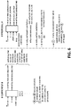
- Figure 6 shows a comparison between a control system and control method of a wind farm according to the state of the art and the control system and control method of a wind farm according to the present invention.
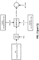
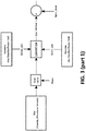
- Figures 4 and 5 show a general diagram of the control system and control method of a wind turbine of the present invention.
- the control system of the wind turbine is configured to calculate, based on an initial torque control Tref1 (or power Pref1) setpoint, a maximum reactive power limit desired (Lim_Q_Max_Des) which would allow not limiting the initial torque (or active power) control setpoint resulting from the control loops of the wind turbine and sending it to the control system of the wind farm.
- the initial torque (or power) control setpoint corresponds to a torque Tref1 (or power Pref1) setpoint to which limitations associated with at least one maximum electric capacity of a component of the electric drive (either of a generator or of a power converter) have not yet been applied; nonetheless, it can be limited based on the capacities of mechanical components.
- the generator and converter have different heating dynamics, with the power converter generally heating up more quickly than the generator, and therefore, they have a different capacity of withstanding currents greater than the rated current, capacity which will be dependent on the time when the current is greater than the rated current (which current can be withstood in steady-state).
- the step of calculating the maximum reactive power limit desired is performed when the operating conditions are such that the initial torque/active power control setpoint is greater than a maximum active power limit.
- the permanent maximum capacities of the generator and converter are used for calculating the at least one maximum reactive power limit desired.
- the control method additionally comprises the following steps:
- the reactive power setpoint Qrefi received from the control system of the wind farm (SGCS) will be sent to the control system of the power converter for the control of the generator.
Landscapes
- Engineering & Computer Science (AREA)
- Life Sciences & Earth Sciences (AREA)
- Sustainable Development (AREA)
- Sustainable Energy (AREA)
- Chemical & Material Sciences (AREA)
- Combustion & Propulsion (AREA)
- Mechanical Engineering (AREA)
- General Engineering & Computer Science (AREA)
- Power Engineering (AREA)
- Control Of Eletrric Generators (AREA)
- Supply And Distribution Of Alternating Current (AREA)
- Wind Motors (AREA)
Abstract
Description
- The present invention relates to a control system and a control method of a wind turbine configured for calculating an initial setpoint and sending it to the control system of a wind farm and receiving a final setpoint taking into account dynamic variations in the needs and possibilities of reactive power generation of said wind turbine with respect to maximum reactive power generation capacities based on the active power it can generate at all times.
- Normally, grid integration regulations stipulate as a requirement for connecting a wind farm to a power grid having available, under any condition of generating active power less than or equal to the rated power of the wind farm, a minimum reactive power generation capacity required in the wind farm to offer support to the power grid in the control of the voltage thereof. This in turn translates into minimum reactive power generation capacities required of the wind turbines of the wind farm in an individual manner, and as they are equipped with power converters, they are converted into a suitable solution for addressing the requirements of the grid operator, minimising the need for connecting additional equipment in the sub-station. Said reactive power capacity is referred to as minimum reactive power capacity required.
- Wind turbines have maximum electric capacities sized in turn by the minimum of the maximum capacities of the components of their electric drive (particularly generator and power converter). The maximum electric capacities are usually specified in terms of apparent power. Said maximum capacities provide an indication of the maximum active power and reactive power which the wind turbines can supply during a given time. Thus, there are often different values for the maximum rated electric capacity (i.e., that which can be sustained in a steady manner) than for transient maximum electric capacities (those which will only be sustained in a limited manner in time, for example, for less than ten minutes, one minute or several seconds). In turn, the maximum reactive power capacity required can be lower than the maximum reactive power capacity.
- The rated apparent power S determines the rated steady active power and reactive power levels that the wind turbines can generate without exceeding the rated current of the electrical elements that are part of the electric drive (primarily generator and converter). It is usually calculated with a rated active power value P and a rated reactive power value Q according to the following expression:

- In the state of the art, the rated reactive power and rated active power values determine the maximum active power and reactive power values which can be sustained in a steady manner, for which purpose those control systems responsible for calculating the active and reactive power setpoints of the wind turbines are configured so that said setpoints do not exceed said maximum values. That is, the control systems of the state of the art are configured such that the slow dynamics control loops will not calculate active power setpoints greater than the rated active power nor will they calculate reactive power setpoints greater than the rated reactive power. This occurs both in the wind farm and in the wind turbine (the control systems of the wind farm and of each wind turbine are configured as previously specified).
- Generally, the rated reactive power in the wind farm coincides with a minimum reactive power capacity required which must be guaranteed for compliance with grid integration codes applicable at the point of connection of the wind farm to the power grid.
- Reactive power is generally the control variable used for control of the voltage of the power grid. There are different control modes for controlling the voltage of the power grid, where it is generally the grid operator who specifies the most appropriate control mode in each case. Said operating modes coincide with different possible implementations in the control system of the wind farm for the control of reactive power:
- control of reactive power based on reactive power references received directly from a remote control centre (remote control centre which can belong to the wind farm operator or to the power grid operator);
- voltage control at a point of the power grid to which the wind farm is connected which, based on the voltage measurement taken at that point and on a voltage reference provided by the power grid operator (either directly or indirectly through the wind farm operator), calculates a global reactive power setpoint for the wind farm;
- control of the power factor at a point of the power grid to which the wind farm is connected which, based on the active power measurement taken at that point and on a power factor reference provided by the power grid operator (either directly or indirectly through the wind farm operator), calculates a global reactive power setpoint for the wind farm;
- Based on the power grid code or the control mode selected by the wind farm operator, the control system of the wind farm is configured to calculate a total reactive power setpoint for the wind farm which is later distributed in an individual manner among the different wind turbines to comply with the required setpoint. To that end, the control system of the wind farm calculates individual reactive power setpoints for the wind turbines which, when added together, amount to the total reactive power setpoint for the wind farm.
- There are solutions in the state of the art in which the control system of the wind farm performs the distribution either equally among the wind turbines of the wind farm, or it sends different setpoints for the wind turbines of the wind farm taking into consideration thermal or electric loss criteria, but always without exceeding a predetermined maximum reactive power capacity.
- The present invention relates to a control system and a control method of a wind turbine configured to generate an active power greater than the rated active power without exceeding the limit set by the apparent power, by means of calculating a desired maximum reactive power limit less than the rated reactive power, i.e., less than the minimum reactive power capacity required of the wind turbine.
- In the case of a wind turbine, the rated apparent power is set in the same way as in the state of the art. According to the invention, however, the steady active power may exceed the rated active power, for which the generated reactive power will be less than the rated reactive power.
- The maximum reactive power limit desired corresponds to the reactive power which can be generated without limitations in the active power. It is calculated based on an initial active power or torque setpoint to which electric limitations have not been applied and which is dependent on the operating conditions of the wind turbine (wind speed, temperature, capacity of the mechanical components) and on the rated apparent power. Said maximum reactive power limit desired is sent to a central wind farm control system for it to calculate a final reactive power setpoint, which once the maximum reactive power limits desired of each of the wind turbines with operating conditions that allow generating an active power greater than the rated active power have been taken into account, the control system will,send the final reactive power setpoint to each of them, in the attempt to keep it as close as possible to the available reactive power, without limitation, of each of them, i.e., to the respective maximum reactive power limits desired.
- Once the final reactive power setpoint has been received, the control system of the wind turbine will calculate a final torque or active power setpoint for the wind turbine which, taking into account the capacity of the electric drive, assures that there is available reactive power capacity to comply with the final reactive power setpoint received from the control system of the global reactive power setpoint in the wind farm. To that end, it will apply a maximum limit to the torque or initial power setpoint based on the final reactive power setpoint received from the control system of the wind farm and based on the capacity of the electric drive.
- In one embodiment, the steady reactive power can also exceed the rated reactive power.
- In a wind farm there can be wind turbines with different operating conditions:
- first wind turbines with operating conditions (wind speed and/or rotational speed, temperature of components, etc.) that give rise to initial active power or torque setpoints resulting from the control of the wind turbine which cannot be taken on without compromising the minimum reactive power capacities required, and
- second wind turbines with operating conditions (wind speed and/or rotational speed, temperature of components, etc.) that are such that the initial active power or torque setpoints resulting from the control of the wind turbine for said operating conditions can be taken on by the electric drive without compromising the minimum reactive power capacities required.
- This would be the case in situations in which the operating conditions of the second wind turbines are such that they cannot generate an active power greater than the rated active power (active power which can be generated in a sustained manner and simultaneously with the rated reactive power) and therefore be taken on by the electric drive without compromising the minimum reactive power capacities required, whereas the operating conditions of the first wind turbines are such that they can generate an active power greater than the rated active power provided that the capacity of the electric drive is assured to that end.
- For that purpose, the control system of at least one first wind turbine is configured to calculate a maximum reactive power limit desired which is a function of the initial active power or torque setpoint and of the capacity of the electric drive, and sending said maximum reactive power limit desired to the control system of the wind farm.
- This allows dedicating the highest possible fraction of the set of electric capacities (apparent power) of the wind farm to the active power generation such that given favorable wind conditions, the at least one first wind turbine may exceed the rated active power level.
- In order to satisfy a global reactive power setpoint of the wind farm, avoiding the necessity to limit the initial active power or torque setpoints resulting from the control of the first wind turbines, the control system of the wind farm is configured such that it can calculate the individual reactive power setpoints taking into account for the at least one first wind turbine at least one maximum reactive power limit desired.
- In the case of the first wind turbines, taking into account that the operating conditions of said wind turbines are such that they may exceed the rated active power level (that which can be provided in a sustained manner at the same time as the rated reactive power level), the maximum reactive power limit desired is lower than the maximum reactive power capacity required (which is equal to the rated reactive power in one embodiment).
- The control system and a control method of a wind turbine of the present invention is configured to calculate an initial active power setpoint based on which a maximum reactive power limit desired is calculated and sent to the control system of a wind farm, and receiving a final reactive power setpoint taking into account dynamic variations in the reactive power generation possibilities of said wind turbine with respect to maximum reactive power generation capacities. The invention also relates to the wind turbine comprising said control system of a wind turbine.
- On the other hand, the wind turbine must be configured in a suitable manner in order to achieve the correct operation of the control method of the wind farm:
Thus, the wind turbine is configured to calculate, based on an initial torque (or power) control setpoint, a maximum reactive power limit desired which would allow not limiting the initial torque (or active power) control setpoint resulting from the control loops of the wind turbine and sending it to the control system of the wind farm. The initial torque (or power) control setpoint corresponds to a torque (or power) setpoint to which limitations associated with the capacities of the electric drive have not yet been applied; nonetheless, it can be limited based on capacities of mechanical components. - Said maximum reactive power limits desired will be taken into account, as far as possible, by the control system of the wind farm when distributing the reactive power setpoints among the different wind turbines of the wind farm required for meeting, on a global level, the reactive power generation requirements of the power grid operator associated for example with controls of voltage at the point of connection of the farm to the power grid.
- The control system of a wind turbine of the present invention is configured to:
- calculate an initial torque/active power control setpoint desired based on the operating conditions of the wind turbine;
- calculate at least one maximum reactive power limit desired based on:
- at least one maximum electric capacity in the operating conditions of the wind turbine
- the initial torque/active power control setpoint desired,
- send the at least one maximum reactive power limit desired lower than a minimum reactive power capacity required to a central control system of the farm.
- Optionally, the control system is configured to calculate the maximum reactive power limit desired when the operating conditions are such that the initial torque/active power control setpoint is greater than a maximum active power limit.
- Optionally, when the operating conditions are such that the initial torque/active power control setpoint is not greater than the maximum active power limit, the control system is additionally configured to calculate a possible maximum reactive power limit based on:
- at least one maximum electric capacity in the operating conditions of the wind turbine
- the initial torque/active power control setpoint desired,
- send the at least one possible maximum reactive power limit to a central control system of the farm.
- Preferably, the at least one maximum electric capacity corresponds at least to a maximum electric capacity of a generator and to a maximum electric capacity of a power converter.
- The control system of the wind turbine is configured to operate the wind turbine according to different control modes wherein the wind turbine is enabled to generate an active power greater than the rated power for different time intervals: a mode in permanent regime (above 10 minutes), for a time of not more than 10 minutes or transient (for tenths of a second).
- Moreover, depending on the control mode of the wind turbine, i.e., the estimated time in which an above-normal active power is going to be generated, which may entail exceeding the at least one maximum electric capacity, the control system uses as a reference permanent maximum electric capacities or transient maximum capacities both for the generator and for the converter.
- Optionally, if the control mode of the generator is such that an active power level which could cause the rated apparent power in steady-state of the generator and/or converter to be exceeded is allowed (i.e., a Pref such that sprt(Pref^2+Qmax^2)>Sperm), the control system uses the permanent maximum capacities of the generator and converter for calculating the at least one maximum reactive power limit desired.
- Optionally, for controls in which the power can be increased such that sprt(Pref^2+Qmax^2)>Srated for a time of not more than 10 minutes, the control system takes into account a transient maximum capacity of the generator and a maximum capacity of the converter.
- Optionally, for controls in which the power can be increased above the rated power for a time of not more than tenths of a second, the control system takes into account a transient maximum capacity of the generator and a transient maximum capacity of the converter.
- Optionally, the control system is configured to additionally:
- receive a required reactive power setpoint from a control system of the wind farm (SGCS)
- calculate at least one maximum active power limit based on:
- the at least one maximum electric capacity in the operating conditions of the wind turbine;
- the reactive power setpoint received from the control system of the wind farm (SGCS);
- apply at least one maximum active power limit calculated in the step prior to the initial torque/active power control setpoint desired for calculating a final torque/active power control setpoint.
- Optionally, the at least one maximum electric capacity is of at least one of the following types:
- permanent
- transient (ten minutes)
- transient (seconds).
- The invention also refers to a control method of a wind turbine according to the above previously described, being the subject-matter of claims 11 to 20, here included by reference.
-
-
Figure 1 shows a general diagram of the control system and control method of a wind farm of the present invention. -
Figure 2 shows a block diagram of the control system and control method of a wind farm of the present invention. -
Figure 3 shows a block diagram of the calculation of reactive power setpoints with the system and according to the control method of a wind farm of the present invention. -
Figures 4 and5 show a general diagram of the control system and control method of a wind turbine of the present invention. -
Figure 6 shows a comparison between a control system and control method of a wind farm according to the state of the art and the control system and control method of a wind farm according to the present invention. -
Figure 1 shows a general diagram of the control system and control method of a wind farm of the present invention. Said figure shows that, based on the operating conditions (wind speed of each Vv_1,...,Vv_i, type of power curve enabled according to the mechanical limits, etc...), the wind turbines send to the control system of the wind farm SGCS information about reactive power generation needs (maximum reactive power limit desired, Lim_Q_max_des) and about reactive power generation possibilities (possible maximum reactive power limit, Lim_Q_max_pos) according to the available margin of the capacity of the electric drive and of the active power they can generate. The control system of the farm in turn sends to them, once said maximum reactive power limits desired and possible maximum reactive power limits have been taken into account, the individual reactive power setpoints Qref1, ..., Qrefi to be generated by the at least two wind turbines of the wind farm which will respect, as far as possible and depending on the global power setpoint Qref_global (which can be received by the SGCS or calculated by it based on the voltage measured at the point of connection of the wind farm to the grid POI), the maximum reactive power limits desired for maximising active power production of the wind farm. - The global power setpoint Qref_global can be received by the SGCS or calculated by it based on the voltage measured at the point of connection of the wind farm to the grid POI or of the power factor, according to the control that has been enabled so as to comply with the grid integration code.
- Thus, the control system of the wind farm of the invention is configured to:
- calculate a global reactive power setpoint (Qref_global) to be generated by the at least two wind turbines of the wind farm at the point of connection of the farm to the power grid;
- calculate individual reactive power setpoints (Qref1, ..., Qrefi) for each of the at least two wind turbines of the wind farm such that they add up to the global reactive power setpoint (Qref_global);
- receive from at least one first wind turbine of the wind turbines of the wind farm a maximum reactive power limit desired (Lim_Q_Max_Des) lower than a minimum reactive power capacity required of the wind turbine; and
- calculate the individual reactive power setpoints (Qref1, ..., Qrefi) for each of the at least two wind turbines of the wind farm such that the individual reactive power setpoint for the at least one first wind turbine of the wind farm does not exceed the maximum reactive power limit desired (Lim_Q_Max_Des).
-
Figure 2 shows a block diagram of the control system and control method of a wind farm of the present invention. Block C includes the detail of the system for calculating individual reactive power setpoints (reactive power individual dispatching) which would correspond toFigure 3 . The individual reactive power setpoint which is finally sent to the wind turbines Qrefi is a setpoint corrected Q_wtg_sp3 by means of adding the correction term Q_wtg_sp2 inFigure 3 to a the setpoint initially calculated Qwtg_sp1, taking into account the maximum reactive power limits possible and the maximum reactive power limits desired of the wind turbines. If it is possible to comply with the global setpoint of the farm with this first Q setpoint, the correction term Q_wtg_sp2 will have null value. - In particular, the calculation of the correction term for each of the initial reactive power setpoints of each wind turbine may be carried out in a proportional manner to the difference between the possible maximum reactive power limit and the desired maximum reactive power limit of each wind turbine.
-
Figure 3 shows a block diagram of the calculation of reactive power setpoints with the system and according to the control method of a wind farm of the present invention. In said figure there are two branches for calculating the Q setpoints for the wind turbines, depending on whether the global setpoint meets an inductive Q (Q g<0) or capacitive Q (Q>0) need. - As can be seen in
Figures 2 and3 , the control system of the wind farm of the invention is additionally configured to set at least one first reactive power limit (Qwtg_Avail_Cap_No P_Lim, Qwtg_Avail_Ind_No P_Lim,) for each of the wind turbines chosen from the maximum reactive power limit desired and the minimum reactive power capacity required, with the one chosen being the lowest in absolute value. - Since there are wind turbines with operating conditions that are such that they do not have the possibility of greater active power P generation, and therefore they do not have a maximum reactive power limit desired, two implementations are possible:
- all the wind turbines send the maximum reactive power limit desired, the control system of the wind turbine setting for those which do not have greater active power generation capacity (Pref1<Prated) the minimum reactive power capacity required for the wind turbine as a value for the first reactive power limit; or
- only those the wind turbines that do have greater active power generation capacity (Pref1<Prated) send the maximum reactive power limit desired, in which case the wind farm control system sets the minimum reactive power capacity required for the wind turbine, value which it has stored for each of the wind turbines of the wind farm, as a value for the first reactive power limit.
-
Figure 6 shows a comparison between a control system and control method of a wind farm according to the state of the art and the control system and control method of a wind farm according to the present invention. -
Figures 4 and5 show a general diagram of the control system and control method of a wind turbine of the present invention. - Thus, the control system of the wind turbine is configured to calculate, based on an initial torque control Tref1 (or power Pref1) setpoint, a maximum reactive power limit desired (Lim_Q_Max_Des) which would allow not limiting the initial torque (or active power) control setpoint resulting from the control loops of the wind turbine and sending it to the control system of the wind farm. The initial torque (or power) control setpoint corresponds to a torque Tref1 (or power Pref1) setpoint to which limitations associated with at least one maximum electric capacity of a component of the electric drive (either of a generator or of a power converter) have not yet been applied; nonetheless, it can be limited based on the capacities of mechanical components.
- This is because the generator and converter have different heating dynamics, with the power converter generally heating up more quickly than the generator, and therefore, they have a different capacity of withstanding currents greater than the rated current, capacity which will be dependent on the time when the current is greater than the rated current (which current can be withstood in steady-state).
- In one embodiment, the step of calculating the maximum reactive power limit desired is performed when the operating conditions are such that the initial torque/active power control setpoint is greater than a maximum active power limit.
- Depending on the control mode of the wind turbine (on the dynamics of the control loops of the wind turbine), i.e., the estimated time in which an above-normal active power is going to be generated (which may entail exceeding the at least one maximum electric capacity), permanent maximum electric capacities or transient maximum capacities both for the generator and for the converter will be used as a reference. In the particular case of slow dynamics corresponding to steady control, said maximum active power limit corresponds with the rated active power Prated.
- If the control mode of the generator is such that an active power level which could cause the rated apparent power of the generator and/or converter to be exceeded in steady-state (i.e., a Pref1 such that sqrt(Pref^2+Qmax^2)>Srated) is allowed, the permanent maximum capacities of the generator and converter are used for calculating the at least one maximum reactive power limit desired.
- The calculation will be performed as follows:

- The control method additionally comprises the following steps:
- receiving a reactive power setpoint required Qrefi from a control system of the wind farm (SGCS)
- calculating at least one maximum active power limit LimP2 based on:
- a. The at least one maximum electric capacity (it will be either transient or permanent) in the operating conditions of the wind turbine
- b. The reactive power setpoint received from the control system of the wind farm (SGCS) (Qrefi)
- Applying at least one maximum active power limit calculated in the step prior to the initial torque/active power control setpoint desired for calculating a final torque/active power control setpoint (Tref2 or Pref2).
- The at least one maximum active power limit LimP2 will be calculated in one embodiment as follows:

- The reactive power setpoint Qrefi received from the control system of the wind farm (SGCS) will be sent to the control system of the power converter for the control of the generator.
- If PTref1 <Prated, it is calculated a Lim_Qmax_pos > (Qrated=wind turbine minimum required capacity). On the contrary, if the operation conditions are such that PTref1<Prated, it is calculated a Lim_Qmax_des<Qrated, in order to benefit from the electrical capacity to generate power.
Claims (20)
- A control system for a wind turbine characterised in that it is configured to:• calculate an initial torque/active power control setpoint desired based on the operating conditions of the wind turbine;• calculate at least one maximum reactive power limit desired based on:at least one maximum electric capacity in the operating conditions of the wind turbinethe initial torque/active power control setpoint desired,such that it is not necessary to apply limitations to the initial torque/active power control setpoint desired and the at least one maximum electric capacity is not exceeded;• send the at least one maximum reactive power limit desired lower than a minimum reactive power capacity required to a central control system of the farm.
- The control system for a wind turbine according to claim 1, characterised in that it is configured to calculate the maximum reactive power limit desired when the operating conditions are such that the initial torque/active power control setpoint is greater than a maximum active power limit.
- The control system for a wind turbine according to claim 1, characterised in that when the operating conditions are such that the initial torque/active power control setpoint is not greater than the maximum active power limit, the system is additionally configured to calculate a possible maximum reactive power limit based on:at least one maximum electric capacity in the operating conditions of the wind turbinethe initial torque/active power control setpoint desired,such that it is not necessary to apply limitations to the initial torque/active power control setpoint desired and the at least one maximum electric capacity is not exceeded;• send the at least one possible maximum reactive power limit to a central control system of the farm.
- The control system for a wind turbine according to claim 2, characterised in that the at least one maximum electric capacity corresponds at least to a maximum electric capacity of a generator and to a maximum electric capacity of a power converter.
- The control system for a wind turbine according to claim 4, characterised in that, depending on the control mode of the wind turbine, namely the estimated time in which an above-normal active power is going to be generated, which may entail exceeding the at least one maximum electric capacity, the control system uses as a reference permanent maximum electric capacities or transient maximum capacities both for the generator and for the converter.
- The control system for a wind turbine according any one of claims 1 to 5 characterised in that, if the control mode of the generator is such that an active power level which could cause the rated apparent power in steady-state of the generator and/or converter to be exceeded is allowed (i.e., a Pref such that sprt(Pref^2+Qmax^2)>Sperm), the control system uses the permanent maximum capacities of the generator and converter for calculating the at least one maximum reactive power limit desired.
- The control system for a wind turbine according to claim 2, characterised in that for controls in which the power can be increased such that sprt(Pref^2+Qmax^2)>Srated for a time of not more than 10 minutes, the control system takes into account a transient maximum capacity of the generator and a permanent maximum capacity of the converter.
- The control system for a wind turbine according to any of claims 1 to 5, characterised in that for controls in which the power can be increased above the rated power for a time of not more than tenths of a second, the control system takes into account a transient maximum capacity of the generator and a permanent maximum capacity of the converter.
- The control system for a wind turbine according to any one of claims 1 to 7 characterised in that the control system is configured to additionally:• receive a required reactive power setpoint from a control system of the wind farm (SGCS)• calculate at least one maximum active power limit based on:the at least one maximum electric capacity in the operating conditions of the wind turbine;the reactive power setpoint received from the control system of the wind farm (SGCS);• apply at least one maximum active power limit calculated in the step prior to the initial torque/active power control setpoint desired for calculating a final torque/active power control setpoint.
- The control system for a wind turbine according to claim 3, characterised in that the at least one maximum electric capacity is of at least one of the following types:• permanent• transient (ten minutes)• transient (seconds).
- A control method of a wind turbine comprising the following steps:• calculating an initial torque/active power control setpoint desired based on the operating conditions of the wind turbine;• calculating at least one maximum reactive power limit desired based on:at least one maximum electric capacity in the operating conditions of the wind turbinethe initial torque/active power control setpoint desired,such that it is not necessary to apply limitations to the initial torque/active power control setpoint desired and the at least one maximum electric capacity is not exceeded;• sending the at least one maximum reactive power limit desired lower than a minimum reactive power capacity required to a central control system of the farm.
- Control method of a wind turbine according to claim 11, characterised in that the step of calculating the maximum reactive power limit desired is performed when the operating conditions are such that the initial torque/active power control setpoint is greater than a maximum active power limit.
- Control method of a wind turbine according to claim 11, characterised in that when the operating conditions are such that the initial torque/active power control setpoint is not greater than the maximum active power limit it additionally comprises the step of calculating a possible maximum reactive power limit based on:at least one maximum electric capacity in the operating conditions of the wind turbinethe initial torque/active power control setpoint desired,such that it is not necessary to apply limitations to the initial torque/active power control setpoint desired and the at least one maximum electric capacity is not exceeded;• send the at least one possible maximum reactive power limit to a central control system of the farm.
- Control method of a wind turbine according to claim 12, characterised in that the at least one maximum electric capacity corresponds at least to a maximum electric capacity of a generator and to a maximum electric capacity of a power converter.
- Control method of a wind turbine according to claim 14, characterised in that depending on the control mode of the wind turbine, i.e., the estimated time in which an above-normal active power is going to be generated, which may entail exceeding the at least one maximum electric capacity, permanent maximum electric capacities or transient maximum capacities both for the generator and for the converter will be used as a reference.
- Control method of a wind turbine according to any of claims 11 to 15, characterised in that if the control mode of the generator is such that an active power level which could cause the rated apparent power in steady-state of the generator and/or converter to be exceeded is allowed, namely a Pref such that sprt(Pref^2+Qmax^2)>Sperm, the permanent maximum capacities of the generator and converter are used for calculating the at least one maximum reactive power limit desired.
- Control method of a wind turbine according to claim 12, characterised in that for controls in which the power can be increased such that sprt(Pref^2+Qmax^2)>Srated for a time of not more than 10 minutes, a transient maximum capacity of the generator and a permanent maximum capacity of the converter are taken into account.
- Control method of a wind turbine according to any of claims 11 to 15, characterised in that for controls in which the power can be increased above the rated power for a time of not more than tenths of a second, a transient maximum capacity of the generator and a permanent maximum capacity of the converter are taken into account.
- Control method of a wind turbine according to any of claims 11 to 17, characterised in that it additionally comprises the following steps:• receiving a required reactive power setpoint from a control system of the wind farm (SGCS)• calculating at least one maximum active power limit based on:the at least one maximum electric capacity in the operating conditions of the wind turbinethe reactive power setpoint received from the control system of the wind farm (SGCS)• applying at least one maximum active power limit calculated in the step prior to the initial torque/active power control setpoint desired for calculating a final torque/active power control setpoint.
- Control method of a wind turbine according to claim 13, characterised in that the at least one maximum electric capacity is of at least one of the following types:• Permanent• Transient (ten minutes)• Transient (seconds).
Applications Claiming Priority (1)
| Application Number | Priority Date | Filing Date | Title |
|---|---|---|---|
| EP18383010 | 2018-12-31 |
Publications (1)
| Publication Number | Publication Date |
|---|---|
| EP3675310A1 true EP3675310A1 (en) | 2020-07-01 |
Family
ID=67437005
Family Applications (2)
| Application Number | Title | Priority Date | Filing Date |
|---|---|---|---|
| EP19383222.7A Pending EP3675310A1 (en) | 2018-12-31 | 2019-12-31 | Wind turbine control system and associated method |
| EP19383220.1A Pending EP3675309A1 (en) | 2018-12-31 | 2019-12-31 | Wind farm control system and associated method |
Family Applications After (1)
| Application Number | Title | Priority Date | Filing Date |
|---|---|---|---|
| EP19383220.1A Pending EP3675309A1 (en) | 2018-12-31 | 2019-12-31 | Wind farm control system and associated method |
Country Status (3)
| Country | Link |
|---|---|
| US (2) | US11326578B2 (en) |
| EP (2) | EP3675310A1 (en) |
| AU (1) | AU2019284124B2 (en) |
Families Citing this family (3)
| Publication number | Priority date | Publication date | Assignee | Title |
|---|---|---|---|---|
| JP2019532206A (en) * | 2016-08-09 | 2019-11-07 | エムエイチアイ ヴェスタス オフショア ウィンド エー/エス | Wind turbine control method and system |
| AU2019284124B2 (en) | 2018-12-31 | 2025-08-14 | Nordex Energy Spain, S.A.U. | Wind Farm Control System and Associated Method, Wind Turbine Control System and Associated Method |
| CN114593020A (en) * | 2022-01-24 | 2022-06-07 | 国电联合动力技术有限公司 | Wind turbine blade icing monitoring and early warning method, device and electronic equipment |
Citations (1)
| Publication number | Priority date | Publication date | Assignee | Title |
|---|---|---|---|---|
| US20100025994A1 (en) * | 2008-07-29 | 2010-02-04 | General Electric Company | Intra-area master reactive controller for tightly coupled windfarms |
Family Cites Families (8)
| Publication number | Priority date | Publication date | Assignee | Title |
|---|---|---|---|---|
| ES2327484B1 (en) * | 2008-01-22 | 2010-08-03 | Acciona Windpower S,A, | SYSTEM AND METHOD OF CONTROL OF A WIND FARM. |
| ES2771073T3 (en) * | 2010-08-02 | 2020-07-06 | Ge Renewable Tech Wind Bv | Reactive power regulation of a wind farm |
| JP5627529B2 (en) * | 2011-04-01 | 2014-11-19 | 三菱重工業株式会社 | Wind turbine generator control device, wind turbine generator, wind farm, and wind turbine generator control method |
| EP2565442A1 (en) * | 2011-09-05 | 2013-03-06 | Siemens Aktiengesellschaft | System and method for operating a wind turbine using adaptive reference variables |
| US9780710B2 (en) * | 2014-04-15 | 2017-10-03 | General Electric Company | Reactive power control for wind turbine generators |
| ES2818132T3 (en) * | 2015-06-30 | 2021-04-09 | Vestas Wind Sys As | Forecast-based wind turbine control |
| US11031784B2 (en) * | 2018-02-15 | 2021-06-08 | General Electric Company | Reactive current margin regulator for power systems |
| AU2019284124B2 (en) | 2018-12-31 | 2025-08-14 | Nordex Energy Spain, S.A.U. | Wind Farm Control System and Associated Method, Wind Turbine Control System and Associated Method |
-
2019
- 2019-12-28 AU AU2019284124A patent/AU2019284124B2/en active Active
- 2019-12-31 EP EP19383222.7A patent/EP3675310A1/en active Pending
- 2019-12-31 US US16/731,594 patent/US11326578B2/en active Active
- 2019-12-31 EP EP19383220.1A patent/EP3675309A1/en active Pending
- 2019-12-31 US US16/731,626 patent/US11448185B2/en active Active
Patent Citations (1)
| Publication number | Priority date | Publication date | Assignee | Title |
|---|---|---|---|---|
| US20100025994A1 (en) * | 2008-07-29 | 2010-02-04 | General Electric Company | Intra-area master reactive controller for tightly coupled windfarms |
Also Published As
| Publication number | Publication date |
|---|---|
| AU2019284124B2 (en) | 2025-08-14 |
| US11326578B2 (en) | 2022-05-10 |
| AU2019284124A1 (en) | 2020-07-16 |
| US11448185B2 (en) | 2022-09-20 |
| US20200217299A1 (en) | 2020-07-09 |
| EP3675309A1 (en) | 2020-07-01 |
| US20200220358A1 (en) | 2020-07-09 |
Similar Documents
| Publication | Publication Date | Title |
|---|---|---|
| US9677540B2 (en) | System and method for providing yaw backup to a wind farm | |
| EP2254217B1 (en) | Reactive Power Control for Operating a Wind Farm | |
| US11286904B2 (en) | Method of controlling a wind turbine generator | |
| EP2393179B1 (en) | System and process for controlling active power in a power generation plant | |
| EP2553788B1 (en) | Method of operating a wind turbine, wind turbine, wind turbine controlling system, and processing system | |
| US11448185B2 (en) | Control system of a wind turbine and associated method | |
| EP2256341B2 (en) | System and method for controlling a wind farm | |
| EP2693589B1 (en) | Wind park control system | |
| EP2317135A1 (en) | Wind turbine control method | |
| US11098694B2 (en) | Method of controlling a wind turbine generator | |
| CN114747111B (en) | Active power control in renewable power stations for grid stability | |
| CA2696839A1 (en) | Wind turbine generator system and operation control method therefor | |
| EP3669433B1 (en) | Improvements relating to reactive power control in wind power plants | |
| EP2932093B1 (en) | Method and arrangement for swift power regulation | |
| KR20160037239A (en) | Method for controlling wind turbines | |
| EP2757250A1 (en) | Wind farm output control device and output control method | |
| JP2019532206A (en) | Wind turbine control method and system | |
| RU2706861C1 (en) | Method for outputting a predetermined value of a control for an energy generator, a device for its implementation and a system with such a device | |
| US11271403B2 (en) | Method for operating a wind power facility | |
| JP2002291112A (en) | Method and apparatus for generating current value dependent on accelerator pedal position | |
| US8190300B2 (en) | Method for the operation of a wind farm | |
| CN111095715A (en) | Improvements relating to voltage control within wind power plants | |
| US20250369421A1 (en) | Method for providing a reactive power by way of a wind farm containing multiple wind power installations | |
| JP2026007727A (en) | Power system and power facility | |
| JP2022155264A (en) | Power supply management system, fuel cell device, and charging and discharging device |
Legal Events
| Date | Code | Title | Description |
|---|---|---|---|
| PUAI | Public reference made under article 153(3) epc to a published international application that has entered the european phase |
Free format text: ORIGINAL CODE: 0009012 |
|
| STAA | Information on the status of an ep patent application or granted ep patent |
Free format text: STATUS: THE APPLICATION HAS BEEN PUBLISHED |
|
| AK | Designated contracting states |
Kind code of ref document: A1 Designated state(s): AL AT BE BG CH CY CZ DE DK EE ES FI FR GB GR HR HU IE IS IT LI LT LU LV MC MK MT NL NO PL PT RO RS SE SI SK SM TR |
|
| AX | Request for extension of the european patent |
Extension state: BA ME |
|
| STAA | Information on the status of an ep patent application or granted ep patent |
Free format text: STATUS: REQUEST FOR EXAMINATION WAS MADE |
|
| 17P | Request for examination filed |
Effective date: 20201218 |
|
| RBV | Designated contracting states (corrected) |
Designated state(s): AL AT BE BG CH CY CZ DE DK EE ES FI FR GB GR HR HU IE IS IT LI LT LU LV MC MK MT NL NO PL PT RO RS SE SI SK SM TR |
|
| STAA | Information on the status of an ep patent application or granted ep patent |
Free format text: STATUS: EXAMINATION IS IN PROGRESS |
|
| 17Q | First examination report despatched |
Effective date: 20210511 |
|
| P01 | Opt-out of the competence of the unified patent court (upc) registered |
Effective date: 20230530 |
|
| GRAP | Despatch of communication of intention to grant a patent |
Free format text: ORIGINAL CODE: EPIDOSNIGR1 |
|
| STAA | Information on the status of an ep patent application or granted ep patent |
Free format text: STATUS: GRANT OF PATENT IS INTENDED |