EP3675308B1 - An active power curtailment management system - Google Patents
An active power curtailment management system Download PDFInfo
- Publication number
- EP3675308B1 EP3675308B1 EP19187442.9A EP19187442A EP3675308B1 EP 3675308 B1 EP3675308 B1 EP 3675308B1 EP 19187442 A EP19187442 A EP 19187442A EP 3675308 B1 EP3675308 B1 EP 3675308B1
- Authority
- EP
- European Patent Office
- Prior art keywords
- phase
- apc
- data
- inverter
- rooftop
- Prior art date
- Legal status (The legal status is an assumption and is not a legal conclusion. Google has not performed a legal analysis and makes no representation as to the accuracy of the status listed.)
- Active
Links
Images




Classifications
-
- H—ELECTRICITY
- H02—GENERATION; CONVERSION OR DISTRIBUTION OF ELECTRIC POWER
- H02J—ELECTRIC POWER NETWORKS; CIRCUIT ARRANGEMENTS OR SYSTEMS FOR SUPPLYING OR DISTRIBUTING ELECTRIC POWER; SYSTEMS FOR STORING ELECTRIC ENERGY
- H02J3/00—Circuit arrangements for AC mains or AC distribution networks
- H02J3/38—Arrangements for feeding a single network from two or more generators or sources in parallel; Arrangements for feeding already energised networks from additional generators or sources in parallel
- H02J3/381—Dispersed generators
-
- H—ELECTRICITY
- H02—GENERATION; CONVERSION OR DISTRIBUTION OF ELECTRIC POWER
- H02J—ELECTRIC POWER NETWORKS; CIRCUIT ARRANGEMENTS OR SYSTEMS FOR SUPPLYING OR DISTRIBUTING ELECTRIC POWER; SYSTEMS FOR STORING ELECTRIC ENERGY
- H02J2101/00—Supply or distribution of decentralised, dispersed or local electric power generation
- H02J2101/20—Dispersed power generation using renewable energy sources
- H02J2101/22—Solar energy
- H02J2101/24—Photovoltaics
-
- H—ELECTRICITY
- H02—GENERATION; CONVERSION OR DISTRIBUTION OF ELECTRIC POWER
- H02J—ELECTRIC POWER NETWORKS; CIRCUIT ARRANGEMENTS OR SYSTEMS FOR SUPPLYING OR DISTRIBUTING ELECTRIC POWER; SYSTEMS FOR STORING ELECTRIC ENERGY
- H02J2105/00—Networks for supplying or distributing electric power characterised by their spatial reach or by the load
- H02J2105/40—Networks for supplying or distributing electric power characterised by their spatial reach or by the load characterised by the loads connecting to the networks or being supplied by the networks
- H02J2105/42—Home appliances
-
- Y—GENERAL TAGGING OF NEW TECHNOLOGICAL DEVELOPMENTS; GENERAL TAGGING OF CROSS-SECTIONAL TECHNOLOGIES SPANNING OVER SEVERAL SECTIONS OF THE IPC; TECHNICAL SUBJECTS COVERED BY FORMER USPC CROSS-REFERENCE ART COLLECTIONS [XRACs] AND DIGESTS
- Y02—TECHNOLOGIES OR APPLICATIONS FOR MITIGATION OR ADAPTATION AGAINST CLIMATE CHANGE
- Y02B—CLIMATE CHANGE MITIGATION TECHNOLOGIES RELATED TO BUILDINGS, e.g. HOUSING, HOUSE APPLIANCES OR RELATED END-USER APPLICATIONS
- Y02B10/00—Integration of renewable energy sources in buildings
- Y02B10/10—Photovoltaic [PV]
-
- Y—GENERAL TAGGING OF NEW TECHNOLOGICAL DEVELOPMENTS; GENERAL TAGGING OF CROSS-SECTIONAL TECHNOLOGIES SPANNING OVER SEVERAL SECTIONS OF THE IPC; TECHNICAL SUBJECTS COVERED BY FORMER USPC CROSS-REFERENCE ART COLLECTIONS [XRACs] AND DIGESTS
- Y02—TECHNOLOGIES OR APPLICATIONS FOR MITIGATION OR ADAPTATION AGAINST CLIMATE CHANGE
- Y02B—CLIMATE CHANGE MITIGATION TECHNOLOGIES RELATED TO BUILDINGS, e.g. HOUSING, HOUSE APPLIANCES OR RELATED END-USER APPLICATIONS
- Y02B70/00—Technologies for an efficient end-user side electric power management and consumption
- Y02B70/30—Systems integrating technologies related to power network operation and communication or information technologies for improving the carbon footprint of the management of residential or tertiary loads, i.e. smart grids as climate change mitigation technology in the buildings sector, including also the last stages of power distribution and the control, monitoring or operating management systems at local level
-
- Y—GENERAL TAGGING OF NEW TECHNOLOGICAL DEVELOPMENTS; GENERAL TAGGING OF CROSS-SECTIONAL TECHNOLOGIES SPANNING OVER SEVERAL SECTIONS OF THE IPC; TECHNICAL SUBJECTS COVERED BY FORMER USPC CROSS-REFERENCE ART COLLECTIONS [XRACs] AND DIGESTS
- Y02—TECHNOLOGIES OR APPLICATIONS FOR MITIGATION OR ADAPTATION AGAINST CLIMATE CHANGE
- Y02B—CLIMATE CHANGE MITIGATION TECHNOLOGIES RELATED TO BUILDINGS, e.g. HOUSING, HOUSE APPLIANCES OR RELATED END-USER APPLICATIONS
- Y02B70/00—Technologies for an efficient end-user side electric power management and consumption
- Y02B70/30—Systems integrating technologies related to power network operation and communication or information technologies for improving the carbon footprint of the management of residential or tertiary loads, i.e. smart grids as climate change mitigation technology in the buildings sector, including also the last stages of power distribution and the control, monitoring or operating management systems at local level
- Y02B70/3225—Demand response systems, e.g. load shedding, peak shaving
-
- Y—GENERAL TAGGING OF NEW TECHNOLOGICAL DEVELOPMENTS; GENERAL TAGGING OF CROSS-SECTIONAL TECHNOLOGIES SPANNING OVER SEVERAL SECTIONS OF THE IPC; TECHNICAL SUBJECTS COVERED BY FORMER USPC CROSS-REFERENCE ART COLLECTIONS [XRACs] AND DIGESTS
- Y02—TECHNOLOGIES OR APPLICATIONS FOR MITIGATION OR ADAPTATION AGAINST CLIMATE CHANGE
- Y02E—REDUCTION OF GREENHOUSE GAS [GHG] EMISSIONS, RELATED TO ENERGY GENERATION, TRANSMISSION OR DISTRIBUTION
- Y02E10/00—Energy generation through renewable energy sources
- Y02E10/50—Photovoltaic [PV] energy
- Y02E10/56—Power conversion systems, e.g. maximum power point trackers
-
- Y—GENERAL TAGGING OF NEW TECHNOLOGICAL DEVELOPMENTS; GENERAL TAGGING OF CROSS-SECTIONAL TECHNOLOGIES SPANNING OVER SEVERAL SECTIONS OF THE IPC; TECHNICAL SUBJECTS COVERED BY FORMER USPC CROSS-REFERENCE ART COLLECTIONS [XRACs] AND DIGESTS
- Y02—TECHNOLOGIES OR APPLICATIONS FOR MITIGATION OR ADAPTATION AGAINST CLIMATE CHANGE
- Y02E—REDUCTION OF GREENHOUSE GAS [GHG] EMISSIONS, RELATED TO ENERGY GENERATION, TRANSMISSION OR DISTRIBUTION
- Y02E70/00—Other energy conversion or management systems reducing GHG emissions
- Y02E70/30—Systems combining energy storage with energy generation of non-fossil origin
-
- Y—GENERAL TAGGING OF NEW TECHNOLOGICAL DEVELOPMENTS; GENERAL TAGGING OF CROSS-SECTIONAL TECHNOLOGIES SPANNING OVER SEVERAL SECTIONS OF THE IPC; TECHNICAL SUBJECTS COVERED BY FORMER USPC CROSS-REFERENCE ART COLLECTIONS [XRACs] AND DIGESTS
- Y04—INFORMATION OR COMMUNICATION TECHNOLOGIES HAVING AN IMPACT ON OTHER TECHNOLOGY AREAS
- Y04S—SYSTEMS INTEGRATING TECHNOLOGIES RELATED TO POWER NETWORK OPERATION, COMMUNICATION OR INFORMATION TECHNOLOGIES FOR IMPROVING THE ELECTRICAL POWER GENERATION, TRANSMISSION, DISTRIBUTION, MANAGEMENT OR USAGE, i.e. SMART GRIDS
- Y04S20/00—Management or operation of end-user stationary applications or the last stages of power distribution; Controlling, monitoring or operating thereof
- Y04S20/20—End-user application control systems
- Y04S20/222—Demand response systems, e.g. load shedding, peak shaving
-
- Y—GENERAL TAGGING OF NEW TECHNOLOGICAL DEVELOPMENTS; GENERAL TAGGING OF CROSS-SECTIONAL TECHNOLOGIES SPANNING OVER SEVERAL SECTIONS OF THE IPC; TECHNICAL SUBJECTS COVERED BY FORMER USPC CROSS-REFERENCE ART COLLECTIONS [XRACs] AND DIGESTS
- Y04—INFORMATION OR COMMUNICATION TECHNOLOGIES HAVING AN IMPACT ON OTHER TECHNOLOGY AREAS
- Y04S—SYSTEMS INTEGRATING TECHNOLOGIES RELATED TO POWER NETWORK OPERATION, COMMUNICATION OR INFORMATION TECHNOLOGIES FOR IMPROVING THE ELECTRICAL POWER GENERATION, TRANSMISSION, DISTRIBUTION, MANAGEMENT OR USAGE, i.e. SMART GRIDS
- Y04S20/00—Management or operation of end-user stationary applications or the last stages of power distribution; Controlling, monitoring or operating thereof
- Y04S20/20—End-user application control systems
- Y04S20/242—Home appliances
Definitions
- the present invention is related to the problem of Active Power Curtailment (APC) in single/multiple-phase photovoltaic (PV) systems.
- APC Active Power Curtailment
- the inverter in a grid-connected single/multiple-phase PV system fails to inject active power into the low voltage distribution network due to the violation of network voltage upper limit (e.g. 1.10 per unit or 253 V in Belgium), which leads to a loss of PV power. Therefore, the main focus of the present invention is to minimize this PV power loss to zero by providing a solution/system in order to prevent or reduce APC of such single/multiple-phase PV systems.
- phase voltages plays an important role, which increases with the increase in the distance from the substation transformer in a low voltage distribution network (refer Fig. 2 ). This means that the phase voltages near the end of distribution network are far more sensitive and susceptible to changes with the active power injected or drawn as compared to near the substation transformer.
- APC The duration of APC ranges from 8% to 15% of the total PV power production hours in a year. In Belgium, it accounts for 80 to 150 hours of APC per year, which is a significant amount of PV power curtailed because of which single-phase rooftop PV system homeowners suffer from the decrease in return on investment (ROI).
- Distribution network phase voltage balancing systems for maintaining a balanced load condition in response to variations in the load applied to one or more phases of a multi-phase system are for example known from US2652529 , DE102009060364 , CN104333035 , Sam Weckx et al. (S. Weckx and J. Driesen, "Load Balancing With EV Chargers and PV Inverters in Unbalanced Distribution Grids," in IEEE Transactions on Sustainable Energy, vol. 6, no. 2, pp. 635-643, April 2015, doi: 10.1109/TSTE.2015.2402834 ) or WO2012175332 .
- CN104333035 provides a system capable of restraining network voltage imbalance by automatically output compensating current.
- Sam Weckx et al. proposes three-phase balancing inverters and off-board three phase Electric Vehicle (EV) chargers in a distribution network to improve network voltage conditions by absorbing power from a phase with a lower loading and injecting into the phase with the highest loading.
- EV Electric Vehicle
- These balancing inverters and offboard EV chargers are additional components compared to the single-phase PV inverters and chargers typically found in homes which distribute the current among three phases.
- Sam Weckx et al. objective is to balance the network voltage.
- US 2652529 patent deals with phase balancing system by energizing a capacitive reactance, an inductive reactance and a variable single-phase load from different phase conductors of three-phase system.
- WO2017193172A1 relates to predicting a level of solar radiation, such as a solar irradiance or power. For example, the predicted solar irradiance can be used for controlling solar power systems.
- US2010076613A1 relates generally to energy management systems. More specifically, the present disclosure relates to a system, method, and module capable of curtailing energy production within congestive grid operating environments.
- US2017250540A1 relates to power generation facilities. More specifically, the present invention provides methods and systems for operating a power generation facility such as a photovoltaic (PV) solar farm.
- PV photovoltaic
- Bunaiyan "Photovoltaic inverter dispatch for voltage regulation in power distribution systems: A comparative evaluation," 2016 North American Power Symposium (NAPS), 2016, pp. 1-6, doi: 10.1109/NAPS.2016.7747976 ) relates to a comparative evaluation of methods for choosing the PV inverter set-points, comparing local decentralized methods to a variety of optimal power flow-based algorithms. Utility concerns, namely voltage regulation and line losses, are balanced against the customer concerns of maximum profit from owned PV systems.
- the present invention provides a system to manage that curtailed active power that can be utilized by using one or more of the following actions:
- an APC management system is provided to prevent or reduce APC in the inverter of a rooftop PV system, which are connected to low voltage distribution network, using household load(s), comprising;
- the microcontroller is preferably configured to use day-ahead PV output power forecast data to predict time and duration of APC in advance and take preemptive action by preparing the household load(s) beforehand to absorb the single/multiple-phase PV inverter output power during the APC.
- the microcontroller in the APC management system may be further configured to;
- the system receives information on phase voltage(s) of low voltage distribution network through the phase voltage input module.
- This module could be based on known phase voltage measurement unit(s) such as found in phase balancing system(s).
- the APC management system as herein provided is typically installed behind the meter and connected to a low voltage distribution network, including single-phase or multiple-phases, such as in a 3-phase low voltage distribution network.
- a low voltage distribution network including single-phase or multiple-phases, such as in a 3-phase low voltage distribution network.
- the system is connected to a multiple-phase distribution network; in particular a 3-phase distribution network it comprises;
- the APC management system may also comprise a plurality of secondary relay(s) each configured to connect or disconnect the single/multiple-phase rooftop PV system from a plurality of household load(s). The system can even enter into an off-grid mode wherein it is fully disconnected from the phases, thus providing full flexibility to the system in preventing and reducing APC to occur.
- the system can further comprise a curtailment handling (CH) inverter, a battery storage system and a remote central server, as shown in Fig. 6 and 7 .
- CH inverter will enable conversion of the grid-connected household network into an islanded grid/off-grid/nanogrid, i.e. a network with a small number of nodes like a household that can realize a functional islanded/off-grid by complete separation from the low voltage distribution network.
- the CH inverter is specifically configured to set the nominal voltage (e.g. 230 V rms) and a nominal frequency (e.g. 50 Hz) at its AC terminals when the single/multiple-phase rooftop PV system is disconnected from the voltage phases of the low voltage distribution network.
- the plurality of household load(s) within the context of the present invention could be any electric household device(s), which can use the curtailed active power when it occurs.
- Such household load(s) could for example be selected from a battery storage system, heating or cooling devices.
- SOC state of charge
- curtailed PV active power can be absorbed by said battery storage system during APC.
- the battery storage system can participate through the CH inverter in controlling the voltage and frequency of the islanded grid/off-grid/nanogrid in accordance with the nominal voltage and frequency e.g.
- the CH inverter 230 V rms and 50 Hz set by the CH inverter.
- the CH inverter will absorb the excess power produced into the battery storage system.
- the CH inverter will draw power from the battery storage system to maintain the voltage and frequency of the islanded grid/off-grid/nanogrid in accordance with the nominal voltage set by the CH inverter.
- the set temperature of the boiler can be lowered beforehand and curtailed PV active power can be utilized to boil the water by elevating the temperature in case an APC occurs.
- curtailed PV active power can be utilized to boil the water by elevating the temperature in case an APC occurs.
- a heat pump room or pool temperature can be adjusted to a lower or higher temperature and heating or refrigeration activated in case of APC events to tap curtailed PV active power.
- the system is configured to prepare the battery storage system and household load(s) in advance to absorb the curtailed PV active power in preventing or reducing the APC. As already mentioned hereinbefore, this adjustment is preferably based using day-ahead PV output power forecast data.
- the APC management system may be configured to use day-ahead PV output power forecast data to predict time and duration of APC in advance and take preemptive action by preparing the battery storage system and household load(s) beforehand to absorb the PV inverter output power during the APC in preventing or reducing the APC; more in particular, the microcontroller in an APC management system according to the invention is further characterized in being configured to use day-ahead PV output power forecast data to prepare the battery storage system and household load(s) in preventing or reducing the APC.
- the system makes use of actual PV power generation data, real-time PV inverter injected active power data and phase voltage input data.
- phase voltage input module yields the phase voltage input data
- real-time PV inverter injected active power data is directly available as an output from the ac terminal of PV inverter.
- Day-ahead PV output power forecast data and actual PV power generation data are for example available from a power grid system operator like Elia in Belgium. Said data are either the accumulated day-ahead PV output power forecast for the installed solar capacity of a country, region, network and the accumulated real-time actual PV power generation data for the installed solar capacity of a country, region, network.
- the day-ahead PV output power forecast data for the single/multiple-phase rooftop PV system are a downscale of said accumulated day-ahead PV output power forecast in accordance with the geographical location of said single/multiple-phase rooftop PV system.
- the actual PV power generation data for the single/multiple-phase rooftop PV system are a downscale of said accumulated real-time actual PV power generation data in accordance with the geographical location of said single/multiple-phase rooftop PV system.
- the presence of such remote central server allows for example to adjust the accumulated actual PV power generation data and the day-ahead PV output power forecast data in accordance with the geographical location and technical details of the local single/multiple-phase rooftop PV system before being transmitted to the microcontroller in the APC management system.
- the actual PV power generation data are directly transmitted to the microcontroller and adjusted in accordance with the geographical location and technical details of the local single/multiple-phase rooftop PV system by said microcontroller.
- the system further comprises communication means to receive actual PV power generation data and day-ahead PV output power forecast data from a remote central provider.
- the system further comprises a single/multiple-phase rooftop PV system data module configured to receive technical data of the single/multiple-phase rooftop PV system such as capacity, azimuth, inclination, and solar irradiation of the single/multiple-phase rooftop PV system. It will be evident that the aforementioned methods to adjust the accumulated actual PV generation data are equally applicable for the day-ahead PV output power forecast data available from such Power Grid transmission system operators.
- a method for APC management of a single/multiple-phase rooftop PV system comprising a single/multiple-phase PV inverter connected to any phase(s) of a low voltage distribution network; using a microcontroller connected to primary relay(s) configured to connect or disconnect the single/multiple-phase rooftop PV system from said phase(s); and connected to one or more secondary relay(s) configured to connect or disconnect the single/multiple-phase rooftop PV system from household load(s) in a household network, said method comprising
- the APC management system activates when both the network voltage violates its upper limit and there is a difference between the actual PV power generation data and the real-time PV inverter injected active power data where this difference is increasing rapidly with time such as for example that the rate of change of real-time PV inverter injected active power data is greater than 100, 200, 300, 400, or 500 W/minute.
- the microcontroller may send commands to the primary relay(s) to disconnect from said phase(s) and commands at least one of the secondary relays to connect to the household load(s) when the real-time PV inverter injected active power becomes unequal with actual PV power generation where this difference is increasing rapidly with time such that the rate of change of real-time PV inverter injected active power data is for example greater than 250 W/minute, in particular greater than 500 W/minute, and the phase voltage violates the network voltage upper limit.
- the microcontroller commands the primary relay(s) to disconnect from said phase(s) and commands at least one of the secondary relays to connect to the battery storage system and household load(s) when the phase voltage violates the network voltage upper limit, and the real-time PV inverter injected active power becomes unequal with actual PV power generation data and this difference is increasing rapidly with time such that the rate of change of real-time PV inverter injected active power data is for example greater than 500 W/minute, the system could enter into an islanded grid/off-grid/nanogrid mode.
- the microcontroller may further command a CH inverter present between the incoming phase(s) in a household and the battery storage system (refer Fig.
- the microcontroller may command the CH inverter to maintain the nominal voltage (e.g. 230 V rms) and the nominal frequency (e.g. 50 Hz) at its AC terminals, by injecting or drawing power to/from battery storage system present in the system and/or within the isolated household network.
- the nominal voltage e.g. 230 V rms
- the nominal frequency e.g. 50 Hz
- the method for APC management comprises
- the microcontroller commands the primary relay of the phase to which the PV inverter is connected to disconnect from said phase and commands one of the other primary relays to connect to the other phase of the 3-phase distribution network if the phase voltage of said other phase is below the network voltage upper limit; or commands at least one of the secondary relay(s) to connect to the battery storage system and household load(s) when the real-time PV inverter injected active power becomes unequal with actual PV power generation data where this difference is increasing rapidly with time such that the rate of change of real-time PV inverter injected active power data is for example greater than 500 W/minute and the phase voltage violates the network voltage upper limit.
- Day-ahead PV output power forecast data may be provided to the microcontroller, and used by said microcontroller to predict time and duration of APC in advance and take preemptive action by preparing the household load(s) beforehand to absorb the PV inverter output power during the APC in preventing or reducing the APC.
- the household load(s) preferably include battery storage system and at least one of the secondary relays is configured to connect or disconnect the single/multiple-phase rooftop PV system from such battery storage system.
- the microcontroller uses said day-ahead PV output power forecast data to prepare the battery storage system in preventing or reducing the APC by reducing the battery SOC.
- the actual PV power generation data and the day-ahead PV output power forecast data may be adjusted for the technical data of the single/multiple-phase rooftop PV system. This could be done either at a remote central server or by the microcontroller of the APC management system.
- adjustments can comprise:
- APC occurs when the phase voltages at the POI of PV inverter to the low voltage distribution network hits the network voltage upper limit (such as which is 10% above the nominal voltage of 230 V rms in Belgium i.e. 253 V rms or 1.10 per unit).
- the APC management system disclosed herein will monitor the phase voltages at the POI of PV inverter to the low voltage distribution network and based on actual PV power generation data and the real-time PV inverter injected active power data, the system is configured to determine whether APC occurs and to prevent or reduce such APC by dynamically disconnecting it from the phase(s) that is violating the network voltage upper limit such as 1.10 per unit or 253 V rms and re-connecting it to either of the voltage phases that is within the voltage limits; or household load(s) like battery storage system, heating or refrigerating device(s) to absorb the curtailed PV active power.
- the network voltage upper limit such as 1.10 per unit or 253 V rms
- the APC system disclosed herein is highly flexible and can even be implemented in single/multiple-phase rooftop PV systems connected through a single/multiple-phase with a low-voltage distribution network.
- the APC management system is configured to determine whether APC occurs as herein describes and prevents or reduces APC by commanding the secondary relay(s) configured to connect or disconnect the single/multiple-phase rooftop PV system from said household load(s).
- the rooftop PV system will be disconnected from the low voltage distribution network and entering an off-grid configuration wherein the PV inverter active power is either directly consumed through the household load(s) and/or stored in an electrical energy storage device such as a battery.
- the APC management system disclosed herein is highly modular in its possibilities of reducing or preventing the APC to occur. Not to be bound to a particular order of events, when the APC management system detects an APC event it will;
- the system relies on day-ahead PV output power forecast data to prepare household load(s) including battery storage system to act as energy buffers for such APC events.
- the phase voltage(s) hits the network voltage upper limit and the difference between the real-time PV inverter injected active power data and the actual PV power generation date changes rapidly, i.e. at a rate of more than 100 W/minute, in particular more than 500W/minute, the system can switch into a full islanded grid/off-grid/nanogrid mode injecting the PV active power into the pre-conditioned battery storage system and household load(s).
- the household network is isolated from the low voltage distribution network by opening the primary relays shown as S1 and S2 in Figures 6 and 7 .
- the household network will be operating in an islanded mode as a nanogrid requiring the presence of a so named curtailment handling (CH) inverter, a battery storage system and a remote central server.
- the curtailment handling (CH) inverter is a bidirectional inverter which constitutes the backbone of the system.
- the CH inverter is installed behind the meter between the battery storage system and incoming ac phase(s) in a household, as shown in Fig. 6 and Fig. 7 . It is capable of operating during all the possible modes of operation and receives commands from the microcontroller.
- the APC management system may further comprise a curtailment handling (CH) inverter.
- CH curtailment handling
- a battery storage system may be included, said battery storage preferably being connected with said CH inverter and optionally under direct operational control of the microcontroller. Therefore, an APC management system as herein described comprises, inter alia:
- determining whether APC occurs is still relying on the actual PV power generation data, real-time PV inverter injected active power data and phase voltage(s) input data as extensively described, but further characterized in that the CH inverter sets nominal voltage and frequency at its AC terminals when entering into islanded/off-grid/nanogrid mode.
Landscapes
- Engineering & Computer Science (AREA)
- Power Engineering (AREA)
- Supply And Distribution Of Alternating Current (AREA)
Description
- The present invention is related to the problem of Active Power Curtailment (APC) in single/multiple-phase photovoltaic (PV) systems. During the APC, the inverter in a grid-connected single/multiple-phase PV system fails to inject active power into the low voltage distribution network due to the violation of network voltage upper limit (e.g. 1.10 per unit or 253 V in Belgium), which leads to a loss of PV power. Therefore, the main focus of the present invention is to minimize this PV power loss to zero by providing a solution/system in order to prevent or reduce APC of such single/multiple-phase PV systems.
- Single/multiple-phase PV systems in low voltage distribution network suffer from the problem of APC when the phase voltages at the point of interconnection (POI) of PV inverter to the low voltage distribution network hit the network voltage upper limit (which is typically 10% above the nominal voltage of 230 V rms such as in Belgium i.e. 253 V rms or 1.10 per unit). This is more prominent among rooftop PV systems which are located near the end of the distribution network or far away from the substation transformer (refer
Fig. 1 ). This is because, in a low voltage distribution network, active power and phase voltages are directly related to each other in such a way that the phase voltages increase (overvoltage condition) with the increase in active power injection and decrease (under voltage condition) with the increase in active power drawn. Additionally, the sensitivity of phase voltages plays an important role, which increases with the increase in the distance from the substation transformer in a low voltage distribution network (referFig. 2 ). This means that the phase voltages near the end of distribution network are far more sensitive and susceptible to changes with the active power injected or drawn as compared to near the substation transformer. - With the rise in installation of single-phase rooftop PV systems and corresponding increase in active power injection in a low voltage distribution network, as shown in
Fig. 1 , the voltage of the electrical network at the POI of PV inverters also rises. On the other hand, the distribution system operators (DSO) like to maintain the phase voltages of low voltage distribution network typically between the operating limits such as 0.90 per unit (207 V rms) to 1.10 per unit (253 V rms) for safe and stable operation. Thus, to keep the phase voltages within the said limits, the inverters of such single-phase PV systems are shut down and their active power injection into the low voltage distribution network are curtailed (seeFig. 3 ). The duration of APC ranges from 8% to 15% of the total PV power production hours in a year. In Belgium, it accounts for 80 to 150 hours of APC per year, which is a significant amount of PV power curtailed because of which single-phase rooftop PV system homeowners suffer from the decrease in return on investment (ROI). - Distribution network phase voltage balancing systems for maintaining a balanced load condition in response to variations in the load applied to one or more phases of a multi-phase system are for example known from
US2652529 ,DE102009060364 ,CN104333035 , Sam Weckx et al. (S. Weckx and J. Driesen, "Load Balancing With EV Chargers and PV Inverters in Unbalanced Distribution Grids," in IEEE Transactions on Sustainable Energy, vol. 6, no. 2, pp. 635-643, April 2015, doi: 10.1109/TSTE.2015.2402834) orWO2012175332 .CN104333035 provides a system capable of restraining network voltage imbalance by automatically output compensating current. Sam Weckx et al. proposes three-phase balancing inverters and off-board three phase Electric Vehicle (EV) chargers in a distribution network to improve network voltage conditions by absorbing power from a phase with a lower loading and injecting into the phase with the highest loading. These balancing inverters and offboard EV chargers are additional components compared to the single-phase PV inverters and chargers typically found in homes which distribute the current among three phases. Sam Weckx et al. objective is to balance the network voltage.US 2652529 patent deals with phase balancing system by energizing a capacitive reactance, an inductive reactance and a variable single-phase load from different phase conductors of three-phase system. The patentDE102009060364 links the phase unbalance to charging of EVs, but is equally silent on active power curtailment management. The same holds true forWO2012175332 which is controlling the load of the phases of a three-phase system by means of a controllable switch element. -
WO2017193172A1 relates to predicting a level of solar radiation, such as a solar irradiance or power. For example, the predicted solar irradiance can be used for controlling solar power systems.US2010076613A1 relates generally to energy management systems. More specifically, the present disclosure relates to a system, method, and module capable of curtailing energy production within congestive grid operating environments.US2017250540A1 relates to power generation facilities. More specifically, the present invention provides methods and systems for operating a power generation facility such as a photovoltaic (PV) solar farm. Wiebe Daniel et al. (D. Wiebe, F. Mancilla-David, M. Carrasco and A. Bunaiyan, "Photovoltaic inverter dispatch for voltage regulation in power distribution systems: A comparative evaluation," 2016 North American Power Symposium (NAPS), 2016, pp. 1-6, doi: 10.1109/NAPS.2016.7747976) relates to a comparative evaluation of methods for choosing the PV inverter set-points, comparing local decentralized methods to a variety of optimal power flow-based algorithms. Utility concerns, namely voltage regulation and line losses, are balanced against the customer concerns of maximum profit from owned PV systems. - Where these prior art deal with improving the efficiency, reliability, and energy performance through balancing the network by measuring unbalance, switching single phase loads to the phase that is least loaded using current measurements, and distributing the current between lower and highest loaded phases, these system are not interested in using the available phase voltages to determine whether the active power injected by a single/multiple-phase PV inverter is restricted because of phase voltage limits, and to take the necessary measures in preventing such restriction in active power production to occur.
- It is an objective of the present invention to prevent or reduce APC of single/multiple-phase rooftop PV system because of the phase voltage limitation in low voltage distribution network. Thereto, and as further detailed hereinafter, the present invention provides a system to manage that curtailed active power that can be utilized by using one or more of the following actions:
- Injection into the low voltage distribution network by switching the POI of inverter of single-phase PV system between the phases,
- locally storage in an energy storage device like a battery by predicting time and duration of APC in advance and preparing the battery beforehand, and/ or
- consume in household load(s) like heating and/or refrigerating device(s) inside homes, by predicting time and duration of APC in advance and preconditioning said battery storage system and household load(s) so that they can act as energy buffers in the off-grid mode from low voltage distribution network comprising the PV system.
- The invention is set out in the appended set of claims. The embodiments and/or examples of the following description which are not covered by the appended claims are considered as not being part of the present invention.
- In a first example, an APC management system is provided to prevent or reduce APC in the inverter of a rooftop PV system, which are connected to low voltage distribution network, using household load(s), comprising;
- A phase voltage input module;
- A microcontroller;
- A primary relay configured to connect or disconnect the rooftop PV system from said phase(s); and
- A secondary relay configured to connect or disconnect the rooftop PV system from said household load(s);
- In order to enable full prevention of APC to occur, the microcontroller is preferably configured to use day-ahead PV output power forecast data to predict time and duration of APC in advance and take preemptive action by preparing the household load(s) beforehand to absorb the single/multiple-phase PV inverter output power during the APC. Thus the microcontroller in the APC management system may be further configured to;
- use day-ahead PV output power forecast data to predict time and duration of APC in advance and preconditioning said household load(s) so that they can act as energy buffers in the off-grid mode from low voltage distribution network comprising the PV system; and
- use actual PV power generation data, real-time PV inverter injected active power data and phase voltage(s) input data as an input to determine APC and to prevent or reduce APC by opening and/or closing of the primary and/or secondary relay(s)
- The system receives information on phase voltage(s) of low voltage distribution network through the phase voltage input module. This module could be based on known phase voltage measurement unit(s) such as found in phase balancing system(s).
- As mentioned herein before, the APC management system as herein provided is typically installed behind the meter and connected to a low voltage distribution network, including single-phase or multiple-phases, such as in a 3-phase low voltage distribution network. In said embodiments wherein the system is connected to a multiple-phase distribution network; in particular a 3-phase distribution network it comprises;
- a phase voltage input module for each phase; and
- a plurality of primary relay(s) configured to connect or disconnect the rooftop PV system to each of said phase(s).
- It follows from the foregoing that in case of multiple incoming phases in a household, a primary relay for each phase is preferable. Such configuration allows the system to dynamically switch between said phases. A similar degree of flexibility can equally be achieved in connecting or disconnecting the household load(s), in case said household loads are distributed over a plurality of secondary relay(s). Thus, the APC management system may also comprise a plurality of secondary relay(s) each configured to connect or disconnect the single/multiple-phase rooftop PV system from a plurality of household load(s). The system can even enter into an off-grid mode wherein it is fully disconnected from the phases, thus providing full flexibility to the system in preventing and reducing APC to occur. In said off-grid configuration the system can further comprise a curtailment handling (CH) inverter, a battery storage system and a remote central server, as shown in
Fig. 6 and7 . Such CH inverter will enable conversion of the grid-connected household network into an islanded grid/off-grid/nanogrid, i.e. a network with a small number of nodes like a household that can realize a functional islanded/off-grid by complete separation from the low voltage distribution network. Thereto the CH inverter is specifically configured to set the nominal voltage (e.g. 230 V rms) and a nominal frequency (e.g. 50 Hz) at its AC terminals when the single/multiple-phase rooftop PV system is disconnected from the voltage phases of the low voltage distribution network. - The plurality of household load(s) within the context of the present invention could be any electric household device(s), which can use the curtailed active power when it occurs. Such household load(s) could for example be selected from a battery storage system, heating or cooling devices. For example, in case of a battery storage system, by adjusting the state of charge (SOC) to a lower level in the evening when there is no PV power production, curtailed PV active power can be absorbed by said battery storage system during APC. In the off-grid mode the battery storage system can participate through the CH inverter in controlling the voltage and frequency of the islanded grid/off-grid/nanogrid in accordance with the nominal voltage and frequency e.g. 230 V rms and 50 Hz set by the CH inverter. As an example when during APC the rooftop PV inverter is generating more active power than the household load(s) demand, then the CH inverter will absorb the excess power produced into the battery storage system. On the contrary, when during APC the rooftop PV inverter is generating insufficient power and the islanded grid/off-grid/nanogrid voltage tends to decrease, the CH inverter will draw power from the battery storage system to maintain the voltage and frequency of the islanded grid/off-grid/nanogrid in accordance with the nominal voltage set by the CH inverter.
- For example, in case of a household heating device, such as a hot water boiler, the set temperature of the boiler can be lowered beforehand and curtailed PV active power can be utilized to boil the water by elevating the temperature in case an APC occurs. For example, in case of a heat pump room or pool temperature can be adjusted to a lower or higher temperature and heating or refrigeration activated in case of APC events to tap curtailed PV active power. It follows from the foregoing that as part of APC management, the system is configured to prepare the battery storage system and household load(s) in advance to absorb the curtailed PV active power in preventing or reducing the APC. As already mentioned hereinbefore, this adjustment is preferably based using day-ahead PV output power forecast data. The APC management system may be configured to use day-ahead PV output power forecast data to predict time and duration of APC in advance and take preemptive action by preparing the battery storage system and household load(s) beforehand to absorb the PV inverter output power during the APC in preventing or reducing the APC; more in particular, the microcontroller in an APC management system according to the invention is further characterized in being configured to use day-ahead PV output power forecast data to prepare the battery storage system and household load(s) in preventing or reducing the APC.
- In determining the occurrence of APC, the system makes use of actual PV power generation data, real-time PV inverter injected active power data and phase voltage input data. Where the phase voltage input module yields the phase voltage input data, and the real-time PV inverter injected active power data is directly available as an output from the ac terminal of PV inverter. Day-ahead PV output power forecast data and actual PV power generation data are for example available from a power grid system operator like Elia in Belgium. Said data are either the accumulated day-ahead PV output power forecast for the installed solar capacity of a country, region, network and the accumulated real-time actual PV power generation data for the installed solar capacity of a country, region, network. In its simplest form, the day-ahead PV output power forecast data for the single/multiple-phase rooftop PV system are a downscale of said accumulated day-ahead PV output power forecast in accordance with the geographical location of said single/multiple-phase rooftop PV system. In analogy, in its simplest form, the actual PV power generation data for the single/multiple-phase rooftop PV system are a downscale of said accumulated real-time actual PV power generation data in accordance with the geographical location of said single/multiple-phase rooftop PV system. A further refinement of the accumulated day-ahead PV output power forecast data and of the accumulated actual PV power generation data is possible by means of further technical data relevant for the local single/multiple-phase rooftop PV system. Such further technical data could for example include azimuth, inclination, and solar irradiation of the single/multiple-phase rooftop PV system.
- In accordance with the European regulator guideline, Power Grid transmission system operators like Elia in Belgium are not only obliged to provide actual PV power generation data, also day-ahead PV output power forecast data must be made available online. Consequently, the actual PV power generation data, as well as the day-ahead PV output power forecast data can be retrieved either directly or through a dedicated and remote central server of the APC management system.
- The presence of such remote central server, allows for example to adjust the accumulated actual PV power generation data and the day-ahead PV output power forecast data in accordance with the geographical location and technical details of the local single/multiple-phase rooftop PV system before being transmitted to the microcontroller in the APC management system. Alternatively, the actual PV power generation data are directly transmitted to the microcontroller and adjusted in accordance with the geographical location and technical details of the local single/multiple-phase rooftop PV system by said microcontroller. In either case, the system further comprises communication means to receive actual PV power generation data and day-ahead PV output power forecast data from a remote central provider.
- In order to enable that the system adjusts the actual PV power generation data and day-ahead PV output power forecast data based on the geographical location and technical details of the single/multiple-phase rooftop PV system, the system further comprises a single/multiple-phase rooftop PV system data module configured to receive technical data of the single/multiple-phase rooftop PV system such as capacity, azimuth, inclination, and solar irradiation of the single/multiple-phase rooftop PV system. It will be evident that the aforementioned methods to adjust the accumulated actual PV generation data are equally applicable for the day-ahead PV output power forecast data available from such Power Grid transmission system operators.
- It is also provided a method for APC management of a single/multiple-phase rooftop PV system comprising a single/multiple-phase PV inverter connected to any phase(s) of a low voltage distribution network; using a microcontroller connected to primary relay(s) configured to connect or disconnect the single/multiple-phase rooftop PV system from said phase(s); and connected to one or more secondary relay(s) configured to connect or disconnect the single/multiple-phase rooftop PV system from household load(s) in a household network, said method comprising
- Providing phase voltage input data to said microcontroller;
- Providing actual PV power generation data to said microcontroller; and
- Providing real-time PV inverter injected active power data to said microcontroller;
- The comparison between the magnitude of actual PV power generation data and real-time PV inverter injected active power data is crucial to determine APC even if the network voltage violates the upper limit such as 1.10 per unit or 253 V rms. This is because a PV inverter in a single/multiple-phase rooftop PV system does not curtail its active power instantaneously even when the network voltage violates the upper limit instead the PV inverter waits to rule out any temporary overvoltage situation. There might be a possibility that the network voltage violates the upper limit for a very short duration (few cycles) and returns back to its operating limit. Curtailing PV inverter injected active power for this short duration does not make sense. This means that the PV inverter output power could remain uncurtailed at or above network voltage upper limit such as 253 V rms for a considerable duration. Therefore, activating an APC management system only on the basis of network voltage upper limit violation is not sufficient enough. Hence, comparison of actual PV power generation data and real-time PV inverter injected active power data is performed.
- The APC management system activates when both the network voltage violates its upper limit and there is a difference between the actual PV power generation data and the real-time PV inverter injected active power data where this difference is increasing rapidly with time such as for example that the rate of change of real-time PV inverter injected active power data is greater than 100, 200, 300, 400, or 500 W/minute.
- The microcontroller may send commands to the primary relay(s) to disconnect from said phase(s) and commands at least one of the secondary relays to connect to the household load(s) when the real-time PV inverter injected active power becomes unequal with actual PV power generation where this difference is increasing rapidly with time such that the rate of change of real-time PV inverter injected active power data is for example greater than 250 W/minute, in particular greater than 500 W/minute, and the phase voltage violates the network voltage upper limit.
- In those cases wherein the microcontroller commands the primary relay(s) to disconnect from said phase(s) and commands at least one of the secondary relays to connect to the battery storage system and household load(s) when the phase voltage violates the network voltage upper limit, and the real-time PV inverter injected active power becomes unequal with actual PV power generation data and this difference is increasing rapidly with time such that the rate of change of real-time PV inverter injected active power data is for example greater than 500 W/minute, the system could enter into an islanded grid/off-grid/nanogrid mode. Thus, the microcontroller may further command a CH inverter present between the incoming phase(s) in a household and the battery storage system (refer
Fig. 6 and7 ), to set and maintain a nominal voltage (e.g. 230 V rms) and a nominal frequency (e.g. 50 Hz) at its AC terminals, converting the household network into a islanded grid/off-grid/nanogrid. - The microcontroller may command the CH inverter to maintain the nominal voltage (e.g. 230 V rms) and the nominal frequency (e.g. 50 Hz) at its AC terminals, by injecting or drawing power to/from battery storage system present in the system and/or within the isolated household network.
- In those cases wherein the single/multiple-phase rooftop PV inverter system in the APC management system is connected to any phase(s) of a low voltage distribution network, and the microcontroller connected to plurality of primary relays configured to connect or disconnect the single/multiple-phase rooftop PV inverter system from each of said phases, the method for APC management comprises
- Providing phase voltage input data from each of said phase(s) to said microcontroller;
- Providing actual PV power generation data to said microcontroller; and
- Providing real-time PV inverter injected active power data to said microcontroller;
- Alternatively, the microcontroller commands the primary relay of the phase to which the PV inverter is connected to disconnect from said phase and commands one of the other primary relays to connect to the other phase of the 3-phase distribution network if the phase voltage of said other phase is below the network voltage upper limit; or commands at least one of the secondary relay(s) to connect to the battery storage system and household load(s) when the real-time PV inverter injected active power becomes unequal with actual PV power generation data where this difference is increasing rapidly with time such that the rate of change of real-time PV inverter injected active power data is for example greater than 500 W/minute and the phase voltage violates the network voltage upper limit.
- Day-ahead PV output power forecast data may be provided to the microcontroller, and used by said microcontroller to predict time and duration of APC in advance and take preemptive action by preparing the household load(s) beforehand to absorb the PV inverter output power during the APC in preventing or reducing the APC. Within the methods the household load(s) preferably include battery storage system and at least one of the secondary relays is configured to connect or disconnect the single/multiple-phase rooftop PV system from such battery storage system. When the battery storage system is available, the microcontroller uses said day-ahead PV output power forecast data to prepare the battery storage system in preventing or reducing the APC by reducing the battery SOC.
- Further to the above, the actual PV power generation data and the day-ahead PV output power forecast data may be adjusted for the technical data of the single/multiple-phase rooftop PV system. This could be done either at a remote central server or by the microcontroller of the APC management system.
- Thus the adjustments can comprise:
- the actual PV power generation data are adjusted for the technical data of the single/multiple-phase rooftop PV installation; in particular the actual PV power generation data are adjusted for the technical data of the single/multiple-phase rooftop PV system by the microcontroller or at a remote central server; or
- the day-ahead PV output power forecast data are adjusted for the technical data of the single/multiple-phase rooftop PV installation; in particular the day-ahead PV output power forecast data are adjusted for the technical data of the single/multiple-phase rooftop PV system by the microcontroller or at a remote central server; or
- the actual PV power generation data and the day-ahead PV output power forecast data are adjusted for the technical data of the single/multiple-phase rooftop PV system; in particular by the microcontroller or at a remote central server.
- With specific reference now to the figures, it is stressed that the particulars shown are by way of example and for purposes of illustrative discussion of the teachings of the present specification. They are presented in the cause of providing what is believed to be the most useful and readily description of the principles and conceptual aspects thereof. In this regard no attempt is made to show structural details in more detail than is necessary for a fundamental understanding of the teachings. The description taken with the drawings making apparent to those skilled in the what said teachings are and how the person skilled in the art can benefit thereform.
-
Fig. 1 : Single phase PV systems in a low voltage distribution network. -
Fig. 2 : Phase voltages sensitivity vs distance from the substation transformer in a low voltage distribution network -
Fig. 3 : PV inverter power output curve with APC. -
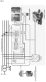
Fig. 4 : Schematic drawing of a rooftop PV system. -
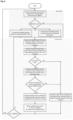
Fig. 5 : Data flow chart for the controller in an APC management system. -
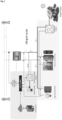
Fig. 6 : Schematic drawing of APC management system in on-grid mode. -
Fig. 7 : Schematic drawing of APC management system in off-grid mode. -
Fig. 8 : Data flow chart for the controller in an APC management system. - The present teaching solves the problem of APC for single/multiple-phase PV system. As explained above, APC occurs when the phase voltages at the POI of PV inverter to the low voltage distribution network hits the network voltage upper limit (such as which is 10% above the nominal voltage of 230 V rms in Belgium i.e. 253 V rms or 1.10 per unit).
- The APC management system disclosed herein will monitor the phase voltages at the POI of PV inverter to the low voltage distribution network and based on actual PV power generation data and the real-time PV inverter injected active power data, the system is configured to determine whether APC occurs and to prevent or reduce such APC by dynamically disconnecting it from the phase(s) that is violating the network voltage upper limit such as 1.10 per unit or 253 V rms and re-connecting it to either of the voltage phases that is within the voltage limits; or household load(s) like battery storage system, heating or refrigerating device(s) to absorb the curtailed PV active power.
- Given the ability to switch to household load(s), wherein such household load(s) are preconditions to using day-ahead PV output power forecast data, the APC system disclosed herein is highly flexible and can even be implemented in single/multiple-phase rooftop PV systems connected through a single/multiple-phase with a low-voltage distribution network. Hence the APC management system is configured to determine whether APC occurs as herein describes and prevents or reduces APC by commanding the secondary relay(s) configured to connect or disconnect the single/multiple-phase rooftop PV system from said household load(s). As further detailed below, in such circumstances the rooftop PV system will be disconnected from the low voltage distribution network and entering an off-grid configuration wherein the PV inverter active power is either directly consumed through the household load(s) and/or stored in an electrical energy storage device such as a battery.
- The APC management system disclosed herein is highly modular in its possibilities of reducing or preventing the APC to occur. Not to be bound to a particular order of events, when the APC management system detects an APC event it will;
- i. Solve the problem of APC for single-phase rooftop PV system dynamically by disconnecting it from the phase that violates the network voltage upper limit and re-connecting it to either of the voltage phases that is within the voltage limits (by controlling S1/S2/S3 relays) to inject the curtailed PV inverter active power into the low voltage distribution network (see
Fig. 4 ). Due to its modular characteristics, the system can be used as a plug and play module; - ii. For the homeowners at the end of the low voltage distribution network, there might be a case when all the phase voltages violate the network voltage upper limit, which means that the PV inverter active power can't be injected into the network by dynamically switching the phase(s) only. Currently, there is no technology at the homeowner level regarding the source of curtailment. To foresee such occurrence, the APC management system predicts the time and duration of APC occurrence by utilizing the day-ahead PV output power forecast data and takes preemptive actions to manage the curtailed PV active power.
In other words, it will prepare available household load(s) like battery storage system to a state capable of storing the curtailed PV inverter active power when it occurs. Such preemptive action could, for example, include decreasing the SOC of battery storage system beforehand in order to save the curtailed PV active power and also managing the household load(s) like adjusting the set temperature of heating and/or refrigeration devices (seeFig. 4 ). Given the implementation of such preemptive actions, the APC management system enables that, in case all the phase voltages violate the network voltage upper limit, which means that the PV inverter active power can't be injected into the network by dynamically switching the phases only, to disconnect the single/multiple-phase PV system from the grid (by controlling S1, S2, S3, S5) and connects it to store the curtailed PV inverter active power in a battery storage system (by controlling S4) (seeFig. 4 ); and - iii. If the low voltage distribution network does not allow to inject the PV inverter active power due to network voltage constraint and battery storage system is either not available or completely charged, the system connects it to other household load(s) like heating or refrigeration devices (by controlling S1, S2, S3, S4 and S5) (see
Fig. 4 ) and could even function in an off-grid configuration as further elaborated below and shown inFigures 6 and7 . - The dataflow to implement an exemplary APC management system according to the present disclosure is provided in
Figure 5 and elaborated as below: - 1) The day-ahead PV output power forecast data is made available in the remote central server from the transmission system operator website like Elia in Belgium (http://www.elia.be/en/grid-data/power-generation/Solar-power-generation-data/Graph) where day-ahead PV output power forecasts and actual PV power generation are uploaded online as per the European regulator guideline. These are adjusted either in the central server or locally in each single/multiple-phase rooftop PV system according to the azimuth, inclination of rooftop, and solar irradiation.
- 2) Based on the adjusted day-ahead PV output power forecasts, the microcontroller takes the following preemptive actions to utilize the curtailed PV active power, if it can't be injected in the low voltage distribution network due to the violation of the network voltage upper limit:
- a. prepares, if available, the battery storage system by decreasing the battery SOC beforehand such that it can be recharged during the period ofAPC;
- b. Prepares household load(s) like heating/refrigeration devices by adjusting the set temperature of heating and/or refrigeration devices beforehand such that it can be utilized further during APC; or
- c. Combinations thereof
- 3) During the runtime, the actual PV power generation data is then acquired in the central server from the transmission system operator website like Elia in Belgium http://www.elia.be/en/grid-data/power-generation/Solar-power-generation-data/Graph and adjusted either in the central server or locally in each single-phase rooftop PV system according to the azimuth, inclination of rooftop, and solar irradiation.
- 4) The microcontroller takes the actual PV power generation data, real-time PV inverter injected active power data and each phase voltage input data as an input. It compares the magnitude of the actual PV power generation data with magnitude of the real-time PV inverter injected active power data and commands the primary and/or secondary relay(s) when the real-time PV inverter injected active power becomes unequal with actual PV panel power generation data where this difference is increasing rapidly with time such that the rate of change of real-time PV inverter injected active power data is for example greater than 100, 200, 300, 400, or 500 W/minute and when the phase voltage violates the network voltage upper limit.
- 5) If the phase voltage violates the network voltage upper limit, and when the real-time PV inverter injected active power data becomes unequal with actual PV power generation data where this difference is increasing with time such that the rate of change of real-time PV inverter injected active power data is greater than 500 W/minute, the microcontroller is activated to ensure that the curtailed PV active power can be utilized in the following order of priority:
- a. Injection into the low voltage distribution network by switching the POI of inverter of single phase PV system between the phases,
- b. locally storage in an energy storage device like a battery by predicting time and duration of APC in advance and preparing the battery beforehand, and/ or
- c. consumed in household load(s) like heating and/or refrigerating device inside homes.
- 6) At the end of the day, steps 1) and 2) are repeated.
- As it is an objective of the present invention to prevent and/or reduce APC events, the system relies on day-ahead PV output power forecast data to prepare household load(s) including battery storage system to act as energy buffers for such APC events. When the phase voltage(s) hits the network voltage upper limit and the difference between the real-time PV inverter injected active power data and the actual PV power generation date changes rapidly, i.e. at a rate of more than 100 W/minute, in particular more than 500W/minute, the system can switch into a full islanded grid/off-grid/nanogrid mode injecting the PV active power into the pre-conditioned battery storage system and household load(s). In such islanded grid/off-grid/nanogrid mode the household network is isolated from the low voltage distribution network by opening the primary relays shown as S1 and S2 in
Figures 6 and7 . In such islanded grid/off-grid/nanogrid mode, the household network will be operating in an islanded mode as a nanogrid requiring the presence of a so named curtailment handling (CH) inverter, a battery storage system and a remote central server. The curtailment handling (CH) inverter is a bidirectional inverter which constitutes the backbone of the system. - The CH inverter is installed behind the meter between the battery storage system and incoming ac phase(s) in a household, as shown in
Fig. 6 andFig. 7 . It is capable of operating during all the possible modes of operation and receives commands from the microcontroller. - The general functioning of the CH inverter in the different modes of operation can be summarized as follows as schematically shown in
Figures 6 and7 ; - During on grid mode (
Fig. 6 ):
The household network is physically connected with the low voltage distribution network by closing S1 and S2. The frequency and voltage of the household network is always governed by the low voltage distribution network parameter. The household load(s) and single/multiple-phase rooftop PV system in the household network must follow the low voltage distribution network voltage and frequency in this mode. During on-grid mode the CH inverter is in slave configuration with respect to the frequency and voltage governed by the low voltage distribution network, and the CH inverter maintains the desired SOC of the battery storage system as requested by the microcontroller, as shown inFig. 8 . Based on the priority set by the microcontroller, the battery storage system is discharged either into household loads(s) or into low voltage distribution network or charged either from the rooftop PV system or low voltage distribution network. - During Off-grid/lslanded/nanogrid mode (
Fig. 7 ):
The household network is isolated from the low voltage distribution network by opening the primary relays S1 and S2. The local CH inverter sets the frequency and voltage at its AC terminals in the off-grid/islanded/nanogrid mode, and accordingly converts the isolated household network into a nanogrid. Since the single/multiple-phase rooftop PV inverter system always operates at unity power factor (zero reactive power), the CH inverter needs to perform the four quadrant operation and provide both active and reactive power to the household load(s). On the one hand if single/multiple-phase rooftop PV inverter system is generating more active power than the load(s) demand, the CH inverter absorbs the excess power through the AC terminals and maintains the nanogrid voltage at the nominal voltage of for example 230 V rms and nominal frequency for example 50 Hz. On the other hand, when the single/multiple-phase rooftop PV inverter system is generating lower than the load(s) demand, and the off-grid/islanded/nanogrid voltage tends to decrease, it supplies the household load(s) using the battery storage system energy and continue to maintain the nominal voltage of 230 V rms (referFig. 8 ). - Thus the APC management system may further comprise a curtailment handling (CH) inverter. In that case, a battery storage system may be included, said battery storage preferably being connected with said CH inverter and optionally under direct operational control of the microcontroller. Therefore, an APC management system as herein described comprises, inter alia:
- A phase voltage input module;
- A microcontroller;
- A Battery storage system;
- A curtailment handling inverter;
- A remote central provider
- A primary relay configured to connect or disconnect the incoming phases of a household network from low voltage distribution network; and
- A secondary relay configured to connect or disconnect the rooftop PV system from household load(s);
- Wherein determining whether APC occurs is still relying on the actual PV power generation data, real-time PV inverter injected active power data and phase voltage(s) input data as extensively described, but further characterized in that the CH inverter sets nominal voltage and frequency at its AC terminals when entering into islanded/off-grid/nanogrid mode.
Claims (14)
- An active power curtailment, APC, management system to prevent or reduce APC in an inverter of a rooftop photovoltaic, PV, system which is connectable to a low voltage distribution network comprising at least one phase, and at least one household load, comprising;- a phase voltage input module configured to measure voltage of the at least one phase and to provide phase voltage input data;- a microcontroller;- at least one primary relay configured to connect or disconnect the rooftop PV system from one or more of said at least one phase; and- at least one secondary relay configured to connect or disconnect the rooftop PV system from one or more of said at least one household load;characterized in that the system comprises communication means to receive online data from a remote provider and in that the microcontroller is configured to determine whether APC occurs based on at least the following inputs:- actual PV power generation data based on the online data received from the remote provider, said actual PV power generation data being a downscale of accumulated real-time actual PV power generation data in accordance with a geographical location of the rooftop PV system,- real-time PV inverter power output data received from the inverter, and- the phase voltage input data received from the phase voltage input module;wherein the microcontroller is further configured to determine whether APC occurs based on the fulfillment of the following conditions:- the phase voltage violates a network voltage upper limit;- there is a difference between the actual PV power generation data and the real-time PV inverter power output data and said difference is increasing with a rate of change greater than a predetermined threshold;and wherein the microcontroller is further configured to prevent or reduce the APC by opening and/or closing of at least one of the primary and/or secondary relays based on said determination.
- The APC management system according to claim 1, wherein the microcontroller is configured to;- use day-ahead PV output power forecast data received from said remote provider to predict occurrence of APC in advance and prepare said at least one household load so that they can act as energy buffers when the rooftop PV system is disconnected from the low voltage distribution network.
- The APC management system according to claim 1 wherein the system is connectable to a multi-phase low voltage distribution network and comprises;a) a phase voltage input module for each phase; andb) a plurality of primary relays configured to connect or disconnect the rooftop PV system to each of said phases.
- The APC management system according to any one of the preceding claims wherein the system comprises a plurality of secondary relays, each configured to connect or disconnect the rooftop PV system from a plurality of household loads.
- The APC management system according to claim 4 wherein the plurality of household loads is selected from a battery storage system, heating and/or cooling devices.
- The APC management system according to claim 1, wherein the microcontroller is further characterized in being configured to use day-ahead PV output power forecast data to predict time and duration of APC in advance and take preemptive action by preparing a battery storage system and/or one or more of the at least one household loads beforehand to absorb the PV inverter output power during the APC in preventing or reducing the APC.
- The APC management system according to any one of the preceding claims wherein the system further comprises a rooftop PV system data module configured to receive technical data of the rooftop PV system such as capacity, azimuth, inclination, and solar irradiation of the rooftop PV system; and wherein the system is configured for adjusting the received actual PV power generation data, and in dependency of claim 2 or claim 6 the day-ahead PV output power forecast data, based on the geographical location and the technical data of the rooftop PV system.
- The APC management system according to any one of the preceding claims wherein the system further comprises the inverter mentioned in claim 1, a battery storage system and a remote central server, wherein the inverter is a curtailment handling, CH, inverter.
- The APC management system according to claim 8, wherein the CH inverter is configured to set a nominal voltage and a nominal frequency at its AC terminals when the rooftop PV system is disconnected from the voltage phases of the low voltage distribution network.
- A method for active power curtailment, APC, management of a rooftop photovoltaic, PV, system comprising a PV inverter connectable to at least one phase of a low voltage distribution network and at least one household load; using a microcontroller connected to at least one primary relay configured to connect or disconnect the rooftop PV system from one or more of said at least one phase and connected to at least one secondary relay configured to connect or disconnect the rooftop PV system from at least one household load(s) in a household network, said method comprisinga) providing phase voltage input data to said microcontroller, said phase voltage input data being provided by a phase voltage input module which measures voltage of the at least one phase;b) providing actual PV power generation data to said microcontroller, said PV power generation data being based on online data received from a remote provider, said actual PV power generation data being a downscale of accumulated real-time actual PV power generation data in accordance with a geographical location of the rooftop PV system; andc) providing real-time PV inverter power output data to said microcontroller, said real-time PV inverter power output data being provided by the PV inverter;wherein said microcontroller determines whether APC occurs based on the fulfillment of the following conditions:- the phase voltage violates a network voltage upper limit;- there is a difference between the actual PV power generation data and the real-time PV inverter power output data and said difference is increasing with a rate of change greater than a predetermined threshold;and wherein the microcontroller opens and/or closes at least one of the primary and/or secondary relays based on said determination so as to prevent or reduce the APC.
- The method according to claim 10, wherein the microcontroller commands the respective primary relay to disconnect from the respective phase and commands at least one of the secondary relays to connect to a battery storage system and/or at least one of the household loads when the phase voltage violates a network voltage upper limit, and the real-time PV inverter power output data becomes unequal with actual PV power generation data.
- The method according to claim 11, wherein the microcontroller further commands a curtailment handling, CH, inverter present between the at least one phase and the battery storage system, to set and maintain a nominal voltage and a nominal frequency at its AC terminals, converting the household network into a islanded grid/off-grid/nano-grid.
- The method according to any one of claims 10 to 12 wherein the actual PV power generation data are adjusted for technical data of the rooftop PV system.
- The method according to claim 10, further comprising providing day-ahead PV output power forecast data to the microcontroller, said forecast data being received from the remote provider, and wherein the microcontroller uses said day-ahead PV output power forecast data to prepare the battery storage system and/or at least one of the household loads in preventing or reducing the APC.
Applications Claiming Priority (1)
| Application Number | Priority Date | Filing Date | Title |
|---|---|---|---|
| EP18248012 | 2018-12-27 |
Publications (3)
| Publication Number | Publication Date |
|---|---|
| EP3675308A1 EP3675308A1 (en) | 2020-07-01 |
| EP3675308C0 EP3675308C0 (en) | 2023-08-30 |
| EP3675308B1 true EP3675308B1 (en) | 2023-08-30 |
Family
ID=65010435
Family Applications (1)
| Application Number | Title | Priority Date | Filing Date |
|---|---|---|---|
| EP19187442.9A Active EP3675308B1 (en) | 2018-12-27 | 2019-07-19 | An active power curtailment management system |
Country Status (1)
| Country | Link |
|---|---|
| EP (1) | EP3675308B1 (en) |
Families Citing this family (2)
| Publication number | Priority date | Publication date | Assignee | Title |
|---|---|---|---|---|
| PL248192B1 (en) * | 2023-12-29 | 2025-11-03 | Politechnika Swietokrzyska | A device that minimizes the downtime of single-phase low-power photovoltaic installation systems. |
| PL248193B1 (en) * | 2023-12-29 | 2025-11-03 | Politechnika Swietokrzyska | A device that minimizes the downtime of 3-phase low-power photovoltaic installation systems. |
Family Cites Families (7)
| Publication number | Priority date | Publication date | Assignee | Title |
|---|---|---|---|---|
| US2652529A (en) | 1952-09-17 | 1953-09-15 | Gen Electric | Phase balancing system |
| US7930070B2 (en) * | 2008-09-25 | 2011-04-19 | Kingston Consulting, Inc. | System, method, and module capable of curtailing energy production within congestive grid operating environments |
| US10424935B2 (en) * | 2009-09-15 | 2019-09-24 | Rajiv Kumar Varma | Multivariable modulator controller for power generation facility |
| DE102009060364B4 (en) | 2009-12-24 | 2023-04-13 | Volkswagen Ag | Device and method for feeding in and/or feeding back electrical energy |
| DE102011078047A1 (en) | 2011-06-24 | 2012-12-27 | Siemens Aktiengesellschaft | Device for controlling the loading of the phases of a three-phase power network |
| CN104333035A (en) | 2014-10-28 | 2015-02-04 | 国网辽宁省电力有限公司朝阳供电公司 | Photovoltaic power distribution system capable of suppressing power grid voltage unbalance |
| WO2017193153A1 (en) * | 2016-05-11 | 2017-11-16 | Commonwealth Scientific And Industrial Research Organisation | Solar power forecasting |
-
2019
- 2019-07-19 EP EP19187442.9A patent/EP3675308B1/en active Active
Also Published As
| Publication number | Publication date |
|---|---|
| EP3675308C0 (en) | 2023-08-30 |
| EP3675308A1 (en) | 2020-07-01 |
Similar Documents
| Publication | Publication Date | Title |
|---|---|---|
| Nour et al. | Review on voltage‐violation mitigation techniques of distribution networks with distributed rooftop PV systems | |
| US10965124B2 (en) | Apparatuses including power electronics circuitry, and related methods of operation | |
| JP6978572B2 (en) | Virtual power plant | |
| CN107425518B (en) | Load management in a hybrid power system | |
| RU2475923C2 (en) | Alternative source energy control | |
| US11749992B2 (en) | Method and system for locally controlling power delivery along a distribution feeder of an electricity grid | |
| US20120229077A1 (en) | Electric power supply system and method for controlling electric power discharge | |
| JP2022525523A (en) | A converter with a power management system for home users to manage power between different loads, including home user electric vehicles | |
| WO2011129054A1 (en) | Electric-power management system, electric-power management method, and section controller | |
| JP6821904B2 (en) | Power system | |
| JP2017521034A (en) | Power grid network gateway aggregation | |
| JP6828567B2 (en) | Grid interconnection system and power system | |
| JP6821905B2 (en) | Power system | |
| JP6921529B2 (en) | Distribution system power flow control method and distribution system | |
| JP2019122150A (en) | Power system and storage battery power conditioner | |
| EP3675308B1 (en) | An active power curtailment management system | |
| Chen et al. | Distributed electric spring based smart thermal loads for overvoltage prevention in LV distributed network using dynamic consensus approach | |
| EP3329576B1 (en) | Uninterruptible power supply and method for managing power flow in a grid-tied photovoltaic system | |
| JP6892191B2 (en) | Power system | |
| Hashemi et al. | Evaluation of voltage regulation mitigation methods due to high penetration of PV generation in residential areas | |
| Lulbadda et al. | Novel concepts for additional functions of smart PV inverters | |
| US20220014025A1 (en) | Feed-in method for a wind power system, and wind power system | |
| EP3920357B1 (en) | System for managing power flow or energy in a nano- or microgrid | |
| US12184070B1 (en) | Controlling local generation capacity independently of the power grid | |
| EP4528966A1 (en) | Method for controlling a microgrid and associated microgrid |
Legal Events
| Date | Code | Title | Description |
|---|---|---|---|
| PUAI | Public reference made under article 153(3) epc to a published international application that has entered the european phase |
Free format text: ORIGINAL CODE: 0009012 |
|
| STAA | Information on the status of an ep patent application or granted ep patent |
Free format text: STATUS: THE APPLICATION HAS BEEN PUBLISHED |
|
| AK | Designated contracting states |
Kind code of ref document: A1 Designated state(s): AL AT BE BG CH CY CZ DE DK EE ES FI FR GB GR HR HU IE IS IT LI LT LU LV MC MK MT NL NO PL PT RO RS SE SI SK SM TR |
|
| AX | Request for extension of the european patent |
Extension state: BA ME |
|
| STAA | Information on the status of an ep patent application or granted ep patent |
Free format text: STATUS: REQUEST FOR EXAMINATION WAS MADE |
|
| 17P | Request for examination filed |
Effective date: 20210108 |
|
| RBV | Designated contracting states (corrected) |
Designated state(s): AL AT BE BG CH CY CZ DE DK EE ES FI FR GB GR HR HU IE IS IT LI LT LU LV MC MK MT NL NO PL PT RO RS SE SI SK SM TR |
|
| STAA | Information on the status of an ep patent application or granted ep patent |
Free format text: STATUS: EXAMINATION IS IN PROGRESS |
|
| 17Q | First examination report despatched |
Effective date: 20211202 |
|
| RIC1 | Information provided on ipc code assigned before grant |
Ipc: H02S 10/20 20140101ALN20220602BHEP Ipc: H02J 3/14 20060101ALN20220602BHEP Ipc: H02J 3/38 20060101AFI20220602BHEP |
|
| GRAP | Despatch of communication of intention to grant a patent |
Free format text: ORIGINAL CODE: EPIDOSNIGR1 |
|
| STAA | Information on the status of an ep patent application or granted ep patent |
Free format text: STATUS: GRANT OF PATENT IS INTENDED |
|
| INTG | Intention to grant announced |
Effective date: 20220728 |
|
| GRAJ | Information related to disapproval of communication of intention to grant by the applicant or resumption of examination proceedings by the epo deleted |
Free format text: ORIGINAL CODE: EPIDOSDIGR1 |
|
| STAA | Information on the status of an ep patent application or granted ep patent |
Free format text: STATUS: EXAMINATION IS IN PROGRESS |
|
| INTC | Intention to grant announced (deleted) | ||
| RIC1 | Information provided on ipc code assigned before grant |
Ipc: H02S 10/20 20140101ALN20230109BHEP Ipc: H02J 3/14 19680901ALN20230109BHEP Ipc: H02J 3/38 19680901AFI20230109BHEP |
|
| GRAP | Despatch of communication of intention to grant a patent |
Free format text: ORIGINAL CODE: EPIDOSNIGR1 |
|
| STAA | Information on the status of an ep patent application or granted ep patent |
Free format text: STATUS: GRANT OF PATENT IS INTENDED |
|
| INTG | Intention to grant announced |
Effective date: 20230313 |
|
| GRAS | Grant fee paid |
Free format text: ORIGINAL CODE: EPIDOSNIGR3 |
|
| GRAA | (expected) grant |
Free format text: ORIGINAL CODE: 0009210 |
|
| STAA | Information on the status of an ep patent application or granted ep patent |
Free format text: STATUS: THE PATENT HAS BEEN GRANTED |
|
| AK | Designated contracting states |
Kind code of ref document: B1 Designated state(s): AL AT BE BG CH CY CZ DE DK EE ES FI FR GB GR HR HU IE IS IT LI LT LU LV MC MK MT NL NO PL PT RO RS SE SI SK SM TR |
|
| REG | Reference to a national code |
Ref country code: GB Ref legal event code: FG4D |
|
| REG | Reference to a national code |
Ref country code: CH Ref legal event code: EP |
|
| REG | Reference to a national code |
Ref country code: DE Ref legal event code: R096 Ref document number: 602019035979 Country of ref document: DE |
|
| REG | Reference to a national code |
Ref country code: IE Ref legal event code: FG4D |
|
| U01 | Request for unitary effect filed |
Effective date: 20230928 |
|
| U07 | Unitary effect registered |
Designated state(s): AT BE BG DE DK EE FI FR IT LT LU LV MT NL PT SE SI Effective date: 20231006 |
|
| PG25 | Lapsed in a contracting state [announced via postgrant information from national office to epo] |
Ref country code: GR Free format text: LAPSE BECAUSE OF FAILURE TO SUBMIT A TRANSLATION OF THE DESCRIPTION OR TO PAY THE FEE WITHIN THE PRESCRIBED TIME-LIMIT Effective date: 20231201 |
|
| PG25 | Lapsed in a contracting state [announced via postgrant information from national office to epo] |
Ref country code: IS Free format text: LAPSE BECAUSE OF FAILURE TO SUBMIT A TRANSLATION OF THE DESCRIPTION OR TO PAY THE FEE WITHIN THE PRESCRIBED TIME-LIMIT Effective date: 20231230 |
|
| PG25 | Lapsed in a contracting state [announced via postgrant information from national office to epo] |
Ref country code: RS Free format text: LAPSE BECAUSE OF FAILURE TO SUBMIT A TRANSLATION OF THE DESCRIPTION OR TO PAY THE FEE WITHIN THE PRESCRIBED TIME-LIMIT Effective date: 20230830 Ref country code: NO Free format text: LAPSE BECAUSE OF FAILURE TO SUBMIT A TRANSLATION OF THE DESCRIPTION OR TO PAY THE FEE WITHIN THE PRESCRIBED TIME-LIMIT Effective date: 20231130 Ref country code: IS Free format text: LAPSE BECAUSE OF FAILURE TO SUBMIT A TRANSLATION OF THE DESCRIPTION OR TO PAY THE FEE WITHIN THE PRESCRIBED TIME-LIMIT Effective date: 20231230 Ref country code: HR Free format text: LAPSE BECAUSE OF FAILURE TO SUBMIT A TRANSLATION OF THE DESCRIPTION OR TO PAY THE FEE WITHIN THE PRESCRIBED TIME-LIMIT Effective date: 20230830 Ref country code: GR Free format text: LAPSE BECAUSE OF FAILURE TO SUBMIT A TRANSLATION OF THE DESCRIPTION OR TO PAY THE FEE WITHIN THE PRESCRIBED TIME-LIMIT Effective date: 20231201 |
|
| PG25 | Lapsed in a contracting state [announced via postgrant information from national office to epo] |
Ref country code: PL Free format text: LAPSE BECAUSE OF FAILURE TO SUBMIT A TRANSLATION OF THE DESCRIPTION OR TO PAY THE FEE WITHIN THE PRESCRIBED TIME-LIMIT Effective date: 20230830 |
|
| PG25 | Lapsed in a contracting state [announced via postgrant information from national office to epo] |
Ref country code: ES Free format text: LAPSE BECAUSE OF FAILURE TO SUBMIT A TRANSLATION OF THE DESCRIPTION OR TO PAY THE FEE WITHIN THE PRESCRIBED TIME-LIMIT Effective date: 20230830 |
|
| PG25 | Lapsed in a contracting state [announced via postgrant information from national office to epo] |
Ref country code: SM Free format text: LAPSE BECAUSE OF FAILURE TO SUBMIT A TRANSLATION OF THE DESCRIPTION OR TO PAY THE FEE WITHIN THE PRESCRIBED TIME-LIMIT Effective date: 20230830 Ref country code: RO Free format text: LAPSE BECAUSE OF FAILURE TO SUBMIT A TRANSLATION OF THE DESCRIPTION OR TO PAY THE FEE WITHIN THE PRESCRIBED TIME-LIMIT Effective date: 20230830 Ref country code: ES Free format text: LAPSE BECAUSE OF FAILURE TO SUBMIT A TRANSLATION OF THE DESCRIPTION OR TO PAY THE FEE WITHIN THE PRESCRIBED TIME-LIMIT Effective date: 20230830 Ref country code: CZ Free format text: LAPSE BECAUSE OF FAILURE TO SUBMIT A TRANSLATION OF THE DESCRIPTION OR TO PAY THE FEE WITHIN THE PRESCRIBED TIME-LIMIT Effective date: 20230830 Ref country code: SK Free format text: LAPSE BECAUSE OF FAILURE TO SUBMIT A TRANSLATION OF THE DESCRIPTION OR TO PAY THE FEE WITHIN THE PRESCRIBED TIME-LIMIT Effective date: 20230830 |
|
| REG | Reference to a national code |
Ref country code: DE Ref legal event code: R097 Ref document number: 602019035979 Country of ref document: DE |
|
| PLBE | No opposition filed within time limit |
Free format text: ORIGINAL CODE: 0009261 |
|
| STAA | Information on the status of an ep patent application or granted ep patent |
Free format text: STATUS: NO OPPOSITION FILED WITHIN TIME LIMIT |
|
| U20 | Renewal fee for the european patent with unitary effect paid |
Year of fee payment: 6 Effective date: 20240619 |
|
| 26N | No opposition filed |
Effective date: 20240603 |
|
| PG25 | Lapsed in a contracting state [announced via postgrant information from national office to epo] |
Ref country code: MC Free format text: LAPSE BECAUSE OF FAILURE TO SUBMIT A TRANSLATION OF THE DESCRIPTION OR TO PAY THE FEE WITHIN THE PRESCRIBED TIME-LIMIT Effective date: 20230830 |
|
| PGFP | Annual fee paid to national office [announced via postgrant information from national office to epo] |
Ref country code: GB Payment date: 20250619 Year of fee payment: 7 |
|
| PG25 | Lapsed in a contracting state [announced via postgrant information from national office to epo] |
Ref country code: IE Free format text: LAPSE BECAUSE OF NON-PAYMENT OF DUE FEES Effective date: 20240719 |
|
| U20 | Renewal fee for the european patent with unitary effect paid |
Year of fee payment: 7 Effective date: 20250620 |
|
| PGFP | Annual fee paid to national office [announced via postgrant information from national office to epo] |
Ref country code: CH Payment date: 20250801 Year of fee payment: 7 |
|
| PG25 | Lapsed in a contracting state [announced via postgrant information from national office to epo] |
Ref country code: CY Free format text: LAPSE BECAUSE OF FAILURE TO SUBMIT A TRANSLATION OF THE DESCRIPTION OR TO PAY THE FEE WITHIN THE PRESCRIBED TIME-LIMIT; INVALID AB INITIO Effective date: 20190719 |
|
| PG25 | Lapsed in a contracting state [announced via postgrant information from national office to epo] |
Ref country code: HU Free format text: LAPSE BECAUSE OF FAILURE TO SUBMIT A TRANSLATION OF THE DESCRIPTION OR TO PAY THE FEE WITHIN THE PRESCRIBED TIME-LIMIT; INVALID AB INITIO Effective date: 20190719 |