EP3675272B1 - Secondary battery static pressure jig and method for adjusting internal pressure of secondary battery by using same - Google Patents
Secondary battery static pressure jig and method for adjusting internal pressure of secondary battery by using same Download PDFInfo
- Publication number
- EP3675272B1 EP3675272B1 EP19793050.6A EP19793050A EP3675272B1 EP 3675272 B1 EP3675272 B1 EP 3675272B1 EP 19793050 A EP19793050 A EP 19793050A EP 3675272 B1 EP3675272 B1 EP 3675272B1
- Authority
- EP
- European Patent Office
- Prior art keywords
- piezoelectric element
- pressure
- voltage signal
- battery cell
- secondary battery
- Prior art date
- Legal status (The legal status is an assumption and is not a legal conclusion. Google has not performed a legal analysis and makes no representation as to the accuracy of the status listed.)
- Active
Links
Images




Classifications
-
- G—PHYSICS
- G01—MEASURING; TESTING
- G01L—MEASURING FORCE, STRESS, TORQUE, WORK, MECHANICAL POWER, MECHANICAL EFFICIENCY, OR FLUID PRESSURE
- G01L1/00—Measuring force or stress, in general
- G01L1/16—Measuring force or stress, in general using properties of piezoelectric devices
-
- H—ELECTRICITY
- H01—ELECTRIC ELEMENTS
- H01M—PROCESSES OR MEANS, e.g. BATTERIES, FOR THE DIRECT CONVERSION OF CHEMICAL ENERGY INTO ELECTRICAL ENERGY
- H01M10/00—Secondary cells; Manufacture thereof
- H01M10/42—Methods or arrangements for servicing or maintenance of secondary cells or secondary half-cells
- H01M10/4285—Testing apparatus
-
- H—ELECTRICITY
- H01—ELECTRIC ELEMENTS
- H01M—PROCESSES OR MEANS, e.g. BATTERIES, FOR THE DIRECT CONVERSION OF CHEMICAL ENERGY INTO ELECTRICAL ENERGY
- H01M10/00—Secondary cells; Manufacture thereof
- H01M10/42—Methods or arrangements for servicing or maintenance of secondary cells or secondary half-cells
-
- G—PHYSICS
- G01—MEASURING; TESTING
- G01R—MEASURING ELECTRIC VARIABLES; MEASURING MAGNETIC VARIABLES
- G01R31/00—Arrangements for testing electric properties; Arrangements for locating electric faults; Arrangements for electrical testing characterised by what is being tested not provided for elsewhere
- G01R31/36—Arrangements for testing, measuring or monitoring the electrical condition of accumulators or electric batteries, e.g. capacity or state of charge [SoC]
- G01R31/396—Acquisition or processing of data for testing or for monitoring individual cells or groups of cells within a battery
-
- H—ELECTRICITY
- H01—ELECTRIC ELEMENTS
- H01M—PROCESSES OR MEANS, e.g. BATTERIES, FOR THE DIRECT CONVERSION OF CHEMICAL ENERGY INTO ELECTRICAL ENERGY
- H01M10/00—Secondary cells; Manufacture thereof
- H01M10/42—Methods or arrangements for servicing or maintenance of secondary cells or secondary half-cells
- H01M10/48—Accumulators combined with arrangements for measuring, testing or indicating the condition of cells, e.g. the level or density of the electrolyte
-
- Y—GENERAL TAGGING OF NEW TECHNOLOGICAL DEVELOPMENTS; GENERAL TAGGING OF CROSS-SECTIONAL TECHNOLOGIES SPANNING OVER SEVERAL SECTIONS OF THE IPC; TECHNICAL SUBJECTS COVERED BY FORMER USPC CROSS-REFERENCE ART COLLECTIONS [XRACs] AND DIGESTS
- Y02—TECHNOLOGIES OR APPLICATIONS FOR MITIGATION OR ADAPTATION AGAINST CLIMATE CHANGE
- Y02E—REDUCTION OF GREENHOUSE GAS [GHG] EMISSIONS, RELATED TO ENERGY GENERATION, TRANSMISSION OR DISTRIBUTION
- Y02E60/00—Enabling technologies; Technologies with a potential or indirect contribution to GHG emissions mitigation
- Y02E60/10—Energy storage using batteries
Definitions
- the present invention relates to a secondary battery static pressure jig and a secondary cell internal pressure control method using the same, and more particularly, to a secondary battery static pressure jig using a piezoelectric element and a secondary battery internal pressure control method using the same.
- the secondary battery examples include a nickel-cadmium battery, a nickel-hydrogen battery, a nickel-zinc battery, a lithium secondary battery, and the like, and the secondary battery may be manufactured through a process of assembling a cell and a process of activating a cell.
- the cell activating process stabilizes a battery structure through processes of charging, aging, and discharging of the assembled battery, and makes the battery structure usable.
- the cell is mounted on a predetermined pressing jig for smooth current conduction, and then processes such as charging and discharging are performed under conditions necessary for battery activation.
- the pressing jig is used for testing performance of the manufactured secondary battery in advance, and also prevents an increase in a thickness of the battery cell, thereby reducing adverse effects on battery cell performance.
- US 2012 189 879 A1 relates to a method and device for application of a pressure to a battery, which has at least one or more cells.
- the device is designed to carry out the method such that the pressure is adjusted as a function of the respective battery volume and/or of the respective battery state of charge.
- Embodiments of the present invention have been proposed in order to solve the above-mentioned problems of the previously proposed methods, and the objects thereof are to measure a pressure with a piezoelectric element, which measures the pressure, included in a jig used in charging and discharging tests of a secondary battery, and to maintain a pressure inside the secondary battery at a constant pressure by controlling a volume of the piezoelectric element in accordance with the measured pressure and using a volume change of the piezoelectric element.
- An embodiment of the present invention provides a secondary battery static pressure jig as defined in claim 1, the secondary battery static pressure jig including: a supporting member disposed on both surfaces of a battery cell to support the battery cell; a piezoelectric element that is disposed on at least one of surfaces of the supporting member and the battery cell contacting each other and measures a pressure applied to the battery cell; and a controlling part that controls a volume of the piezoelectric element according to the pressure measured by the piezoelectric element, wherein a volume of the piezoelectric element may be changed according to the volume change of the battery cell, and the pressure applied to the battery cell from the supporting member by the volume change of the piezoelectric element may be made to be a constant pressure.
- the controlling part includes: a converting part that converts a pressure value measured by the piezoelectric element into a first voltage signal; a calculating part that calculates a second voltage signal for changing the battery cell to an initial pressure state using the first voltage signal; and a driving part that drives the piezoelectric element according to the second voltage signal.
- the supporting member includes a first supporting part contacting an upper surface of the battery cell; and a second supporting part contacting a lower surface of the battery cell.
- the secondary battery static pressure jig further includes a coupling part that penetrates the supporting member and couples the first supporting part and the second supporting part to each other, wherein the coupling part is movably coupled according to a change in the pressure applied to the battery cell according to a change in the volume of the piezoelectric element.
- the calculating part may derive a difference between a first pressure value corresponding to the first voltage signal and a second pressure value that is an initial pressure of the battery cell, and may calculate the second voltage signal corresponding to a difference between the first pressure value and the second pressure value.
- the driving part may control the pressure applied to the battery cell by transmitting the second voltage signal to the piezoelectric element and driving the piezoelectric element according to the second voltage signal to change a volume of the piezoelectric element.
- the piezoelectric element may be cylindrical.
- the number of piezoelectric elements may be plural.
- the controlling part may receive the first voltage signal that the pressure measured by the piezoelectric element is converted through a first signal line, and the piezoelectric element may receive the second voltage signal calculated by the controlling part through the second signal line.
- a negative electrode included in the battery cell may be made of lithium metal.
- Another embodiment of the present invention provides an internal pressure control method of a secondary battery, including: disposing a battery cell in a supporting member to support the battery cell; measuring, by a piezoelectric element disposed on at least one of surfaces of the supporting member and the battery contacting each other, a pressure applied to the battery cell; controlling a volume of the piezoelectric element according to the pressure measured by the piezoelectric element, and moving a coupling part according to a change in the pressure applied to the battery cell according to a change in the volume of the piezoelectric element.
- the controlling of the volume of the piezoelectric element includes: converting the pressure value measured by the piezoelectric element into a first voltage signal; calculating a second voltage signal for changing the battery cell to an initial pressure state using the first voltage signal; and driving the piezoelectric element according to the second voltage signal.
- the calculating of the second voltage signal may include: converting the first voltage signal to a first digital signal; converting the first digital signal into a second digital signal for changing the battery cell into an initial pressure state by converting the first digital signal; converting the second digital signal to a second analog signal; and amplifying the second analog signal to convert the second analog signal into the second voltage signal.
- the calculating of the second voltage signal may include deriving a difference between a first pressure value corresponding to the first voltage signal and a second pressure value that is an initial pressure of the battery cell, and calculating the second voltage signal corresponding to a difference between the first pressure value and the second pressure value.
- the driving of the piezoelectric element may include controlling the pressure applied to the battery cell by transmitting the second voltage signal to the piezoelectric element, and driving the piezoelectric element according to the second voltage signal to change a volume of the piezoelectric element.
- the secondary battery static pressure jig proposed in the present invention and the secondary battery internal pressure control method using the same, it is possible to measure a pressure with a piezoelectric element included in a jig used in charging and discharging tests of a secondary battery, and it is possible to maintain a pressure inside the secondary battery at a constant pressure by changing a volume of the piezoelectric element in accordance with the measured pressure.
- the phrase “in a plan view” means viewing a target portion from the top
- the phrase “in a cross-sectional view” means viewing a cross-section formed by vertically cutting a target portion from the side.
- the lithium secondary battery which is rechargeable and may have a small size and a large capacity, has been widely used in various fields due to a high power capacity and a long lifespan.
- the negative electrode of 50 um (20 um/10 um/20 um) is increased to 90 um per bicell.
- the battery cell is pressurized by using a jig when the lithium battery is charged, a thickness change of the cell is further increased.
- FIG. 1 illustrates a change in thickness of a lithium battery according to whether or not a pressure is applied when the battery is charged.
- FIG. 1 (a) shows a case in which no pressure is applied
- FIG. 1 (b) shows a case in which a press is applied using a jig.
- a battery cell according to an embodiment of the present invention may include a negative electrode made of lithium metal, and in order to solve the above-described problem, hereinafter, a positive pressure jig for allowing the pressure applied to the battery to be charged and discharged to be a positive pressure will be described.
- a positive pressure jig for allowing the pressure applied to the battery to be charged and discharged to be a positive pressure.
- the positive pressure jig according to the embodiment of the present invention and the internal pressure control method of the secondary battery using the positive pressure jig may be applied not only to a battery cell including a negative electrode made of only lithium metal but also to a negative electrode made of graphite.
- FIG. 2 illustrates a schematic view of a secondary battery static pressure jig according to an embodiment of the present invention.
- a secondary battery static pressure jig 10 includes a supporting member 200 disposed to a battery cell 100 to support the battery cell 100, a piezoelectric element 300 for measuring pressure, and a controlling part 400 for controlling a volume of the piezoelectric element 300.
- the supporting member 200 is disposed to be in contact with respective surfaces of the battery cell 100 to support the battery cell 100.
- the supporting member 200 may include a first supporting part 210 contacting an upper surface of the battery cell 100, and a second supporting part 220 contacting a lower surface of the battery cell 100.
- the piezoelectric element 300 serves to measure the pressure applied to the battery cell 100. Specifically, the pressure applied to the battery cell 100 by the supporting member 200 is measured.
- the piezoelectric element is one in which a material having a specific polarization property with a specific material is filled between both electrode plates, and means an element in which a voltage is generated from both electrode plates due to a polarization change of the internal material when a pressure is applied to the specific material.
- the phenomenon in which the voltage is generated by the pressure is called a piezoelectric effect, and the pressure may be measured using an electrical signal thus generated.
- the piezoelectric element 300 measures the applied pressure and changes it to a voltage signal, and transmits the changed voltage signal to a user so that the user may check the measured pressure value.
- the piezoelectric element 300 may serve not only to measure the pressure but also to control the pressure by pressing through a volume change of the piezoelectric element 300 itself. That is, the pressure may be controlled while measuring the pressure using the piezoelectric element 300.
- a phenomenon in which a voltage signal (electrical signal) is applied to deform (mechanically change) a material is called an inverse piezoelectric effect, and in the present invention, it is possible to control the volume of the piezoelectric element 300 by using the inverse piezoelectric effect.
- the present invention utilizes effects that the shape and volume of the piezoelectric element 300 are changed by adding a voltage line to the piezoelectric element 300 and inversely transmitting a voltage to the piezoelectric element 300.
- a specific operational flow of measuring and controlling the pressure using the piezoelectric element 300 will be described with reference to FIG. 4 and FIG. 5 below.
- the controlling part 400 serves to control the volume of the piezoelectric element 300 according to the pressure measured by the piezoelectric element 300.
- the piezoelectric element 300 of the present invention utilizes both the piezoelectric effect and the inverse piezoelectric effect. That is, the volume of the piezoelectric element 300 according to the present invention is changed, the pressure value measured by the piezoelectric element 300 is changed according to the volume change of the battery cell 100 generated when the battery is charged or discharged, and the volume of the piezoelectric element 300 is changed according to the measured pressure value.
- the present invention is characterized in that the pressure applied to the battery cell 100 from the supporting member 200 through the volume change of the piezoelectric element 300 becomes a positive pressure.
- the positive pressure means that the pressure applied to the battery cell is maintained constant.
- FIG. 3 illustrates a schematic view of a secondary battery static pressure jig according to an embodiment of the present invention.
- the supporting member 200 that has a larger area than the battery cell 100 and supports the battery cell 100, and a piezoelectric element 300 that is disposed between the battery cell 100 and the supporting member 200 and is disposed on at least one of surfaces of the battery cell 100 and the supporting member 200 contacting each other, may be included.
- the piezoelectric element 300 may be a cylindrical piezoelectric element 300, and a plurality of piezoelectric elements 300 may be disposed. For example, as shown in FIG. 3 , nine piezoelectric elements 300 may be disposed to the battery cell 100.
- the number of piezoelectric elements 300 is not limited, but preferably, about four to nine piezoelectric elements 300 may be disposed.
- the piezoelectric element 300 in the present invention is not limited to the cylindrical piezoelectric element, but may be a plate-shaped piezoelectric element.
- the piezoelectric element 300 generates and outputs a voltage signal according to the pressure applied by the volume change of the battery cell 100 during charging and discharging of the battery, and the controlling part 400 that receives the voltage signal transmits a voltage required to reach a constant pressure value to the piezoelectric element 300, and thus it is possible to control the volume of any of the piezoelectric elements 300.
- the supporting member 200 described above is disposed on the upper and lower surfaces of the battery cell 100 to support the battery cell 100, and it serves to fix the battery cell 100 so as to prevent the battery cell 100 from moving when the pressure of the battery cell 100 is measured.
- a coupling part 500 that passes through the supporting member 200 and connects the first supporting part 210 and the second supporting part 220 in FIG. 2 may be provided in respective corners of the supporting members 200.
- the coupling part 500 may be a fixed type using a bolt, but the present invention is not limited thereto, and any of coupling parts 500 that may be movably connected to the piezoelectric element 300 in accordance with a change in pressure applied to the battery cell 100 in accordance with the volume change of the piezoelectric element 300 are possible.
- a tension spring may be inserted into the coupling part 500, and in this case, when the volume of the battery cell 100 is reduced, it may have a restoring force to return to an original thickness.
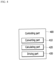
- FIG. 4 illustrates a schematic view of a controlling part of a secondary battery static pressure jig according to an embodiment of the present invention.
- the controlling part 400 which controls the volume of the piezoelectric element 300, may include, as shown in FIG. 4 , a converting part 410, a calculating part 420, and a driving part 430.
- the converting part 410 converts the pressure value measured by the piezoelectric element 300 into a first voltage signal
- the calculating part 420 calculates a second voltage signal required to change the battery cell 100 into an initial pressure state using the first voltage signal converted by the converting part 410.
- the calculating part 420 derives a difference between a first pressure value, which is a pressure value corresponding to the first voltage signal converted by the converting part 410, and a second pressure value, which is an initial pressure value of the battery cell 100, and then calculates the second voltage signal corresponding to the difference between the first pressure value and the second pressure value.
- the initial pressure value may be 0 V, but it is not limited thereto, and it may mean a pressure value initially set by a user.
- the driving part 430 drives the piezoelectric element 300 according to the second voltage signal calculated by the calculating part 420. That is, in order to finally control the pressure applied to the battery cell 100, it transmits the second voltage signal calculated by the calculating part 420 to the piezoelectric element 300 so that the piezoelectric element 300 is driven according to the transmitted second voltage signal, and changes the volume of the piezoelectric element 300.
- FIG. 5 illustrates an operational flow of a controlling part of a secondary battery static pressure jig according to an embodiment of the present invention.
- FIG. 5 is a diagram illustrating a signal transmission process in the controlling part 400, and as shown in FIG. 5 , when a pressure is applied, the piezoelectric element 300 measures the pressure and changes the measured pressure to a voltage signal.
- the changed voltage signal is converted into a digital signal that is easy to process through a first signal analog to digital converter (ADC) of FIG. 5 , and a PID feedback circuit receives the converted signal and calculates a difference between the converted signal and the initial pressure value so as to calculate a value for returning to the initial pressure state.
- ADC first signal analog to digital converter
- a second signal digital to analog converter converts the value calculated by the PID feedback circuit into an analog signal, which is a signal for transmitting the converted value to the piezoelectric element 300, and a signal amplifier amplifies the analog signal to a voltage for driving the piezoelectric element 300. That is, the controlling part 400 receives the first voltage signal of which the pressure measured by the piezoelectric element 300 is converted through a first signal line, and the piezoelectric element 300 receives the second voltage signal calculated by the controlling part 400 through a second signal line.
- DAC digital to analog converter
- the driving part 430 drives the piezoelectric element 300 with the amplified voltage, thereby increasing or decreasing the volume of the piezoelectric element 300 to maintain the inside of the secondary battery at a constant pressure.
- FIG. 6 illustrates a flowchart of a secondary cell internal pressure control method using a secondary cell according to an embodiment of the present invention.
- the internal pressure control method of the secondary battery includes: disposing a battery cell in a supporting member to support the battery cell (S100); measuring, by a piezoelectric element disposed on at least one of surfaces of the supporting member and the battery contacting each other, a pressure applied to the battery cell (S200), and controlling a volume of the piezoelectric element according to the pressure measured by the piezoelectric element (S300).
- Step S300 of controlling the volume of the piezoelectric element may include converting the pressure value measured by the piezoelectric element into a first voltage signal (S310), calculating a second voltage signal for changing the battery cell to an initial pressure state using the first voltage signal (S320), and driving the piezoelectric element according to the second voltage signal (S330).
- step S320 of calculating the second voltage signal a difference between a first pressure value corresponding to the first voltage signal and a second pressure value that is an initial pressure of the battery cell, may be derived, and the second voltage signal corresponding to a difference between the first pressure value and the second pressure value may be calculated.
- step S330 of driving the piezoelectric element it is possible to control the pressure applied to the battery cell by transmitting the second voltage signal to the piezoelectric element and driving the piezoelectric element according to the second voltage signal to change the volume of the piezoelectric element.
- Detailed contents related to the respective steps have been described in relation to the secondary battery static pressure jig 10 according to the embodiment of the present invention, and a detailed description thereof is thus omitted.
Landscapes
- Physics & Mathematics (AREA)
- General Physics & Mathematics (AREA)
- Engineering & Computer Science (AREA)
- Manufacturing & Machinery (AREA)
- Chemical & Material Sciences (AREA)
- Chemical Kinetics & Catalysis (AREA)
- Electrochemistry (AREA)
- General Chemical & Material Sciences (AREA)
- Secondary Cells (AREA)
Description
- The present invention relates to a secondary battery static pressure jig and a secondary cell internal pressure control method using the same, and more particularly, to a secondary battery static pressure jig using a piezoelectric element and a secondary battery internal pressure control method using the same.
- In modern society, in accordance with the daily use of portable devices such as a mobile phone, a laptop computer, a camcorder, a digital camera, and the like, technologies of a field related to the portable devices have been actively developed, and the necessity to develop a secondary battery used for the portable devices has increased.
- Examples of the secondary battery include a nickel-cadmium battery, a nickel-hydrogen battery, a nickel-zinc battery, a lithium secondary battery, and the like, and the secondary battery may be manufactured through a process of assembling a cell and a process of activating a cell. The cell activating process stabilizes a battery structure through processes of charging, aging, and discharging of the assembled battery, and makes the battery structure usable. Specifically, in the cell activating process, the cell is mounted on a predetermined pressing jig for smooth current conduction, and then processes such as charging and discharging are performed under conditions necessary for battery activation. The pressing jig is used for testing performance of the manufactured secondary battery in advance, and also prevents an increase in a thickness of the battery cell, thereby reducing adverse effects on battery cell performance.
- However, in the case in which the pressure jig is used in the process step, when the pressure jig is pressed at a constant force without considering a change in the thickness of the battery cell due to internal expansion of the battery cell or the like, an excessive strong pressure is applied in accordance with the internal expansion of the battery cell, thereby causing problems. In order to solve such a problem, it is necessary to maintain the pressure applied to the cell to be charged and discharged to be constant.
-
US 2012 189 879 A1 relates to a method and device for application of a pressure to a battery, which has at least one or more cells. The device is designed to carry out the method such that the pressure is adjusted as a function of the respective battery volume and/or of the respective battery state of charge. - Embodiments of the present invention have been proposed in order to solve the above-mentioned problems of the previously proposed methods, and the objects thereof are to measure a pressure with a piezoelectric element, which measures the pressure, included in a jig used in charging and discharging tests of a secondary battery, and to maintain a pressure inside the secondary battery at a constant pressure by controlling a volume of the piezoelectric element in accordance with the measured pressure and using a volume change of the piezoelectric element.
- An embodiment of the present invention provides a secondary battery static pressure jig as defined in claim 1, the secondary battery static pressure jig including: a supporting member disposed on both surfaces of a battery cell to support the battery cell; a piezoelectric element that is disposed on at least one of surfaces of the supporting member and the battery cell contacting each other and measures a pressure applied to the battery cell; and a controlling part that controls a volume of the piezoelectric element according to the pressure measured by the piezoelectric element, wherein a volume of the piezoelectric element may be changed according to the volume change of the battery cell, and the pressure applied to the battery cell from the supporting member by the volume change of the piezoelectric element may be made to be a constant pressure.
- The controlling part includes: a converting part that converts a pressure value measured by the piezoelectric element into a first voltage signal; a calculating part that calculates a second voltage signal for changing the battery cell to an initial pressure state using the first voltage signal; and a driving part that drives the piezoelectric element according to the second voltage signal.
- The supporting member includes a first supporting part contacting an upper surface of the battery cell; and a second supporting part contacting a lower surface of the battery cell.
- The secondary battery static pressure jig further includes a coupling part that penetrates the supporting member and couples the first supporting part and the second supporting part to each other, wherein the coupling part is movably coupled according to a change in the pressure applied to the battery cell according to a change in the volume of the piezoelectric element.
- The calculating part may derive a difference between a first pressure value corresponding to the first voltage signal and a second pressure value that is an initial pressure of the battery cell, and may calculate the second voltage signal corresponding to a difference between the first pressure value and the second pressure value.
- The driving part may control the pressure applied to the battery cell by transmitting the second voltage signal to the piezoelectric element and driving the piezoelectric element according to the second voltage signal to change a volume of the piezoelectric element.
- The piezoelectric element may be cylindrical.
- The number of piezoelectric elements may be plural.
- The controlling part may receive the first voltage signal that the pressure measured by the piezoelectric element is converted through a first signal line, and the piezoelectric element may receive the second voltage signal calculated by the controlling part through the second signal line.
- A negative electrode included in the battery cell may be made of lithium metal.
- Another embodiment of the present invention provides an internal pressure control method of a secondary battery, including: disposing a battery cell in a supporting member to support the battery cell; measuring, by a piezoelectric element disposed on at least one of surfaces of the supporting member and the battery contacting each other, a pressure applied to the battery cell; controlling a volume of the piezoelectric element according to the pressure measured by the piezoelectric element, and moving a coupling part according to a change in the pressure applied to the battery cell according to a change in the volume of the piezoelectric element.
- The controlling of the volume of the piezoelectric element includes: converting the pressure value measured by the piezoelectric element into a first voltage signal; calculating a second voltage signal for changing the battery cell to an initial pressure state using the first voltage signal; and driving the piezoelectric element according to the second voltage signal.
- The calculating of the second voltage signal may include: converting the first voltage signal to a first digital signal; converting the first digital signal into a second digital signal for changing the battery cell into an initial pressure state by converting the first digital signal; converting the second digital signal to a second analog signal; and amplifying the second analog signal to convert the second analog signal into the second voltage signal.
- The calculating of the second voltage signal may include deriving a difference between a first pressure value corresponding to the first voltage signal and a second pressure value that is an initial pressure of the battery cell, and calculating the second voltage signal corresponding to a difference between the first pressure value and the second pressure value.
- The driving of the piezoelectric element may include controlling the pressure applied to the battery cell by transmitting the second voltage signal to the piezoelectric element, and driving the piezoelectric element according to the second voltage signal to change a volume of the piezoelectric element.
- According to the secondary battery static pressure jig proposed in the present invention and the secondary battery internal pressure control method using the same, it is possible to measure a pressure with a piezoelectric element included in a jig used in charging and discharging tests of a secondary battery, and it is possible to maintain a pressure inside the secondary battery at a constant pressure by changing a volume of the piezoelectric element in accordance with the measured pressure.
-
-
FIG. 1 illustrates a change in thickness of a lithium battery according to whether or not a pressure is applied when the battery is charged. -
FIG. 2 illustrates a schematic view of a secondary battery static pressure jig according to an embodiment of the present invention. -
FIG. 3 illustrates a schematic view of a secondary battery static pressure jig according to an embodiment of the present invention. -
FIG. 4 illustrates a schematic view of a controlling part of a secondary battery static pressure jig according to an embodiment of the present invention. -
FIG. 5 illustrates an operational flow of a controlling part of a secondary battery static pressure jig according to an embodiment of the present invention. -
FIG. 6 illustrates a flowchart of a secondary cell internal pressure control method using a secondary cell according to an embodiment of the present invention. - The present invention will be described more fully hereinafter with reference to the accompanying drawings, in which exemplary embodiments of the invention are shown. As those skilled in the art would realize, the described embodiments may be modified in various different ways, within the scope of the appended claims.
- Parts that are irrelevant to the description will be omitted to clearly describe the present disclosure, and like reference numerals designate like elements throughout the specification.
- Further, in the drawings, the size and thickness of each element are arbitrarily illustrated for ease of description, and the present disclosure is not necessarily limited to those illustrated in the drawings. In the drawings, the thicknesses of layers, films, panels, regions, etc., are exaggerated for clarity. In the drawings, for ease of description, the thicknesses of some layers and areas are exaggerated.
- It will be understood that when an element such as a layer, film, region, or substrate is referred to as being "on" another element, it can be directly on the other element or intervening elements may also be present. In contrast, when an element is referred to as being "directly on" another element, there are no intervening elements present. Further, in the specification, the word "on" or "above" means positioned on or below the object portion, and does not necessarily mean positioned on the upper side of the object portion based on a gravitational direction.
- In addition, throughout the specification, unless explicitly described to the contrary, the word "comprise" and variations such as "comprises" or "comprising" will be understood to imply the inclusion of stated elements but not the exclusion of any other elements.
- Further, throughout the specification, the phrase "in a plan view" means viewing a target portion from the top, and the phrase "in a cross-sectional view" means viewing a cross-section formed by vertically cutting a target portion from the side.
- Among secondary batteries, particularly, the lithium secondary battery, which is rechargeable and may have a small size and a large capacity, has been widely used in various fields due to a high power capacity and a long lifespan.
- However, when a pure lithium metal is used as a negative electrode in a lithium secondary battery, since its charging mechanism differs from a typical graphite negative electrode, the thickness expansion of the negative electrode leads to to the expansion of the cell, thereby causing a serious problem. In the graphite negative electrode, lithium moved from the positive electrode is intercalated into graphite, which has a layered structure, but it is directly stacked on the lithium metal cathode to increase its thickness. For example, when positive electrode loading of about 4.0 mAh/cm2 is applied, a thickness increase of 20 um occurs. That is, when a 10 um Cu current collector is used with a 20 um lithium negative electrode based on both sides using the positive electrode above, the negative electrode of 50 um (20 um/10 um/20 um) is increased to 90 um per bicell. Considering growth characteristics of the lithium negative electrode, unless the battery cell is pressurized by using a jig when the lithium battery is charged, a thickness change of the cell is further increased.
-
FIG. 1 illustrates a change in thickness of a lithium battery according to whether or not a pressure is applied when the battery is charged. -
FIG. 1 (a) shows a case in which no pressure is applied, andFIG. 1 (b) shows a case in which a press is applied using a jig. Referring toFIG. 1 (a) and FIG. 1 (b) , it can be seen that the thickness change of the battery increases depending on whether or not the pressure is applied when the lithium battery is charged, and thus, it is possible to confirm necessity to pressurize the battery when the battery is charged or discharged. However, in a case of a conventional pressurizing jig which is pressed with constant force without considering a thickness state of lithium due to lithium expansion or the like, excessive pressure may be applied depending on the thickness change of lithium. - A battery cell according to an embodiment of the present invention may include a negative electrode made of lithium metal, and in order to solve the above-described problem, hereinafter, a positive pressure jig for allowing the pressure applied to the battery to be charged and discharged to be a positive pressure will be described. However, although the necessity of the static pressure jig described below is more significant in an embodiment in which a negative electrode is made of lithium metal, the positive pressure jig according to the embodiment of the present invention and the internal pressure control method of the secondary battery using the positive pressure jig may be applied not only to a battery cell including a negative electrode made of only lithium metal but also to a negative electrode made of graphite.
-
FIG. 2 illustrates a schematic view of a secondary battery static pressure jig according to an embodiment of the present invention. - As shown in
FIG. 2 , a secondary batterystatic pressure jig 10 according to an embodiment of the present invention includes a supportingmember 200 disposed to abattery cell 100 to support thebattery cell 100, apiezoelectric element 300 for measuring pressure, and a controllingpart 400 for controlling a volume of thepiezoelectric element 300. - The supporting
member 200 is disposed to be in contact with respective surfaces of thebattery cell 100 to support thebattery cell 100. The supportingmember 200 may include a first supportingpart 210 contacting an upper surface of thebattery cell 100, and asecond supporting part 220 contacting a lower surface of thebattery cell 100. - The
piezoelectric element 300 serves to measure the pressure applied to thebattery cell 100. Specifically, the pressure applied to thebattery cell 100 by the supportingmember 200 is measured. The piezoelectric element is one in which a material having a specific polarization property with a specific material is filled between both electrode plates, and means an element in which a voltage is generated from both electrode plates due to a polarization change of the internal material when a pressure is applied to the specific material. As such, the phenomenon in which the voltage is generated by the pressure is called a piezoelectric effect, and the pressure may be measured using an electrical signal thus generated. - That is, the
piezoelectric element 300 measures the applied pressure and changes it to a voltage signal, and transmits the changed voltage signal to a user so that the user may check the measured pressure value. - The
piezoelectric element 300 according to the present embodiment may serve not only to measure the pressure but also to control the pressure by pressing through a volume change of thepiezoelectric element 300 itself. That is, the pressure may be controlled while measuring the pressure using thepiezoelectric element 300. In contrast to the piezoelectric effect that generates the electrical signal from the pressure change (mechanical change) described above, a phenomenon in which a voltage signal (electrical signal) is applied to deform (mechanically change) a material is called an inverse piezoelectric effect, and in the present invention, it is possible to control the volume of thepiezoelectric element 300 by using the inverse piezoelectric effect. Specifically, the present invention utilizes effects that the shape and volume of thepiezoelectric element 300 are changed by adding a voltage line to thepiezoelectric element 300 and inversely transmitting a voltage to thepiezoelectric element 300. A specific operational flow of measuring and controlling the pressure using thepiezoelectric element 300 will be described with reference toFIG. 4 andFIG. 5 below. - The
controlling part 400 serves to control the volume of thepiezoelectric element 300 according to the pressure measured by thepiezoelectric element 300. As described above, thepiezoelectric element 300 of the present invention utilizes both the piezoelectric effect and the inverse piezoelectric effect. That is, the volume of thepiezoelectric element 300 according to the present invention is changed, the pressure value measured by thepiezoelectric element 300 is changed according to the volume change of thebattery cell 100 generated when the battery is charged or discharged, and the volume of thepiezoelectric element 300 is changed according to the measured pressure value. The present invention is characterized in that the pressure applied to thebattery cell 100 from the supportingmember 200 through the volume change of thepiezoelectric element 300 becomes a positive pressure. Here, the positive pressure means that the pressure applied to the battery cell is maintained constant. -
FIG. 3 illustrates a schematic view of a secondary battery static pressure jig according to an embodiment of the present invention. - As shown in
FIG. 3 , the supportingmember 200 that has a larger area than thebattery cell 100 and supports thebattery cell 100, and apiezoelectric element 300 that is disposed between thebattery cell 100 and the supportingmember 200 and is disposed on at least one of surfaces of thebattery cell 100 and the supportingmember 200 contacting each other, may be included. Thepiezoelectric element 300 may be a cylindricalpiezoelectric element 300, and a plurality ofpiezoelectric elements 300 may be disposed. For example, as shown inFIG. 3 , ninepiezoelectric elements 300 may be disposed to thebattery cell 100. As such, when a plurality ofpiezoelectric elements 300 are uniformly disposed on each portion of thebattery cell 100, a substantial pressure applied to the entire area of thebattery cell 100 may be measured, and the accuracy of the measurement value of the pressure applied to thebattery cell 100 is enhanced. The number ofpiezoelectric elements 300 is not limited, but preferably, about four to ninepiezoelectric elements 300 may be disposed. Thepiezoelectric element 300 in the present invention is not limited to the cylindrical piezoelectric element, but may be a plate-shaped piezoelectric element. That is, thepiezoelectric element 300 generates and outputs a voltage signal according to the pressure applied by the volume change of thebattery cell 100 during charging and discharging of the battery, and thecontrolling part 400 that receives the voltage signal transmits a voltage required to reach a constant pressure value to thepiezoelectric element 300, and thus it is possible to control the volume of any of thepiezoelectric elements 300. - The supporting
member 200 described above is disposed on the upper and lower surfaces of thebattery cell 100 to support thebattery cell 100, and it serves to fix thebattery cell 100 so as to prevent thebattery cell 100 from moving when the pressure of thebattery cell 100 is measured. According to the embodiment, in order to fix the first supportingpart 210 and the second supportingpart 220 that support thebattery cell 100, as shown inFIG. 3 , acoupling part 500 that passes through the supportingmember 200 and connects the first supportingpart 210 and the second supportingpart 220 inFIG. 2 may be provided in respective corners of the supportingmembers 200. Thecoupling part 500 may be a fixed type using a bolt, but the present invention is not limited thereto, and any ofcoupling parts 500 that may be movably connected to thepiezoelectric element 300 in accordance with a change in pressure applied to thebattery cell 100 in accordance with the volume change of thepiezoelectric element 300 are possible. In some embodiments, a tension spring may be inserted into thecoupling part 500, and in this case, when the volume of thebattery cell 100 is reduced, it may have a restoring force to return to an original thickness. -
FIG. 4 illustrates a schematic view of a controlling part of a secondary battery static pressure jig according to an embodiment of the present invention. - The
controlling part 400, which controls the volume of thepiezoelectric element 300, may include, as shown inFIG. 4 , a convertingpart 410, a calculatingpart 420, and a drivingpart 430. The convertingpart 410 converts the pressure value measured by thepiezoelectric element 300 into a first voltage signal, and thecalculating part 420 calculates a second voltage signal required to change thebattery cell 100 into an initial pressure state using the first voltage signal converted by the convertingpart 410. Specifically, the calculatingpart 420 derives a difference between a first pressure value, which is a pressure value corresponding to the first voltage signal converted by the convertingpart 410, and a second pressure value, which is an initial pressure value of thebattery cell 100, and then calculates the second voltage signal corresponding to the difference between the first pressure value and the second pressure value. Here, the initial pressure value may be 0 V, but it is not limited thereto, and it may mean a pressure value initially set by a user. - The driving
part 430 drives thepiezoelectric element 300 according to the second voltage signal calculated by the calculatingpart 420. That is, in order to finally control the pressure applied to thebattery cell 100, it transmits the second voltage signal calculated by the calculatingpart 420 to thepiezoelectric element 300 so that thepiezoelectric element 300 is driven according to the transmitted second voltage signal, and changes the volume of thepiezoelectric element 300. -
FIG. 5 illustrates an operational flow of a controlling part of a secondary battery static pressure jig according to an embodiment of the present invention. -
FIG. 5 is a diagram illustrating a signal transmission process in thecontrolling part 400, and as shown inFIG. 5 , when a pressure is applied, thepiezoelectric element 300 measures the pressure and changes the measured pressure to a voltage signal. The changed voltage signal is converted into a digital signal that is easy to process through a first signal analog to digital converter (ADC) ofFIG. 5 , and a PID feedback circuit receives the converted signal and calculates a difference between the converted signal and the initial pressure value so as to calculate a value for returning to the initial pressure state. A second signal digital to analog converter (DAC) converts the value calculated by the PID feedback circuit into an analog signal, which is a signal for transmitting the converted value to thepiezoelectric element 300, and a signal amplifier amplifies the analog signal to a voltage for driving thepiezoelectric element 300. That is, thecontrolling part 400 receives the first voltage signal of which the pressure measured by thepiezoelectric element 300 is converted through a first signal line, and thepiezoelectric element 300 receives the second voltage signal calculated by thecontrolling part 400 through a second signal line. - Finally, the driving
part 430 drives thepiezoelectric element 300 with the amplified voltage, thereby increasing or decreasing the volume of thepiezoelectric element 300 to maintain the inside of the secondary battery at a constant pressure. -
FIG. 6 illustrates a flowchart of a secondary cell internal pressure control method using a secondary cell according to an embodiment of the present invention. - As shown in
FIG. 6 , the internal pressure control method of the secondary battery according to the embodiment of the present invention includes: disposing a battery cell in a supporting member to support the battery cell (S100); measuring, by a piezoelectric element disposed on at least one of surfaces of the supporting member and the battery contacting each other, a pressure applied to the battery cell (S200), and controlling a volume of the piezoelectric element according to the pressure measured by the piezoelectric element (S300). - Step S300 of controlling the volume of the piezoelectric element may include converting the pressure value measured by the piezoelectric element into a first voltage signal (S310), calculating a second voltage signal for changing the battery cell to an initial pressure state using the first voltage signal (S320), and driving the piezoelectric element according to the second voltage signal (S330).
- Specifically, in step S320 of calculating the second voltage signal, a difference between a first pressure value corresponding to the first voltage signal and a second pressure value that is an initial pressure of the battery cell, may be derived, and the second voltage signal corresponding to a difference between the first pressure value and the second pressure value may be calculated. In step S330 of driving the piezoelectric element, it is possible to control the pressure applied to the battery cell by transmitting the second voltage signal to the piezoelectric element and driving the piezoelectric element according to the second voltage signal to change the volume of the piezoelectric element.
Detailed contents related to the respective steps have been described in relation to the secondary batterystatic pressure jig 10 according to the embodiment of the present invention, and a detailed description thereof is thus omitted. - While this invention has been described in connection with what is presently considered to be practical exemplary embodiments, it is to be understood that the invention is not limited to the disclosed embodiments, but, on the contrary, is intended to cover various modifications and equivalent arrangements included within the scope of the appended claims.
-
- 10: secondary battery static pressure jig
- 100: battery cell
- 200: supporting member
- 210: first supporting part
- 220: second supporting part
- 300: piezoelectric element
- 400: controlling part
- 410: converting part
- 420: calculating part
- 430: driving part
- 500: coupling part
Claims (11)
- A secondary battery static pressure jig, comprising:a supporting member disposed on both surfaces of a battery cell to support the battery cell;a piezoelectric element that is disposed on at least one of surfaces of the supporting member and the battery cell contacting each other and measures a pressure applied to the battery cell; anda controlling part that controls a volume of the piezoelectric element according to the pressure measured by the piezoelectric element,wherein a volume of the piezoelectric element is changed according to the volume change of the battery cell, and the pressure applied to the battery cell from the supporting member by the volume change of the piezoelectric element is made to be a constant pressure,
whereinthe controlling part includesa converting part that converts a pressure value measured by the piezoelectric element into a first voltage signal;a calculating part that calculates a second voltage signal for changing the battery cell to an initial pressure state using the first voltage signal; anda driving part that drives the piezoelectric element according to the second voltage signal,
whereinthe supporting member includes a first supporting part contacting an upper surface of the battery cell; and a second supporting part contacting a lower surface of the battery cell,the secondary battery static pressure jig further includes a coupling part that penetrates the supporting member and couples the first supporting part and the second supporting part to each other,the coupling part is movably coupled according to a change in the pressure applied to the battery cell according to a change in the volume of the piezoelectric element. - The secondary battery static pressure jig of claim 1, whereinthe calculating partderives a difference between a first pressure value corresponding to the first voltage signal and a second pressure value that is an initial pressure of the battery cell, and calculates the second voltage signal corresponding to a difference between the first pressure value and the second pressure value.
- The secondary battery static pressure jig of claim 1, whereinthe driving partcontrols the pressure applied to the battery cell by transmitting the second voltage signal to the piezoelectric element and driving the piezoelectric element according to the second voltage signal to change a volume of the piezoelectric element.
- The secondary battery static pressure jig of claim 1, wherein
the piezoelectric element is cylindrical. - The secondary battery static pressure jig of claim 1, wherein
the number of the piezoelectric elements is plural. - The secondary battery static pressure jig of claim 1, whereinthe controlling part receives the first voltage signal that the pressure measured by the piezoelectric element is converted through a first signal line, andthe piezoelectric element receives the second voltage signal calculated by the controlling part through the second signal line.
- The secondary battery static pressure jig of claim 1, wherein
a negative electrode included in the battery cell is made of lithium metal. - An internal pressure control method of a secondary battery, comprising:disposing a battery cell in a supporting member to support the battery cell;measuring, by a piezoelectric element disposed on at least one of surfaces of the supporting member and the battery contacting each other, a pressure applied to the battery cell;controlling a volume of the piezoelectric element according to the pressure measured by the piezoelectric element, andmoving a coupling part according to a change in the pressure applied to the battery cell according to a change in the volume of the piezoelectric element,
whereinthe controlling of the volume of the piezoelectric element includesconverting the pressure value measured by the piezoelectric element into a first voltage signal;calculating a second voltage signal for changing the battery cell to an initial pressure state using the first voltage signal;driving the piezoelectric element according to the second voltage signal. - The internal pressure control method of the secondary battery of claim 8, whereinthe calculating of the second voltage signal includesconverting the first voltage signal to a first digital signal;converting the first digital signal into a second digital signal for changing the battery cell into an initial pressure state by converting the first digital signal;converting the second digital signal to a second analog signal; andamplifying the second analog signal to convert the second analog signal into the second voltage signal.
- The internal pressure control method of the secondary battery of claim 8, whereinthe calculating of the second voltage signal includesderiving a difference between a first pressure value corresponding to the first voltage signal and a second pressure value that is an initial pressure of the battery cell, and calculating the second voltage signal corresponding to a difference between the first pressure value and the second pressure value.
- The internal pressure control method of the secondary battery of claim 8, whereinthe driving of the piezoelectric element includescontrolling the pressure applied to the battery cell by transmitting the second voltage signal to the piezoelectric element and driving the piezoelectric element according to the second voltage signal to change a volume of the piezoelectric element.
Applications Claiming Priority (2)
| Application Number | Priority Date | Filing Date | Title |
|---|---|---|---|
| KR1020180048098A KR102261165B1 (en) | 2018-04-25 | 2018-04-25 | Secondary battery static pressure jig and secondary cell internal pressure control method using the same |
| PCT/KR2019/003054 WO2019208929A1 (en) | 2018-04-25 | 2019-03-15 | Secondary battery static pressure jig and method for adjusting internal pressure of secondary battery by using same |
Publications (3)
| Publication Number | Publication Date |
|---|---|
| EP3675272A1 EP3675272A1 (en) | 2020-07-01 |
| EP3675272A4 EP3675272A4 (en) | 2021-03-03 |
| EP3675272B1 true EP3675272B1 (en) | 2023-09-13 |
Family
ID=68295663
Family Applications (1)
| Application Number | Title | Priority Date | Filing Date |
|---|---|---|---|
| EP19793050.6A Active EP3675272B1 (en) | 2018-04-25 | 2019-03-15 | Secondary battery static pressure jig and method for adjusting internal pressure of secondary battery by using same |
Country Status (5)
| Country | Link |
|---|---|
| US (1) | US11454556B2 (en) |
| EP (1) | EP3675272B1 (en) |
| KR (1) | KR102261165B1 (en) |
| CN (1) | CN111183547A (en) |
| WO (1) | WO2019208929A1 (en) |
Families Citing this family (9)
| Publication number | Priority date | Publication date | Assignee | Title |
|---|---|---|---|---|
| KR102930968B1 (en) | 2020-03-18 | 2026-02-25 | 주식회사 엘지에너지솔루션 | The Secondary Battery And The Battery Module |
| KR102900657B1 (en) * | 2020-07-31 | 2025-12-15 | 주식회사 엘지에너지솔루션 | Cell jig including film type pressure sensor and method for measuring swelling of the battery cell using the same |
| KR102760165B1 (en) * | 2020-08-11 | 2025-02-03 | 주식회사 엘지에너지솔루션 | Battery module simulation system and method |
| CN112582694B (en) * | 2020-12-10 | 2022-04-19 | 华霆(合肥)动力技术有限公司 | Cell pressure control method, device and system and electronic equipment |
| US20220328860A1 (en) * | 2021-04-09 | 2022-10-13 | Sakuu Corporation | Ceramic lithium battery with piezoelectric compensation layers |
| CN115308452B (en) * | 2022-10-10 | 2023-02-28 | 杭州三海电子有限公司 | Semiconductor device aging test fixture |
| CN115805450B (en) * | 2022-12-16 | 2026-02-13 | 中国机械总院集团山西机电研究院有限公司 | A smart clamp based on the piezoelectric effect of piezoelectric ceramics |
| KR20250098651A (en) * | 2023-12-22 | 2025-07-01 | 삼성에스디아이 주식회사 | All-solid rechargeable battery |
| KR20260007847A (en) * | 2024-07-08 | 2026-01-15 | 주식회사 엘지에너지솔루션 | Pressurization jig having a function of automated pressure adjustment by mechanical torque reducer |
Family Cites Families (18)
| Publication number | Priority date | Publication date | Assignee | Title |
|---|---|---|---|---|
| JPH0694561A (en) | 1992-09-11 | 1994-04-05 | Matsushita Electric Ind Co Ltd | Piezoelectric pressure sensor |
| WO2006089446A1 (en) | 2005-02-24 | 2006-08-31 | Kistler Holding Ag | Component for piezoelectric force or pressure sensors, held together by an electrically insulating film |
| KR100889244B1 (en) * | 2005-04-20 | 2009-03-17 | 주식회사 엘지화학 | Secondary Battery Module with Piezoelectric Sensor |
| KR100878702B1 (en) * | 2005-11-30 | 2009-01-14 | 주식회사 엘지화학 | Secondary battery safety device and battery pack including same |
| DE102009028986A1 (en) * | 2009-08-28 | 2011-03-03 | SB LiMotive Company Ltd., Suwon | Method and device for applying pressure to a battery |
| US9472797B2 (en) * | 2011-05-25 | 2016-10-18 | Samsung Sdi Co., Ltd. | Battery pack |
| WO2014171559A1 (en) * | 2013-04-15 | 2014-10-23 | 주식회사 엘지화학 | Battery module having novel structure and battery pack comprising same |
| JP5923585B2 (en) * | 2014-10-17 | 2016-05-24 | 日本写真印刷株式会社 | Pressure detection device, control method of pressure detection device, and program |
| KR101741193B1 (en) | 2014-11-28 | 2017-05-29 | 주식회사 엘지화학 | Battery pack |
| CN204315599U (en) * | 2014-12-17 | 2015-05-06 | 无锡德鑫太阳能电力有限公司 | A kind of solar cell backboard |
| CN107112607B (en) * | 2015-01-16 | 2020-08-11 | 株式会社村田制作所 | Power storage modules, power storage systems, electronic devices, electric vehicles, and power systems |
| KR101853166B1 (en) | 2015-04-15 | 2018-04-30 | 주식회사 엘지화학 | Secondary battery, component for secondary battery and method for fabricating the same |
| JP6582667B2 (en) | 2015-07-22 | 2019-10-02 | 日本電気株式会社 | Battery pack, battery device, and battery control method |
| KR20170084789A (en) * | 2016-01-13 | 2017-07-21 | 주식회사 엘지화학 | Safety Member for Battery Cell and Battery Pack Comprising the Same |
| DE102017206729B4 (en) * | 2016-04-29 | 2022-11-24 | Ford Global Technologies, Llc | Method for operating a fuel cell system |
| KR102000632B1 (en) | 2016-06-09 | 2019-10-01 | 주식회사 엘지화학 | Thickness change measurement apparatus for electrode of secondary battery and secondary battery mounting the same |
| CN205822433U (en) * | 2016-07-27 | 2016-12-21 | 杨璐宁 | A kind of multi-functional lobby well cover |
| US20180040926A1 (en) * | 2016-08-05 | 2018-02-08 | Infineon Technologies Ag | Indirect battery pressure measurement |
-
2018
- 2018-04-25 KR KR1020180048098A patent/KR102261165B1/en active Active
-
2019
- 2019-03-15 EP EP19793050.6A patent/EP3675272B1/en active Active
- 2019-03-15 US US16/652,515 patent/US11454556B2/en active Active
- 2019-03-15 CN CN201980004894.2A patent/CN111183547A/en active Pending
- 2019-03-15 WO PCT/KR2019/003054 patent/WO2019208929A1/en not_active Ceased
Also Published As
| Publication number | Publication date |
|---|---|
| WO2019208929A1 (en) | 2019-10-31 |
| EP3675272A4 (en) | 2021-03-03 |
| CN111183547A (en) | 2020-05-19 |
| EP3675272A1 (en) | 2020-07-01 |
| US20210033474A1 (en) | 2021-02-04 |
| KR102261165B1 (en) | 2021-06-07 |
| KR20190124040A (en) | 2019-11-04 |
| US11454556B2 (en) | 2022-09-27 |
Similar Documents
| Publication | Publication Date | Title |
|---|---|---|
| EP3675272B1 (en) | Secondary battery static pressure jig and method for adjusting internal pressure of secondary battery by using same | |
| US7595128B2 (en) | Safety device for secondary battery and battery pack employed with the same | |
| KR102900657B1 (en) | Cell jig including film type pressure sensor and method for measuring swelling of the battery cell using the same | |
| US7507498B2 (en) | Secondary battery module having piezo sensor | |
| US12334567B2 (en) | Battery module including a battery cell stack and a film | |
| JP2007509467A (en) | Multi-cell battery charge control | |
| US20250323370A1 (en) | Battery pack and electrical apparatus | |
| WO2023207819A1 (en) | Battery module, battery pack and electric device | |
| US12613171B2 (en) | Battery cell strength test jig and battery cell strength test device | |
| KR20220046823A (en) | Pressing system for charging and discharging battery cell | |
| KR100876253B1 (en) | Polymer battery pack | |
| KR20180016842A (en) | Device for Clamping Battery Cell Comprising Zig Having Recess Portion | |
| KR20170100971A (en) | Process for Preparing Battery Cell Comprising Clamping and Baking Step | |
| KR20230071750A (en) | Gripper assembly for charging and discharging secondary battery and charging/discharging device including same | |
| US20240322271A1 (en) | Gripper assembly for charging/discharging secondary battery, and charging/discharging device comprising same | |
| US20240128592A1 (en) | Compliant pad and battery pack system incorporating the same | |
| US20250293369A1 (en) | Battery module | |
| KR20250077368A (en) | Battery cell manufacturing method | |
| KR20250141475A (en) | Secondary battery jig device and secondary battery swelling inspection method using the same | |
| KR20250114826A (en) | Cell assembly and battery module including the same | |
| KR20260059025A (en) | Cylindrical Battery Measuring Apparatus | |
| KR20250123321A (en) | Jig for battery cell testing | |
| KR20240134435A (en) | All-solid-state battery compressing equipment | |
| KR20220132789A (en) | Method for determining clamping-baking condition of battery cells | |
| CN116868473A (en) | Holder assembly for charging/discharging secondary battery and charging/discharging device including holder assembly |
Legal Events
| Date | Code | Title | Description |
|---|---|---|---|
| STAA | Information on the status of an ep patent application or granted ep patent |
Free format text: STATUS: THE INTERNATIONAL PUBLICATION HAS BEEN MADE |
|
| PUAI | Public reference made under article 153(3) epc to a published international application that has entered the european phase |
Free format text: ORIGINAL CODE: 0009012 |
|
| STAA | Information on the status of an ep patent application or granted ep patent |
Free format text: STATUS: REQUEST FOR EXAMINATION WAS MADE |
|
| 17P | Request for examination filed |
Effective date: 20200323 |
|
| AK | Designated contracting states |
Kind code of ref document: A1 Designated state(s): AL AT BE BG CH CY CZ DE DK EE ES FI FR GB GR HR HU IE IS IT LI LT LU LV MC MK MT NL NO PL PT RO RS SE SI SK SM TR |
|
| AX | Request for extension of the european patent |
Extension state: BA ME |
|
| RIN1 | Information on inventor provided before grant (corrected) |
Inventor name: LEE, JEONGBEOM Inventor name: HAH, HOEJIN Inventor name: YOON, JONG KEON |
|
| A4 | Supplementary search report drawn up and despatched |
Effective date: 20210128 |
|
| RIC1 | Information provided on ipc code assigned before grant |
Ipc: G01R 31/396 20190101ALI20210122BHEP Ipc: H01M 10/48 20060101ALI20210122BHEP Ipc: H01M 10/42 20060101AFI20210122BHEP Ipc: G01L 1/16 20060101ALI20210122BHEP |
|
| DAV | Request for validation of the european patent (deleted) | ||
| DAX | Request for extension of the european patent (deleted) | ||
| RAP1 | Party data changed (applicant data changed or rights of an application transferred) |
Owner name: LG ENERGY SOLUTION LTD. |
|
| STAA | Information on the status of an ep patent application or granted ep patent |
Free format text: STATUS: EXAMINATION IS IN PROGRESS |
|
| RAP3 | Party data changed (applicant data changed or rights of an application transferred) |
Owner name: LG ENERGY SOLUTION, LTD. |
|
| 17Q | First examination report despatched |
Effective date: 20220307 |
|
| GRAP | Despatch of communication of intention to grant a patent |
Free format text: ORIGINAL CODE: EPIDOSNIGR1 |
|
| STAA | Information on the status of an ep patent application or granted ep patent |
Free format text: STATUS: GRANT OF PATENT IS INTENDED |
|
| INTG | Intention to grant announced |
Effective date: 20230512 |
|
| GRAS | Grant fee paid |
Free format text: ORIGINAL CODE: EPIDOSNIGR3 |
|
| GRAA | (expected) grant |
Free format text: ORIGINAL CODE: 0009210 |
|
| STAA | Information on the status of an ep patent application or granted ep patent |
Free format text: STATUS: THE PATENT HAS BEEN GRANTED |
|
| AK | Designated contracting states |
Kind code of ref document: B1 Designated state(s): AL AT BE BG CH CY CZ DE DK EE ES FI FR GB GR HR HU IE IS IT LI LT LU LV MC MK MT NL NO PL PT RO RS SE SI SK SM TR |
|
| P01 | Opt-out of the competence of the unified patent court (upc) registered |
Effective date: 20230808 |
|
| REG | Reference to a national code |
Ref country code: CH Ref legal event code: EP |
|
| REG | Reference to a national code |
Ref country code: DE Ref legal event code: R096 Ref document number: 602019037466 Country of ref document: DE |
|
| REG | Reference to a national code |
Ref country code: IE Ref legal event code: FG4D |
|
| REG | Reference to a national code |
Ref country code: LT Ref legal event code: MG9D |
|
| REG | Reference to a national code |
Ref country code: NL Ref legal event code: MP Effective date: 20230913 |
|
| PG25 | Lapsed in a contracting state [announced via postgrant information from national office to epo] |
Ref country code: GR Free format text: LAPSE BECAUSE OF FAILURE TO SUBMIT A TRANSLATION OF THE DESCRIPTION OR TO PAY THE FEE WITHIN THE PRESCRIBED TIME-LIMIT Effective date: 20231214 |
|
| PG25 | Lapsed in a contracting state [announced via postgrant information from national office to epo] |
Ref country code: SE Free format text: LAPSE BECAUSE OF FAILURE TO SUBMIT A TRANSLATION OF THE DESCRIPTION OR TO PAY THE FEE WITHIN THE PRESCRIBED TIME-LIMIT Effective date: 20230913 Ref country code: RS Free format text: LAPSE BECAUSE OF FAILURE TO SUBMIT A TRANSLATION OF THE DESCRIPTION OR TO PAY THE FEE WITHIN THE PRESCRIBED TIME-LIMIT Effective date: 20230913 Ref country code: NO Free format text: LAPSE BECAUSE OF FAILURE TO SUBMIT A TRANSLATION OF THE DESCRIPTION OR TO PAY THE FEE WITHIN THE PRESCRIBED TIME-LIMIT Effective date: 20231213 Ref country code: LV Free format text: LAPSE BECAUSE OF FAILURE TO SUBMIT A TRANSLATION OF THE DESCRIPTION OR TO PAY THE FEE WITHIN THE PRESCRIBED TIME-LIMIT Effective date: 20230913 Ref country code: LT Free format text: LAPSE BECAUSE OF FAILURE TO SUBMIT A TRANSLATION OF THE DESCRIPTION OR TO PAY THE FEE WITHIN THE PRESCRIBED TIME-LIMIT Effective date: 20230913 Ref country code: HR Free format text: LAPSE BECAUSE OF FAILURE TO SUBMIT A TRANSLATION OF THE DESCRIPTION OR TO PAY THE FEE WITHIN THE PRESCRIBED TIME-LIMIT Effective date: 20230913 Ref country code: GR Free format text: LAPSE BECAUSE OF FAILURE TO SUBMIT A TRANSLATION OF THE DESCRIPTION OR TO PAY THE FEE WITHIN THE PRESCRIBED TIME-LIMIT Effective date: 20231214 Ref country code: FI Free format text: LAPSE BECAUSE OF FAILURE TO SUBMIT A TRANSLATION OF THE DESCRIPTION OR TO PAY THE FEE WITHIN THE PRESCRIBED TIME-LIMIT Effective date: 20230913 |
|
| REG | Reference to a national code |
Ref country code: AT Ref legal event code: MK05 Ref document number: 1612221 Country of ref document: AT Kind code of ref document: T Effective date: 20230913 |
|
| PG25 | Lapsed in a contracting state [announced via postgrant information from national office to epo] |
Ref country code: NL Free format text: LAPSE BECAUSE OF FAILURE TO SUBMIT A TRANSLATION OF THE DESCRIPTION OR TO PAY THE FEE WITHIN THE PRESCRIBED TIME-LIMIT Effective date: 20230913 |
|
| PG25 | Lapsed in a contracting state [announced via postgrant information from national office to epo] |
Ref country code: IS Free format text: LAPSE BECAUSE OF FAILURE TO SUBMIT A TRANSLATION OF THE DESCRIPTION OR TO PAY THE FEE WITHIN THE PRESCRIBED TIME-LIMIT Effective date: 20240113 |
|
| PG25 | Lapsed in a contracting state [announced via postgrant information from national office to epo] |
Ref country code: AT Free format text: LAPSE BECAUSE OF FAILURE TO SUBMIT A TRANSLATION OF THE DESCRIPTION OR TO PAY THE FEE WITHIN THE PRESCRIBED TIME-LIMIT Effective date: 20230913 |
|
| PG25 | Lapsed in a contracting state [announced via postgrant information from national office to epo] |
Ref country code: ES Free format text: LAPSE BECAUSE OF FAILURE TO SUBMIT A TRANSLATION OF THE DESCRIPTION OR TO PAY THE FEE WITHIN THE PRESCRIBED TIME-LIMIT Effective date: 20230913 |
|
| PG25 | Lapsed in a contracting state [announced via postgrant information from national office to epo] |
Ref country code: SM Free format text: LAPSE BECAUSE OF FAILURE TO SUBMIT A TRANSLATION OF THE DESCRIPTION OR TO PAY THE FEE WITHIN THE PRESCRIBED TIME-LIMIT Effective date: 20230913 Ref country code: RO Free format text: LAPSE BECAUSE OF FAILURE TO SUBMIT A TRANSLATION OF THE DESCRIPTION OR TO PAY THE FEE WITHIN THE PRESCRIBED TIME-LIMIT Effective date: 20230913 Ref country code: IS Free format text: LAPSE BECAUSE OF FAILURE TO SUBMIT A TRANSLATION OF THE DESCRIPTION OR TO PAY THE FEE WITHIN THE PRESCRIBED TIME-LIMIT Effective date: 20240113 Ref country code: ES Free format text: LAPSE BECAUSE OF FAILURE TO SUBMIT A TRANSLATION OF THE DESCRIPTION OR TO PAY THE FEE WITHIN THE PRESCRIBED TIME-LIMIT Effective date: 20230913 Ref country code: EE Free format text: LAPSE BECAUSE OF FAILURE TO SUBMIT A TRANSLATION OF THE DESCRIPTION OR TO PAY THE FEE WITHIN THE PRESCRIBED TIME-LIMIT Effective date: 20230913 Ref country code: CZ Free format text: LAPSE BECAUSE OF FAILURE TO SUBMIT A TRANSLATION OF THE DESCRIPTION OR TO PAY THE FEE WITHIN THE PRESCRIBED TIME-LIMIT Effective date: 20230913 Ref country code: AT Free format text: LAPSE BECAUSE OF FAILURE TO SUBMIT A TRANSLATION OF THE DESCRIPTION OR TO PAY THE FEE WITHIN THE PRESCRIBED TIME-LIMIT Effective date: 20230913 Ref country code: SK Free format text: LAPSE BECAUSE OF FAILURE TO SUBMIT A TRANSLATION OF THE DESCRIPTION OR TO PAY THE FEE WITHIN THE PRESCRIBED TIME-LIMIT Effective date: 20230913 Ref country code: PT Free format text: LAPSE BECAUSE OF FAILURE TO SUBMIT A TRANSLATION OF THE DESCRIPTION OR TO PAY THE FEE WITHIN THE PRESCRIBED TIME-LIMIT Effective date: 20240115 |
|
| PG25 | Lapsed in a contracting state [announced via postgrant information from national office to epo] |
Ref country code: PL Free format text: LAPSE BECAUSE OF FAILURE TO SUBMIT A TRANSLATION OF THE DESCRIPTION OR TO PAY THE FEE WITHIN THE PRESCRIBED TIME-LIMIT Effective date: 20230913 Ref country code: IT Free format text: LAPSE BECAUSE OF FAILURE TO SUBMIT A TRANSLATION OF THE DESCRIPTION OR TO PAY THE FEE WITHIN THE PRESCRIBED TIME-LIMIT Effective date: 20230913 |
|
| REG | Reference to a national code |
Ref country code: DE Ref legal event code: R097 Ref document number: 602019037466 Country of ref document: DE |
|
| PG25 | Lapsed in a contracting state [announced via postgrant information from national office to epo] |
Ref country code: DK Free format text: LAPSE BECAUSE OF FAILURE TO SUBMIT A TRANSLATION OF THE DESCRIPTION OR TO PAY THE FEE WITHIN THE PRESCRIBED TIME-LIMIT Effective date: 20230913 |
|
| PLBE | No opposition filed within time limit |
Free format text: ORIGINAL CODE: 0009261 |
|
| STAA | Information on the status of an ep patent application or granted ep patent |
Free format text: STATUS: NO OPPOSITION FILED WITHIN TIME LIMIT |
|
| PG25 | Lapsed in a contracting state [announced via postgrant information from national office to epo] |
Ref country code: DK Free format text: LAPSE BECAUSE OF FAILURE TO SUBMIT A TRANSLATION OF THE DESCRIPTION OR TO PAY THE FEE WITHIN THE PRESCRIBED TIME-LIMIT Effective date: 20230913 |
|
| 26N | No opposition filed |
Effective date: 20240614 |
|
| PG25 | Lapsed in a contracting state [announced via postgrant information from national office to epo] |
Ref country code: SI Free format text: LAPSE BECAUSE OF FAILURE TO SUBMIT A TRANSLATION OF THE DESCRIPTION OR TO PAY THE FEE WITHIN THE PRESCRIBED TIME-LIMIT Effective date: 20230913 |
|
| PG25 | Lapsed in a contracting state [announced via postgrant information from national office to epo] |
Ref country code: SI Free format text: LAPSE BECAUSE OF FAILURE TO SUBMIT A TRANSLATION OF THE DESCRIPTION OR TO PAY THE FEE WITHIN THE PRESCRIBED TIME-LIMIT Effective date: 20230913 |
|
| REG | Reference to a national code |
Ref country code: CH Ref legal event code: PL |
|
| PG25 | Lapsed in a contracting state [announced via postgrant information from national office to epo] |
Ref country code: BG Free format text: LAPSE BECAUSE OF FAILURE TO SUBMIT A TRANSLATION OF THE DESCRIPTION OR TO PAY THE FEE WITHIN THE PRESCRIBED TIME-LIMIT Effective date: 20230913 |
|
| PG25 | Lapsed in a contracting state [announced via postgrant information from national office to epo] |
Ref country code: LU Free format text: LAPSE BECAUSE OF NON-PAYMENT OF DUE FEES Effective date: 20240315 |
|
| PG25 | Lapsed in a contracting state [announced via postgrant information from national office to epo] |
Ref country code: MC Free format text: LAPSE BECAUSE OF FAILURE TO SUBMIT A TRANSLATION OF THE DESCRIPTION OR TO PAY THE FEE WITHIN THE PRESCRIBED TIME-LIMIT Effective date: 20230913 |
|
| PG25 | Lapsed in a contracting state [announced via postgrant information from national office to epo] |
Ref country code: MC Free format text: LAPSE BECAUSE OF FAILURE TO SUBMIT A TRANSLATION OF THE DESCRIPTION OR TO PAY THE FEE WITHIN THE PRESCRIBED TIME-LIMIT Effective date: 20230913 Ref country code: LU Free format text: LAPSE BECAUSE OF NON-PAYMENT OF DUE FEES Effective date: 20240315 Ref country code: BG Free format text: LAPSE BECAUSE OF FAILURE TO SUBMIT A TRANSLATION OF THE DESCRIPTION OR TO PAY THE FEE WITHIN THE PRESCRIBED TIME-LIMIT Effective date: 20230913 |
|
| REG | Reference to a national code |
Ref country code: BE Ref legal event code: MM Effective date: 20240331 |
|
| PG25 | Lapsed in a contracting state [announced via postgrant information from national office to epo] |
Ref country code: BE Free format text: LAPSE BECAUSE OF NON-PAYMENT OF DUE FEES Effective date: 20240331 |
|
| PG25 | Lapsed in a contracting state [announced via postgrant information from national office to epo] |
Ref country code: IE Free format text: LAPSE BECAUSE OF NON-PAYMENT OF DUE FEES Effective date: 20240315 |
|
| PG25 | Lapsed in a contracting state [announced via postgrant information from national office to epo] |
Ref country code: IE Free format text: LAPSE BECAUSE OF NON-PAYMENT OF DUE FEES Effective date: 20240315 Ref country code: BE Free format text: LAPSE BECAUSE OF NON-PAYMENT OF DUE FEES Effective date: 20240331 Ref country code: CH Free format text: LAPSE BECAUSE OF NON-PAYMENT OF DUE FEES Effective date: 20240331 |
|
| PG25 | Lapsed in a contracting state [announced via postgrant information from national office to epo] |
Ref country code: CY Free format text: LAPSE BECAUSE OF FAILURE TO SUBMIT A TRANSLATION OF THE DESCRIPTION OR TO PAY THE FEE WITHIN THE PRESCRIBED TIME-LIMIT; INVALID AB INITIO Effective date: 20190315 |
|
| PG25 | Lapsed in a contracting state [announced via postgrant information from national office to epo] |
Ref country code: HU Free format text: LAPSE BECAUSE OF FAILURE TO SUBMIT A TRANSLATION OF THE DESCRIPTION OR TO PAY THE FEE WITHIN THE PRESCRIBED TIME-LIMIT; INVALID AB INITIO Effective date: 20190315 |
|
| PG25 | Lapsed in a contracting state [announced via postgrant information from national office to epo] |
Ref country code: TR Free format text: LAPSE BECAUSE OF FAILURE TO SUBMIT A TRANSLATION OF THE DESCRIPTION OR TO PAY THE FEE WITHIN THE PRESCRIBED TIME-LIMIT Effective date: 20230913 |
|
| PGFP | Annual fee paid to national office [announced via postgrant information from national office to epo] |
Ref country code: GB Payment date: 20260224 Year of fee payment: 8 |
|
| PGFP | Annual fee paid to national office [announced via postgrant information from national office to epo] |
Ref country code: DE Payment date: 20260220 Year of fee payment: 8 |
|
| PGFP | Annual fee paid to national office [announced via postgrant information from national office to epo] |
Ref country code: FR Payment date: 20260224 Year of fee payment: 8 |