EP3675214B1 - Battery pack and spray system for the same - Google Patents
Battery pack and spray system for the same Download PDFInfo
- Publication number
- EP3675214B1 EP3675214B1 EP19184160.0A EP19184160A EP3675214B1 EP 3675214 B1 EP3675214 B1 EP 3675214B1 EP 19184160 A EP19184160 A EP 19184160A EP 3675214 B1 EP3675214 B1 EP 3675214B1
- Authority
- EP
- European Patent Office
- Prior art keywords
- spray
- liquid
- storage device
- liquid storage
- driving
- Prior art date
- Legal status (The legal status is an assumption and is not a legal conclusion. Google has not performed a legal analysis and makes no representation as to the accuracy of the status listed.)
- Active
Links
Images


Classifications
-
- H—ELECTRICITY
- H01—ELECTRIC ELEMENTS
- H01M—PROCESSES OR MEANS, e.g. BATTERIES, FOR THE DIRECT CONVERSION OF CHEMICAL ENERGY INTO ELECTRICAL ENERGY
- H01M10/00—Secondary cells; Manufacture thereof
- H01M10/60—Heating or cooling; Temperature control
- H01M10/65—Means for temperature control structurally associated with the cells
- H01M10/656—Means for temperature control structurally associated with the cells characterised by the type of heat-exchange fluid
- H01M10/6567—Liquids
-
- A—HUMAN NECESSITIES
- A62—LIFE-SAVING; FIRE-FIGHTING
- A62C—FIRE-FIGHTING
- A62C35/00—Permanently-installed equipment
- A62C35/02—Permanently-installed equipment with containers for delivering the extinguishing substance
- A62C35/10—Containers destroyed or opened by flames or heat
-
- A—HUMAN NECESSITIES
- A62—LIFE-SAVING; FIRE-FIGHTING
- A62C—FIRE-FIGHTING
- A62C3/00—Fire prevention, containment or extinguishing specially adapted for particular objects or places
- A62C3/16—Fire prevention, containment or extinguishing specially adapted for particular objects or places in electrical installations, e.g. cableways
-
- A—HUMAN NECESSITIES
- A62—LIFE-SAVING; FIRE-FIGHTING
- A62C—FIRE-FIGHTING
- A62C31/00—Delivery of fire-extinguishing material
-
- A—HUMAN NECESSITIES
- A62—LIFE-SAVING; FIRE-FIGHTING
- A62C—FIRE-FIGHTING
- A62C35/00—Permanently-installed equipment
- A62C35/02—Permanently-installed equipment with containers for delivering the extinguishing substance
- A62C35/026—Permanently-installed equipment with containers for delivering the extinguishing substance the extinguishing material being put under pressure by means other than pressure gas, e.g. pumps
-
- A—HUMAN NECESSITIES
- A62—LIFE-SAVING; FIRE-FIGHTING
- A62C—FIRE-FIGHTING
- A62C35/00—Permanently-installed equipment
- A62C35/58—Pipe-line systems
- A62C35/64—Pipe-line systems pressurised
-
- H—ELECTRICITY
- H01—ELECTRIC ELEMENTS
- H01M—PROCESSES OR MEANS, e.g. BATTERIES, FOR THE DIRECT CONVERSION OF CHEMICAL ENERGY INTO ELECTRICAL ENERGY
- H01M10/00—Secondary cells; Manufacture thereof
- H01M10/60—Heating or cooling; Temperature control
- H01M10/61—Types of temperature control
- H01M10/613—Cooling or keeping cold
-
- H—ELECTRICITY
- H01—ELECTRIC ELEMENTS
- H01M—PROCESSES OR MEANS, e.g. BATTERIES, FOR THE DIRECT CONVERSION OF CHEMICAL ENERGY INTO ELECTRICAL ENERGY
- H01M10/00—Secondary cells; Manufacture thereof
- H01M10/60—Heating or cooling; Temperature control
- H01M10/65—Means for temperature control structurally associated with the cells
- H01M10/655—Solid structures for heat exchange or heat conduction
- H01M10/6556—Solid parts with flow channel passages or pipes for heat exchange
-
- H—ELECTRICITY
- H01—ELECTRIC ELEMENTS
- H01M—PROCESSES OR MEANS, e.g. BATTERIES, FOR THE DIRECT CONVERSION OF CHEMICAL ENERGY INTO ELECTRICAL ENERGY
- H01M50/00—Constructional details or processes of manufacture of the non-active parts of electrochemical cells other than fuel cells, e.g. hybrid cells
- H01M50/20—Mountings; Secondary casings or frames; Racks, modules or packs; Suspension devices; Shock absorbers; Transport or carrying devices; Holders
- H01M50/204—Racks, modules or packs for multiple batteries or multiple cells
- H01M50/207—Racks, modules or packs for multiple batteries or multiple cells characterised by their shape
- H01M50/209—Racks, modules or packs for multiple batteries or multiple cells characterised by their shape adapted for prismatic or rectangular cells
-
- H—ELECTRICITY
- H01—ELECTRIC ELEMENTS
- H01M—PROCESSES OR MEANS, e.g. BATTERIES, FOR THE DIRECT CONVERSION OF CHEMICAL ENERGY INTO ELECTRICAL ENERGY
- H01M50/00—Constructional details or processes of manufacture of the non-active parts of electrochemical cells other than fuel cells, e.g. hybrid cells
- H01M50/20—Mountings; Secondary casings or frames; Racks, modules or packs; Suspension devices; Shock absorbers; Transport or carrying devices; Holders
- H01M50/233—Mountings; Secondary casings or frames; Racks, modules or packs; Suspension devices; Shock absorbers; Transport or carrying devices; Holders characterised by physical properties of casings or racks, e.g. dimensions
- H01M50/24—Mountings; Secondary casings or frames; Racks, modules or packs; Suspension devices; Shock absorbers; Transport or carrying devices; Holders characterised by physical properties of casings or racks, e.g. dimensions adapted for protecting batteries from their environment, e.g. from corrosion
-
- H—ELECTRICITY
- H01—ELECTRIC ELEMENTS
- H01M—PROCESSES OR MEANS, e.g. BATTERIES, FOR THE DIRECT CONVERSION OF CHEMICAL ENERGY INTO ELECTRICAL ENERGY
- H01M50/00—Constructional details or processes of manufacture of the non-active parts of electrochemical cells other than fuel cells, e.g. hybrid cells
- H01M50/20—Mountings; Secondary casings or frames; Racks, modules or packs; Suspension devices; Shock absorbers; Transport or carrying devices; Holders
- H01M50/249—Mountings; Secondary casings or frames; Racks, modules or packs; Suspension devices; Shock absorbers; Transport or carrying devices; Holders specially adapted for aircraft or vehicles, e.g. cars or trains
-
- A—HUMAN NECESSITIES
- A62—LIFE-SAVING; FIRE-FIGHTING
- A62C—FIRE-FIGHTING
- A62C3/00—Fire prevention, containment or extinguishing specially adapted for particular objects or places
- A62C3/07—Fire prevention, containment or extinguishing specially adapted for particular objects or places in vehicles, e.g. in road vehicles
-
- H—ELECTRICITY
- H01—ELECTRIC ELEMENTS
- H01M—PROCESSES OR MEANS, e.g. BATTERIES, FOR THE DIRECT CONVERSION OF CHEMICAL ENERGY INTO ELECTRICAL ENERGY
- H01M2200/00—Safety devices for primary or secondary batteries
- H01M2200/10—Temperature sensitive devices
-
- H—ELECTRICITY
- H01—ELECTRIC ELEMENTS
- H01M—PROCESSES OR MEANS, e.g. BATTERIES, FOR THE DIRECT CONVERSION OF CHEMICAL ENERGY INTO ELECTRICAL ENERGY
- H01M2220/00—Batteries for particular applications
- H01M2220/20—Batteries in motive systems, e.g. vehicle, ship, plane
-
- H—ELECTRICITY
- H01—ELECTRIC ELEMENTS
- H01M—PROCESSES OR MEANS, e.g. BATTERIES, FOR THE DIRECT CONVERSION OF CHEMICAL ENERGY INTO ELECTRICAL ENERGY
- H01M50/00—Constructional details or processes of manufacture of the non-active parts of electrochemical cells other than fuel cells, e.g. hybrid cells
- H01M50/30—Arrangements for facilitating escape of gases
- H01M50/342—Non-re-sealable arrangements
-
- Y—GENERAL TAGGING OF NEW TECHNOLOGICAL DEVELOPMENTS; GENERAL TAGGING OF CROSS-SECTIONAL TECHNOLOGIES SPANNING OVER SEVERAL SECTIONS OF THE IPC; TECHNICAL SUBJECTS COVERED BY FORMER USPC CROSS-REFERENCE ART COLLECTIONS [XRACs] AND DIGESTS
- Y02—TECHNOLOGIES OR APPLICATIONS FOR MITIGATION OR ADAPTATION AGAINST CLIMATE CHANGE
- Y02E—REDUCTION OF GREENHOUSE GAS [GHG] EMISSIONS, RELATED TO ENERGY GENERATION, TRANSMISSION OR DISTRIBUTION
- Y02E60/00—Enabling technologies; Technologies with a potential or indirect contribution to GHG emissions mitigation
- Y02E60/10—Energy storage using batteries
Definitions
- the present disclosure relates to the technical field of energy storage devices, and more particularly, to a spray system for a battery pack and a battery pack.
- a battery includes a box body and a battery unit located inside the box body.
- the chemical system of the battery unit tends to have a higher energy density, and thus have a much larger volume.
- the battery unit with a high energy density releases high-temperature heat flow.
- the high-temperature heat flow is prone to combustion when it comes into contact with air, and can further spread to adjacent battery units, thereby causing the whole battery pack to burn and thus putting the passengers and driver in danger.
- Prior art documents US6340058B1 and CN202185099U are considered as relevant.
- the present disclosure provides a spray system for a battery pack and a battery pack, in order to solve problems of the burning of adjacent battery units and the personal safety of the passenger caused by the heat flow spreading during thermal failure.
- a spray system for a battery pack is provided as recited in claim 1.
- the driving device further includes a limiting component having a first working state and a second working state.
- the limiting component acts on the two driving plates to limit a distance between the two driving plates in such a manner that the elastic component is brought to a compressed state.
- the limiting component does not act on the two driving plates, and the distance between the two driving plates increases under the elastic force applied by the elastic component.
- the elastic component is one or more of a hydraulic spring, a constant force spring, or an elastic foam.
- two ends of the limiting component are respectively connected to the two driving plates, and the limiting component is provided with several breaking points, at each of which the limiting component is breakable; or the limiting component includes a glue material, through which a peripheral wall of each of the two driving plates and an inner wall of the liquid storage device are adhered together.
- a sliding seal structure is provided between a peripheral wall of each of the two driving plates and an inner wall of the liquid storage device.
- each of the two driving plates has a same distance from its respective one of the liquid outlets when the limiting component is in the first working state.
- the spray liquid in the liquid storage device and the spray pipeline is a fluorinated liquid.
- a battery pack in a second aspect of the present disclosure, includes a case having an inner cavity, a battery unit disposed in the inner cavity of the case and including a vent, and a spray system according to the first aspect.
- the spray pipeline of the spray system is provided in association with the vent.
- a spray pipeline when a battery unit is thermally out of control and heat flow is discharged from its vent, under the effect of the heat flow, a spray pipeline can form an opening at a position corresponding to the vent under heating, such that spray liquid in the spray pipeline can be discharged through the opening, preventing the heat flow from spreading.
- the driving device can drive the spray liquid stored in the liquid storage device to flow into the spray pipeline and to be discharged through the opening of the spray pipeline, further preventing the heat flow from spreading.
- the present spray system provided with the liquid storage device and the driving device, not only the spray liquid in the spray pipeline but also the spray liquid in the liquid storage device can be discharged to achieve spray.
- the spray effect is improved, and heat flow generated when one battery unit is thermally out of control is prevented from spreading to adjacent battery units, thereby improving the safety of the battery pack.
- a and/or B can represents: (a) A exists alone; (b) A and B exist at the same time; or (c) B exists alone.
- the character "/" generally indicates “or”.
- the safety of the battery pack is improved mainly by providing the battery pack with an additional spray system.
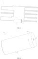
- FIG. 1 is a structural schematic diagram of a battery pack according to an embodiment of the present disclosure
- FIG. 2 is a partially enlarged view of Portion I of FIG. 1
- FIG. 3 is a structural schematic diagram of a spray system in FIG. 1
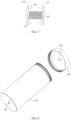
- FIG. 4 is a structural schematic diagram of a liquid storage device in FIG. 3
- FIG. 5 is a perspective view of FIG. 4
- FIG. 6 is an exploded view of FIG. 4
- FIG. 7 is a structural schematic diagram of a driving device in FIG. 6 when a limiting component is in a second working state
- FIG. 8 is a structural schematic diagram of a tank body and a cover body in FIG. 6 .
- the present disclosure provides a battery pack as shown in FIG. 1 .
- the battery pack includes a case (not shown) having an inner cavity, one or more battery units 2 disposed in the inner cavity of the case. In case of a plurality of battery units 2, they are arranged in a predetermined pattern and placed in the inner cavity of the case.
- the battery unit 2 is provided with a vent 21.
- a heat flow of high temperature and high pressure is generated inside the battery unit 2, and the vent 21 is used to discharge the heat flow, so as to reduce the risk of burning and explosion of the battery unit 2.
- the high-temperature heat flow may cause combustion of adjacent battery units 2.
- a spray system 1 is provided in the battery pack of the present disclosure to reduce spreading of the heat flow and improve safety of the battery pack.
- the spray system 1 includes a spray pipeline 11 which is disposed corresponding to the vent 21 of the battery unit 2. That is, the spray pipeline 11 passes through each battery unit 2 and located directly above the vent 21 of each battery unit 2.
- the spray pipeline is configured to circulate a spray liquid and to form an opening for releasing the spray liquid when the spray pipeline 11 is heated.
- the spray system 1 further includes a liquid storage device 12, which communicates with the spray pipeline 11 and is used for storing the spray liquid.
- the spray system 1 further includes a driving device 13 configured to drive the spray liquid in the liquid storage device 12 to flow into the spray pipeline 11.
- the spray pipeline 11 when the battery unit 2 is thermally out of control and the heat flow is discharged from the vent 21 of the battery unit 2, the spray pipeline 11 is heated by the heat flow and thus forms an opening at a position corresponding to the vent 21. Then the spray liquid in the spray pipeline 11 is discharged through the opening to prevent the heat flow from spreading. At the same time, after the spray liquid in the spray pipeline 11 is discharged through the opening, the spray liquid in the liquid storage device 12 can enter the spray pipeline 11 under the effect of the driving device 13, and further be discharged through the opening of the spray pipeline 11, thereby further preventing the heat flow from spreading.
- the spray system 1 provided with the liquid storage device 12 and the driving device 13, not only the spray liquid in the spray pipeline 11 but also the spray liquid stored in the liquid storage device 12 can be sprayed, which greatly improves the effect of spraying. In this way, the risk of heat flow spreading when the battery unit 2 is thermally out of control can be lowered, and the safety of the battery pack can be improved.
- the spray pipeline 11 When the spray pipeline 11 is subjected to the heat flow and partially cracks or totally breaks at the impacted position, no matter how the spray pipeline 11 is broken, the discharge of the spray liquid can be achieved as long as the opening is formed. Further, when the spray pipeline 11 is subjected to a heat flow at a temperature of 500 °C or higher (for example, 660°C), the spray pipeline 11 can form the opening at a heated position. When the battery unit 2 of the battery pack is thermally out of control, if the heat flow ejected from the vent 21 of the battery unit 2 is at the temperature of 500 °C or higher, the spray pipeline 11 can form the opening.
- a heat flow at a temperature of 500 °C or higher for example, 660°C
- the liquid storage device 12 has two liquid outlets 123 communicating with two ends of the spray pipeline 11.
- the spray system 1 includes two liquid storage devices 12 each having liquid outlet 123s, and the liquid outlets 123 of the two liquid storage devices 12 communicate with two ends of the spray pipeline 11, respectively.
- an opening is formed in the spray pipeline 11 corresponding to the vent 21 of this battery unit 2 under the heat flow.
- a closed loop is formed by the spray pipeline 11 and the one or more liquid storage devices 12. That is, the spray liquid that enters the spray pipeline 11 from both ends of the spray pipeline 11 can be discharged through the opening, thereby further increasing a discharging flow amount of the spray liquid. In this way, the spray liquid can be quickly discharged when an opening is formed at any position of the spray pipeline 11, thereby improving the response speed.
- the spray system 1 when the spray system 1 includes one liquid storage device 12 and the liquid storage device 12 has two liquid outlets 123, the two liquid outlets 123 are disposed at both ends of the liquid storage device 12 in an axial direction.
- the driving device 13 is disposed in the inner cavity of the liquid storage device 12, and the driving device 13 includes two driving plates 131, which are disposed along the axial direction and movable towards the corresponding liquid outlet 123, respectively.
- the two driving plates 131 of the driving device 13 are disposed in the inner cavity of the liquid storage device 12, and respectively move towards the corresponding liquid outlet 123 when the liquid storage device 12 is filled with the spray liquid.
- the left driving plate 131 moves to the left side
- the right driving plate 131 moves to the right side.
- the spray liquid in the liquid storage device 12 can be pushed into the spray pipeline 11 from the corresponding liquid outlet 123.
- the driving plate 131 applies thrust to the spray liquid in the liquid storage device 12 and the spray pipeline 11, so as to drive the spray liquid to be discharged through the spray pipeline 11, thereby achieving spraying.
- the driving device 13 further includes an elastic component 132 and a limiting component 133. Two ends of the elastic component 132 are connected to the two driving plates 131, respectively.
- the limiting component 133 has a first working state and a second working state. In the first working state, the limiting component 133 can limit a distance between the two driving plates 131 in such a manner that the elastic component 132 is in a compressed state, i.e., the limiting component 133 acts on the two driving plates 131 such that the two driving plates 131 are close to each other and thus compress the elastic component 132.
- the limiting component 133 can release restriction on the distance between the two driving plates 131, i.e., the limiting component 133 releases the restriction on the driving plates 131 and thus the elastic component 132, such that the elastic component 132 can be restored to an initial state (elongation).
- the driving device 13 includes two driving plates 131, the elastic component 132 and the limiting component 133.
- the elastic component 132 between the two driving plates 131 is in the compressed state, such that the driving device 13 stores the elastic potential energy.
- the elastic force of the elastic component 132 in the driving device 13 is equal to a sum of a hydraulic pressure of the spray liquid on the driving plates 131 and a pulling force of the limiting component 133 on the driving plates 131, so that the elastic component 132 can be maintained in the compressed state.
- the spray system 1 does not need to be provided with a sensor.
- the spraying can be achieved with the relationship between the components of the spray system 1, and the response speed is fast and the structure is simple.
- the limiting component 133 functions to limit the distance between the two driving plates 131.
- the limiting component 133 can include a glue material disposed between a peripheral wall of the driving plates 133 and an inner wall of the liquid storage device 12, so that the driving plates 133 and the liquid storage device 12 can be adhered together.
- the limiting component 133 is in the first working state, as shown in FIG. 6 .
- the opening is formed in the spray pipeline 11
- the adhesion effect generated by the glue material between the driving plates 133 and the liquid storage device 12 is removed under the effect of the elastic component 132, and the limiting component 133 is in the second working state, as shown in FIG. 7 .
- the glue material can be glue or adhesive tape.
- the adhesive force of the glue material exerted on the driving plates 131 and the liquid storage device 12 can be changed by setting parameters such as an amount of glue or an area of the adhesive tape. In this way, after the opening is formed in the spray pipeline 11, the glue material will lose the effect after a predetermined period (for example, the glue material will be invalid in 5 minutes after the opening is formed in the spray pipeline 11).
- the limiting component 133 can also be a strip structure connected between the two driving plates 131, and the limiting component 133 is provided with several breaking points 133a.
- the limiting component 133 is not broken yet at the breaking points 133a, and the limiting component 133 is in the first working state.
- the driving plates 131 has a tendency to move in an opposite direction under the effect of the elastic component 132, so that the limiting component 133 is broken at the break points 133a, and the limiting component 133 is in the second working state.
- the elastic component 132 can be a spring, an elastic foam or the like, as long as it can be elastically deformed.
- the elastic component 132 is preferably a constant force spring, which has a nearly constant elastic force with a change of the expansion and contraction amount. Therefore, in the driving device 13, the elastic component 132 can provide a constant elastic force rather than a gradually reduced elastic force during elongation, thereby further promoting the spray liquid to enter spray pipeline 11 from the liquid storage device 2.
- the driving plates 131 can be disposed in the liquid storage device 12 in such way that when the opening is formed in the spray pipeline 11, the driving plates 131 can move axially along the inner wall of the liquid storage device 12, and when no opening is formed in the spray pipeline 11 yet, the spray liquid cannot flow or flow with a low flow rate between the peripheral wall of the driving plates 131 and the inner wall of the liquid storage device 12, such that the liquid pressure of the spray liquid is affected to a small extent. That is, when no opening is formed in the spray pipeline 11 yet, there is no spray liquid or only a small amount of spray liquid is present between the two driving plates 131.
- a dynamic sealing structure (for example, a packing sealing or the like) can be disposed between the driving plates 131 and the liquid storage device 12, so that the driving plates 131 can move with respect to the inner wall of the liquid storage device 12 and the dynamic sealing structure has the sealing effect to prevent the spray liquid from entering the space between the two driving plates 131.
- the distances between the two driving plates 131 and the corresponding liquid outlets 123 are equal, i.e., the driving device 13 is at the middle position of the liquid storage device 12 along the axial direction.
- the hydraulic pressures received by the two driving plates 131 are substantially equal, which is conducive to maintaining the balance of the driving device 13 when no opening is formed in the spray pipeline 11 and also enables the spray liquid to be discharged from the two liquid outlets 123 when the opening is formed in the spray pipeline 11.
- the liquid storage device 12 has two oppositely disposed liquid outlets 123, which are connected to the spray pipeline 11 to form a closed loop. In such an embodiment, it is merely required to provide one liquid storage device 12 and one driving device 13 in order to discharge the spray liquid from the two liquid outlets 123 of the liquid storage device 12.
- Such configuration has advantages of a simple structure, space saving, low cost, and uneasy failure.
- the liquid storage device 12 may be embodied as a liquid storage tank. As shown in FIG. 8 , the liquid storage device includes a tank body 121 and a cover body 122, and the tank body 121 and the cover body 122 can be connected via a threaded connection, a clamping connection or the like.
- the liquid storage device 12 is required to satisfy a high sealing performance and can withstand a relatively high pressure. In an embodiment, it can be made of a metal material having high pressure resistance such as iron or stainless steel, and can also be made of a plastic material such as polypropylene (PP).
- the liquid storage device 12, when being made of stainless steel, can be formed as an integral structure with the spray pipeline 11, or can be connected with the spray pipeline 11 by welding. When the liquid storage device 12 is made of a plastic material such as PP, the liquid storage device 12 and the spray pipeline 11 can be connected by a push-in fitting.
- the spray system 1 as shown in FIG. 3 may be installed according to the following procedures: Firstly, the spray pipeline 11 is installed and then welded with the liquid storage device 12, so as to ensure a communication and a fluent flowing pathway between the spray pipeline 11 and the liquid outlets 123 of the liquid storage device 12; secondly, one end of the spray pipeline 11 is sealed with a cover or tape, and the spray liquid is filled into the liquid storage device 12 through the other end until reaching a level at a scale mark in the liquid storage device 12 (the scale mark is at such a position that the driving device 13 can be located at the middle position of the liquid storage device 12), then the driving device 13 is placed into the liquid storage device 12, and the limiting component 133 is placed in the first working state (the elastic component 132 is in the compressed state); thirdly, the cover body 122 of the liquid storage device 12 having thread is tightened with the tank body 121, and the spray liquid is further added through the spray pipeline 11 until the entire system is filled with the spray liquid; and fourthly, the other end of the spray pipeline 11 and the liquid storage
- the liquid storage device 12 is merely provided with one liquid outlet.
- the liquid storage device 12 includes a first end and a second end opposite to the first end.
- the first and second ends are disposed along an axial direction.
- the second end is closed, and the first end is provided with a liquid outlet 123 communicating with the spray pipeline 11.
- the driving device 13 is disposed in the inner cavity of the liquid storage device 12, and the driving device 13 includes a driving plate 131, an elastic component 132 and a limiting component 133. Two ends of the elastic component 132 are respectively connected to the driving plate 131 and the second end.
- the limiting component 133 has a first working state and a second working state.
- the limiting component 133 can limit a distance between the driving plate 131 and the second end, so as to bring the elastic component 132 in the compressed state.
- the limiting component 133 can release the restriction on the driving plate 131, such that the driving plate 131 can move towards the liquid outlet 123.
- the liquid storage device 12 merely has one liquid outlet 123, and the spray liquid can be discharged only through this liquid outlet 123.
- both ends of the spray pipeline 11 are respectively connected to the liquid storage device 12 as described in the second embodiment, i.e., the spray system 1 includes two liquid storage devices 12 and two driving devices 13.
- the spray liquid in the liquid storage device 12 and the spray pipeline 11 is a fluorinated liquid.
- the fluorinated liquid after being sprayed from the spray pipeline 11, can chemically react with the heat flow of the battery unit 2, thereby absorbing heat and preventing heat from spreading.
- the embodiments of the present disclosure further provide a spray system 1 as shown in FIG. 3 .
- the spray system includes a spray pipeline 11 configured to circulate a spray liquid and form an opening under heating for use in discharging of the spray liquid; a liquid storage device 12 communicating with the spray pipeline 11 and configured to store the spray liquid; and a driving device 13 configured to drive the spray liquid in the liquid storage device 12 to flow into the spray pipeline 11.
- the spray system 1 can be applied in the battery pack to prevent the heat flow from spreading when the battery unit 2 in the battery pack is thermally out of control, thereby extinguishing fire.
- the spray system 1 can also be used in other occasions where fire extinguishing is required.
Landscapes
- Chemical & Material Sciences (AREA)
- Chemical Kinetics & Catalysis (AREA)
- Electrochemistry (AREA)
- General Chemical & Material Sciences (AREA)
- Health & Medical Sciences (AREA)
- Public Health (AREA)
- Business, Economics & Management (AREA)
- Emergency Management (AREA)
- Engineering & Computer Science (AREA)
- Manufacturing & Machinery (AREA)
- Aviation & Aerospace Engineering (AREA)
- Battery Mounting, Suspending (AREA)
Description
- The present disclosure relates to the technical field of energy storage devices, and more particularly, to a spray system for a battery pack and a battery pack.
- At present, electric vehicle accidents frequently occur, which are mainly caused by spontaneous combustion of batteries. A battery includes a box body and a battery unit located inside the box body. As the energy density of the battery is gradually increased, the chemical system of the battery unit tends to have a higher energy density, and thus have a much larger volume. However, when the thermal failure occurs, the battery unit with a high energy density releases high-temperature heat flow. The high-temperature heat flow is prone to combustion when it comes into contact with air, and can further spread to adjacent battery units, thereby causing the whole battery pack to burn and thus putting the passengers and driver in danger. Prior art documents
US6340058B1 andCN202185099U are considered as relevant. - In view of above, the present disclosure provides a spray system for a battery pack and a battery pack, in order to solve problems of the burning of adjacent battery units and the personal safety of the passenger caused by the heat flow spreading during thermal failure.
- In a first aspect of the present disclosure, a spray system for a battery pack is provided as recited in claim 1.
- Preferably, the driving device further includes a limiting component having a first working state and a second working state. In the first working state, the limiting component acts on the two driving plates to limit a distance between the two driving plates in such a manner that the elastic component is brought to a compressed state. In the second working state, the limiting component does not act on the two driving plates, and the distance between the two driving plates increases under the elastic force applied by the elastic component.
- Preferably, the elastic component is one or more of a hydraulic spring, a constant force spring, or an elastic foam.
- Preferably, two ends of the limiting component are respectively connected to the two driving plates, and the limiting component is provided with several breaking points, at each of which the limiting component is breakable; or the limiting component includes a glue material, through which a peripheral wall of each of the two driving plates and an inner wall of the liquid storage device are adhered together.
- Preferably, a sliding seal structure is provided between a peripheral wall of each of the two driving plates and an inner wall of the liquid storage device.
- Preferably, each of the two driving plates has a same distance from its respective one of the liquid outlets when the limiting component is in the first working state.
- Preferably, the spray liquid in the liquid storage device and the spray pipeline is a fluorinated liquid.
- In a second aspect of the present disclosure, a battery pack is provided. The battery pack includes a case having an inner cavity, a battery unit disposed in the inner cavity of the case and including a vent, and a spray system according to the first aspect. The spray pipeline of the spray system is provided in association with the vent.
- In the present application, when a battery unit is thermally out of control and heat flow is discharged from its vent, under the effect of the heat flow, a spray pipeline can form an opening at a position corresponding to the vent under heating, such that spray liquid in the spray pipeline can be discharged through the opening, preventing the heat flow from spreading. In the meantime, after the spray liquid in the spray pipeline is discharged through the opening, the driving device can drive the spray liquid stored in the liquid storage device to flow into the spray pipeline and to be discharged through the opening of the spray pipeline, further preventing the heat flow from spreading.
- Therefore, in the present spray system provided with the liquid storage device and the driving device, not only the spray liquid in the spray pipeline but also the spray liquid in the liquid storage device can be discharged to achieve spray. In this way, the spray effect is improved, and heat flow generated when one battery unit is thermally out of control is prevented from spreading to adjacent battery units, thereby improving the safety of the battery pack.
- In order to more clearly illustrate technical solutions of embodiments of the present disclosure, the accompanying drawings used in the embodiments are briefly described below. The drawings described below are merely a part of the embodiments of the present disclosure. Based on these drawings, those skilled in the art can obtain other drawings without any creative effort.
-
FIG. 1 is a structural schematic diagram of a battery pack according to an embodiment of the present disclosure; -
FIG. 2 is a partially enlarged view of Portion I ofFIG. 1 ; -
FIG. 3 is a structural schematic diagram of a spray system inFIG. 1 ; -
FIG. 4 is a structural schematic diagram of a liquid storage device inFIG. 3 ; -
FIG. 5 is a perspective view ofFIG. 4 ; -
FIG. 6 is an exploded view ofFIG. 4 ; -
FIG. 7 is a structural schematic diagram of a driving device inFIG. 6 when a limiting component is in a second working state; and -
FIG. 8 is a structural schematic diagram of a tank body and a cover body inFIG. 6 . - Reference signs:
- 1 - spray system;
- 11 - spray pipeline;
- 12 - liquid storage device;
- 121 - tank body;
- 122 - cover body;
- 123 - liquid outlet;
- 13 - driving device;
- 131 - driving plate;
- 132 - elastic component;
- 133 - limiting component;
133a - breaking point;
- 2 - battery unit;
21 - vent. - In order to better understand technical solutions of the present disclosure, the embodiments of the present disclosure are described in details with reference to the drawings.
- It should be clear that the described embodiments are merely part of the embodiments of the present disclosure rather than all of the embodiments.
- The terms used in the embodiments of the present disclosure are merely for the purpose of describing specific embodiments, rather than limiting the present disclosure. The singular form "a", "an", "the" and "said" used in the embodiments and claims shall be interpreted as also including the plural form, unless indicated otherwise in the context.
- It should be understood that, the term "and/or" is used in the present disclosure merely to describe relations between associated objects, and thus includes three types of relations. That is, A and/or B can represents: (a) A exists alone; (b) A and B exist at the same time; or (c) B exists alone. In addition, the character "/" generally indicates "or".
- It should be understood that, the term such as "upper", "lower", "left", "right" and the like are used to indicate positions shown in the drawing, instead of being construed as limitations of the embodiment of the present disclosure. In addition, when an element is described as being "on" or "under" another element in the context, it should be understood that the element can be directly or via an intermediate element located "on" or "under" another element.
- When battery units in the battery pack are thermally out of control, the battery pack is likely to be burned, which may put the vehicle and the passengers in danger. In the present disclosure, the safety of the battery pack is improved mainly by providing the battery pack with an additional spray system.
-
FIG. 1 is a structural schematic diagram of a battery pack according to an embodiment of the present disclosure;FIG. 2 is a partially enlarged view of Portion I ofFIG. 1 ;FIG. 3 is a structural schematic diagram of a spray system inFIG. 1 ;FIG. 4 is a structural schematic diagram of a liquid storage device inFIG. 3 ;FIG. 5 is a perspective view ofFIG. 4 ;FIG. 6 is an exploded view ofFIG. 4 ;FIG. 7 is a structural schematic diagram of a driving device inFIG. 6 when a limiting component is in a second working state; andFIG. 8 is a structural schematic diagram of a tank body and a cover body inFIG. 6 . - The present disclosure provides a battery pack as shown in
FIG. 1 . The battery pack includes a case (not shown) having an inner cavity, one ormore battery units 2 disposed in the inner cavity of the case. In case of a plurality ofbattery units 2, they are arranged in a predetermined pattern and placed in the inner cavity of the case. - As shown in
FIG. 2 , in the battery pack, thebattery unit 2 is provided with avent 21. When thebattery unit 2 is thermally out of control, a heat flow of high temperature and high pressure is generated inside thebattery unit 2, and thevent 21 is used to discharge the heat flow, so as to reduce the risk of burning and explosion of thebattery unit 2. Once the heat flow is discharged from thevent 21, the high-temperature heat flow may cause combustion ofadjacent battery units 2. In order to reduce the risk of burning theadjacent units 2 when acertain battery unit 2 is out of control, a spray system 1 is provided in the battery pack of the present disclosure to reduce spreading of the heat flow and improve safety of the battery pack. - Specifically, as shown in
FIG. 1 andFIG. 3 , the spray system 1 includes aspray pipeline 11 which is disposed corresponding to thevent 21 of thebattery unit 2. That is, thespray pipeline 11 passes through eachbattery unit 2 and located directly above thevent 21 of eachbattery unit 2. The spray pipeline is configured to circulate a spray liquid and to form an opening for releasing the spray liquid when thespray pipeline 11 is heated. Meanwhile, as shown inFIG. 3 , the spray system 1 further includes aliquid storage device 12, which communicates with thespray pipeline 11 and is used for storing the spray liquid. The spray system 1 further includes a drivingdevice 13 configured to drive the spray liquid in theliquid storage device 12 to flow into thespray pipeline 11. - According to the present disclosure, when the
battery unit 2 is thermally out of control and the heat flow is discharged from thevent 21 of thebattery unit 2, thespray pipeline 11 is heated by the heat flow and thus forms an opening at a position corresponding to thevent 21. Then the spray liquid in thespray pipeline 11 is discharged through the opening to prevent the heat flow from spreading. At the same time, after the spray liquid in thespray pipeline 11 is discharged through the opening, the spray liquid in theliquid storage device 12 can enter thespray pipeline 11 under the effect of the drivingdevice 13, and further be discharged through the opening of thespray pipeline 11, thereby further preventing the heat flow from spreading. - In the spray system 1 provided with the
liquid storage device 12 and the drivingdevice 13, not only the spray liquid in thespray pipeline 11 but also the spray liquid stored in theliquid storage device 12 can be sprayed, which greatly improves the effect of spraying. In this way, the risk of heat flow spreading when thebattery unit 2 is thermally out of control can be lowered, and the safety of the battery pack can be improved. - When the
spray pipeline 11 is subjected to the heat flow and partially cracks or totally breaks at the impacted position, no matter how thespray pipeline 11 is broken, the discharge of the spray liquid can be achieved as long as the opening is formed. Further, when thespray pipeline 11 is subjected to a heat flow at a temperature of 500 °C or higher (for example, 660°C), thespray pipeline 11 can form the opening at a heated position. When thebattery unit 2 of the battery pack is thermally out of control, if the heat flow ejected from thevent 21 of thebattery unit 2 is at the temperature of 500 °C or higher, thespray pipeline 11 can form the opening. - Further, in the first embodiment as shown in
FIG. 3 , theliquid storage device 12 has twoliquid outlets 123 communicating with two ends of thespray pipeline 11. In another embodiment, the spray system 1 includes twoliquid storage devices 12 each having liquid outlet 123s, and theliquid outlets 123 of the twoliquid storage devices 12 communicate with two ends of thespray pipeline 11, respectively. - In the present embodiment, when a
certain battery unit 2 in the battery pack is thermally out of control and discharges the heat flow, an opening is formed in thespray pipeline 11 corresponding to thevent 21 of thisbattery unit 2 under the heat flow. When both ends of thespray pipeline 11 communicate with one or moreliquid storage devices 12, a closed loop is formed by thespray pipeline 11 and the one or moreliquid storage devices 12. That is, the spray liquid that enters thespray pipeline 11 from both ends of thespray pipeline 11 can be discharged through the opening, thereby further increasing a discharging flow amount of the spray liquid. In this way, the spray liquid can be quickly discharged when an opening is formed at any position of thespray pipeline 11, thereby improving the response speed. - In the embodiment as shown in
FIG. 3 , when the spray system 1 includes oneliquid storage device 12 and theliquid storage device 12 has twoliquid outlets 123, the twoliquid outlets 123 are disposed at both ends of theliquid storage device 12 in an axial direction. In the meantime, as shown inFIG. 5 and FIG. 6 , the drivingdevice 13 is disposed in the inner cavity of theliquid storage device 12, and the drivingdevice 13 includes two drivingplates 131, which are disposed along the axial direction and movable towards the correspondingliquid outlet 123, respectively. - In the embodiment as shown in
FIG. 5 , the two drivingplates 131 of the drivingdevice 13 are disposed in the inner cavity of theliquid storage device 12, and respectively move towards the correspondingliquid outlet 123 when theliquid storage device 12 is filled with the spray liquid. For example, inFIG. 5 , theleft driving plate 131 moves to the left side and theright driving plate 131 moves to the right side. During the movement of the drivingplates 131, the spray liquid in theliquid storage device 12 can be pushed into thespray pipeline 11 from the correspondingliquid outlet 123. In other words, the drivingplate 131 applies thrust to the spray liquid in theliquid storage device 12 and thespray pipeline 11, so as to drive the spray liquid to be discharged through thespray pipeline 11, thereby achieving spraying. - Further, in order to enable the two driving
plates 131 to move towards the correspondingliquid outlet 123, as shown inFIG. 5 and FIG. 6 , the drivingdevice 13 further includes anelastic component 132 and a limitingcomponent 133. Two ends of theelastic component 132 are connected to the two drivingplates 131, respectively. At the same time, the limitingcomponent 133 has a first working state and a second working state. In the first working state, the limitingcomponent 133 can limit a distance between the two drivingplates 131 in such a manner that theelastic component 132 is in a compressed state, i.e., the limitingcomponent 133 acts on the two drivingplates 131 such that the two drivingplates 131 are close to each other and thus compress theelastic component 132. In the second working state, the limitingcomponent 133 can release restriction on the distance between the two drivingplates 131, i.e., the limitingcomponent 133 releases the restriction on the drivingplates 131 and thus theelastic component 132, such that theelastic component 132 can be restored to an initial state (elongation). - In the present disclosure, the driving
device 13 includes two drivingplates 131, theelastic component 132 and the limitingcomponent 133. In the initial state (i.e., the limitingcomponent 133 is in the first working state), theelastic component 132 between the two drivingplates 131 is in the compressed state, such that the drivingdevice 13 stores the elastic potential energy. When no opening is formed in the spray pipeline 11 (thebattery unit 2 is not thermally out of control yet), in the inner cavity of theliquid storage device 12, the elastic force of theelastic component 132 in the drivingdevice 13 is equal to a sum of a hydraulic pressure of the spray liquid on the drivingplates 131 and a pulling force of the limitingcomponent 133 on the drivingplates 131, so that theelastic component 132 can be maintained in the compressed state. When an opening is formed in thespray pipeline 11 and the spray liquid is discharged through the opening, the hydraulic pressure in theliquid storage device 12 is reduced such that the balance is broken. Then, under a restoring force of theelastic component 132, the restriction of the limiting component 133 (which is in the second working state) is overcame, and the elastic potential energy of theelastic component 132 is converted into a kinetic energy for the drivingplates 131, so that the two drivingplates 131 are driven to move towards theliquid outlets 123 to drive the spray liquid to be discharged. - Therefore, there is need to provide the spray system 1 according to the present disclosure with a monitoring device and a control device. That is, the spray system 1 does not need to be provided with a sensor. The spraying can be achieved with the relationship between the components of the spray system 1, and the response speed is fast and the structure is simple.
- In the present disclosure, the limiting
component 133 functions to limit the distance between the two drivingplates 131. Thus, in the first embodiment, the limitingcomponent 133 can include a glue material disposed between a peripheral wall of the drivingplates 133 and an inner wall of theliquid storage device 12, so that the drivingplates 133 and theliquid storage device 12 can be adhered together. At this moment, the limitingcomponent 133 is in the first working state, as shown inFIG. 6 . When the opening is formed in thespray pipeline 11, the adhesion effect generated by the glue material between the drivingplates 133 and theliquid storage device 12 is removed under the effect of theelastic component 132, and the limitingcomponent 133 is in the second working state, as shown inFIG. 7 . - In an embodiment, the glue material can be glue or adhesive tape. The adhesive force of the glue material exerted on the driving
plates 131 and theliquid storage device 12 can be changed by setting parameters such as an amount of glue or an area of the adhesive tape. In this way, after the opening is formed in thespray pipeline 11, the glue material will lose the effect after a predetermined period (for example, the glue material will be invalid in 5 minutes after the opening is formed in the spray pipeline 11). - In the second embodiment as shown in
FIG. 5 and FIG. 6 , the limitingcomponent 133 can also be a strip structure connected between the two drivingplates 131, and the limitingcomponent 133 is provided withseveral breaking points 133a. When no opening is formed in thespray pipeline 11, the limitingcomponent 133 is not broken yet at thebreaking points 133a, and the limitingcomponent 133 is in the first working state. When an opening is formed in thespray pipeline 11, the drivingplates 131 has a tendency to move in an opposite direction under the effect of theelastic component 132, so that the limitingcomponent 133 is broken at thebreak points 133a, and the limitingcomponent 133 is in the second working state. - In another aspect, the
elastic component 132 can be a spring, an elastic foam or the like, as long as it can be elastically deformed. Further, in the embodiment shown inFIG. 5 and FIG. 6 , theelastic component 132 is preferably a constant force spring, which has a nearly constant elastic force with a change of the expansion and contraction amount. Therefore, in the drivingdevice 13, theelastic component 132 can provide a constant elastic force rather than a gradually reduced elastic force during elongation, thereby further promoting the spray liquid to enterspray pipeline 11 from theliquid storage device 2. - As shown in
FIG. 5 , the drivingplates 131 can be disposed in theliquid storage device 12 in such way that when the opening is formed in thespray pipeline 11, the drivingplates 131 can move axially along the inner wall of theliquid storage device 12, and when no opening is formed in thespray pipeline 11 yet, the spray liquid cannot flow or flow with a low flow rate between the peripheral wall of the drivingplates 131 and the inner wall of theliquid storage device 12, such that the liquid pressure of the spray liquid is affected to a small extent. That is, when no opening is formed in thespray pipeline 11 yet, there is no spray liquid or only a small amount of spray liquid is present between the two drivingplates 131. - In a specific embodiment, a dynamic sealing structure (for example, a packing sealing or the like) can be disposed between the driving
plates 131 and theliquid storage device 12, so that the drivingplates 131 can move with respect to the inner wall of theliquid storage device 12 and the dynamic sealing structure has the sealing effect to prevent the spray liquid from entering the space between the two drivingplates 131. - In another aspect, as shown in
FIG. 5 , when no opening is formed in thespray pipeline 11 yet and the limitingcomponent 133 is still in the first working state, the distances between the two drivingplates 131 and the correspondingliquid outlets 123 are equal, i.e., the drivingdevice 13 is at the middle position of theliquid storage device 12 along the axial direction. In this regard, the hydraulic pressures received by the two drivingplates 131 are substantially equal, which is conducive to maintaining the balance of the drivingdevice 13 when no opening is formed in thespray pipeline 11 and also enables the spray liquid to be discharged from the twoliquid outlets 123 when the opening is formed in thespray pipeline 11. - In the above embodiment, the
liquid storage device 12 has two oppositely disposedliquid outlets 123, which are connected to thespray pipeline 11 to form a closed loop. In such an embodiment, it is merely required to provide oneliquid storage device 12 and onedriving device 13 in order to discharge the spray liquid from the twoliquid outlets 123 of theliquid storage device 12. Such configuration has advantages of a simple structure, space saving, low cost, and uneasy failure. - In this embodiment, the
liquid storage device 12 may be embodied as a liquid storage tank. As shown inFIG. 8 , the liquid storage device includes atank body 121 and acover body 122, and thetank body 121 and thecover body 122 can be connected via a threaded connection, a clamping connection or the like. Theliquid storage device 12 is required to satisfy a high sealing performance and can withstand a relatively high pressure. In an embodiment, it can be made of a metal material having high pressure resistance such as iron or stainless steel, and can also be made of a plastic material such as polypropylene (PP). Theliquid storage device 12, when being made of stainless steel, can be formed as an integral structure with thespray pipeline 11, or can be connected with thespray pipeline 11 by welding. When theliquid storage device 12 is made of a plastic material such as PP, theliquid storage device 12 and thespray pipeline 11 can be connected by a push-in fitting. - The spray system 1 as shown in
FIG. 3 may be installed according to the following procedures: Firstly, the spray pipeline 11 is installed and then welded with the liquid storage device 12, so as to ensure a communication and a fluent flowing pathway between the spray pipeline 11 and the liquid outlets 123 of the liquid storage device 12; secondly, one end of the spray pipeline 11 is sealed with a cover or tape, and the spray liquid is filled into the liquid storage device 12 through the other end until reaching a level at a scale mark in the liquid storage device 12 (the scale mark is at such a position that the driving device 13 can be located at the middle position of the liquid storage device 12), then the driving device 13 is placed into the liquid storage device 12, and the limiting component 133 is placed in the first working state (the elastic component 132 is in the compressed state); thirdly, the cover body 122 of the liquid storage device 12 having thread is tightened with the tank body 121, and the spray liquid is further added through the spray pipeline 11 until the entire system is filled with the spray liquid; and fourthly, the other end of the spray pipeline 11 and the liquid storage device 12 are fixedly sealed by welding to complete the overall sealing. - In a second embodiment, the
liquid storage device 12 is merely provided with one liquid outlet. Theliquid storage device 12 includes a first end and a second end opposite to the first end. The first and second ends are disposed along an axial direction. The second end is closed, and the first end is provided with aliquid outlet 123 communicating with thespray pipeline 11. In this embodiment, the drivingdevice 13 is disposed in the inner cavity of theliquid storage device 12, and the drivingdevice 13 includes a drivingplate 131, anelastic component 132 and a limitingcomponent 133. Two ends of theelastic component 132 are respectively connected to the drivingplate 131 and the second end. The limitingcomponent 133 has a first working state and a second working state. In the first working state, the limitingcomponent 133 can limit a distance between the drivingplate 131 and the second end, so as to bring theelastic component 132 in the compressed state. In the second working state, the limitingcomponent 133 can release the restriction on the drivingplate 131, such that the drivingplate 131 can move towards theliquid outlet 123. - In the spray system 1 according to the present embodiment, the
liquid storage device 12 merely has oneliquid outlet 123, and the spray liquid can be discharged only through thisliquid outlet 123. In order to improve the spraying effect, both ends of thespray pipeline 11 are respectively connected to theliquid storage device 12 as described in the second embodiment, i.e., the spray system 1 includes twoliquid storage devices 12 and twodriving devices 13. - In another aspect, in the above embodiment, the spray liquid in the
liquid storage device 12 and thespray pipeline 11 is a fluorinated liquid. The fluorinated liquid, after being sprayed from thespray pipeline 11, can chemically react with the heat flow of thebattery unit 2, thereby absorbing heat and preventing heat from spreading. - In addition, the embodiments of the present disclosure further provide a spray system 1 as shown in
FIG. 3 . The spray system includes aspray pipeline 11 configured to circulate a spray liquid and form an opening under heating for use in discharging of the spray liquid; aliquid storage device 12 communicating with thespray pipeline 11 and configured to store the spray liquid; and adriving device 13 configured to drive the spray liquid in theliquid storage device 12 to flow into thespray pipeline 11. - The spray system 1 can be applied in the battery pack to prevent the heat flow from spreading when the
battery unit 2 in the battery pack is thermally out of control, thereby extinguishing fire. The spray system 1 can also be used in other occasions where fire extinguishing is required. - The above-described embodiments are merely preferable embodiments, but not intended to provide any limitation.
Claims (8)
- A spray system (1) for a battery pack, characterized in comprising:a spray pipeline (11) configured to circulate a spray liquid and forming an opening when being heated;a liquid storage device (12) comprising two liquid outlets (123) that are located at two ends of the liquid storage device (12) along an axial direction thereof and communicate with two ends of the spray pipeline (11), respectively; anda driving device (13) disposed in an inner cavity of the liquid storage device (12) and comprising a driving component and an elastic component (132) connected to the driving component, wherein the driving component comprises two driving plates (131) disposed along the axial direction, the two driving plates (131) being respectively connected to two ends of the elastic component (132) and each movable towards a respective one of the two liquid outlets (123),wherein the two driving plates (131), under an elastic force applied by the elastic component (132), drives the spray liquid in the liquid storage device (12) to flow into the spray pipeline (11).
- The spray system (1) according to claim 1, characterized in that the driving device (13) further comprises a limiting component (133) having a first working state and a second working state,in the first working state, the limiting component (133) acts on the two driving plates (131) to limit a distance between the two driving plates (131) in such a manner that the elastic component (132) is brought to a compressed state, andin the second working state, the limiting component (133) does not act on the two driving plates (131), and the distance between the two driving plates (131) increases under the elastic force applied by the elastic component (132).
- The spray system (1) according to claim 2, characterized in that the elastic component (132) is one or more of a hydraulic spring, a constant force spring, or an elastic foam.
- The spray system (1) according to claim 2, characterized in that two ends of the limiting component (133) are respectively connected to the two driving plates (131), and the limiting component (133) is provided with several breaking points, at each of which the limiting component (133) is breakable, or
the limiting component (133) comprises a glue material, through which a peripheral wall of each of the two driving plates (131) and an inner wall of the liquid storage device (12) are adhered together. - The spray system (1) according to claim 2, characterized in that a sliding seal structure is provided between a peripheral wall of each of the two driving plates (131) and an inner wall of the liquid storage device (12).
- The spray system (1) according to claim 2, characterized in that each of the two driving plates (131) has a same distance from its respective one of the liquid outlets (123) when the limiting component (133) is in the first working state.
- The spray system (1) according to any one of claims 1 to 6, characterized in that the spray liquid in the liquid storage device (12) and the spray pipeline (11) is a fluorinated liquid.
- A battery pack, characterized in comprising:a case having an inner cavity;a battery unit (2) disposed in the inner cavity of the case and comprising a vent (21); anda spray system (1) according to any one of claims 1 to 7,wherein the spray pipeline (11) of the spray system (1) is provided in association with the vent (21).
Applications Claiming Priority (1)
| Application Number | Priority Date | Filing Date | Title |
|---|---|---|---|
| CN201811624585.9A CN111097115B (en) | 2018-12-28 | 2018-12-28 | A spray system for a battery pack and a battery pack |
Publications (3)
| Publication Number | Publication Date |
|---|---|
| EP3675214A1 EP3675214A1 (en) | 2020-07-01 |
| EP3675214B1 true EP3675214B1 (en) | 2024-12-25 |
| EP3675214C0 EP3675214C0 (en) | 2024-12-25 |
Family
ID=67145717
Family Applications (1)
| Application Number | Title | Priority Date | Filing Date |
|---|---|---|---|
| EP19184160.0A Active EP3675214B1 (en) | 2018-12-28 | 2019-07-03 | Battery pack and spray system for the same |
Country Status (5)
| Country | Link |
|---|---|
| US (1) | US11043708B2 (en) |
| EP (1) | EP3675214B1 (en) |
| CN (2) | CN111097115B (en) |
| HU (1) | HUE070232T2 (en) |
| WO (1) | WO2020135348A1 (en) |
Families Citing this family (8)
| Publication number | Priority date | Publication date | Assignee | Title |
|---|---|---|---|---|
| CN112331990B (en) * | 2019-09-26 | 2021-09-14 | 宁德时代新能源科技股份有限公司 | Battery pack, vehicle and control method for relieving thermal runaway spread of battery pack |
| USD943531S1 (en) * | 2020-10-16 | 2022-02-15 | Dongguan Shangyong Plastic Products Co., Ltd. | Battery box |
| WO2022082397A1 (en) * | 2020-10-19 | 2022-04-28 | 江苏时代新能源科技有限公司 | Battery, electric apparatus, and method and device for preparing battery |
| EP4075589B1 (en) | 2020-10-19 | 2026-02-25 | Jiangsu Contemporary Amperex Technology Limited | Battery, electric device, and battery manufacturing method and device |
| KR102646202B1 (en) | 2020-10-19 | 2024-03-12 | 지앙수 컨템포러리 엠퍼렉스 테크놀로지 리미티드 | Batteries, electrical devices, methods and devices for manufacturing batteries |
| HUE060296T2 (en) * | 2020-10-19 | 2023-02-28 | Jiangsu Contemporary Amperex Tech Ltd | Battery, electrical device, and method and device for preparing battery |
| CN113437398B (en) * | 2021-06-22 | 2023-05-12 | 广州小鹏汽车科技有限公司 | Battery thermal runaway treatment method, device, vehicle and medium |
| CN116505169B (en) * | 2023-06-20 | 2023-09-26 | 宁波齐云新材料技术有限公司 | A highly integrated lithium battery pack packaging structure and its working control method |
Citations (1)
| Publication number | Priority date | Publication date | Assignee | Title |
|---|---|---|---|---|
| CN202185099U (en) * | 2011-07-20 | 2012-04-11 | 国安达消防科技(厦门)有限公司 | Automatic fire extinguishing system with dual drive multi-nozzle pipe network |
Family Cites Families (30)
| Publication number | Priority date | Publication date | Assignee | Title |
|---|---|---|---|---|
| US6340058B1 (en) * | 2000-05-30 | 2002-01-22 | Stephen M. Dominick | Heat triggering fire suppressant device |
| CA2629356A1 (en) * | 2005-11-10 | 2007-05-24 | Great Lakes Chemical Corporation | Compositions ,combustion prevention compositions, methods for preventing and/or extinguishing combustion, combustion prevention systems, and production processes |
| JP4872820B2 (en) * | 2007-06-19 | 2012-02-08 | 株式会社Lixil | Electrical equipment |
| US8329325B2 (en) * | 2010-02-18 | 2012-12-11 | Denso International America, Inc. | Battery cooling with mist evaporation and condensation |
| CN102451532B (en) * | 2010-11-02 | 2013-09-18 | 林滨 | Portal and safe fire extinguishing bomb |
| KR20120056386A (en) * | 2010-11-25 | 2012-06-04 | 조남윤 | Grenade style hand grenade |
| WO2013036087A2 (en) * | 2011-09-08 | 2013-03-14 | 주식회사 엘지화학 | Apparatus for extinguishing a battery-pack fire |
| US20140060859A1 (en) * | 2012-08-30 | 2014-03-06 | Ei Du Pont De Nemours And Company | Mixture for Abating Combustion by a Li-ion Battery |
| CN103208602B (en) * | 2013-02-04 | 2015-04-08 | 力帆实业(集团)股份有限公司 | Self-extinguishing battery pack for electric automobile |
| TWI531104B (en) * | 2013-09-25 | 2016-04-21 | 原瑞電池科技股份有限公司 | Battery module |
| CN107112607B (en) * | 2015-01-16 | 2020-08-11 | 株式会社村田制作所 | Power storage modules, power storage systems, electronic devices, electric vehicles, and power systems |
| CN106785182B (en) * | 2015-11-23 | 2019-06-11 | 宁德时代新能源科技股份有限公司 | battery pack |
| CN205578813U (en) * | 2016-04-18 | 2016-09-14 | 龙口市汽柴油管厂 | Temperature sensing is from open -type shower valve |
| CN205598472U (en) * | 2016-04-27 | 2016-09-28 | 中汽客汽车零部件(厦门)有限公司 | A vehicle safety battery box and vehicle power safety system |
| CN105810859B (en) * | 2016-05-24 | 2018-03-20 | 宁德时代新能源科技股份有限公司 | Secondary battery top cap and secondary battery |
| CN205846173U (en) * | 2016-06-16 | 2016-12-28 | 广东合一新材料研究院有限公司 | The working medium cooling system by contact of capacity cell |
| CN206198507U (en) * | 2016-09-12 | 2017-05-31 | 深圳市西盟特电子有限公司 | A kind of bus inside fire-fighting system |
| CN206295523U (en) * | 2016-09-28 | 2017-07-04 | 江门市地尔汉宇电器股份有限公司 | A kind of automatic detection and the electrokinetic cell bag put out a fire |
| EP3530324A4 (en) * | 2016-10-18 | 2020-06-10 | Hitachi, Ltd. | Storage battery device for storage-battery electric railcar, and storage-battery electric railcar |
| JP2017060805A (en) * | 2016-11-16 | 2017-03-30 | ホーチキ株式会社 | Extinction system for electric vehicle |
| CN206388817U (en) * | 2016-12-02 | 2017-08-08 | 重庆壹特科技有限公司 | A kind of battery anti-explosion flame retardant systems |
| JP6662324B2 (en) * | 2017-02-17 | 2020-03-11 | トヨタ自動車株式会社 | Battery pack |
| KR101984817B1 (en) * | 2017-05-11 | 2019-05-31 | 주식회사 대경산전 | Automatic fire extinguishing systems for energy storage systems |
| CN206822989U (en) * | 2017-05-25 | 2018-01-02 | 惠州中科新能源研究院 | A kind of power module fire extinguishing structure |
| CN108159604A (en) * | 2017-11-27 | 2018-06-15 | 曙光节能技术(北京)股份有限公司 | A kind of system of included extinguishing device |
| CN207822303U (en) * | 2017-12-08 | 2018-09-07 | 中国石油化工股份有限公司 | Heat-proof device and insulation system |
| CN207785704U (en) * | 2017-12-22 | 2018-08-31 | 天津长芦新材料研究院有限公司 | Extinguishing device built in a kind of mechanical electronic equipment |
| CN108075084A (en) * | 2018-01-17 | 2018-05-25 | 华霆(合肥)动力技术有限公司 | Battery modules, extinguishing device and support construction |
| CN208141560U (en) * | 2018-03-20 | 2018-11-23 | 赖河波 | A kind of building monitoring alarm |
| CN108744344B (en) * | 2018-04-27 | 2021-03-09 | 中国科学技术大学 | A fire-fighting system of a lithium-based power battery |
-
2018
- 2018-12-28 CN CN201811624585.9A patent/CN111097115B/en active Active
- 2018-12-28 CN CN202110801952.3A patent/CN113521599A/en active Pending
-
2019
- 2019-07-03 HU HUE19184160A patent/HUE070232T2/en unknown
- 2019-07-03 EP EP19184160.0A patent/EP3675214B1/en active Active
- 2019-07-07 US US16/504,272 patent/US11043708B2/en active Active
- 2019-12-23 WO PCT/CN2019/127543 patent/WO2020135348A1/en not_active Ceased
Patent Citations (1)
| Publication number | Priority date | Publication date | Assignee | Title |
|---|---|---|---|---|
| CN202185099U (en) * | 2011-07-20 | 2012-04-11 | 国安达消防科技(厦门)有限公司 | Automatic fire extinguishing system with dual drive multi-nozzle pipe network |
Also Published As
| Publication number | Publication date |
|---|---|
| HUE070232T2 (en) | 2025-05-28 |
| US20200212524A1 (en) | 2020-07-02 |
| WO2020135348A1 (en) | 2020-07-02 |
| EP3675214A1 (en) | 2020-07-01 |
| US11043708B2 (en) | 2021-06-22 |
| CN111097115B (en) | 2021-08-20 |
| CN111097115A (en) | 2020-05-05 |
| EP3675214C0 (en) | 2024-12-25 |
| CN113521599A (en) | 2021-10-22 |
Similar Documents
| Publication | Publication Date | Title |
|---|---|---|
| EP3675214B1 (en) | Battery pack and spray system for the same | |
| US12029928B2 (en) | Spraying system of battery pack, and battery pack | |
| EP4123791B1 (en) | Box body, battery, electric device, and manufacturing method for battery | |
| CN107910606B (en) | A lithium-ion battery pack thermal runaway control device | |
| CN108807785B (en) | Power battery explosion-proof device, power battery and electric automobile | |
| KR102915772B1 (en) | Battery explosion-proof valve, battery plug-in box and electric apparatus | |
| KR20210154282A (en) | Apparatus for supplying fire extinguishing agent to high-voltage battery of vehicle | |
| JP2023529224A (en) | A thermally actuated pressure relief device (TPRD), a gas pressure tank, and a gas pressure tank system including the TPRD, and a method for thermal overpressure protection | |
| CN112103444A (en) | Box, battery, electric equipment and battery manufacturing method | |
| CN109718491A (en) | A kind of water mists battery case fire prevention and control device | |
| CN108543248B (en) | Battery system and automatic dry powder extinguishing device thereof | |
| AU2022319349A1 (en) | Starting apparatus and fire extinguishing device | |
| CN221009034U (en) | Battery package spray system and battery package that has it | |
| CN116510214A (en) | Indirect starting mechanism of fire extinguishing device and starting method thereof | |
| CN113217682B (en) | A self-feedback regulating valve device and fire extinguishing equipment | |
| CN217041147U (en) | Non-pressure-storage miniature fire extinguishing device | |
| JP4768856B2 (en) | Cold resistant container for fire extinguishing liquid | |
| WO2004080541A1 (en) | Automatic fire extinguisher | |
| RU130370U1 (en) | DEVICE FOR SUBMITTING A FLUID WORKING ENVIRONMENT | |
| CN222955831U (en) | Lithium battery fire extinguishing device and new energy power equipment provided with same | |
| CN219163496U (en) | Cooling device and battery pack | |
| CN111697178A (en) | New energy automobile battery box fixing device | |
| CN221130815U (en) | Pulse fire extinguishing device with feedback structure | |
| CN119951079A (en) | Active fire extinguishing bomb and charger | |
| CN121513392A (en) | Mechanical fire extinguishing devices and methods for use with small electric vehicles and simple batteries |
Legal Events
| Date | Code | Title | Description |
|---|---|---|---|
| PUAI | Public reference made under article 153(3) epc to a published international application that has entered the european phase |
Free format text: ORIGINAL CODE: 0009012 |
|
| STAA | Information on the status of an ep patent application or granted ep patent |
Free format text: STATUS: REQUEST FOR EXAMINATION WAS MADE |
|
| 17P | Request for examination filed |
Effective date: 20190703 |
|
| AK | Designated contracting states |
Kind code of ref document: A1 Designated state(s): AL AT BE BG CH CY CZ DE DK EE ES FI FR GB GR HR HU IE IS IT LI LT LU LV MC MK MT NL NO PL PT RO RS SE SI SK SM TR |
|
| AX | Request for extension of the european patent |
Extension state: BA ME |
|
| STAA | Information on the status of an ep patent application or granted ep patent |
Free format text: STATUS: EXAMINATION IS IN PROGRESS |
|
| 17Q | First examination report despatched |
Effective date: 20221222 |
|
| REG | Reference to a national code |
Ref country code: DE Ref legal event code: R079 Free format text: PREVIOUS MAIN CLASS: H01M0002100000 Ipc: A62C0003160000 Ref country code: DE Ref legal event code: R079 Ref document number: 602019063880 Country of ref document: DE Free format text: PREVIOUS MAIN CLASS: H01M0002100000 Ipc: A62C0003160000 |
|
| RIC1 | Information provided on ipc code assigned before grant |
Ipc: H01M 50/204 20210101ALI20240710BHEP Ipc: A62C 3/07 20060101ALI20240710BHEP Ipc: A62C 35/64 20060101ALI20240710BHEP Ipc: A62C 35/10 20060101ALI20240710BHEP Ipc: A62C 35/02 20060101ALI20240710BHEP Ipc: A62C 3/16 20060101AFI20240710BHEP |
|
| GRAP | Despatch of communication of intention to grant a patent |
Free format text: ORIGINAL CODE: EPIDOSNIGR1 |
|
| STAA | Information on the status of an ep patent application or granted ep patent |
Free format text: STATUS: GRANT OF PATENT IS INTENDED |
|
| RAP1 | Party data changed (applicant data changed or rights of an application transferred) |
Owner name: CONTEMPORARY AMPEREX TECHNOLOGY(HONG KONG) LIMITED |
|
| INTG | Intention to grant announced |
Effective date: 20240927 |
|
| GRAS | Grant fee paid |
Free format text: ORIGINAL CODE: EPIDOSNIGR3 |
|
| GRAA | (expected) grant |
Free format text: ORIGINAL CODE: 0009210 |
|
| STAA | Information on the status of an ep patent application or granted ep patent |
Free format text: STATUS: THE PATENT HAS BEEN GRANTED |
|
| AK | Designated contracting states |
Kind code of ref document: B1 Designated state(s): AL AT BE BG CH CY CZ DE DK EE ES FI FR GB GR HR HU IE IS IT LI LT LU LV MC MK MT NL NO PL PT RO RS SE SI SK SM TR |
|
| REG | Reference to a national code |
Ref country code: GB Ref legal event code: FG4D |
|
| REG | Reference to a national code |
Ref country code: CH Ref legal event code: EP |
|
| REG | Reference to a national code |
Ref country code: DE Ref legal event code: R096 Ref document number: 602019063880 Country of ref document: DE |
|
| REG | Reference to a national code |
Ref country code: IE Ref legal event code: FG4D |
|
| U01 | Request for unitary effect filed |
Effective date: 20250117 |
|
| U07 | Unitary effect registered |
Designated state(s): AT BE BG DE DK EE FI FR IT LT LU LV MT NL PT RO SE SI Effective date: 20250123 |
|
| PG25 | Lapsed in a contracting state [announced via postgrant information from national office to epo] |
Ref country code: HR Free format text: LAPSE BECAUSE OF FAILURE TO SUBMIT A TRANSLATION OF THE DESCRIPTION OR TO PAY THE FEE WITHIN THE PRESCRIBED TIME-LIMIT Effective date: 20241225 |
|
| PG25 | Lapsed in a contracting state [announced via postgrant information from national office to epo] |
Ref country code: NO Free format text: LAPSE BECAUSE OF FAILURE TO SUBMIT A TRANSLATION OF THE DESCRIPTION OR TO PAY THE FEE WITHIN THE PRESCRIBED TIME-LIMIT Effective date: 20250325 |
|
| PG25 | Lapsed in a contracting state [announced via postgrant information from national office to epo] |
Ref country code: GR Free format text: LAPSE BECAUSE OF FAILURE TO SUBMIT A TRANSLATION OF THE DESCRIPTION OR TO PAY THE FEE WITHIN THE PRESCRIBED TIME-LIMIT Effective date: 20250326 |
|
| PG25 | Lapsed in a contracting state [announced via postgrant information from national office to epo] |
Ref country code: RS Free format text: LAPSE BECAUSE OF FAILURE TO SUBMIT A TRANSLATION OF THE DESCRIPTION OR TO PAY THE FEE WITHIN THE PRESCRIBED TIME-LIMIT Effective date: 20250325 |
|
| REG | Reference to a national code |
Ref country code: HU Ref legal event code: AG4A Ref document number: E070232 Country of ref document: HU |
|
| PG25 | Lapsed in a contracting state [announced via postgrant information from national office to epo] |
Ref country code: SM Free format text: LAPSE BECAUSE OF FAILURE TO SUBMIT A TRANSLATION OF THE DESCRIPTION OR TO PAY THE FEE WITHIN THE PRESCRIBED TIME-LIMIT Effective date: 20241225 |
|
| PG25 | Lapsed in a contracting state [announced via postgrant information from national office to epo] |
Ref country code: PL Free format text: LAPSE BECAUSE OF FAILURE TO SUBMIT A TRANSLATION OF THE DESCRIPTION OR TO PAY THE FEE WITHIN THE PRESCRIBED TIME-LIMIT Effective date: 20241225 |
|
| PG25 | Lapsed in a contracting state [announced via postgrant information from national office to epo] |
Ref country code: ES Free format text: LAPSE BECAUSE OF FAILURE TO SUBMIT A TRANSLATION OF THE DESCRIPTION OR TO PAY THE FEE WITHIN THE PRESCRIBED TIME-LIMIT Effective date: 20241225 |
|
| PG25 | Lapsed in a contracting state [announced via postgrant information from national office to epo] |
Ref country code: IS Free format text: LAPSE BECAUSE OF FAILURE TO SUBMIT A TRANSLATION OF THE DESCRIPTION OR TO PAY THE FEE WITHIN THE PRESCRIBED TIME-LIMIT Effective date: 20250425 |
|
| PG25 | Lapsed in a contracting state [announced via postgrant information from national office to epo] |
Ref country code: SK Free format text: LAPSE BECAUSE OF FAILURE TO SUBMIT A TRANSLATION OF THE DESCRIPTION OR TO PAY THE FEE WITHIN THE PRESCRIBED TIME-LIMIT Effective date: 20241225 |
|
| PG25 | Lapsed in a contracting state [announced via postgrant information from national office to epo] |
Ref country code: CZ Free format text: LAPSE BECAUSE OF FAILURE TO SUBMIT A TRANSLATION OF THE DESCRIPTION OR TO PAY THE FEE WITHIN THE PRESCRIBED TIME-LIMIT Effective date: 20241225 |
|
| PGFP | Annual fee paid to national office [announced via postgrant information from national office to epo] |
Ref country code: HU Payment date: 20250702 Year of fee payment: 7 |
|
| U20 | Renewal fee for the european patent with unitary effect paid |
Year of fee payment: 7 Effective date: 20250722 |
|
| PGFP | Annual fee paid to national office [announced via postgrant information from national office to epo] |
Ref country code: GB Payment date: 20250722 Year of fee payment: 7 |
|
| PLBE | No opposition filed within time limit |
Free format text: ORIGINAL CODE: 0009261 |
|
| STAA | Information on the status of an ep patent application or granted ep patent |
Free format text: STATUS: NO OPPOSITION FILED WITHIN TIME LIMIT |
|
| REG | Reference to a national code |
Ref country code: CH Ref legal event code: L10 Free format text: ST27 STATUS EVENT CODE: U-0-0-L10-L00 (AS PROVIDED BY THE NATIONAL OFFICE) Effective date: 20251105 |
|
| 26N | No opposition filed |
Effective date: 20250926 |
|
| REG | Reference to a national code |
Ref country code: CH Ref legal event code: H13 Free format text: ST27 STATUS EVENT CODE: U-0-0-H10-H13 (AS PROVIDED BY THE NATIONAL OFFICE) Effective date: 20260224 |
|
| PG25 | Lapsed in a contracting state [announced via postgrant information from national office to epo] |
Ref country code: CH Free format text: LAPSE BECAUSE OF NON-PAYMENT OF DUE FEES Effective date: 20250731 |