EP3675040B1 - Apparatus and method for identifying an articulatable part of a physical object using multiple 3d point clouds - Google Patents
Apparatus and method for identifying an articulatable part of a physical object using multiple 3d point clouds Download PDFInfo
- Publication number
- EP3675040B1 EP3675040B1 EP19219916.4A EP19219916A EP3675040B1 EP 3675040 B1 EP3675040 B1 EP 3675040B1 EP 19219916 A EP19219916 A EP 19219916A EP 3675040 B1 EP3675040 B1 EP 3675040B1
- Authority
- EP
- European Patent Office
- Prior art keywords
- point
- points
- point cloud
- articulatable part
- clouds
- Prior art date
- Legal status (The legal status is an assumption and is not a legal conclusion. Google has not performed a legal analysis and makes no representation as to the accuracy of the status listed.)
- Active
Links
Images


Classifications
-
- G—PHYSICS
- G06—COMPUTING OR CALCULATING; COUNTING
- G06T—IMAGE DATA PROCESSING OR GENERATION, IN GENERAL
- G06T7/00—Image analysis
- G06T7/50—Depth or shape recovery
- G06T7/55—Depth or shape recovery from multiple images
-
- G—PHYSICS
- G06—COMPUTING OR CALCULATING; COUNTING
- G06F—ELECTRIC DIGITAL DATA PROCESSING
- G06F18/00—Pattern recognition
- G06F18/20—Analysing
- G06F18/24—Classification techniques
- G06F18/241—Classification techniques relating to the classification model, e.g. parametric or non-parametric approaches
- G06F18/2413—Classification techniques relating to the classification model, e.g. parametric or non-parametric approaches based on distances to training or reference patterns
- G06F18/24147—Distances to closest patterns, e.g. nearest neighbour classification
-
- G—PHYSICS
- G06—COMPUTING OR CALCULATING; COUNTING
- G06T—IMAGE DATA PROCESSING OR GENERATION, IN GENERAL
- G06T17/00—Three-dimensional [3D] modelling for computer graphics
- G06T17/005—Tree description, e.g. octree, quadtree
-
- G—PHYSICS
- G06—COMPUTING OR CALCULATING; COUNTING
- G06T—IMAGE DATA PROCESSING OR GENERATION, IN GENERAL
- G06T19/00—Manipulating three-dimensional [3D] models or images for computer graphics
- G06T19/20—Editing of three-dimensional [3D] images, e.g. changing shapes or colours, aligning objects or positioning parts
-
- G—PHYSICS
- G06—COMPUTING OR CALCULATING; COUNTING
- G06T—IMAGE DATA PROCESSING OR GENERATION, IN GENERAL
- G06T7/00—Image analysis
- G06T7/30—Determination of transform parameters for the alignment of images, i.e. image registration
- G06T7/33—Determination of transform parameters for the alignment of images, i.e. image registration using feature-based methods
-
- G—PHYSICS
- G06—COMPUTING OR CALCULATING; COUNTING
- G06V—IMAGE OR VIDEO RECOGNITION OR UNDERSTANDING
- G06V10/00—Arrangements for image or video recognition or understanding
- G06V10/70—Arrangements for image or video recognition or understanding using pattern recognition or machine learning
- G06V10/74—Image or video pattern matching; Proximity measures in feature spaces
- G06V10/75—Organisation of the matching processes, e.g. simultaneous or sequential comparisons of image or video features; Coarse-fine approaches, e.g. multi-scale approaches; using context analysis; Selection of dictionaries
- G06V10/757—Matching configurations of points or features
-
- G—PHYSICS
- G06—COMPUTING OR CALCULATING; COUNTING
- G06V—IMAGE OR VIDEO RECOGNITION OR UNDERSTANDING
- G06V20/00—Scenes; Scene-specific elements
- G06V20/60—Type of objects
- G06V20/64—Three-dimensional [3D] objects
- G06V20/653—Three-dimensional [3D] objects by matching three-dimensional models, e.g. conformal mapping of Riemann surfaces
-
- G—PHYSICS
- G06—COMPUTING OR CALCULATING; COUNTING
- G06T—IMAGE DATA PROCESSING OR GENERATION, IN GENERAL
- G06T2200/00—Indexing scheme for image data processing or generation, in general
- G06T2200/04—Indexing scheme for image data processing or generation, in general involving 3D image data
-
- G—PHYSICS
- G06—COMPUTING OR CALCULATING; COUNTING
- G06T—IMAGE DATA PROCESSING OR GENERATION, IN GENERAL
- G06T2207/00—Indexing scheme for image analysis or image enhancement
- G06T2207/10—Image acquisition modality
- G06T2207/10028—Range image; Depth image; 3D point clouds
Definitions
- Embodiments of the disclosure are directed to a computer-implemented method, comprising: obtaining a first three-dimensional point cloud associated with a physical object having at least one articulatable part, the first point cloud associated with the physical object prior to articulation of the articulatable part; obtaining a second three-dimensional point cloud associated with the physical object after articulation of the articulatable part; aligning the first and second point clouds; finding the points in the second point cloud which are nearest neighbors to each point in the first point cloud; eliminating the said points in the second point cloud such that remaining points in the second point cloud comprise points associated with the articulatable part and points associated with noise; and generating an output comprising at least the remaining points of the second point cloud associated with the articulatable part without the noise points, wherein aligning the first and second point clouds comprises: coarsely aligning the first and second point clouds; and finely aligning the first and second point clouds after coarsely aligning the first and second point clouds, wherein coarsely aligning the first and second point clouds comprises: computing Fast Point
- Embodiments of the disclosure are directed to an apparatus, comprising: an input interface and an output interface, the input interface configured to receive: a first three-dimensional point cloud associated with a physical object having at least one articulatable part, the first point cloud associated with the physical object prior to articulation of the articulatable part; and a second three-dimensional point cloud associated with the physical object after articulation of the articulatable part; memory operably coupled to the input interface and configured to store the first and second point clouds and program code; a processor operably coupled to the input interface, the output interface, and the memory, the program code when executed by the processor causing the processor to: align the first and second point clouds; find the points in the second point cloud which are nearest neighbors to each point in the first point cloud; eliminate the said points in the second point cloud such that remaining points in the second point cloud comprise points associated with the articulatable part and points associated with noise; generate an output comprising at least the remaining points of the second point cloud associated with the articulatable part without the noise points; and communicate the output to
- Computer-implemented systems can assist non-expert end-users (e.g., service technicians) to install, configure, and repair a broad array of physical (e.g. electromechanical) devices by providing direct visual and acoustic cues.
- computer-implemented systems can provide a structured way of visually stepping an end-user through a complex repair procedure for a particular physical device, such as by use of computer aided design (CAD) models.
- CAD computer aided design
- Embodiments of the disclosure are directed to a system and method for generating an approximate CAD model of a physical object with one or more articulated (e.g., movable) parts using commodity 3-dimensional (3D) sensors.
- approximate CAD models can be quickly generated without the need of an expert engineer or designer.
- Embodiments of the disclosure are directed to a system and method for identifying one or more articulatable parts of a 3D object using multiple 3D meshes or point clouds generated from commodity 3D sensors.
- Processing methodologies (e.g., algorithms) of the disclosure do not require knowledge of a complex 3D CAD model. Instead, processing methodologies of the disclosure operate on 3D point clouds of a physical object prior to and after articulation of one or more articulatable parts.
- Various outputs can be generated, including visual/graphical outputs of the articulatable part(s) (e.g., in annotated form), visual/graphical outputs of the physical object prior to movement of the articulatable part(s) and with the articulatable part(s) shown in their pre-movement position, and visual/graphical outputs of the physical object after movement of the articulatable part(s) and with the articulatable part(s) shown in their post-movement position.
- visual/graphical outputs of the articulatable part(s) e.g., in annotated form
- visual/graphical outputs of the physical object prior to movement of the articulatable part(s) and with the articulatable part(s) shown in their pre-movement position e.g., in their pre-movement position
- visual/graphical outputs of the physical object after movement of the articulatable part(s) and with the articulatable part(s) shown in their post-movement position e.g., in an
- Embodiments are directed to a system and method for identifying articulatable parts of 3D models from point clouds.
- System and method embodiments can implement a multi-step process which can first perform precise 3D registration of point clouds, followed by an efficient approximate nearest neighbor elimination of correspondences between the point clouds.
- System and method embodiments can also be implemented to refine the results of the elimination process using a human-in-the-loop approach or algorithmically without human intervention.
- articulatable part refers to a part or a component of a 3D physical object that is movable (articulatable) between at least two positions relative to the physical object.
- an articulatable part is a part or a component that is movably attached or coupled to the physical object, such that the articulatable part remains attached or coupled to the physical object in its articulated position and in its non-articulated position.
- an articulatable part is a part or a component that is attachable to the physical object in its non-articulated position and detachable from the physical object in its articulated position.
- Figure 1 is a flow diagram illustrating a computer-implemented method for identifying an articulatable part of a physical object using multiple 3D point clouds in accordance with various embodiments.
- the method shown in Figure 1 comprises obtaining 102 a first 3D point cloud associated with a physical object having at least one articulatable part.
- the first point cloud is associated with the physical object prior to articulation of the articulatable part.
- the method comprises obtaining 104 a second 3D point cloud associated with the physical object after articulation of the articulatable part.
- the method also comprises aligning 106 the first and second point clouds.
- aligning 106 the first and second point clouds comprises coarsely aligning the first and second point clouds followed by finely aligning the first and second point clouds.
- the method comprises finding 108 nearest neighbors of points in the first point cloud to points in the second point cloud.
- the method also comprises eliminating 110 the nearest neighbors of points in the second point cloud such that remaining points in the second point cloud comprise points associated with the articulatable part and points associated with noise.
- the method further comprises generating 112 an output comprising at least the remaining points of the second point cloud associated with the articulatable part without the noise points.
- the first and second point clouds are obtained using a commodity 3D sensor, such as a commercial 3D scanner.
- a physical object can include a plurality of articulatable parts, each of which can be identified in accordance with the methodology shown in Figure 2 .
- the method of Figure 2 comprises obtaining 202 a first 3D point cloud associated with a physical object having N articulatable parts, where N is an integer greater than zero.
- the first point cloud is associated with the physical object prior to articulation of the N articulatable parts.
- the method comprises obtaining 204 M 3D point clouds associated with the physical object after articulation of each of the N articulatable parts, where M is an integer greater than zero.
- the method also comprises aligning 206 the first point cloud with each of the M point clouds.
- aligning 206 the first and M point clouds comprises coarsely aligning the first and M point clouds followed by finely aligning the first and M point clouds.
- the method comprises finding 208 nearest neighbors of points in the first point cloud to points in each of the M point clouds.
- the method also comprises eliminating 210 the nearest neighbors of points in each of the M point clouds such that remaining points in each M point cloud comprise points associated with its articulatable part and points associated with noise.
- the method further comprises generating 212 an output comprising at least the remaining points of each M cloud associated with its articulatable part without the noise points.
- the first and M point clouds are obtained using a commodity 3D sensor, such as a commercial 3D scanner.
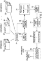
- Figure 3 illustrates a system and method for identifying one or more articulatable parts of a physical object using multiple 3D point clouds in accordance with various embodiments.
- the representative physical object is a laser printer 300. It is understood that the physical object can represent any 3D object that includes one or more articulatable parts, and that the laser printer 300 of Figure 3 is shown for non-limiting illustrative purposes.
- Configuration 1 shows the laser printer 300 prior to articulation of one or more articulatable parts.
- Configuration 2 shows the laser printer 300 after articulation of a first articulatable part, which is a pull-out paper tray 301 in Figure 3 .
- Configuration N shows the laser printer 300 after articulation of an N -th articulatable part, which is a pull-out envelop feed tray 302 in Figure 3 .
- the laser printer 300 typically includes several articulatable parts (e.g., toner cartridge drawer, paper tray, envelop feed tray, hinged communication port door, etc.), and that articulation of each of these parts can be represented by a different configuration of printer 300.
- a 3D sensor 304 is used to scan the printer 300 in each of its configurations 1- N .
- the 3D sensor 304 can be a commodity or commercial 3D scanner configured to be used with a smartphone or tablet computing device, examples of which are described hereinbelow.
- the 3D sensor 304 refers to a 3D scanning device in combination with a portable computing device.
- a user positions the 3D sensor 340 in proximity to the laser printer 300, and scans the laser printer 300 in each of its configurations 1- N.
- a first scan is generated by the 3D sensor 304 with the laser printer 300 in its non-articulated configuration (Configuration 1).
- the first scan results in the production of point cloud1, which is stored in a memory 310.
- the user pulls out the paper tray 301, which represents a first articulatable part of the laser printer 300 (Configuration 2).
- a second scan results in the production of point cloud2, which is stored in the memory 310.
- the user returns the paper tray 301 to its non-articulated position and pulls out the envelope feed tray 302, which represents a second articulatable part of the laser printer 300 (Configuration N ) .
- a third scan results in the production of point cloud M, which is stored in the memory 310.
- the 3D sensor 304 includes a mesh generator 306 and a point cloud generator 308.
- the mesh generator 306 is configured to generate a mesh as a result of each of the scans. Each mesh is composed of a set of vertices and a set of triangular faces formed by edges connecting the vertices.
- the point cloud generator 308 is configured to operate on each mesh produced by the mesh generator 306, and extracts a point cloud from each of the meshes. Each point cloud is composed of all the vertices of its corresponding mesh.
- the 3D sensor 304 includes the point cloud generator 308, but does not include the mesh generator 306. In such embodiments, the point cloud generator 308 is configured to generate a point cloud resulting from each scan.
- Point clouds 1 -M collected in the memory 310 are processed by an alignment module 312.
- the alignment module 312 is configured to perform a two-step alignment process, which involves coarse alignment followed by fine alignment of point cloud1 with point clouds2-M.
- An identification module 318 operates on the aligned point clouds 1- M to identify clusters of points belonging to each of the articulatable parts A 1 -A N 320 (e.g., paper tray 301, envelope feed tray 302). Having identified each of the articulatable parts A 1 -A N 320, subsequent processes can be performed, such as outputting and/or annotating 322 the articulatable parts A 1 -A N 320.
- a visual or graphical output can be produced, such as an approximate CAD model of the annotated laser printer 300 showing articulatable parts A 1 -A N 320 in annotated form (e.g., different colors, shading, hatching).
- a data structure or information signal can be generated as an output 322 for articulatable parts A 1 -A N 320, alone or in combination as the annotated laser printer 300.
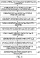
- Figure 4 is a flow diagram illustrating a computer-implemented method for identifying an articulatable part of a physical object using multiple 3D point clouds in accordance with various embodiments.
- the method shown in Figure 4 comprises obtaining 402 a first 3D point cloud (point cloud1) of a physical object in a non-articulated configuration.
- the method comprises obtaining a second 3D point cloud (point cloud2) of the physical object in an articulated configuration with at least one part articulated.
- the method also comprises downsampling 406 point cloud1 and point cloud2 to produce sparse point clouds 1 and 2.
- the method further comprises computing 408 Fast Point Feature Histogram (FPFH) descriptors from sparse point clouds 1 and 2.
- FPFH Fast Point Feature Histogram
- the method comprises coarsely aligning 410 point cloud1 and point cloud2 using the FPFH descriptors.
- the method also comprises finely aligning 412 point cloud1 and point cloud2 using ICP alignment. It is noted that downsampling 406 point cloud1 and point cloud2 is optional, and can be performed to increase processing speed.
- the method comprises finding 414 the nearest neighbors of points in point cloud1 to points in point cloud2.
- the method also comprises eliminating 416 the nearest neighbors of points in point cloud2, and applying 418 clustering to the remaining points in point cloud2.
- the method further involves distinguishing 420 the cluster of points associated with the articulatable part from noise point clusters.
- the distinguishing process 420 comprises receiving a user input that identifies the articulatable part, and distinguishing the cluster of points associated with the articulatable part from noise point clusters in response to the user input.
- the distinguishing process 420 comprises algorithmically (e.g., with no user input) distinguishing the cluster of points associated with the articulatable part from noise point clusters. The distinguishing process 420 results in identifying the articulatable part.
- the method comprises annotating 422 the cluster of points associated with the articulatable part, such as by coloring, shading, hatching, or otherwise graphically accentuating the articulatable part.
- the cluster of points associated with the articulatable part can have a color (or gray scale saturation) that is different from the color (or gray scale saturation) of the physical object.
- the method can comprise generating an output of the articulatable part, alone or in combination with the physical object, in the form of a graphical output (e.g., on a display), a data structure output (e.g., a data matrix), an information signal, or any combination of these outputs.
- Physical objects can be represented in 2D using images which are essentially pixel values (RGB for example) in a 2- dimensional grid with [X, Y] coordinates.
- Point clouds are a straightforward extension of this representation to 3D.
- a physical object can be represented by a set of pixel values whose locations are specified by [X, Y, Z] coordinates.
- Point clouds allow more variability in the structure of data being processed, unlike images which are always rectangular.
- Point clouds can also contain exact information about depth, while images are capable of only showing relative depth.
- point clouds are versatile and useful representations for understanding object articulation, which can be a modification in 3D of the object's pose.
- a commercial 3D scanner can be used with a smartphone or tablet device to scan a 3D object and generate multiple point clouds. If an object has k articulable parts, for example, k+1 point clouds are collected using the 3D scanner. In this case, one point cloud of the object with no articulation is collected, and k point clouds with each of the k parts articulated are collected, one at a time.
- the point cloud with no articulation defines the reference point cloud, which is referred to as point cloud1 for convenience.
- point cloud1 for convenience.
- point cloud1 For clarity of explanation, it is assumed that the 3D object has one articulatable part, it being understood that the 3D object may have any number of articulatable parts.
- the point cloud with one articulatable part is referred to as point cloud2 for convenience.
- point cloud2 it is assumed that the points are extremely close to the corresponding points in point cloud1, except for the region belonging to the articulatable part. With this assumption, a nearest neighbor elimination is performed. For example, if there exists a point [x, y, z] in point cloud1 within a neighborhood radius r of a point [x', y', z'] in point cloud1, then it is assumed that these points are both the same point with minor motion, and [x, y, z] does not belong to the articulatable part.
- point cloud1 and point cloud2 have to be precisely aligned. This is rarely the case with the noisy reconstruction obtained from 3D scanners.
- Automatic registration of point cloud1 and point cloud2 can be performed by downsampling point cloud1 and point cloud2, computing local descriptors, and finding correspondences based on a threshold criterion for matching.
- Figure 5A is an image showing point cloud1 (Pose 1), which serves as the reference point cloud of the laser printer 500 in its non-articulated configuration.
- Figure 5B is an image showing point cloud2 (Pose 2), which is the point cloud of the laser printer 500 in its articulated configuration.
- an opened front door 502 e.g., for accessing a toner cartridge
- Figure 5C is an image showing the superimposition of point cloud1 and point cloud2 (noting a change in the gray scale of point cloud1 and point cloud2 in the superimposition for convenience of explanation).
- Figure 5C shows unaligned point cloud1 and point cloud2.
- point cloud1 and point cloud2 are subject to a two-step alignment process.
- This two-step alignment process involves coarsely aligning point cloud1 and point cloud2 followed by finely aligning point cloud1 and point cloud2.
- Nearest neighbor elimination and subsequent processes can then be performed on the finely (e.g., precisely) aligned point cloud1 and point cloud2.
- point cloud1 and point cloud2 are downsampled with a voxel size of 0.05m, such that, along each dimension, one point is chosen in point cloud1 and point cloud2 for every 5cm. It is understood that the voxel size can be altered as needed or desired. Downsampling point cloud1 and point cloud2 produces sparse point cloud1 and sparse point cloud2. Fast Point Feature Histogram descriptors are computed on sparse point cloud1 and sparse point cloud2. Having computed the FPFH descriptors, the FPFH descriptors are matched across point cloud1 and point cloud2, and then used to align point cloud1 and point cloud2 by estimating a 3D transformation matrix on homogenous coordinates. This 3D transformation matrix is preferably a generalized 4x4 transformation matrix which can handle rotation, scaling, and translation.
- the parameters of the 3D transformation matrix are estimated by using a Random Sample Consensus (RANSAC) methodology (e.g., algorithm).
- RANSAC Random Sample Consensus
- the RANSAC methodology uses a sample consensus algorithm to find a set of parameters that yields the fewest outliers according to a specified distance criterion.
- the L2 norm of the transformed points and the reference points is chosen as the distance criterion. If the reference point and the transformed point have an L2 norm below a specified threshold (e.g., 2 mm), the transformed point is treated as an inlier, and otherwise as an outlier.
- a specified threshold e.g. 2 mm
- the estimated 3D transformation matrix is only a coarse global registration between point cloud1 and point cloud2.
- a process to finely align point cloud1 and point cloud2 is implemented.
- a local refinement is applied using an Iterative Closest Point (ICP) algorithm.
- ICP Iterative Closest Point
- the ICP algorithm assumes that nearby points are correspondences, and estimates a transform based on the nearby points.
- the transformation is then applied, and the correspondences are updated.
- the objective is once again to minimize the L2 norm between pairs of correspondences. This process is iteratively performed until convergence, such that the average L2 norm does not change between successive iterations.
- FIGS. 6A-6C are images that illustrate the two-step registration process described above.
- Figure 6A is an image showing unaligned point cloud1 and point cloud2.
- Figure 6B is an image showing coarse alignment of point cloud1 and point cloud2 resulting from RANSAC alignment.
- Figure 6C is an image showing fine (e.g., precise) alignment of point cloud1 and point cloud2 resulting from RANSAC and IPC alignment.
- each of point cloud1 and point cloud2 contains on the order of about 10 5 to 10 6 points in this representative embodiment, a naive nearest neighbor search cannot be performed as it will have a time complexity of O(N 2 ). Instead, an approximate nearest neighbor search is performed with an efficient data structure.
- each of point cloud1 and point cloud2 is represented as a k-d tree (k-dimensional tree). The construction of the k-d tree can be done in O(N log N) time complexity. Following this, for each point in cloud1, a check is made to determine if there exists a corresponding nearest neighbor in the tree of cloud2 (i.e., some point in cloud2 which is within a neighborhood radius of a point in cloud1).
- the worst case time complexity for the range search is O(kN(1-1/k)).
- k 3, which is the number of dimensions, so the search becomes O(N2/3) per point.
- the approximate nearest neighbor search over the entire point cloud becomes O(N4/3) (N points, O(N2/3) per point).
- Points are deleted from point cloud1 and point cloud2 (or, alternatively, point cloud2 only) if the search returns a neighbor. This deletion is O(log N) per point. Since this is an approximate search, it is not guaranteed to find all nearest neighbors, and due to the artifacts in the point clouds, there may be no nearest neighbors for certain points in the point clouds. As a result, eliminating points produces a messy (noisy) result.
- Figures 7A and 7B are images showing two views of superimposed point cloud1 and point cloud2 with a point deletion performed by eliminating points from point cloud2 with respect to point cloud1, and vice versa.
- the lighter gray points are remaining points of point cloud1 after point elimination
- the darker gray points are remaining points of point cloud2 after point elimination.
- clustering of point cloud1 and point cloud2 is performed after nearest neighbor elimination. For example, density-based spatial clustering of applications with noise (DBSCAN) can be performed on point cloud1 and point cloud2 after nearest neighbor elimination.
- DBSCAN density-based spatial clustering of applications with noise
- Figure 8A is an image showing original point cloud1, which corresponds to the non-articulated configuration of laser printer 500.
- Figure 8B is an image showing the articulatable part 502 rendered in place.
- Figure 8C is an image showing the clustering result, which includes numerous individual noise clusters 802 and a point cluster associated with the articulatable part 502 (e.g., the front door of the laser printer 500).
- Figure 8C shows the remaining point cloud2 corresponding to the articulatable part 502.
- the original point cloud1 (lighter gray scale) is annotated to include the remaining points of point cloud2 corresponding to the articulatable part 502, which can be articulated.
- Identifying the articulatable part 502 in the clustering result shown in Figure 8C involves distinguishing the cluster of points associated with the articulatable part 502 from noise point clusters 802.
- distinguishing the cluster of points associated with the articulatable part 502 from noise point clusters 802 involves input from a human annotator.
- the human annotator is asked during point cloud processing (e.g., step 420 in Figure 4 ) to mark a point 800 corresponding to the articulatable part 502 in original point cloud1 shown in Figure 8A .
- the point cluster in the clustering result shown in Figure 8B that point 800 belongs to is the set of points belonging to the articulatable part 502.
- identifying the articulatable part 502 in the clustering result shown in Figure 8B involves algorithmically distinguishing the cluster of points associated with the articulatable part 502 from noise point clusters 802. This approach does not involve or require input from a human annotator. Distinguishing the cluster of points associated with the articulatable part 502 from the noise point clusters 802 involves algorithmically determining a size of each of the clusters of points and selecting the largest point cluster as the cluster of points associated with the articulatable part 502.
- the processes described above can be performed on a physical object having a multiplicity of articulatable parts.
- the articulatable parts can be identified as described above using M 3D point clouds corresponding to N articulatable parts and a reference point cloud corresponding to the physical object prior to articulation of the articulatable parts.
- Figure 8D is an image showing point cloud1 corresponding to a laser printer 500 (non-articulated configuration) annotated with processed point clouds corresponding to four articulatable parts 502, 804, 806, 808 of the laser printer 500.
- the articulatable parts include the front door 502, a top cover 804, a front panel 806, and an envelope feed tray 808, each of which can be articulated.
- FIG. 9 is a block diagram of a system 900 configured to identify one or more articulatable parts of a physical object using multiple 3D point clouds in accordance with various embodiments.
- the system 900 is configured to implement the processes described hereinabove, including those illustrated in Figures 1-4 .
- the system 900 includes a computing device 902 communicatively coupled to a 3D sensor 904.
- the computing device 902 and the 3D sensor 904 are components of a unitary or common apparatus.
- the 3D sensor 904 is a component separate from the computing device 902, and is communicatively coupled to the computing device 902 via an input interface 908.
- the computing device 902 is representative of a variety of different computing devices including, for example, a smartphone, a tablet, a phablet, a laptop or other portable or desktop computer.
- the 3D sensor 904 is representative of a variety of different 3D scanning devices including, for example, an infrared or structured light 3D scanner, a 3D LIDAR scanner, a confocal or 3D laser scanner, a conoscopic holographic scanner, a modulated light 3D scanner, a time-of-flight 3D laser scanner, or a triangulation-based 3D laser scanner.
- the 3D sensor 904 can be a hand-held scanner or a tripod-supported 3D scanner.
- a suitable commodity 3D sensor 904 is the Structure Sensor for tablets and smartphones available from Occipital, Inc., San Francisco California.
- the computing device 902 includes a processor 906 coupled to the input interface 908 and an output interface 910.
- the input interface 908 and the output interface 910 can be configured as a wired interface or a wireless interface (e.g., a Bluetooth® or IEEE 802.11 compliant transceiver).
- the processor 906 can be representative of one or any combination of one or more multi-core processors, general purpose microprocessors, special purpose microprocessors, digital signal processors (DSPs), filters, and other digital logic circuitry (e.g., ASICs, FPGAs, ASSPs).
- the processor 906 is operatively coupled to memory 920, which may include one or more of ROM, RAM, SDRAM, NVRAM, EEPROM, and FLASH.
- the memory 920 is configured to store an operating system 922 comprising software that supports the basic functions of the computing device 902, such as scheduling tasks, executing applications, and controlling peripherals.
- the memory 920 is also configured to store code or instructions 924 in the form of software and/or firmware to be executed by the processor 906 for implementing the processes and algorithms described herein.
- the computing device 902 can include a graphical user interface (GUI) 930, which may include or take the form of a touchscreen.
- GUI graphical user interface
- the computing device 902 may include or be communicatively coupled to other user input devices, such as a pointing device 932 and/or a keyboard 934.
- the computing device 902 may be communicatively coupled to one or more output devices 940 via the output interface 910.
- the output devices 940 can include one or more of a display 942, a printer 944, a mass storage device 946, a portable storage device 948, and a communication channel 950.
- the input interface 908 is configured to receive a first 3D point cloud generated by the 3D sensor 904 associated with a physical object having at least one articulatable part.
- the first point cloud is associated with the physical object prior to articulation of the articulatable part.
- the input interface 908 is also configured to receive a second 3D point cloud generated by the 3D sensor 904 associated with the physical object after articulation of the articulatable part.
- the memory 920 is operably coupled to the input interface 908 and configured to store the first and second point clouds and program code 924.
- the processor 906 is operably coupled to the input interface 908, the output interface 910, and the memory 920.
- the program code 924 when executed by the processor 906, causes the processor 906 to align the first and second point clouds, find nearest neighbors of points in the first point cloud to points in the second point cloud, and eliminate the nearest neighbors of points in the second point cloud such that remaining points in the second point cloud comprise points associated with the articulatable part and points associated with noise.
- the program code 924 when executed by the processor 906, causes the processor 906 to generate an output comprising at least the remaining points of the second point cloud associated with the articulatable part without the noise points, and communicate the output to the output interface 910.
- the output can comprise one or more of a graphical output, a data structure output, and an information signal, which can be communicated from the output interface 910 to one or more of the output devices 940.
Landscapes
- Engineering & Computer Science (AREA)
- Theoretical Computer Science (AREA)
- Physics & Mathematics (AREA)
- General Physics & Mathematics (AREA)
- Computer Vision & Pattern Recognition (AREA)
- Software Systems (AREA)
- Computer Graphics (AREA)
- General Engineering & Computer Science (AREA)
- Multimedia (AREA)
- Artificial Intelligence (AREA)
- Evolutionary Computation (AREA)
- Data Mining & Analysis (AREA)
- Architecture (AREA)
- Geometry (AREA)
- Computer Hardware Design (AREA)
- General Health & Medical Sciences (AREA)
- Computing Systems (AREA)
- Databases & Information Systems (AREA)
- Health & Medical Sciences (AREA)
- Medical Informatics (AREA)
- Evolutionary Biology (AREA)
- Bioinformatics & Computational Biology (AREA)
- Bioinformatics & Cheminformatics (AREA)
- Life Sciences & Earth Sciences (AREA)
- Image Analysis (AREA)
- Image Generation (AREA)
Applications Claiming Priority (1)
| Application Number | Priority Date | Filing Date | Title |
|---|---|---|---|
| US16/235,434 US10896317B2 (en) | 2018-12-28 | 2018-12-28 | Apparatus and method for identifying an articulatable part of a physical object using multiple 3D point clouds |
Publications (2)
| Publication Number | Publication Date |
|---|---|
| EP3675040A1 EP3675040A1 (en) | 2020-07-01 |
| EP3675040B1 true EP3675040B1 (en) | 2021-08-11 |
Family
ID=69055788
Family Applications (1)
| Application Number | Title | Priority Date | Filing Date |
|---|---|---|---|
| EP19219916.4A Active EP3675040B1 (en) | 2018-12-28 | 2019-12-27 | Apparatus and method for identifying an articulatable part of a physical object using multiple 3d point clouds |
Country Status (3)
| Country | Link |
|---|---|
| US (2) | US10896317B2 (https=) |
| EP (1) | EP3675040B1 (https=) |
| JP (1) | JP7312685B2 (https=) |
Families Citing this family (11)
| Publication number | Priority date | Publication date | Assignee | Title |
|---|---|---|---|---|
| US11003959B1 (en) * | 2019-06-13 | 2021-05-11 | Amazon Technologies, Inc. | Vector norm algorithmic subsystems for improving clustering solutions |
| CN112907729B (zh) * | 2021-02-09 | 2022-02-11 | 南京航空航天大学 | 一种基于三维局部点云配准的复合材料预制体整体外形重建方法 |
| US11403817B1 (en) | 2021-04-14 | 2022-08-02 | Lineage Logistics, LLC | Point cloud filtering |
| US11725504B2 (en) * | 2021-05-24 | 2023-08-15 | Saudi Arabian Oil Company | Contactless real-time 3D mapping of surface equipment |
| CN115648197B (zh) * | 2021-07-09 | 2025-06-13 | 深圳富泰宏精密工业有限公司 | 零部件识别方法及系统 |
| US12437357B2 (en) * | 2021-12-23 | 2025-10-07 | United States Of America As Represented By The Secretary Of The Navy | Systems and methods to perform 3D localization of target objects in point cloud data using a corresponding 2D image |
| AU2023207962A1 (en) | 2022-01-11 | 2024-07-18 | Lineage Logistics, LLC | Planning and controlling automated layer pickers |
| CN114694134A (zh) * | 2022-03-23 | 2022-07-01 | 成都睿芯行科技有限公司 | 一种基于深度相机点云数据的托盘识别和定位方法 |
| CN119072716A (zh) | 2022-03-26 | 2024-12-03 | 美国亚德诺半导体公司 | 用于执行对象尺寸标注的方法和系统 |
| WO2023192137A1 (en) * | 2022-03-26 | 2023-10-05 | Analog Devices, Inc. | Methods and systems for performing object dimensioning |
| JP2024063579A (ja) * | 2022-10-26 | 2024-05-13 | 株式会社日立製作所 | 製造設備の設計支援装置並びに設計支援方法 |
Family Cites Families (12)
| Publication number | Priority date | Publication date | Assignee | Title |
|---|---|---|---|---|
| US7164789B2 (en) | 2003-08-11 | 2007-01-16 | Palo Alto Research Center Incorporated | Three-dimensional active vision with glyph address carpet |
| JP3966419B2 (ja) | 2004-12-15 | 2007-08-29 | 三菱電機株式会社 | 変化領域認識装置および変化認識システム |
| JP2007101197A (ja) | 2005-09-30 | 2007-04-19 | Nachi Fujikoshi Corp | 物体探索装置,物体探索装置を備えるロボットシステム及び物体探索方法 |
| US8452086B2 (en) | 2009-07-10 | 2013-05-28 | Palo Alto Research Center Incorporated | System and user interface for machine-assisted human labeling of pixels in an image |
| JP5753422B2 (ja) | 2011-03-28 | 2015-07-22 | 国立大学法人 熊本大学 | 3dパターンマッチング方法 |
| US9600711B2 (en) | 2012-08-29 | 2017-03-21 | Conduent Business Services, Llc | Method and system for automatically recognizing facial expressions via algorithmic periocular localization |
| US9154773B2 (en) | 2013-03-15 | 2015-10-06 | Seiko Epson Corporation | 2D/3D localization and pose estimation of harness cables using a configurable structure representation for robot operations |
| JP6230442B2 (ja) | 2014-02-20 | 2017-11-15 | 株式会社東芝 | 算出装置、方法及びプログラム |
| US9858640B1 (en) | 2015-07-15 | 2018-01-02 | Hrl Laboratories, Llc | Device and method for merging 3D point clouds from sparsely distributed viewpoints |
| WO2017096299A1 (en) * | 2015-12-04 | 2017-06-08 | Autodesk, Inc. | Keypoint-based point-pair-feature for scalable automatic global registration of large rgb-d scans |
| US10242282B2 (en) | 2017-03-20 | 2019-03-26 | Conduent Business Services, Llc | Video redaction method and system |
| US11308673B2 (en) * | 2018-05-03 | 2022-04-19 | Magic Leap, Inc. | Using three-dimensional scans of a physical subject to determine positions and/or orientations of skeletal joints in the rigging for a virtual character |
-
2018
- 2018-12-28 US US16/235,434 patent/US10896317B2/en active Active
-
2019
- 2019-12-09 JP JP2019221896A patent/JP7312685B2/ja active Active
- 2019-12-27 EP EP19219916.4A patent/EP3675040B1/en active Active
-
2021
- 2021-01-18 US US17/151,415 patent/US11610415B2/en active Active
Also Published As
| Publication number | Publication date |
|---|---|
| JP7312685B2 (ja) | 2023-07-21 |
| US20200210680A1 (en) | 2020-07-02 |
| US20210142039A1 (en) | 2021-05-13 |
| EP3675040A1 (en) | 2020-07-01 |
| US11610415B2 (en) | 2023-03-21 |
| JP2020109626A (ja) | 2020-07-16 |
| US10896317B2 (en) | 2021-01-19 |
Similar Documents
| Publication | Publication Date | Title |
|---|---|---|
| EP3675040B1 (en) | Apparatus and method for identifying an articulatable part of a physical object using multiple 3d point clouds | |
| US9412040B2 (en) | Method for extracting planes from 3D point cloud sensor data | |
| CN111328396B (zh) | 用于图像中的对象的姿态估计和模型检索 | |
| Bas et al. | Fitting a 3D morphable model to edges: A comparison between hard and soft correspondences | |
| CN108269266B (zh) | 使用马尔可夫随机场优化来产生分割图像 | |
| Riegler et al. | A deep primal-dual network for guided depth super-resolution | |
| US10026017B2 (en) | Scene labeling of RGB-D data with interactive option | |
| US9898858B2 (en) | Human body representation with non-rigid parts in an imaging system | |
| Rosman et al. | Patch‐collaborative spectral point‐cloud denoising | |
| JP6843237B2 (ja) | シーンのポイントクラウドを表現するシステム及び方法 | |
| AU2020200811A1 (en) | Direct meshing from multiview input using deep learning | |
| Tajdari et al. | Feature preserving non-rigid iterative weighted closest point and semi-curvature registration | |
| US20190362551A1 (en) | System and techniques for automated mesh retopology | |
| WO2016123913A1 (zh) | 数据处理的方法和装置 | |
| Maurer et al. | Combining shape from shading and stereo: A joint variational method for estimating depth, illumination and albedo | |
| Ozbay et al. | A hybrid method for skeleton extraction on Kinect sensor data: Combination of L1-Median and Laplacian shrinking algorithms | |
| CN115035224A (zh) | 图像处理和重构图像生成的方法和装置 | |
| Coleca et al. | Self-organizing maps for hand and full body tracking | |
| US20140168204A1 (en) | Model based video projection | |
| JP2019091436A (ja) | 3d配置のタイプに応じた2d画像の分類 | |
| CN116258830A (zh) | 用于3d建模的装置和方法 | |
| US11087536B2 (en) | Methods, devices and computer program products for generation of mesh in constructed 3D images | |
| WO2025071565A1 (en) | Three dimensional topology reconstruction with curvature-based and region growing segmentation of 3d scanning images | |
| Teng et al. | Reconstructing three-dimensional models of objects using a Kinect sensor | |
| CN115810081A (zh) | 三维模型生成方法及装置 |
Legal Events
| Date | Code | Title | Description |
|---|---|---|---|
| PUAI | Public reference made under article 153(3) epc to a published international application that has entered the european phase |
Free format text: ORIGINAL CODE: 0009012 |
|
| STAA | Information on the status of an ep patent application or granted ep patent |
Free format text: STATUS: THE APPLICATION HAS BEEN PUBLISHED |
|
| AK | Designated contracting states |
Kind code of ref document: A1 Designated state(s): AL AT BE BG CH CY CZ DE DK EE ES FI FR GB GR HR HU IE IS IT LI LT LU LV MC MK MT NL NO PL PT RO RS SE SI SK SM TR |
|
| AX | Request for extension of the european patent |
Extension state: BA ME |
|
| STAA | Information on the status of an ep patent application or granted ep patent |
Free format text: STATUS: REQUEST FOR EXAMINATION WAS MADE |
|
| 17P | Request for examination filed |
Effective date: 20210111 |
|
| RBV | Designated contracting states (corrected) |
Designated state(s): AL AT BE BG CH CY CZ DE DK EE ES FI FR GB GR HR HU IE IS IT LI LT LU LV MC MK MT NL NO PL PT RO RS SE SI SK SM TR |
|
| GRAP | Despatch of communication of intention to grant a patent |
Free format text: ORIGINAL CODE: EPIDOSNIGR1 |
|
| STAA | Information on the status of an ep patent application or granted ep patent |
Free format text: STATUS: GRANT OF PATENT IS INTENDED |
|
| INTG | Intention to grant announced |
Effective date: 20210316 |
|
| RAP3 | Party data changed (applicant data changed or rights of an application transferred) |
Owner name: PALO ALTO RESEARCH CENTER INCORPORATED |
|
| GRAS | Grant fee paid |
Free format text: ORIGINAL CODE: EPIDOSNIGR3 |
|
| GRAA | (expected) grant |
Free format text: ORIGINAL CODE: 0009210 |
|
| STAA | Information on the status of an ep patent application or granted ep patent |
Free format text: STATUS: THE PATENT HAS BEEN GRANTED |
|
| AK | Designated contracting states |
Kind code of ref document: B1 Designated state(s): AL AT BE BG CH CY CZ DE DK EE ES FI FR GB GR HR HU IE IS IT LI LT LU LV MC MK MT NL NO PL PT RO RS SE SI SK SM TR |
|
| REG | Reference to a national code |
Ref country code: CH Ref legal event code: EP |
|
| REG | Reference to a national code |
Ref country code: DE Ref legal event code: R096 Ref document number: 602019006816 Country of ref document: DE |
|
| REG | Reference to a national code |
Ref country code: IE Ref legal event code: FG4D Ref country code: AT Ref legal event code: REF Ref document number: 1420167 Country of ref document: AT Kind code of ref document: T Effective date: 20210915 |
|
| REG | Reference to a national code |
Ref country code: LT Ref legal event code: MG9D |
|
| REG | Reference to a national code |
Ref country code: NL Ref legal event code: MP Effective date: 20210811 |
|
| REG | Reference to a national code |
Ref country code: AT Ref legal event code: MK05 Ref document number: 1420167 Country of ref document: AT Kind code of ref document: T Effective date: 20210811 |
|
| PG25 | Lapsed in a contracting state [announced via postgrant information from national office to epo] |
Ref country code: ES Free format text: LAPSE BECAUSE OF FAILURE TO SUBMIT A TRANSLATION OF THE DESCRIPTION OR TO PAY THE FEE WITHIN THE PRESCRIBED TIME-LIMIT Effective date: 20210811 Ref country code: RS Free format text: LAPSE BECAUSE OF FAILURE TO SUBMIT A TRANSLATION OF THE DESCRIPTION OR TO PAY THE FEE WITHIN THE PRESCRIBED TIME-LIMIT Effective date: 20210811 Ref country code: SE Free format text: LAPSE BECAUSE OF FAILURE TO SUBMIT A TRANSLATION OF THE DESCRIPTION OR TO PAY THE FEE WITHIN THE PRESCRIBED TIME-LIMIT Effective date: 20210811 Ref country code: BG Free format text: LAPSE BECAUSE OF FAILURE TO SUBMIT A TRANSLATION OF THE DESCRIPTION OR TO PAY THE FEE WITHIN THE PRESCRIBED TIME-LIMIT Effective date: 20211111 Ref country code: AT Free format text: LAPSE BECAUSE OF FAILURE TO SUBMIT A TRANSLATION OF THE DESCRIPTION OR TO PAY THE FEE WITHIN THE PRESCRIBED TIME-LIMIT Effective date: 20210811 Ref country code: LT Free format text: LAPSE BECAUSE OF FAILURE TO SUBMIT A TRANSLATION OF THE DESCRIPTION OR TO PAY THE FEE WITHIN THE PRESCRIBED TIME-LIMIT Effective date: 20210811 Ref country code: NO Free format text: LAPSE BECAUSE OF FAILURE TO SUBMIT A TRANSLATION OF THE DESCRIPTION OR TO PAY THE FEE WITHIN THE PRESCRIBED TIME-LIMIT Effective date: 20211111 Ref country code: PT Free format text: LAPSE BECAUSE OF FAILURE TO SUBMIT A TRANSLATION OF THE DESCRIPTION OR TO PAY THE FEE WITHIN THE PRESCRIBED TIME-LIMIT Effective date: 20211213 Ref country code: FI Free format text: LAPSE BECAUSE OF FAILURE TO SUBMIT A TRANSLATION OF THE DESCRIPTION OR TO PAY THE FEE WITHIN THE PRESCRIBED TIME-LIMIT Effective date: 20210811 Ref country code: HR Free format text: LAPSE BECAUSE OF FAILURE TO SUBMIT A TRANSLATION OF THE DESCRIPTION OR TO PAY THE FEE WITHIN THE PRESCRIBED TIME-LIMIT Effective date: 20210811 |
|
| PG25 | Lapsed in a contracting state [announced via postgrant information from national office to epo] |
Ref country code: PL Free format text: LAPSE BECAUSE OF FAILURE TO SUBMIT A TRANSLATION OF THE DESCRIPTION OR TO PAY THE FEE WITHIN THE PRESCRIBED TIME-LIMIT Effective date: 20210811 Ref country code: LV Free format text: LAPSE BECAUSE OF FAILURE TO SUBMIT A TRANSLATION OF THE DESCRIPTION OR TO PAY THE FEE WITHIN THE PRESCRIBED TIME-LIMIT Effective date: 20210811 Ref country code: GR Free format text: LAPSE BECAUSE OF FAILURE TO SUBMIT A TRANSLATION OF THE DESCRIPTION OR TO PAY THE FEE WITHIN THE PRESCRIBED TIME-LIMIT Effective date: 20211112 |
|
| PG25 | Lapsed in a contracting state [announced via postgrant information from national office to epo] |
Ref country code: NL Free format text: LAPSE BECAUSE OF FAILURE TO SUBMIT A TRANSLATION OF THE DESCRIPTION OR TO PAY THE FEE WITHIN THE PRESCRIBED TIME-LIMIT Effective date: 20210811 |
|
| PG25 | Lapsed in a contracting state [announced via postgrant information from national office to epo] |
Ref country code: DK Free format text: LAPSE BECAUSE OF FAILURE TO SUBMIT A TRANSLATION OF THE DESCRIPTION OR TO PAY THE FEE WITHIN THE PRESCRIBED TIME-LIMIT Effective date: 20210811 |
|
| REG | Reference to a national code |
Ref country code: DE Ref legal event code: R097 Ref document number: 602019006816 Country of ref document: DE |
|
| PG25 | Lapsed in a contracting state [announced via postgrant information from national office to epo] |
Ref country code: SM Free format text: LAPSE BECAUSE OF FAILURE TO SUBMIT A TRANSLATION OF THE DESCRIPTION OR TO PAY THE FEE WITHIN THE PRESCRIBED TIME-LIMIT Effective date: 20210811 Ref country code: SK Free format text: LAPSE BECAUSE OF FAILURE TO SUBMIT A TRANSLATION OF THE DESCRIPTION OR TO PAY THE FEE WITHIN THE PRESCRIBED TIME-LIMIT Effective date: 20210811 Ref country code: RO Free format text: LAPSE BECAUSE OF FAILURE TO SUBMIT A TRANSLATION OF THE DESCRIPTION OR TO PAY THE FEE WITHIN THE PRESCRIBED TIME-LIMIT Effective date: 20210811 Ref country code: EE Free format text: LAPSE BECAUSE OF FAILURE TO SUBMIT A TRANSLATION OF THE DESCRIPTION OR TO PAY THE FEE WITHIN THE PRESCRIBED TIME-LIMIT Effective date: 20210811 Ref country code: CZ Free format text: LAPSE BECAUSE OF FAILURE TO SUBMIT A TRANSLATION OF THE DESCRIPTION OR TO PAY THE FEE WITHIN THE PRESCRIBED TIME-LIMIT Effective date: 20210811 Ref country code: AL Free format text: LAPSE BECAUSE OF FAILURE TO SUBMIT A TRANSLATION OF THE DESCRIPTION OR TO PAY THE FEE WITHIN THE PRESCRIBED TIME-LIMIT Effective date: 20210811 |
|
| PLBE | No opposition filed within time limit |
Free format text: ORIGINAL CODE: 0009261 |
|
| STAA | Information on the status of an ep patent application or granted ep patent |
Free format text: STATUS: NO OPPOSITION FILED WITHIN TIME LIMIT |
|
| 26N | No opposition filed |
Effective date: 20220512 |
|
| PG25 | Lapsed in a contracting state [announced via postgrant information from national office to epo] |
Ref country code: MC Free format text: LAPSE BECAUSE OF FAILURE TO SUBMIT A TRANSLATION OF THE DESCRIPTION OR TO PAY THE FEE WITHIN THE PRESCRIBED TIME-LIMIT Effective date: 20210811 Ref country code: IT Free format text: LAPSE BECAUSE OF FAILURE TO SUBMIT A TRANSLATION OF THE DESCRIPTION OR TO PAY THE FEE WITHIN THE PRESCRIBED TIME-LIMIT Effective date: 20210811 |
|
| PG25 | Lapsed in a contracting state [announced via postgrant information from national office to epo] |
Ref country code: SI Free format text: LAPSE BECAUSE OF FAILURE TO SUBMIT A TRANSLATION OF THE DESCRIPTION OR TO PAY THE FEE WITHIN THE PRESCRIBED TIME-LIMIT Effective date: 20210811 |
|
| REG | Reference to a national code |
Ref country code: BE Ref legal event code: MM Effective date: 20211231 |
|
| PG25 | Lapsed in a contracting state [announced via postgrant information from national office to epo] |
Ref country code: LU Free format text: LAPSE BECAUSE OF NON-PAYMENT OF DUE FEES Effective date: 20211227 Ref country code: IE Free format text: LAPSE BECAUSE OF NON-PAYMENT OF DUE FEES Effective date: 20211227 |
|
| PG25 | Lapsed in a contracting state [announced via postgrant information from national office to epo] |
Ref country code: BE Free format text: LAPSE BECAUSE OF NON-PAYMENT OF DUE FEES Effective date: 20211231 |
|
| PG25 | Lapsed in a contracting state [announced via postgrant information from national office to epo] |
Ref country code: CY Free format text: LAPSE BECAUSE OF FAILURE TO SUBMIT A TRANSLATION OF THE DESCRIPTION OR TO PAY THE FEE WITHIN THE PRESCRIBED TIME-LIMIT Effective date: 20210811 |
|
| PG25 | Lapsed in a contracting state [announced via postgrant information from national office to epo] |
Ref country code: HU Free format text: LAPSE BECAUSE OF FAILURE TO SUBMIT A TRANSLATION OF THE DESCRIPTION OR TO PAY THE FEE WITHIN THE PRESCRIBED TIME-LIMIT; INVALID AB INITIO Effective date: 20191227 |
|
| REG | Reference to a national code |
Ref country code: CH Ref legal event code: PL |
|
| PG25 | Lapsed in a contracting state [announced via postgrant information from national office to epo] |
Ref country code: LI Free format text: LAPSE BECAUSE OF NON-PAYMENT OF DUE FEES Effective date: 20221231 Ref country code: CH Free format text: LAPSE BECAUSE OF NON-PAYMENT OF DUE FEES Effective date: 20221231 |
|
| PG25 | Lapsed in a contracting state [announced via postgrant information from national office to epo] |
Ref country code: MK Free format text: LAPSE BECAUSE OF FAILURE TO SUBMIT A TRANSLATION OF THE DESCRIPTION OR TO PAY THE FEE WITHIN THE PRESCRIBED TIME-LIMIT Effective date: 20210811 |
|
| PG25 | Lapsed in a contracting state [announced via postgrant information from national office to epo] |
Ref country code: MT Free format text: LAPSE BECAUSE OF FAILURE TO SUBMIT A TRANSLATION OF THE DESCRIPTION OR TO PAY THE FEE WITHIN THE PRESCRIBED TIME-LIMIT Effective date: 20210811 |
|
| PG25 | Lapsed in a contracting state [announced via postgrant information from national office to epo] |
Ref country code: TR Free format text: LAPSE BECAUSE OF FAILURE TO SUBMIT A TRANSLATION OF THE DESCRIPTION OR TO PAY THE FEE WITHIN THE PRESCRIBED TIME-LIMIT Effective date: 20210811 |
|
| PGFP | Annual fee paid to national office [announced via postgrant information from national office to epo] |
Ref country code: DE Payment date: 20251126 Year of fee payment: 7 |
|
| PGFP | Annual fee paid to national office [announced via postgrant information from national office to epo] |
Ref country code: GB Payment date: 20251119 Year of fee payment: 7 |
|
| PGFP | Annual fee paid to national office [announced via postgrant information from national office to epo] |
Ref country code: FR Payment date: 20251120 Year of fee payment: 7 |