EP3674988A1 - Method and system for prediction of correct discrete sensor data based on temporal uncertainty - Google Patents
Method and system for prediction of correct discrete sensor data based on temporal uncertainty Download PDFInfo
- Publication number
- EP3674988A1 EP3674988A1 EP19219844.8A EP19219844A EP3674988A1 EP 3674988 A1 EP3674988 A1 EP 3674988A1 EP 19219844 A EP19219844 A EP 19219844A EP 3674988 A1 EP3674988 A1 EP 3674988A1
- Authority
- EP
- European Patent Office
- Prior art keywords
- sensor data
- discrete
- continuous
- discrete sensor
- pseudo
- Prior art date
- Legal status (The legal status is an assumption and is not a legal conclusion. Google has not performed a legal analysis and makes no representation as to the accuracy of the status listed.)
- Withdrawn
Links
Images


Classifications
-
- G—PHYSICS
- G06—COMPUTING OR CALCULATING; COUNTING
- G06F—ELECTRIC DIGITAL DATA PROCESSING
- G06F11/00—Error detection; Error correction; Monitoring
- G06F11/07—Responding to the occurrence of a fault, e.g. fault tolerance
- G06F11/0703—Error or fault processing not based on redundancy, i.e. by taking additional measures to deal with the error or fault not making use of redundancy in operation, in hardware, or in data representation
- G06F11/0706—Error or fault processing not based on redundancy, i.e. by taking additional measures to deal with the error or fault not making use of redundancy in operation, in hardware, or in data representation the processing taking place on a specific hardware platform or in a specific software environment
- G06F11/0745—Error or fault processing not based on redundancy, i.e. by taking additional measures to deal with the error or fault not making use of redundancy in operation, in hardware, or in data representation the processing taking place on a specific hardware platform or in a specific software environment in an input/output transactions management context
-
- G—PHYSICS
- G06—COMPUTING OR CALCULATING; COUNTING
- G06N—COMPUTING ARRANGEMENTS BASED ON SPECIFIC COMPUTATIONAL MODELS
- G06N3/00—Computing arrangements based on biological models
- G06N3/02—Neural networks
- G06N3/08—Learning methods
-
- G—PHYSICS
- G05—CONTROLLING; REGULATING
- G05B—CONTROL OR REGULATING SYSTEMS IN GENERAL; FUNCTIONAL ELEMENTS OF SUCH SYSTEMS; MONITORING OR TESTING ARRANGEMENTS FOR SUCH SYSTEMS OR ELEMENTS
- G05B23/00—Testing or monitoring of control systems or parts thereof
- G05B23/02—Electric testing or monitoring
- G05B23/0205—Electric testing or monitoring by means of a monitoring system capable of detecting and responding to faults
- G05B23/0218—Electric testing or monitoring by means of a monitoring system capable of detecting and responding to faults characterised by the fault detection method dealing with either existing or incipient faults
- G05B23/0221—Preprocessing measurements, e.g. data collection rate adjustment; Standardization of measurements; Time series or signal analysis, e.g. frequency analysis or wavelets; Trustworthiness of measurements; Indexes therefor; Measurements using easily measured parameters to estimate parameters difficult to measure; Virtual sensor creation; De-noising; Sensor fusion; Unconventional preprocessing inherently present in specific fault detection methods like PCA-based methods
-
- G—PHYSICS
- G06—COMPUTING OR CALCULATING; COUNTING
- G06F—ELECTRIC DIGITAL DATA PROCESSING
- G06F11/00—Error detection; Error correction; Monitoring
- G06F11/07—Responding to the occurrence of a fault, e.g. fault tolerance
- G06F11/0703—Error or fault processing not based on redundancy, i.e. by taking additional measures to deal with the error or fault not making use of redundancy in operation, in hardware, or in data representation
- G06F11/0793—Remedial or corrective actions
-
- G—PHYSICS
- G06—COMPUTING OR CALCULATING; COUNTING
- G06N—COMPUTING ARRANGEMENTS BASED ON SPECIFIC COMPUTATIONAL MODELS
- G06N3/00—Computing arrangements based on biological models
- G06N3/02—Neural networks
-
- G—PHYSICS
- G06—COMPUTING OR CALCULATING; COUNTING
- G06N—COMPUTING ARRANGEMENTS BASED ON SPECIFIC COMPUTATIONAL MODELS
- G06N3/00—Computing arrangements based on biological models
- G06N3/02—Neural networks
- G06N3/04—Architecture, e.g. interconnection topology
- G06N3/044—Recurrent networks, e.g. Hopfield networks
-
- G—PHYSICS
- G06—COMPUTING OR CALCULATING; COUNTING
- G06N—COMPUTING ARRANGEMENTS BASED ON SPECIFIC COMPUTATIONAL MODELS
- G06N3/00—Computing arrangements based on biological models
- G06N3/02—Neural networks
- G06N3/04—Architecture, e.g. interconnection topology
- G06N3/044—Recurrent networks, e.g. Hopfield networks
- G06N3/0442—Recurrent networks, e.g. Hopfield networks characterised by memory or gating, e.g. long short-term memory [LSTM] or gated recurrent units [GRU]
-
- G—PHYSICS
- G06—COMPUTING OR CALCULATING; COUNTING
- G06N—COMPUTING ARRANGEMENTS BASED ON SPECIFIC COMPUTATIONAL MODELS
- G06N3/00—Computing arrangements based on biological models
- G06N3/02—Neural networks
- G06N3/08—Learning methods
- G06N3/09—Supervised learning
Definitions
- the disclosure herein generally relates to field of prediction of correct discrete sensor data and, more particularly, to a method and a system for prediction of correct discrete sensor data based on temporal uncertainty.
- sensors are an important source of real time data for various applications across different domains, such as smart environment, assistance systems, robotics, environmental motoring and human activity recognition and so on.
- the main purpose of sensors is to collect data from the surrounding environment, which is further processed and analyzed for various applications.
- Sensor networks and their systems can fail due to multiple reasons including intrusion attacks, node failures, and link failures and so on.
- the sensor failure leads to missing or corrupt data collection by sensors systems wherein corrupt or missing data can cause prediction inaccuracies or problems in continuous events processing process, which results in complete failure of a system.
- forecasting or estimation techniques are used for enabling a continuous flow of data even when the sensor fails temporarily.
- Forecasting or estimation techniques such as time-series prediction has been used for both forecasting as well as filling in missing data.
- the discrete sensor data is sparse and largely unbalanced, wherein most of the time the sensor data is 'No' and comparatively only a few samples of 'Yes' is available.
- the predicted/forecasted sensor data would be 'No'.
- mere usage of neural network based techniques such as Recurrent Neural Networks (RNN) or Long Short-Term Memory (LSTM) technique based deep model may not predict or forecast accurately.
- RNN Recurrent Neural Networks
- LSTM Long Short-Term Memory
- Embodiments of the present disclosure present technological improvements as solutions to one or more of the above-mentioned technical problems recognized by the inventors in conventional systems.
- a method and system for prediction of correct discrete sensor data is provided, enabling continuous flow of data even when a discrete sensor fails.
- the collected discrete sensor data is usually sparse and largely unbalanced, wherein most of the discrete sensor data is 'No' or '0' and comparatively only a few samples of 'Yes' or '1', hence making prediction very challenging.
- the proposed prediction techniques based on introduction of temporal uncertainty is performed in several stages which includes pre-processing of received discrete sensor data, introduction of temporal uncertainty techniques followed by prediction based on neural network techniques of learning pattern using historical data.
- a method for prediction of correct discrete sensor data based on temporal uncertainty includes receiving discrete sensor data relating to a human using a plurality of sensors, wherein the discrete sensor data that is received using plurality of discrete sensors indicates activities relating to the human for a specific time interval. Further the method includes identifying a corrupt discrete sensor data in the received discrete sensor data, wherein the corrupt discrete sensor data is identified by a sensor status parameter. Furthermore the method includes converting the identified corrupt discrete sensor data in to a pseudo-continuous sensor data, wherein the identified corrupt discrete sensor data is converted in to the pseudo-continuous sensor data by assigning a random value from a pre-defined range individually for positive and negative discrete sensor data.
- the method includes introducing the temporal uncertainty in to the pseudo-continuous sensor data, wherein temporal uncertainty is introduced in to the pseudo-continuous sensor data by replacing the pseudo-continuous sensor data by a random value from a pre-defined range. Furthermore the method includes substituting the temporal uncertainty introduced pseudo-continuous sensor data with a correct sensor data using a Long Short-Term Memory (LSTM) technique to predict a corrected continuous sensor data, wherein corrected continuous sensor data is predicted based on a learning pattern and historical data stored in a database. Finally the method includes reconverting the corrected continuous sensor data to corrected discrete sensor data, wherein the corrected continuous sensor data is re-converted back to its original discrete format by replacing corrected continuous sensor data by pre-defined binary values.
- LSTM Long Short-Term Memory
- a system for prediction of correct discrete sensor data based on temporal uncertainty comprises a memory storing instructions and a centralized database, one or more communication interfaces; and one or more hardware processors coupled to the memory via the one or more communication interfaces, wherein the one or more hardware processors are configured by instructions to a pre-processor for receiving the discrete sensor data relating to a human using a plurality of sensors and identifying a corrupt discrete sensor data in the received discrete sensor data. Further the system comprises a converter converting the identified corrupt discrete sensor data in to a pseudo-continuous sensor data.
- the system comprises a processor introducing the temporal uncertainty in to the pseudo-continuous sensor data; a correct data predictor substituting the temporal uncertainty introduced pseudo-continuous sensor data with a correct sensor data using a Long Short-Term Memory (LSTM) technique to predict a corrected continuous sensor data.
- LSTM Long Short-Term Memory
- the system comprises and a re-converter for reconverting the corrected continuous sensor data to corrected discrete sensor data.
- a non-transitory computer readable medium for prediction of correct discrete sensor data based on temporal uncertainty.
- the program includes receiving discrete sensor data relating to a human using a plurality of sensors, wherein the discrete sensor data that is received using plurality of discrete sensors indicates activities relating to the human for a specific time interval. Further the program includes identifying a corrupt discrete sensor data in the received discrete sensor data, wherein the corrupt discrete sensor data is identified by a sensor status parameter. Furthermore the program includes converting the identified corrupt discrete sensor data in to a pseudo-continuous sensor data, wherein the identified corrupt discrete sensor data is converted in to the pseudo-continuous sensor data by assigning a random value from a pre-defined range individually for positive and negative discrete sensor data.
- the program includes introducing the temporal uncertainty in to the pseudo-continuous sensor data, wherein temporal uncertainty is introduced in to the pseudo-continuous sensor data by replacing the pseudo-continuous sensor data by a random value from a pre-defined range. Furthermore the program includes substituting the temporal uncertainty introduced pseudo-continuous sensor data with a correct sensor data using a Long Short-Term Memory (LSTM) technique to predict a corrected continuous sensor data, wherein corrected continuous sensor data is predicted based on a learning pattern and historical data stored in a database. Finally the program includes reconverting the corrected continuous sensor data to corrected discrete sensor data, wherein the corrected continuous sensor data is re-converted back to its original discrete format by replacing corrected continuous sensor data by pre-defined binary values.
- LSTM Long Short-Term Memory
- FIG. 1 through FIG.8 where similar reference characters denote corresponding features consistently throughout the figures, there are shown preferred embodiments and these embodiments are described in the context of the following exemplary system and/or method.
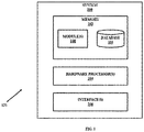
- FIG. 1 illustrates an exemplary block diagram of a system 100 for authenticating humans based on behavioral pattern according to an embodiment of the present disclosure.
- the system 100 includes one or more processors 104, communication interface device(s) or input/output (I/O) interface(s) 106, and one or more data storage devices or memory 102 operatively coupled to the one or more processors 104.
- the memory 102 comprises one or more modules 108 and the database 110.
- the one or more processors 104 that are hardware processors can be implemented as one or more microprocessors, microcomputers, microcontrollers, digital signal processors, central processing units, state machines, logic circuitries, and/or any devices that manipulate signals based on operational instructions.
- the processor(s) is configured to fetch and execute computer-readable instructions stored in the memory.
- the system 100 can be implemented in a variety of computing systems, such as laptop computers, notebooks, hand-held devices, workstations, mainframe computers, servers, a network cloud and the like.
- the I/O interface device(s) 106 can include a variety of software and hardware interfaces, for example, a web interface, a graphical subject interface, and the like and can facilitate multiple communications within a wide variety of networks N/W and protocol types, including wired networks, for example, LAN, cable, etc., and wireless networks, such as WLAN, cellular, or satellite.
- the I/O interface device(s) can include one or more ports for connecting a number of devices to one another or to another server.
- the memory 102 may include any computer-readable medium known in the art including, for example, volatile memory, such as static random access memory (SRAM) and dynamic random access memory (DRAM), and/or non-volatile memory, such as read only memory (ROM), erasable programmable ROM, flash memories, hard disks, optical disks, and magnetic tapes.
- volatile memory such as static random access memory (SRAM) and dynamic random access memory (DRAM)
- DRAM dynamic random access memory
- non-volatile memory such as read only memory (ROM), erasable programmable ROM, flash memories, hard disks, optical disks, and magnetic tapes.
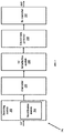
- FIG. 2 is a block diagram of various modules 108 stored in the memory 102 of the system 100 of FIG. 1 in accordance with an embodiment of the present disclosure.
- the modules 108 include a receiving module 202 which further includes an identification module 204, a convertor 206, a TU introduction module 208, a correct data predictor 210 and a re-convertor 212 that are implemented as at least one of a logically self-contained part of a software program, a self-contained hardware component, and/or, a self-contained hardware component with a logically self-contained part of a software program embedded into each of the hardware component that when executed perform the above method described herein.
- the system 200 comprises the receiving module 202 that is configured for receiving discrete sensor data using a plurality of sensors from a human.
- the receiving module 202 further comprises of the identification module 204 that is configured for identifying a corrupt discrete sensor data in the received discrete sensor data.
- the received discrete sensor data indicates Activities of Daily Living (ADL) pertaining to a subject for a specific time interval from a smart environment.
- ADL Activities of Daily Living
- a plurality discrete sensors are embedded in a smart environment such as an old age home, orphanage or home and so on.
- the plurality of sensors used are discrete/binary (such as pressure switches, temperature switches, thru-beam photoelectric sensors, proximity sensors, push buttons and so on) sensors which are unobtrusive and non-intrusive .
- the plurality of discrete sensors continuously monitor routine activities of subjects housed in the smart environment.
- the plurality of discrete sensors are connected to a variety of network devices, including routers, bridges, servers, computing devices, storage devices.
- discrete sensor data comprises parameters such as sensor replication, sensor status, sensor position, remaining battery life (used to power up the sensor), current date and time as illustrated below in table 1: Table 1 Date Time Sensor status Sensor replication Location of sensor Sensor type 2018:12:01 00:00:37 OK 1 door PIR 2018:12:01 00:00:37 NOK 0 bed Vibration 2018:12:01 00:00:37 OK 23 Bedroom temperature 2018:12:01 00:00:37 OK 0 kitchen PIR Discrete Sensor Data
- discrete sensor data indicates ADL pertaining to a human for a specific time interval from a smart environment.
- the ADL activities may not be received at all times due to failure or faulty sensors that may be caused due to various reasons that include battery drain, communication outage, malfunctioning.
- the received discrete sensor data contains both correct and corrupt discrete sensor data, wherein the corrupt discrete sensor data refers to gaps in the received discrete sensor data that caused due to sensor failure. Further one of the parameters of the discrete sensor enables to identify corrupt discrete sensor data.
- a 'sensor status' parameter enables identification of corrupt discrete sensor data wherein, the sensor status parameter reflects 'NOK' during a sensor failure and the sensor status is reflects "OK", when the sensor is receiving sensor data.
- the sensor status parameter reflects 'NOK' during a sensor failure and the sensor status is reflects "OK", when the sensor is receiving sensor data.
- the system 200 further comprises the convertor 206 that is configured for converting the identified corrupt discrete sensor data in to a pseudo-continuous sensor data.
- the identified corrupt discrete sensor data is converted in to the pseudo-continuous sensor data by assigning a random value, from a pre-defined range individually for positive and negative discrete sensor data. Further the random value is assigned based on well-known random sampling techniques.
- positive discrete sensor data may be represented by 'Yes' or '0' and negative discrete sensor data may be represented by 'Yes' or '0'.
- the identified corrupt discrete sensor data is converted to pseudo-continuous and finally represented in form of an array which represents pseudo-continuous sensor data.
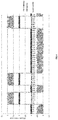
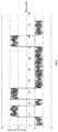
- FIG.4 illustrates graphs of pseudo-continuous sensor data, which was converted from corrupt discrete sensor data, where X-Axis represents sample number of the discrete sensor data and Y-Axis represents corresponding discrete sensor value.
- the system 200 further comprises the TU introduction module 208 that is configured for introducing the temporal uncertainty in to the pseudo-continuous sensor data.
- the temporal uncertainty is introduced in to the pseudo-continuous sensor data by replacing the pseudo-continuous sensor data by a random value from a pre-defined range.
- the temporal uncertainty is introduced in to the pseudo-continuous sensor data is represented by parameter 'dataArray', where index represents the index of the dataArray , as shown below;
- FIG.5 illustrates graphs of pseudo-continuous sensor data, which has been introduced with temporal uncertainty, where X-Axis represents sample number of the discrete sensor data and Y-Axis represents corresponding discrete sensor value.
- the system 200 further comprises the correct data predictor 210 that is configured for substituting the temporal uncertainty introduced pseudo-continuous sensor data with a correct sensor data using a Long Short-Term Memory (LSTM) technique to predict a corrected continuous sensor data.
- the corrected continuous sensor data is predicted using LSTM based on a learning pattern and historical data stored in a database 110.
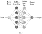
- the proposed LSTM network is designed as illustrated in FIG 6 , wherein a data batch for one week at a time for each sensor. Hence for each sensor, a batch size of 40320 is used for every 15 seconds.
- the proposed LSTM network type is a stateful LSTM network, with one input layer, and two hidden layers of dimension 50 each, each 10 neurons are symbolized as one in network architecture for space constraint. Further number of epochs used is 200, and the loss function is based on RMSE (Root Mean Squared Error) as time-series is predicted or forecasting.
- RMSE Root Mean Squared Error
- the system 200 further comprises the re-convertor 212 that is configured for reconverting the corrected continuous sensor data to corrected discrete sensor data.
- the corrected continuous sensor data is re-converted back to its original discrete format by replacing corrected continuous sensor data by pre-defined binary values.
- corrected continuous sensor data represented using parameter 'resultArray' and index is the index of the resultArray
- corrected continuous sensor data is re-converted back to its original format of corrected discrete sensor data by replacing corrected continuous sensor data by pre-defined binary values , such as positive corrected continuous sensor data is replaced by a pre-defined binary values of 1 and negative corrected continuous sensor data is replaced by a pre-defined binary values of 0 as shown below;
- corrected continuous sensor data is reconverted back to its original format of discrete data and displayed as corrected discrete sensor data.
- FIG.7 illustrates graphs of corrected discrete sensor data, which has been introduced with temporal uncertainty, where X-Axis represents sample number of the discrete sensor data and Y-Axis represents corresponding discrete sensor value.
- FIG.8 illustrates predicted and expected graphs of corrected continuous sensor data sensor value using Long Short-Term Memory (LSTM) techniques, where X-Axis represents sample number of the discrete sensor data and Y-Axis represents corresponding time in seconds.
- LSTM Long Short-Term Memory
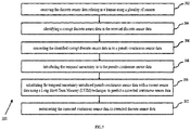
- FIG. 3 is an exemplary flow diagram illustrating a method for prediction of correct discrete sensor data based on temporal uncertainty using the system 100 of FIG. 1 according to an embodiment of the present disclosure.
- the system 100 comprises one or more data storage devices or the memory 102 operatively coupled to the one or more hardware processors 104 and is configured to store instructions for execution of steps of the method by the one or more processors 104.
- the steps of the method of the present disclosure will now be explained with reference to the components of the system 100 and the modules 202-212 as depicted in FIGS. 1-2 , and the flow diagram as depicted in FIG.3 .
- receiving the discrete sensor data relating to a human using a plurality of sensors is received by the receiving module 202.
- the discrete sensor data that is received using plurality of discrete sensors indicates activities of daily living (ADL) relating to the human for a specific time interval.
- ADL daily living
- a corrupt discrete sensor data is identified in the received discrete sensor data based on a 'sensor status' parameter obtained from the received sensor data.
- the identified corrupt discrete sensor data is converted to a pseudo-continuous sensor data, wherein the identified corrupt discrete sensor data is converted in to the pseudo-continuous sensor data by assigning a random value from a pre-defined range individually for positive and negative discrete sensor data.
- temporal uncertainty is introduced in to the pseudo-continuous sensor data, by replacing the pseudo-continuous sensor data by a random value from a pre-defined range.
- the temporal uncertainty introduced pseudo-continuous sensor data is substituting with a correct sensor data using a Long Short-Term Memory (LSTM) technique to predict a corrected continuous sensor data based on a learning pattern and historical data stored in a database.
- LSTM Long Short-Term Memory
- the corrected continuous sensor data is reconverted to corrected discrete sensor data, wherein the corrected continuous sensor data is re-converted back to its original discrete format by replacing corrected continuous sensor data by pre-defined binary values.
- the proposed method and system for prediction of correct discrete sensor data enables continuous flow of data even when a discrete sensor fails.
- the collected discrete sensor data is usually sparse and largely unbalanced, wherein most of the discrete sensor data is 'No' or '0' and comparatively only a few samples of 'Yes' or '1', hence making prediction very challenging.
- the proposed prediction techniques based on introduction of temporal uncertainty is performed in several stages which includes pre-processing of received discrete sensor data, introduction of temporal uncertainty techniques followed by prediction based on neural network techniques of learning pattern using historical data.
- the hardware device can be any kind of device which can be programmed including e.g. any kind of computer like a server or a personal computer, or the like, or any combination thereof.
- the device may also include means which could be e.g. hardware means like e.g. an application-specific integrated circuit (ASIC), a field-programmable gate array (FPGA), or a combination of hardware and software means, e.g.
- ASIC application-specific integrated circuit
- FPGA field-programmable gate array
- the means can include both hardware means and software means.
- the method embodiments described herein could be implemented in hardware and software.
- the device may also include software means.
- the embodiments may be implemented on different hardware devices, e.g. using a plurality of CPUs.
- the embodiments herein can comprise hardware and software elements.
- the embodiments that are implemented in software include but are not limited to, firmware, resident software, microcode, etc.
- the functions performed by various modules described herein may be implemented in other modules or combinations of other modules.
- a computer-usable or computer readable medium can be any apparatus that can comprise, store, communicate, propagate, or transport the program for use by or in connection with the instruction execution system, apparatus, or device.
- a computer-readable storage medium refers to any type of physical memory on which information or data readable by a processor may be stored.
- a computer-readable storage medium may store instructions for execution by one or more processors, including instructions for causing the processor(s) to perform steps or stages consistent with the embodiments described herein.
- the term "computer-readable medium” should be understood to include tangible items and exclude carrier waves and transient signals, i.e., be non-transitory. Examples include random access memory (RAM), read-only memory (ROM), volatile memory, nonvolatile memory, hard drives, CD ROMs, DVDs, flash drives, disks, and any other known physical storage media.
Landscapes
- Engineering & Computer Science (AREA)
- Theoretical Computer Science (AREA)
- Physics & Mathematics (AREA)
- General Physics & Mathematics (AREA)
- General Engineering & Computer Science (AREA)
- General Health & Medical Sciences (AREA)
- Computing Systems (AREA)
- Computational Linguistics (AREA)
- Data Mining & Analysis (AREA)
- Evolutionary Computation (AREA)
- Biomedical Technology (AREA)
- Molecular Biology (AREA)
- Biophysics (AREA)
- Artificial Intelligence (AREA)
- Life Sciences & Earth Sciences (AREA)
- Mathematical Physics (AREA)
- Software Systems (AREA)
- Health & Medical Sciences (AREA)
- Quality & Reliability (AREA)
- Automation & Control Theory (AREA)
- Arrangements For Transmission Of Measured Signals (AREA)
Abstract
Description
- The present application claims priority from Indian provisional specification no.
201821049989 - The disclosure herein generally relates to field of prediction of correct discrete sensor data and, more particularly, to a method and a system for prediction of correct discrete sensor data based on temporal uncertainty.
- In today's technology enriched society, sensors are an important source of real time data for various applications across different domains, such as smart environment, assistance systems, robotics, environmental motoring and human activity recognition and so on. The main purpose of sensors is to collect data from the surrounding environment, which is further processed and analyzed for various applications.
- Sensor networks and their systems can fail due to multiple reasons including intrusion attacks, node failures, and link failures and so on. The sensor failure leads to missing or corrupt data collection by sensors systems wherein corrupt or missing data can cause prediction inaccuracies or problems in continuous events processing process, which results in complete failure of a system. Hence for enabling a continuous flow of data even when the sensor fails temporarily, forecasting or estimation techniques are used.
- Forecasting or estimation techniques such as time-series prediction has been used for both forecasting as well as filling in missing data. However the forecasting techniques for binary or discrete sensor data collected using advanced sensors is high dimensional, hence it cannot be easily forecasted using existing techniques. The discrete sensor data is sparse and largely unbalanced, wherein most of the time the sensor data is 'No' and comparatively only a few samples of 'Yes' is available. In such unbalanced discrete sensor data cases, where most of the time the sensor data is 'No' and comparatively only a few samples of 'Yes', the predicted/forecasted sensor data would be 'No'. Further in such largely unbalanced discrete sensor data cases, mere usage of neural network based techniques such as Recurrent Neural Networks (RNN) or Long Short-Term Memory (LSTM) technique based deep model may not predict or forecast accurately.
- Embodiments of the present disclosure present technological improvements as solutions to one or more of the above-mentioned technical problems recognized by the inventors in conventional systems. For example, in one embodiment, a method and system for prediction of correct discrete sensor data is provided, enabling continuous flow of data even when a discrete sensor fails. The collected discrete sensor data is usually sparse and largely unbalanced, wherein most of the discrete sensor data is 'No' or '0' and comparatively only a few samples of 'Yes' or '1', hence making prediction very challenging. The proposed prediction techniques based on introduction of temporal uncertainty is performed in several stages which includes pre-processing of received discrete sensor data, introduction of temporal uncertainty techniques followed by prediction based on neural network techniques of learning pattern using historical data.
- In another aspect, a method for prediction of correct discrete sensor data based on temporal uncertainty is provided. The method includes receiving discrete sensor data relating to a human using a plurality of sensors, wherein the discrete sensor data that is received using plurality of discrete sensors indicates activities relating to the human for a specific time interval. Further the method includes identifying a corrupt discrete sensor data in the received discrete sensor data, wherein the corrupt discrete sensor data is identified by a sensor status parameter. Furthermore the method includes converting the identified corrupt discrete sensor data in to a pseudo-continuous sensor data, wherein the identified corrupt discrete sensor data is converted in to the pseudo-continuous sensor data by assigning a random value from a pre-defined range individually for positive and negative discrete sensor data. Further the method includes introducing the temporal uncertainty in to the pseudo-continuous sensor data, wherein temporal uncertainty is introduced in to the pseudo-continuous sensor data by replacing the pseudo-continuous sensor data by a random value from a pre-defined range. Furthermore the method includes substituting the temporal uncertainty introduced pseudo-continuous sensor data with a correct sensor data using a Long Short-Term Memory (LSTM) technique to predict a corrected continuous sensor data, wherein corrected continuous sensor data is predicted based on a learning pattern and historical data stored in a database. Finally the method includes reconverting the corrected continuous sensor data to corrected discrete sensor data, wherein the corrected continuous sensor data is re-converted back to its original discrete format by replacing corrected continuous sensor data by pre-defined binary values.
- In another aspect, a system for prediction of correct discrete sensor data based on temporal uncertainty is provided. The system comprises a memory storing instructions and a centralized database, one or more communication interfaces; and one or more hardware processors coupled to the memory via the one or more communication interfaces, wherein the one or more hardware processors are configured by instructions to a pre-processor for receiving the discrete sensor data relating to a human using a plurality of sensors and identifying a corrupt discrete sensor data in the received discrete sensor data. Further the system comprises a converter converting the identified corrupt discrete sensor data in to a pseudo-continuous sensor data. Furthermore the system comprises a processor introducing the temporal uncertainty in to the pseudo-continuous sensor data; a correct data predictor substituting the temporal uncertainty introduced pseudo-continuous sensor data with a correct sensor data using a Long Short-Term Memory (LSTM) technique to predict a corrected continuous sensor data. Finally the system comprises and a re-converter for reconverting the corrected continuous sensor data to corrected discrete sensor data.
- In yet another aspect, a non-transitory computer readable medium for prediction of correct discrete sensor data based on temporal uncertainty is provided. The program includes receiving discrete sensor data relating to a human using a plurality of sensors, wherein the discrete sensor data that is received using plurality of discrete sensors indicates activities relating to the human for a specific time interval. Further the program includes identifying a corrupt discrete sensor data in the received discrete sensor data, wherein the corrupt discrete sensor data is identified by a sensor status parameter. Furthermore the program includes converting the identified corrupt discrete sensor data in to a pseudo-continuous sensor data, wherein the identified corrupt discrete sensor data is converted in to the pseudo-continuous sensor data by assigning a random value from a pre-defined range individually for positive and negative discrete sensor data. Further the program includes introducing the temporal uncertainty in to the pseudo-continuous sensor data, wherein temporal uncertainty is introduced in to the pseudo-continuous sensor data by replacing the pseudo-continuous sensor data by a random value from a pre-defined range. Furthermore the program includes substituting the temporal uncertainty introduced pseudo-continuous sensor data with a correct sensor data using a Long Short-Term Memory (LSTM) technique to predict a corrected continuous sensor data, wherein corrected continuous sensor data is predicted based on a learning pattern and historical data stored in a database. Finally the program includes reconverting the corrected continuous sensor data to corrected discrete sensor data, wherein the corrected continuous sensor data is re-converted back to its original discrete format by replacing corrected continuous sensor data by pre-defined binary values.
- It is to be understood that both the foregoing general description and the following detailed description are exemplary and explanatory only and are not restrictive of the invention, as claimed.
- The accompanying drawings, which are incorporated in and constitute a part of this disclosure, illustrate exemplary embodiments and, together with the description, serve to explain the disclosed principles:
-
FIG.1 illustrates an exemplary block diagram of a system for prediction of correct discrete sensor data based on temporal uncertainty in accordance with some embodiments of the present disclosure. -
FIG.2 is a functional block diagram of various modules stored in module(s) of a memory of the system ofFIG.1 in accordance with some embodiments of the present disclosure. -
FIG.3 is an exemplary flow diagram illustrating a method for prediction of correct discrete sensor data based on temporal uncertainty using the system ofFIG. 1 in accordance with some embodiments of the present disclosure. -
FIG.4 illustrates graphs of pseudo-continuous sensor data, which was converted from corrupt discrete sensor data, according to some embodiments of the present disclosure. -
FIG.5 illustrates graphs of pseudo-continuous sensor data, which has been introduced with temporal uncertainty, according to some embodiments of the present disclosure. -
FIG.6 illustrates proposed LSTM network for predicting a corrected continuous sensor data, according to some embodiments of the present disclosure. -
FIG.7 illustrates graphs of corrected discrete sensor data, according to some embodiments of the present disclosure. -
FIG.8 illustrates predicted and expected graphs of corrected continuous sensor data sensor value using Long Short-Term Memory (LSTM) techniques, according to some embodiments of the present disclosure. - Exemplary embodiments are described with reference to the accompanying drawings. In the figures, the left-most digit(s) of a reference number identifies the figure in which the reference number first appears. Wherever convenient, the same reference numbers are used throughout the drawings to refer to the same or like parts. While examples and features of disclosed principles are described herein, modifications, adaptations, and other implementations are possible without departing from the spirit and scope of the disclosed embodiments. It is intended that the following detailed description be considered as exemplary only, with the true scope and spirit being indicated by the following claims.
- Referring now to the drawings, and more particularly to
FIG. 1 through FIG.8 , where similar reference characters denote corresponding features consistently throughout the figures, there are shown preferred embodiments and these embodiments are described in the context of the following exemplary system and/or method. -
FIG. 1 illustrates an exemplary block diagram of asystem 100 for authenticating humans based on behavioral pattern according to an embodiment of the present disclosure. In an embodiment, thesystem 100 includes one ormore processors 104, communication interface device(s) or input/output (I/O) interface(s) 106, and one or more data storage devices ormemory 102 operatively coupled to the one ormore processors 104. Thememory 102 comprises one ormore modules 108 and thedatabase 110. The one ormore processors 104 that are hardware processors can be implemented as one or more microprocessors, microcomputers, microcontrollers, digital signal processors, central processing units, state machines, logic circuitries, and/or any devices that manipulate signals based on operational instructions. Among other capabilities, the processor(s) is configured to fetch and execute computer-readable instructions stored in the memory. In an embodiment, thesystem 100 can be implemented in a variety of computing systems, such as laptop computers, notebooks, hand-held devices, workstations, mainframe computers, servers, a network cloud and the like. - The I/O interface device(s) 106 can include a variety of software and hardware interfaces, for example, a web interface, a graphical subject interface, and the like and can facilitate multiple communications within a wide variety of networks N/W and protocol types, including wired networks, for example, LAN, cable, etc., and wireless networks, such as WLAN, cellular, or satellite. In an embodiment, the I/O interface device(s) can include one or more ports for connecting a number of devices to one another or to another server.
- The
memory 102 may include any computer-readable medium known in the art including, for example, volatile memory, such as static random access memory (SRAM) and dynamic random access memory (DRAM), and/or non-volatile memory, such as read only memory (ROM), erasable programmable ROM, flash memories, hard disks, optical disks, and magnetic tapes. -
FIG. 2 , with reference toFIG. 1 , is a block diagram ofvarious modules 108 stored in thememory 102 of thesystem 100 ofFIG. 1 in accordance with an embodiment of the present disclosure. In an embodiment of the present disclosure, themodules 108 include areceiving module 202 which further includes anidentification module 204, aconvertor 206, aTU introduction module 208, acorrect data predictor 210 and a re-convertor 212 that are implemented as at least one of a logically self-contained part of a software program, a self-contained hardware component, and/or, a self-contained hardware component with a logically self-contained part of a software program embedded into each of the hardware component that when executed perform the above method described herein. - According to an embodiment of the disclosure, the
system 200 comprises the receivingmodule 202 that is configured for receiving discrete sensor data using a plurality of sensors from a human. The receivingmodule 202 further comprises of theidentification module 204 that is configured for identifying a corrupt discrete sensor data in the received discrete sensor data. The received discrete sensor data indicates Activities of Daily Living (ADL) pertaining to a subject for a specific time interval from a smart environment. In an embodiment, a plurality discrete sensors are embedded in a smart environment such as an old age home, orphanage or home and so on. The plurality of sensors used are discrete/binary (such as pressure switches, temperature switches, thru-beam photoelectric sensors, proximity sensors, push buttons and so on) sensors which are unobtrusive and non-intrusive . The plurality of discrete sensors continuously monitor routine activities of subjects housed in the smart environment. The plurality of discrete sensors are connected to a variety of network devices, including routers, bridges, servers, computing devices, storage devices. - In an embodiment, discrete sensor data comprises parameters such as sensor replication, sensor status, sensor position, remaining battery life (used to power up the sensor), current date and time as illustrated below in table 1:
Table 1 Date Time Sensor status Sensor replication Location of sensor Sensor type 2018:12:01 00:00:37 OK 1 door PIR 2018:12:01 00:00:37 NOK 0 bed Vibration 2018:12:01 00:00:37 OK 23 Bedroom temperature 2018:12:01 00:00:37 OK 0 kitchen PIR Discrete Sensor Data - As can be depicted from the above Table 1, discrete sensor data indicates ADL pertaining to a human for a specific time interval from a smart environment. However, the ADL activities may not be received at all times due to failure or faulty sensors that may be caused due to various reasons that include battery drain, communication outage, malfunctioning. Due to sensor failures, the received discrete sensor data contains both correct and corrupt discrete sensor data, wherein the corrupt discrete sensor data refers to gaps in the received discrete sensor data that caused due to sensor failure. Further one of the parameters of the discrete sensor enables to identify corrupt discrete sensor data. In an embodiment, a 'sensor status' parameter enables identification of corrupt discrete sensor data wherein, the sensor status parameter reflects 'NOK' during a sensor failure and the sensor status is reflects "OK", when the sensor is receiving sensor data. Considering an use case example for discrete sensor data collected, if collected sensor data is labeled on basis of sensor replication, sensor status and sensor position" as on 1-1-2017 at 1:00:07 sensor position is bed, sensor replication is 1 and sensor status is OK, then sensor labelling would be 1-1-2018 at 1:00:07 subject is on the bed and activity is labeled as resting/sleeping.
- According to an embodiment of the disclosure, the
system 200 further comprises theconvertor 206 that is configured for converting the identified corrupt discrete sensor data in to a pseudo-continuous sensor data. The identified corrupt discrete sensor data is converted in to the pseudo-continuous sensor data by assigning a random value, from a pre-defined range individually for positive and negative discrete sensor data. Further the random value is assigned based on well-known random sampling techniques. In an embodiment, positive discrete sensor data may be represented by 'Yes' or '0' and negative discrete sensor data may be represented by 'Yes' or '0'. Further based on proposed random sampling techniques the identified corrupt discrete sensor data is converted to pseudo-continuous and finally represented in form of an array which represents pseudo-continuous sensor data. Considering an use case example, if sample negative discrete sensor data value is '0' , a random value between a pre-defined range (-1 , -0.5 , 0.01) is assigned to the negative discrete sensor data value, and represented as an array parameter "dataClassNoEvent" while for a positive discrete sensor data value is '1' , a random value between a pre-defined range (0.5, 1.0,0.01) is assigned to the positive discrete sensor data value, and represented as an array parameter "dataClassEvent" as shown below;In an embodiment,
FIG.4 illustrates graphs of pseudo-continuous sensor data, which was converted from corrupt discrete sensor data, where X-Axis represents sample number of the discrete sensor data and Y-Axis represents corresponding discrete sensor value. - According to an embodiment of the disclosure, the
system 200 further comprises theTU introduction module 208 that is configured for introducing the temporal uncertainty in to the pseudo-continuous sensor data. The temporal uncertainty is introduced in to the pseudo-continuous sensor data by replacing the pseudo-continuous sensor data by a random value from a pre-defined range. In an embodiment, the temporal uncertainty is introduced in to the pseudo-continuous sensor data is represented by parameter 'dataArray', where index represents the index of the dataArray , as shown below;In an embodiment,
FIG.5 illustrates graphs of pseudo-continuous sensor data, which has been introduced with temporal uncertainty, where X-Axis represents sample number of the discrete sensor data and Y-Axis represents corresponding discrete sensor value. - According to an embodiment of the disclosure, the
system 200 further comprises thecorrect data predictor 210 that is configured for substituting the temporal uncertainty introduced pseudo-continuous sensor data with a correct sensor data using a Long Short-Term Memory (LSTM) technique to predict a corrected continuous sensor data. The corrected continuous sensor data is predicted using LSTM based on a learning pattern and historical data stored in adatabase 110. In an embodiment, the proposed LSTM network is designed as illustrated inFIG 6 , wherein a data batch for one week at a time for each sensor. Hence for each sensor, a batch size of 40320 is used for every 15 seconds. The proposed LSTM network type is a stateful LSTM network, with one input layer, and two hidden layers of dimension 50 each, each 10 neurons are symbolized as one in network architecture for space constraint. Further number of epochs used is 200, and the loss function is based on RMSE (Root Mean Squared Error) as time-series is predicted or forecasting. - According to an embodiment of the disclosure, the
system 200 further comprises the re-convertor 212 that is configured for reconverting the corrected continuous sensor data to corrected discrete sensor data. The corrected continuous sensor data is re-converted back to its original discrete format by replacing corrected continuous sensor data by pre-defined binary values. In an embodiment, re-conversion also referred to as "Quantization", wherein corrected continuous sensor data (represented using parameter 'resultArray' and index is the index of the resultArray) is re-converted back to its original format of corrected discrete sensor data by replacing corrected continuous sensor data by pre-defined binary values , such as positive corrected continuous sensor data is replaced by a pre-defined binary values of 1 and negative corrected continuous sensor data is replaced by a pre-defined binary values of 0 as shown below; Thus the corrected continuous sensor data is reconverted back to its original format of discrete data and displayed as corrected discrete sensor data. In an embodiment,
FIG.7 illustrates graphs of corrected discrete sensor data, which has been introduced with temporal uncertainty, where X-Axis represents sample number of the discrete sensor data and Y-Axis represents corresponding discrete sensor value. Further,FIG.8 illustrates predicted and expected graphs of corrected continuous sensor data sensor value using Long Short-Term Memory (LSTM) techniques, where X-Axis represents sample number of the discrete sensor data and Y-Axis represents corresponding time in seconds. -
FIG. 3 , with reference toFIGS. 1-2 , is an exemplary flow diagram illustrating a method for prediction of correct discrete sensor data based on temporal uncertainty using thesystem 100 ofFIG. 1 according to an embodiment of the present disclosure. In an embodiment, thesystem 100 comprises one or more data storage devices or thememory 102 operatively coupled to the one ormore hardware processors 104 and is configured to store instructions for execution of steps of the method by the one ormore processors 104. The steps of the method of the present disclosure will now be explained with reference to the components of thesystem 100 and the modules 202-212 as depicted inFIGS. 1-2 , and the flow diagram as depicted inFIG.3 . - At
step 302, receiving the discrete sensor data relating to a human using a plurality of sensors is received by the receivingmodule 202. The discrete sensor data that is received using plurality of discrete sensors indicates activities of daily living (ADL) relating to the human for a specific time interval. - In the next step at
step 304, in theidentification module 204, a corrupt discrete sensor data is identified in the received discrete sensor data based on a 'sensor status' parameter obtained from the received sensor data. - In the next step at 306, in the
convertor 206, the identified corrupt discrete sensor data is converted to a pseudo-continuous sensor data, wherein the identified corrupt discrete sensor data is converted in to the pseudo-continuous sensor data by assigning a random value from a pre-defined range individually for positive and negative discrete sensor data. - In the next step at 308, in the
TU introduction module 208, temporal uncertainty is introduced in to the pseudo-continuous sensor data, by replacing the pseudo-continuous sensor data by a random value from a pre-defined range. - In the next step at 310, in the
correct data predictor 210, the temporal uncertainty introduced pseudo-continuous sensor data is substituting with a correct sensor data using a Long Short-Term Memory (LSTM) technique to predict a corrected continuous sensor data based on a learning pattern and historical data stored in a database. - In the next step at 312, in the re-convertor 212, the corrected continuous sensor data is reconverted to corrected discrete sensor data, wherein the corrected continuous sensor data is re-converted back to its original discrete format by replacing corrected continuous sensor data by pre-defined binary values.
- The written description describes the subject matter herein to enable any person skilled in the art to make and use the embodiments. The scope of the subject matter embodiments is defined by the claims and may include other modifications that occur to those skilled in the art. Such other modifications are intended to be within the scope of the claims if they have similar elements that do not differ from the literal language of the claims or if they include equivalent elements with insubstantial differences from the literal language of the claims.
- Hence the proposed method and system for prediction of correct discrete sensor data enables continuous flow of data even when a discrete sensor fails. The collected discrete sensor data is usually sparse and largely unbalanced, wherein most of the discrete sensor data is 'No' or '0' and comparatively only a few samples of 'Yes' or '1', hence making prediction very challenging. The proposed prediction techniques based on introduction of temporal uncertainty is performed in several stages which includes pre-processing of received discrete sensor data, introduction of temporal uncertainty techniques followed by prediction based on neural network techniques of learning pattern using historical data.
- It is to be understood that the scope of the protection is extended to such a program and in addition to a computer-readable means having a message therein; such computer-readable storage means contain program-code means for implementation of one or more steps of the method, when the program runs on a server or mobile device or any suitable programmable device. The hardware device can be any kind of device which can be programmed including e.g. any kind of computer like a server or a personal computer, or the like, or any combination thereof. The device may also include means which could be e.g. hardware means like e.g. an application-specific integrated circuit (ASIC), a field-programmable gate array (FPGA), or a combination of hardware and software means, e.g. an ASIC and an FPGA, or at least one microprocessor and at least one memory with software modules located therein. Thus, the means can include both hardware means and software means. The method embodiments described herein could be implemented in hardware and software. The device may also include software means. Alternatively, the embodiments may be implemented on different hardware devices, e.g. using a plurality of CPUs.
- The embodiments herein can comprise hardware and software elements. The embodiments that are implemented in software include but are not limited to, firmware, resident software, microcode, etc. The functions performed by various modules described herein may be implemented in other modules or combinations of other modules. For the purposes of this description, a computer-usable or computer readable medium can be any apparatus that can comprise, store, communicate, propagate, or transport the program for use by or in connection with the instruction execution system, apparatus, or device.
- The illustrated steps are set out to explain the exemplary embodiments shown, and it should be anticipated that ongoing technological development will change the manner in which particular functions are performed. These examples are presented herein for purposes of illustration, and not limitation. Further, the boundaries of the functional building blocks have been arbitrarily defined herein for the convenience of the description. Alternative boundaries can be defined so long as the specified functions and relationships thereof are appropriately performed. Alternatives (including equivalents, extensions, variations, deviations, etc., of those described herein) will be apparent to persons skilled in the relevant art(s) based on the teachings contained herein. Such alternatives fall within the scope and spirit of the disclosed embodiments. Also, the words "comprising," "having," "containing," and "including," and other similar forms are intended to be equivalent in meaning and be open ended in that an item or items following any one of these words is not meant to be an exhaustive listing of such item or items, or meant to be limited to only the listed item or items. It must also be noted that as used herein and in the appended claims, the singular forms "a," "an," and "the" include plural references unless the context clearly dictates otherwise.
- Furthermore, one or more computer-readable storage media may be utilized in implementing embodiments consistent with the present disclosure. A computer-readable storage medium refers to any type of physical memory on which information or data readable by a processor may be stored. Thus, a computer-readable storage medium may store instructions for execution by one or more processors, including instructions for causing the processor(s) to perform steps or stages consistent with the embodiments described herein. The term "computer-readable medium" should be understood to include tangible items and exclude carrier waves and transient signals, i.e., be non-transitory. Examples include random access memory (RAM), read-only memory (ROM), volatile memory, nonvolatile memory, hard drives, CD ROMs, DVDs, flash drives, disks, and any other known physical storage media.
- It is intended that the disclosure and examples be considered as exemplary only, with a true scope and spirit of disclosed embodiments being indicated by the following claims.
Claims (9)
- A processor-implemented method for prediction of correct discrete sensor data, the method comprising:receiving the discrete sensor data relating to a human using a plurality of sensors (302);identifying a corrupt discrete sensor data in the received discrete sensor data (304);converting the identified corrupt discrete sensor data in to a pseudo-continuous sensor data (306);introducing the temporal uncertainty in to the pseudo-continuous sensor data (308);substituting the temporal uncertainty introduced pseudo-continuous sensor data with a correct sensor data using a Long Short-Term Memory (LSTM) technique to predict a corrected continuous sensor data (310); andreconverting the corrected continuous sensor data to corrected discrete sensor data (312).
- The method according to claim 1, wherein the discrete sensor data that is received using plurality of discrete sensors indicates activities relating to a human for a specific time interval.
- The method according to claim 1, wherein the corrupt discrete sensor data is identified by a sensor status parameter.
- The method according to claim 1, wherein the identified corrupt discrete sensor data is converted in to the pseudo-continuous sensor data by assigning a random value from a pre-defined range individually for positive and negative discrete sensor data.
- The method according to claim 1, wherein temporal uncertainty is introduced in to the pseudo-continuous sensor data by replacing the pseudo-continuous sensor data by a random value from a pre-defined range.
- The method according to claim 1, wherein corrected continuous sensor data is predicted based on a learning pattern and historical data stored in a database
- The method according to claim 1, wherein the corrected continuous sensor data is re-converted back to its original discrete format by replacing corrected continuous sensor data by pre-defined binary values.
- A system for prediction of correct discrete sensor data, comprising:a memory (102) storing instructions and one or more modules (108);a database (110);one or more communication or input/output interfaces (106); and
one or more hardware processors (104) coupled to the memory (102) via the one or more communication interfaces (106), wherein the one or more hardware processors (104) are configured by the instructions to execute the one or more modules (108) comprising:a receiving module (202) for receiving the discrete sensor data relating to a human using a plurality of sensorsan identification module (204) identifying a corrupt discrete sensor data in the received discrete sensor data;a converter (206) converting the identified corrupt discrete sensor data in to a pseudo-continuous sensor data;a TU introduction module (208) introducing the temporal uncertainty in to the pseudo-continuous sensor data;a correct data predictor (210) substituting the temporal uncertainty introduced pseudo-continuous sensor data with a correct sensor data using a Long Short-Term Memory (LSTM) technique to predict a corrected continuous sensor data; anda re-converter (212) for reconverting the corrected continuous sensor data to corrected discrete sensor data. - A non-transitory computer-readable medium having embodied thereon a computer readable program, wherein the computer readable program, when executed by one or more hardware processors, cause:receiving the discrete sensor data relating to a human using a plurality of sensors;identifying a corrupt discrete sensor data in the received discrete sensor data;converting the identified corrupt discrete sensor data in to a pseudo-continuous sensor data;introducing the temporal uncertainty in to the pseudo-continuous sensor data;substituting the temporal uncertainty introduced pseudo-continuous sensor data with a correct sensor data using a Long Short-Term Memory (LSTM) technique to predict a corrected continuous sensor data ; andreconverting the corrected continuous sensor data to corrected discrete sensor data.
Applications Claiming Priority (1)
| Application Number | Priority Date | Filing Date | Title |
|---|---|---|---|
| IN201821049989 | 2018-12-31 |
Publications (1)
| Publication Number | Publication Date |
|---|---|
| EP3674988A1 true EP3674988A1 (en) | 2020-07-01 |
Family
ID=69055758
Family Applications (1)
| Application Number | Title | Priority Date | Filing Date |
|---|---|---|---|
| EP19219844.8A Withdrawn EP3674988A1 (en) | 2018-12-31 | 2019-12-27 | Method and system for prediction of correct discrete sensor data based on temporal uncertainty |
Country Status (3)
| Country | Link |
|---|---|
| US (1) | US11429467B2 (en) |
| EP (1) | EP3674988A1 (en) |
| SG (1) | SG10201913794PA (en) |
Cited By (2)
| Publication number | Priority date | Publication date | Assignee | Title |
|---|---|---|---|---|
| CN111539495A (en) * | 2020-07-10 | 2020-08-14 | 北京海天瑞声科技股份有限公司 | Recognition method, model training method and device based on recognition model |
| CN113673846A (en) * | 2021-08-05 | 2021-11-19 | 湘潭大学 | Demand situation sensing method under power Internet of things architecture |
Families Citing this family (1)
| Publication number | Priority date | Publication date | Assignee | Title |
|---|---|---|---|---|
| JP2023090273A (en) * | 2021-12-17 | 2023-06-29 | 株式会社日立製作所 | SENSING SYSTEM, SENSING DEVICE, AND SENSING METHOD |
Citations (1)
| Publication number | Priority date | Publication date | Assignee | Title |
|---|---|---|---|---|
| US20180068033A1 (en) * | 2016-09-08 | 2018-03-08 | Indian Institute Of Technology Bombay | Method for imputing missed data in sensor data sequence with missing data |
Family Cites Families (1)
| Publication number | Priority date | Publication date | Assignee | Title |
|---|---|---|---|---|
| IN2014MU00870A (en) * | 2014-03-14 | 2015-09-25 | Tata Consultancy Services Ltd |
-
2019
- 2019-12-27 EP EP19219844.8A patent/EP3674988A1/en not_active Withdrawn
- 2019-12-27 US US16/728,528 patent/US11429467B2/en active Active
- 2019-12-30 SG SG10201913794PA patent/SG10201913794PA/en unknown
Patent Citations (1)
| Publication number | Priority date | Publication date | Assignee | Title |
|---|---|---|---|---|
| US20180068033A1 (en) * | 2016-09-08 | 2018-03-08 | Indian Institute Of Technology Bombay | Method for imputing missed data in sensor data sequence with missing data |
Non-Patent Citations (3)
| Title |
|---|
| HAN-GYU KIM ET AL: "Recurrent neural networks with missing information imputation for medical examination data prediction", 2017 IEEE INTERNATIONAL CONFERENCE ON BIG DATA AND SMART COMPUTING (BIGCOMP), IEEE, 13 February 2017 (2017-02-13), pages 317 - 323, XP033078056, DOI: 10.1109/BIGCOMP.2017.7881685 * |
| NADIA OUKRICH ET AL: "HUMAN ACTIVITIES RECOGNITION BASED ON AUTO- ENCODER PRE-TRAINING AND BACK-PROPAGATION ALGORITHM 1", JOURNAL OF THEORETICAL AND APPLIED INFORMATION TECHNOLOGY, 1 October 2017 (2017-10-01), pages 5194 - 5202, XP055582326, Retrieved from the Internet <URL:http://www.jatit.org/volumes/Vol95No19/24Vol95No19.pdf> * |
| VAN LINT J W C ET AL: "Accurate freeway travel time prediction with state-space neural networks under missing data", TRANSPORTATION RESEARCH. PART C, EMERGING TECHNOLOGIES, PERGAMON, NEW YORK, NY, GB, vol. 13, no. 5-6, 1 October 2005 (2005-10-01), pages 347 - 369, XP027638316, ISSN: 0968-090X, [retrieved on 20051001] * |
Cited By (4)
| Publication number | Priority date | Publication date | Assignee | Title |
|---|---|---|---|---|
| CN111539495A (en) * | 2020-07-10 | 2020-08-14 | 北京海天瑞声科技股份有限公司 | Recognition method, model training method and device based on recognition model |
| CN111539495B (en) * | 2020-07-10 | 2020-11-10 | 北京海天瑞声科技股份有限公司 | Recognition method based on recognition model, model training method and device |
| CN113673846A (en) * | 2021-08-05 | 2021-11-19 | 湘潭大学 | Demand situation sensing method under power Internet of things architecture |
| CN113673846B (en) * | 2021-08-05 | 2023-09-12 | 湘潭大学 | A demand situation awareness method under the power Internet of Things architecture |
Also Published As
| Publication number | Publication date |
|---|---|
| US20200210265A1 (en) | 2020-07-02 |
| SG10201913794PA (en) | 2020-07-29 |
| US11429467B2 (en) | 2022-08-30 |
Similar Documents
| Publication | Publication Date | Title |
|---|---|---|
| US10467533B2 (en) | System and method for predicting response time of an enterprise system | |
| US10671474B2 (en) | Monitoring node usage in a distributed system | |
| US10223403B2 (en) | Anomaly detection system and method | |
| EP3594859B1 (en) | Failed and censored instances based remaining useful life (rul) estimation of entities | |
| CN112199252B (en) | Abnormality monitoring method and device and electronic equipment | |
| CN114285728A (en) | Prediction model training method, flow prediction method, device and storage medium | |
| US11429467B2 (en) | Method and system for prediction of correct discrete sensor data based on temporal uncertainty | |
| US20230376758A1 (en) | Multi-modality root cause localization engine | |
| EP3896625A1 (en) | An adaptive filter based learning model for time series sensor signal classification on edge devices | |
| US11445973B2 (en) | System and method for early detection of mild cognitive impairment in subjects | |
| US8082123B2 (en) | Interactive diagnostics having graphical playback and solution implementation capabilities | |
| CN118484356A (en) | A server status monitoring method and system based on RPA | |
| CN117892744B (en) | Operation and maintenance method and system of RFID (radio frequency identification) identification equipment in civil aviation logistics field | |
| EP3640902A2 (en) | System and method for authenticating humans based on behavioral pattern | |
| US20150066965A1 (en) | Data processing, data collection | |
| US20190172567A1 (en) | Methods, systems, and devices for determining mutli-party collocation | |
| CN114897557A (en) | Method, device, equipment and medium for predicting loss of user | |
| CN118278822B (en) | Working data acquisition method and system based on image data analysis and electronic equipment | |
| US20210065033A1 (en) | Synthetic data generation using bayesian models and machine learning techniques | |
| CN119514877A (en) | Pig breeding equipment full life cycle monitoring management system, media and terminals | |
| CN119001369A (en) | Method, device and storage medium for predicting partial discharge phenomenon of switch cabinet | |
| US11195113B2 (en) | Event prediction system and method | |
| Mohan et al. | Modelling large scale camera networks for identification and tracking: an abstract framework | |
| CN109033291A (en) | A kind of job scheduling method, device, computer equipment and storage medium | |
| CN115208053A (en) | Abnormity warning method, abnormity warning device, computer equipment and storage medium |
Legal Events
| Date | Code | Title | Description |
|---|---|---|---|
| PUAI | Public reference made under article 153(3) epc to a published international application that has entered the european phase |
Free format text: ORIGINAL CODE: 0009012 |
|
| STAA | Information on the status of an ep patent application or granted ep patent |
Free format text: STATUS: THE APPLICATION HAS BEEN PUBLISHED |
|
| AK | Designated contracting states |
Kind code of ref document: A1 Designated state(s): AL AT BE BG CH CY CZ DE DK EE ES FI FR GB GR HR HU IE IS IT LI LT LU LV MC MK MT NL NO PL PT RO RS SE SI SK SM TR |
|
| AX | Request for extension of the european patent |
Extension state: BA ME |
|
| STAA | Information on the status of an ep patent application or granted ep patent |
Free format text: STATUS: REQUEST FOR EXAMINATION WAS MADE |
|
| 17P | Request for examination filed |
Effective date: 20210108 |
|
| RBV | Designated contracting states (corrected) |
Designated state(s): AL AT BE BG CH CY CZ DE DK EE ES FI FR GB GR HR HU IE IS IT LI LT LU LV MC MK MT NL NO PL PT RO RS SE SI SK SM TR |
|
| STAA | Information on the status of an ep patent application or granted ep patent |
Free format text: STATUS: EXAMINATION IS IN PROGRESS |
|
| 17Q | First examination report despatched |
Effective date: 20230811 |
|
| STAA | Information on the status of an ep patent application or granted ep patent |
Free format text: STATUS: THE APPLICATION HAS BEEN WITHDRAWN |
|
| 18W | Application withdrawn |
Effective date: 20240604 |