EP3674826A1 - Field device, information collecting system, and information collecting method - Google Patents
Field device, information collecting system, and information collecting method Download PDFInfo
- Publication number
- EP3674826A1 EP3674826A1 EP19217839.0A EP19217839A EP3674826A1 EP 3674826 A1 EP3674826 A1 EP 3674826A1 EP 19217839 A EP19217839 A EP 19217839A EP 3674826 A1 EP3674826 A1 EP 3674826A1
- Authority
- EP
- European Patent Office
- Prior art keywords
- information
- field device
- wireless
- processor
- diagnosis
- Prior art date
- Legal status (The legal status is an assumption and is not a legal conclusion. Google has not performed a legal analysis and makes no representation as to the accuracy of the status listed.)
- Pending
Links
Images








Classifications
-
- G—PHYSICS
- G05—CONTROLLING; REGULATING
- G05B—CONTROL OR REGULATING SYSTEMS IN GENERAL; FUNCTIONAL ELEMENTS OF SUCH SYSTEMS; MONITORING OR TESTING ARRANGEMENTS FOR SUCH SYSTEMS OR ELEMENTS
- G05B19/00—Program-control systems
- G05B19/02—Program-control systems electric
- G05B19/418—Total factory control, i.e. centrally controlling a plurality of machines, e.g. direct or distributed numerical control [DNC], flexible manufacturing systems [FMS], integrated manufacturing systems [IMS] or computer integrated manufacturing [CIM]
- G05B19/4185—Total factory control, i.e. centrally controlling a plurality of machines, e.g. direct or distributed numerical control [DNC], flexible manufacturing systems [FMS], integrated manufacturing systems [IMS] or computer integrated manufacturing [CIM] characterised by the network communication
-
- H—ELECTRICITY
- H04—ELECTRIC COMMUNICATION TECHNIQUE
- H04W—WIRELESS COMMUNICATION NETWORKS
- H04W12/00—Security arrangements; Authentication; Protecting privacy or anonymity
- H04W12/10—Integrity
- H04W12/106—Packet or message integrity
-
- G—PHYSICS
- G05—CONTROLLING; REGULATING
- G05B—CONTROL OR REGULATING SYSTEMS IN GENERAL; FUNCTIONAL ELEMENTS OF SUCH SYSTEMS; MONITORING OR TESTING ARRANGEMENTS FOR SUCH SYSTEMS OR ELEMENTS
- G05B19/00—Program-control systems
- G05B19/02—Program-control systems electric
- G05B19/04—Program control other than numerical control, i.e. in sequence controllers or logic controllers
- G05B19/042—Program control other than numerical control, i.e. in sequence controllers or logic controllers using digital processors
-
- H—ELECTRICITY
- H04—ELECTRIC COMMUNICATION TECHNIQUE
- H04L—TRANSMISSION OF DIGITAL INFORMATION, e.g. TELEGRAPHIC COMMUNICATION
- H04L63/00—Network architectures or network communication protocols for network security
- H04L63/20—Network architectures or network communication protocols for network security for managing network security; network security policies in general
-
- G—PHYSICS
- G05—CONTROLLING; REGULATING
- G05B—CONTROL OR REGULATING SYSTEMS IN GENERAL; FUNCTIONAL ELEMENTS OF SUCH SYSTEMS; MONITORING OR TESTING ARRANGEMENTS FOR SUCH SYSTEMS OR ELEMENTS
- G05B2219/00—Program-control systems
- G05B2219/20—Pc systems
- G05B2219/25—Pc structure of the system
- G05B2219/25428—Field device
-
- Y—GENERAL TAGGING OF NEW TECHNOLOGICAL DEVELOPMENTS; GENERAL TAGGING OF CROSS-SECTIONAL TECHNOLOGIES SPANNING OVER SEVERAL SECTIONS OF THE IPC; TECHNICAL SUBJECTS COVERED BY FORMER USPC CROSS-REFERENCE ART COLLECTIONS [XRACs] AND DIGESTS
- Y02—TECHNOLOGIES OR APPLICATIONS FOR MITIGATION OR ADAPTATION AGAINST CLIMATE CHANGE
- Y02P—CLIMATE CHANGE MITIGATION TECHNOLOGIES IN THE PRODUCTION OR PROCESSING OF GOODS
- Y02P90/00—Enabling technologies with a potential contribution to greenhouse gas [GHG] emissions mitigation
- Y02P90/02—Total factory control, e.g. smart factories, flexible manufacturing systems [FMS] or integrated manufacturing systems [IMS]
Definitions
- the present invention relates to a field device, an information collecting system, and an information collecting method.
- DCS distributed control systems
- This distributed control system is a control system in which controllers controlling field equipment (a measurement device, an operation device, a display, a notifier, and other device) which are called field devices are distributed in each of several control loops.
- an operation in which the controller acquires measurement results of the measurement device (for example, a sensor), obtains an operation amount of the operation device (for example, an actuator) in accordance with the measurement results, and operates the operation device in accordance with the operation amount is repeated. For this reason, information used for process control such as a measurement result of the measurement device and an operation amount of the operation device is exchanged between the controller and the field device.
- Patent Document 1 discloses a distributed control system of the related art which is accessible to a field device without going through a controller.
- the field device is capable of wirelessly communicating with a wireless transceiver. Wireless communication with the field device is performed using the wireless transceiver, and thus it is possible to access a function of the field device which is not accessed by the controller of the distributed control system and to access a field device that cannot communicate with the controller.
- a device used to perform wireless communication with the field device is a wireless transceiver used in a plant. For this reason, it is considered that security problems such as the leakage of various information of the field device outside of the plant and access to the field device from outside of the plant do not occur.
- the field device is connected to the Internet using a technique called the Internet of Things (IoT) or the Industrial Internet of Things (IIoT)
- IoT Internet of Things
- IIoT Industrial Internet of Things
- a third party may be able to gain access to the field device.
- the Internet is an example of a public line, and it is also considered that a third party may be able to gain access to the field device through a public line other than the Internet.
- One aspect of the present invention provides a field device which can be connected to a public line such as the Internet while securing security, an information collecting system and an information collecting method which are capable of collecting information from the field device while securing security.
- a field device (1 to 5) may include a first processor (10) configured to perform a process of communicating first information used for process control and a process of generating second information including a diagnosis result obtained by performing self-diagnosis of the field device, a second processor (20) including a first wireless unit (25) configured to perform wireless communication, the second processor being configured to request the first processor to read at least the second information and to perform a process of transmitting, from the first wireless unit, the second information obtained through the read request as a wireless signal, and a security unit (15) configured to permit or reject a request made to the first processor by the second processor in accordance with a rule which is specified in advance.
- the rule may be specified on the basis of a type of request made to the first processor by the second processor and a type of information to be requested.
- the security unit may be configured to reject a write request for the first information or the second information in a case where the write request is made through the first wireless unit.
- identification information which is uniquely determined may be allocated to the second processor.
- the second processor may be configured to transmit, from the first wireless unit, the identification information attached to the second information obtained through the read request as a wireless signal.
- the security unit may be provided in the first processor.
- the security unit may be provided in the second processor.
- the second processor may further include a second wireless unit (27) configured to perform short distance wireless communication with an external device.
- the security unit may be configured to permit a write request for the first information or the second information in a case where the write request is made through the second wireless unit.
- the first wireless unit may be configured to perform low power consumption long distance wireless communication.
- the first processor may include a power supply (17) configured to generate power required for an operation of at least the first processor from a current flowing through a transmission line (CB) used for communication of the first information.
- a power supply (17) configured to generate power required for an operation of at least the first processor from a current flowing through a transmission line (CB) used for communication of the first information.
- the second processor may further include a power storage (28) configured to store power supplied from the power supply and to obtain power required for an operation of at least the first wireless unit.
- the second processor may further include a battery (BT) configured to supply power required for an operation of the second processor.
- BT battery
- An information collecting system (SY1, SY2) according to one aspect of the present invention may include the field device (1 to 5) described above, and a collecting device (SV) configured to collect the second information transmitted from the field device.
- SV collecting device
- the above-described information collecting system may further include a controller configured to control the field device and to perform self-diagnosis of the controller to perform a process of generating third information indicating a diagnosis result.
- the collecting device may be configured to collect the third information transmitted from the controller in addition to the second information transmitted from the field device.
- An information collecting method may include transmitting the second information from the field device described above, and collecting the second information transmitted from the field device.
- a field device it is possible to connect a field device to a public line such as the Internet while securing security and to collect information from the field device while securing security.
- a distributed control system was an analog system in which a controller and a field device were connected to each other through an analog signal line (for example, a 4-20 mA analog signal line).
- an analog signal line for example, a 4-20 mA analog signal line.
- process control was control for adjusting a flow rate of a fluid by changing the opening (operation amount) of a value through which the fluid flowed in accordance with the value of the flow rate (sensor value) of the fluid which is a measurement result.
- a digitized distributed control system appeared.
- a controller and a field device became intelligent, and a self-diagnosis function (a function of diagnosing its own state) was provided.
- information used for process control was exchanged between the controller and the field device using a digital signal, and information indicating self-diagnosis results in the controller and the field device was collected in a high-order device management server using a digital signal.
- a digital signal has also been exchanged between the controller and the field device through industrial wireless communication.
- the plant there are an operator who operates a plant and a worker who maintains the plant.
- the operator of the plant is responsible for monitoring information used for process control, immediately coping with any problems, and allowing the plant to be in operation appropriately.
- the worker of the plant is responsible for inspecting equipment, devices, facilities, and the like provided in the plant, performing repair, replacement, and the like if necessary, and allowing the equipment, the devices, the facilities, and the like to be operated appropriately.
- the information used for process control is information to be managed by an operator of a plant and is information required to be monitored and controlled in real time because it is directly related to the quality and productivity of a product.
- the information indicating self-diagnosis results is information to be managed by a worker of the plant and is information which may be confirmed with a frequency of approximately once every several hours to several months because the information is not directly related to the quality and productivity of a product and is not likely to rapidly change.
- a security unit is provided between a first processor and a second processor.
- the first processor performs a process of communicating first information used for process control and a process of performing self-diagnosis for the field device and generating second information indicating a diagnosis result.
- the second processor includes a first wireless unit for performing wireless communication.
- security is secured by the security unit permitting or rejecting a request given to the first processor by the second processor in accordance with a rule which is specified in advance.
- FIG. 1 is a block diagram showing main components of a field device according to a first embodiment of the present invention.
- a field device 1 of the present embodiment includes a sensor module 10 (first processor) and a wireless module 20 (second processor), and performs transmission of a sensor value (first information) used for process control and transmission of diagnosis information (second information) indicating a self-diagnosis result of the host device through different paths.
- the field device 1 is connected to a controller (not shown) that forms the core of a distributed control system through a transmission line CB.
- the transmission line CB is, for example, a 4-20 mA analog signal line.
- the transmission line CB is not limited to the 4-20 mA analog signal line, and may be another analog signal line or may be a digital signal line.
- the field device 1 is connected to a public line in a wireless manner. In the present embodiment, a case where the field device 1 is connected to the Internet which is a type of public line in a wireless manner will be described as an example.
- the field device 1 transmits the above-described sensor value to a controller not shown in the drawing through the transmission line CB and transmits the above-described diagnosis information as a wireless signal.
- the diagnosis information transmitted from the field device 1 is collected in a collecting device (not shown) connected to the Internet.
- the sensor module 10 includes a sensor 11, a calculator 12, a storage 13, a communicator 14, a security unit 15, an internal communicator 16, and a power supply 17.
- the sensor module 10 having such a configuration performs a process of transmitting a sensor value used for process control (transmission process through the transmission line CB).
- the sensor module 10 performs self-diagnosis for the field device 1 to perform a process of generating diagnosis information.
- the sensor 11 measures a physical quantity to be measured (for example, a temperature, a pressure, a flow rate, and the like) and outputs a measurement result as a sensor value.
- the calculator 12 takes in the sensor value output from the sensor 11, stores the sensor value in the storage 13, reads out the sensor value stored in the storage 13, performs predetermined processing on the sensor value as necessary, and transmits the processed sensor value to the communicator 14.
- the calculator 12 performs self-diagnosis for the field device 1, generates diagnosis information indicating a diagnosis result, and stores the generated diagnosis information in the storage 13.
- the diagnosis information includes, for example, information indicating an ambient temperature of the field device 1, information indicating an output voltage (power voltage) of the power supply 17, information indicating an abnormality of an internal circuit of the field device 1, information indicating an abnormality of a value processed in each unit of the field device 1, and other information indicating the state of the field device 1.
- the calculator 12 performs processing according to a request permitted in the security unit 15 among requests output from the wireless module 20. For example, in a case where a request for reading diagnosis information stored in the storage 13 is output from the wireless module 20 and is permitted in the security unit 15, the calculator 12 reads out the diagnosis information stored in the storage 13 and outputs the diagnosis information to the wireless module 20 as a response.
- the storage 13 stores a sensor value output from the calculator 12 and diagnosis information generated by the calculator 12.
- the storage 13 stores setting information regarding the sensor 11 and setting information regarding self-diagnosis.
- the storage 13 may store setting information regarding a wireless unit 25 (to be described later in detail) provided in the wireless module 20.
- the storage 13 is realized by a non-volatile memory such as a flash read only memory (ROM) or an electrically erasable and programmable ROM (EEPROM).
- the storage 13 may be realized by a volatile memory such as a random access memory (RAM).
- the communicator 14 is connected to the transmission line CB, and transmits a sensor value read out by the calculator 12 through the transmission line CB. Specifically, the communicator 14 generates a communication frame including the sensor value read out by the calculator 12 and transmits the generated communication frame to the transmission line CB. Furthermore, here, the communicator 14 generates a communication frame, but a communication frame may be generated by the calculator 12.
- the security unit 15 permits or rejects a request made to the sensor module 10 by the wireless module 20 according to a rule which is specified in advance. Only a request permitted by the security unit 15 among requests made to the sensor module 10 by the wireless module 20 is input to the calculator 12.
- the security unit 15 is provided to secure the security of the field device 1 connected to the Internet by the wireless module 20. Specifically, the security unit 15 is provided to prevent an attack or illegal access from being performed on the sensor module 10 that handles sensor values and diagnosis information which are used for process control.
- the above-described rule used by the security unit 15 is specified on the basis of the type of request made to the sensor module 10 by the wireless module 20 and the type of information to be requested. That is, the security unit 15 performs the above-described permission and rejection according to what request the wireless module 20 makes for which information among pieces of information used by the sensor module 10.
- FIG. 2 is a diagram showing an example of a rule specified by the security unit of the field device in the first embodiment of the present invention.
- "read request (Read)” and “write request (Write)” are specified as the type of request made to the sensor module 10 by the wireless module 20, and "sensor value”, “sensor settings”, “diagnosis information”, “diagnosis settings”, and “wireless settings” are specified as the type of information to be requested.
- the “sensor settings” are setting information regarding the sensor 11, the “diagnosis settings” is setting information regarding self-diagnosis, and the “wireless settings” is setting information regarding the wireless unit 25 (to be described later in detail) provided in the wireless module 20.
- the internal communicator 16 is connected to the internal communicator 23 (to be described later in detail) provided in the wireless module 20, and transmits and receives various information to and from the internal communicator 23.
- the internal communicator 16 is provided to allow the sensor module 10 and the wireless module 20 to exchange various information. Furthermore, the internal communicator 16 can also supply power generated by the power supply 17 to the internal communicator 23 provided in the wireless module 20.
- the power supply 17 generates power required for at least the sensor module 10 to operate from a current flowing through the transmission line CB. Furthermore, the power supply 17 may generate power required for the field device 1 to operate (power required for the wireless module 20 and the like to operate, in addition to the sensor module 10). Power generated by the power supply 17 is supplied to each block of the sensor module 10. In addition, power generated by the power supply 17 is also supplied to the wireless module 20 through the internal communicator 16.
- the wireless module 20 includes a timing generator 21, a calculator 22, an internal communicator 23, a storage 24, and a wireless unit 25 (first wireless unit). Such a wireless module 20 allows the field device 1 to perform wireless communication.
- the wireless module 20 is provided, and thus, for example, the field device 1 can be connected to the Internet in a wireless manner.
- the wireless module 20 requests the sensor module 10 to read out at least diagnosis information, and performs a process of transmitting diagnosis information obtained through the read request from the wireless unit 25 as a wireless signal.
- the wireless module 20 may be attachable to the sensor module 10.
- the wireless module 20 may be attached to the sensor module 10 by inserting the wireless module 20 into a slot provided in the field device 1 in advance. In this manner, for example, it is possible to reduce the cost of the field device 1 and to allow the field device 1 to retroactively perform wireless communication by retrofitting the wireless module 20 to the field device 1 installed while being connected to the controller through the transmission line CB in advance.
- the wireless module 20 may be incorporated in the field device 1 from the beginning.
- the wireless module 20 may be removable or may be non-removable.
- the timing generator 21 generates a timing signal for specifying a timing for performing wireless communication.
- the calculator 22 performs processing for performing wireless communication by the wireless unit 25 at a timing specified by the timing signal generated by the timing generator 21. For example, the calculator 22 performs processing for transmitting diagnosis information stored in the storage 13 of the sensor module 10 from the wireless unit 25 as a wireless signal.
- the calculator 22 requests the sensor module 10 to read the diagnosis information stored in the storage 13 of the sensor module 10.
- the calculator 22 reads out identification information (to be described later in detail) stored in the storage 24.
- the calculator 22 transmits a combination of the diagnosis information obtained through the above-described read request and the identification information read out from the storage 24 to the wireless unit 25 as a wireless signal.
- the identification information is attached to the diagnosis information, whereby it is possible to easily identify a transmission source of the diagnosis information.
- the internal communicator 23 is connected to the internal communicator 16 provided in the sensor module 10 and transmits and receives various information to and from the internal communicator 16.
- the internal communicator 23 is provided to allow the sensor module 10 and the wireless module 20 to exchange various information together with the internal communicator 16.
- the internal communicator 23 can also receive power supplied from the internal communicator 16. Power received by the internal communicator 23 is supplied to each block of the wireless module 20.
- the storage 24 stores uniquely determined identification information which is allocated to the wireless module 20 in advance.
- the identification information is information used to identify the wireless module 20 (or the field device 1 provided with the wireless module 20), and for example, an IP address and an address in an EUI64 format can be used.
- the storage 24 may store setting information regarding the wireless unit 25.
- the setting information regarding the wireless unit 25 is stored in any one of the storage 13 of the sensor module 10 and the storage 24 of the wireless module 20.
- the storage 24 may be realized by a non-volatile memory or may be realized by a volatile memory. Since the storage 24 is required to store the above-described identification information, the storage may be realized by a non-volatile memory.
- the wireless unit 25 transmits a signal output from the calculator 22 as a wireless signal.
- the wireless unit 25 generates a communication frame including diagnosis information with identification information attached thereto by the calculator 22 and transmits the communication frame as a wireless signal.
- the wireless unit 25 generates the communication frame, but the communication frame may be generated by the calculator 22.
- the wireless unit 25 receives a wireless signal transmitted from the outside and outputs the received wireless signal to the calculator 22.
- the wireless unit 25 performs wireless communication through, for example, a communication channel (low power wide area network: LPWAN) through which low power consumption long distance wireless communication can be performed.
- LPWAN low power wide area network
- the above-described low power consumption long distance wireless communication is wireless communication based on a communication standard such as LoRa (registered trademark).
- the field device 1 is connected to the Internet by the wireless module 20 in a wireless manner. For this reason, for example, it is considered that a request for various information stored in the storage 13 of the sensor module 10 (a read request, a write request) is transmitted to the field device 1 through the Internet.
- the above-described request transmitted through the Internet is received by the wireless unit 25 and output to the calculator 22, and is then output to the sensor module 10 from the wireless module 20.
- a request made to the sensor module 10 by the wireless module 20 can be performed through the wireless unit 25 of the wireless module 20 (the request is made when the wireless unit 25 serves as a request source).
- FIG. 3 is a flowchart showing a sensor value transmission operation in the first embodiment of the present invention.
- the processing in the flowchart shown in FIG. 3 is performed at fixed time intervals (for example, at intervals of one second).
- the processing is started, first, in the sensor module 10, a process of taking in a sensor value output from the sensor 11 and storing the sensor value in the storage 13 is performed by the calculator 12 (step S11).
- a process of reading out the sensor value stored in the storage 13 and outputting the sensor value to the communicator 14 is performed by the calculator 12 (step S12). Further, in the sensor module 10, a process of generating a communication frame including a sensor value (a sensor value output from the calculator 12) and transmitting the communication frame to the transmission line CB is performed by the communicator 14 (step S13). Through the above-described processes, the sensor value of the sensor 11 is transmitted to a controller not shown in the drawing through the transmission line CB.
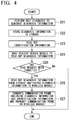
- FIG. 4 is a flowchart showing a diagnosis information transmission operation in the first embodiment of the present invention.
- the processing in the flowchart shown in FIG. 4 is performed at a frequency of, for example, approximately once every several hours to several months.
- the processing is started, first, in the sensor module 10, a process of performing self-diagnosis of the field device 1 to generate diagnosis information indicating a diagnosis result is performed by the calculator 12 (step S21).
- the calculator 12 a process of storing the generated diagnosis information in the storage 13 is performed by the calculator 12 (step S22).
- a process of reading out identification information stored in the storage 24 is performed by the calculator 22 (step S23).
- a process of requesting the sensor module 10 to read the diagnosis information stored in the storage 13 is performed by the calculator 22 (step S24).
- the request for reading the diagnosis information is input to the security unit 15 through the internal communicator 23 of the wireless module 20 and the internal communicator 16 of the sensor module 10.
- step S25 it is determined whether or not to permit the read request (the read request for the diagnosis information) which is output from the calculator 22 of the wireless module 20 (step S25).
- a determination result in step S25 is "YES”.
- step S26 a process of reading out the diagnosis information stored in the storage 13 and outputting the diagnosis information to the wireless module 20 as a response is performed by the calculator 12 in the sensor module 10 (step S26).
- the diagnosis information which is output from the calculator 12 is input to the calculator 22 through the security unit 15 and the internal communicator 16 of the sensor module 10 and the internal communicator 23 of the wireless module 20 in this order.
- a process of attaching the identification information (the identification information which is read out in step S23) to the input diagnosis information and outputting the identification information with the diagnosis information attached thereto to the wireless unit 25 is performed by the calculator 22. Further, in the wireless module 20, a process of generating a communication frame including the diagnosis information and the identification information and transmitting the communication frame from the wireless unit 25 as a wireless signal is performed by the wireless unit 25 (step S27).
- the diagnosis information of the field device 1 is transmitted to a collecting device not shown in the drawing through the Internet.
- the security unit 15 is provided in the sensor module 10, and the security unit 15 permits or rejects a request made to the sensor module 10 by the wireless module 20 in accordance with a rule which is specified in advance. Thereby, since an attack or illegal access to the sensor module 10 that handles sensor values and diagnosis information which are used for process control is rejected by the security unit 15, security can be secured.
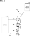
- FIG. 5 is a diagram showing main components of an information collecting system according to the first embodiment of the present invention.
- An information collecting system SY1 shown in FIG. 5 includes the field device 1 and a device management server SV (collecting device), and diagnosis information (second information) transmitted through a communication channel N1 capable of low power consumption long distance wireless communication from the field device 1 is collected by the device management server SV.
- the device management server SV is connected to, for example, the Internet and collects diagnosis information through the communication channel N1 and the Internet.
- the field device 1 is connected to a distributed control system 100.
- the distributed control system 100 is an analog system of the related art which includes field devices 101 and 102 and a controller 110 and exchanges information used for process control using an analog signal.
- the field device 101 is a sensor device of the related art which transmits a measurement result of a sensor using an analog signal.
- the field device 102 is an actuator device of the related art which is controlled using an analog control signal to be transmitted.
- the field devices 101 and 102 do not have a self-diagnosis function.
- the controller 110 is a controller of the related art which acquires a measurement result (analog signal) of a sensor which is transmitted from the field device 101 and transmits a control signal (analog signal) based to the acquired measurement result to control the field device 102.
- the field device 101 is connected to the controller 110 through a transmission line CB1
- the field device 102 is connected to the controller 110 through a transmission line CB2.
- the transmission lines CB1 and CB2 are, for example, 4-20 mA analog signal lines.
- the field device 1 of the present embodiment is connected to the controller 110 of the related art through a transmission line CB3.
- the transmission line CB3 is, for example, a 4-20 mA analog signal line.
- the field device 1 transmits a sensor value (analog signal) to the controller 110 through the transmission line CB3. In this manner, the field device 1 of the present embodiment can be connected to the distributed control system 100 of the related art without making any change to the distributed control system 100 of the related art.
- the field device 1 of the present embodiment has a self-diagnosis function and can transmit diagnosis information indicating a diagnosis result of self-diagnosis through a wireless signal. For this reason, it is possible to collect diagnosis information by only constructing the information collecting system SY1 by providing the device management server SV that collects diagnosis information transmitted from the field device 1 using a wireless signal. That is, the information collecting system SY1 of the present embodiment can collect diagnosis information without making any change to the distributed control system 100 of the related art.
- diagnosis information transmitted from the field device 1 using a wireless signal is collected by the device management server SV.
- diagnosis information of the field device 1 is collected in the device management server SV without going through the controller 110 that handles information used for process control, and thus it is possible to completely separate the information used for process control and the diagnosis information of the field device 1 from each other.
- two pieces of information having different properties can be individually managed by an operator and a worker of a plant. For example, the worker of the plant can change setting related to self-diagnosis without worrying about the convenience of the operator of the plant.
- FIG. 6 is a block diagram showing main components of a field device according to a second embodiment of the present invention.
- a field device 2 of the present embodiment is configured such that a short distance wireless unit 27 (second wireless unit) is added to the wireless module 20 of the field device 1 shown in FIG. 1 . That is, the field device 2 of the present embodiment can perform short distance wireless communication with a terminal device TM (external device).
- TM terminal device
- NFC near field communication
- a short distance wireless unit 27 is operated using power supplied from the terminal device TM in a non-contact manner.
- the short distance wireless unit 27 exchanges various information with the terminal device TM by performing short distance wireless communication in a case where power is supplied from the terminal device TM in a non-contact manner. That is, the short distance wireless unit 27 performs a so-called passive operation.
- the short distance wireless unit 27, which is connected to a calculator 22 of a wireless module 20, outputs information transmitted from the terminal device TM to the calculator 22 and acquires the information transmitted to the terminal device TM from the calculator 22.
- the short distance wireless unit 27 generates a communication frame including information acquired from the calculator 22 and transmits the generated communication frame as a wireless signal.
- the short distance wireless unit 27 generates a communication frame, but a communication frame may be generated by the calculator 22.
- the terminal device TM is a device for performing, for example, maintenance of the field device 2 and various setting of the field device 2.
- the terminal device TM performs short distance wireless communication with the short distance wireless unit 27 to be capable of accessing (reading-out and writing) information stored in a storage 13 of a sensor module 10 and information stored in a storage 24 of the wireless module 20.
- the terminal device TM is a dedicated terminal for maintaining a general-purpose information device, such as a smart phone, a tablet, and a personal computer, or the field device 2.
- short distance wireless communication using the short distance wireless unit 27 is performed, in addition to wireless communication using a wireless unit 25.
- a request made to the sensor module 10 by the wireless module 20 may be given through the short distance wireless unit 27 of the wireless module 20 (the short distance wireless unit 27 serves as a request source), in addition to a case where a request is given through the wireless unit 25 of the wireless module 20 (the wireless unit 25 serves as a request source).
- a rule for permitting or rejecting a request made to the sensor module 10 by the wireless module 20 (a rule in the latter case) is added.
- FIG. 7 is a diagram showing an example of a rule specified by a security unit of the field device in the second embodiment of the present invention.
- a rule used by the security unit 15 is specified on the basis of the type of request made to the sensor module 10 by the wireless module 20, the type of information to be requested, and a request source. That is, the security unit 15 performs the above-described permission or rejection according to where a request source is in the wireless module 20 and what request is made for which information among pieces of information used by the sensor module 10.
- a “wireless unit (wireless unit 25)” and a “short distance wireless unit (short distance wireless unit 27)” are specified as request sources.
- “read request (Read)” and “write request (Write)” are specified as the type of request made to the sensor module 10 by the wireless module 20, and "sensor value”, “sensor settings”, “diagnosis information”, “diagnosis settings”, and “wireless settings” are specified as the type of information to be requested.
- the security unit 15 rejects the "write request”.
- the security unit 15 permits the "write request”.
- the security unit 15 permits or rejects a request on the basis of, for example, information of a request source which is imparted by the calculator 22 for each request.
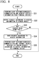
- FIG. 8 is a flowchart showing an example of an operation of the field device according to the second embodiment of the present invention.
- the flowchart shown in FIG. 8 shows operations when short distance wireless communication is performed between the field device 2 and the terminal device TM. Processing in the flowchart shown in FIG. 8 is started when the terminal device TM is disposed in proximity to the short distance wireless unit 27 and the short distance wireless unit 27 is operated using power supplied from the terminal device TM in a non-contact manner.
- a process of performing short distance wireless communication and acquiring access information transmitted from the terminal device TM is performed by the short distance wireless unit 27 of the wireless module 20 (step S31).
- the above-described access information is information including the type of access (reading-out, writing, or the like) performed on the field device 2 by the terminal device TM and the type (a sensor value, diagnosis information, or the like) of information to be accessed.
- the access information acquired by the short distance wireless unit 27 includes "read-out" as the above-described type of access and includes a "sensor value” as the above-described type of information to be accessed.
- a process of outputting a request according to the above-described access information (here, a read request for a sensor value) to the sensor module 10 is performed by the calculator 22 (step S32).
- the request which is output from the calculator 22 is input to the security unit 15 through an internal communicator 23 of the wireless module 20 and an internal communicator 16 of the sensor module 10.
- step S33 it is determined whether or not a request according to access information (a read request for a sensor value) is permitted (step S33).
- a request source is a "short distance wireless unit”
- "permission (Accept)” is specified for "read request (Read)” of "sensor value”
- a determination result in step S33 is "YES”.
- the request according to the access information is input to a calculator 12 of the sensor module 10.
- the request is performed by the calculator 12 (step S34). Specifically, in the sensor module 10, a process of reading out a sensor value stored in the storage 13 and outputting the sensor value to the wireless module 20 as a response is performed by the calculator 12.
- the sensor value which is output from the calculator 12 is input to the short distance wireless unit 27 through the security unit 15 and the internal communicator 16 of the sensor module 10 and the internal communicator 23 and the calculator 22 of the wireless module 20 in this order.
- a process of performing short distance wireless communication and transmitting a result obtained by performing the request according to the access information to the terminal device TM is performed by the short distance wireless unit 27 (step S35). Specifically, a process of generating a communication frame including a sensor value and transmitting the generated communication frame to the terminal device TM through short distance wireless communication as a wireless signal is performed by the short distance wireless unit 27. A result obtained by performing the request according to the access information transmitted from the terminal device TM is acquired by the terminal device TM through the above-described processing.
- the short distance wireless unit 27 is provided in the wireless module 20, access information is acquired by performing short distance wireless communication with the terminal device TM, and a request according to the access information is performed. In addition, a result obtained by performing the request according to the access information by performing short distance wireless communication with the terminal device TM is transmitted. Thereby, it is possible to perform maintenance of the field device 2 and various setting of the field device 2 using the terminal device TM. Since the maintenance of the field device 2 and various setting can be performed using the terminal device TM in a non-contact manner, there is no problem even when the field device 2 is installed in a place (an explosion-proof area) where explosion proof is required.
- FIG. 9 is a block diagram showing main components of a field device according to a third embodiment of the present invention.
- components equivalent to the components shown in FIG. 1 are denoted by the same reference numerals and signs.
- a field device 3 of the present embodiment is configured such that a power storage 28 is provided in the wireless module 20 of the field device 1 shown in FIG. 1 .
- the power storage 28 stores power (a portion of power) supplied to the wireless module 20 from a power supply 17 of the sensor module 10.
- the power storage 28 stores a portion of power supplied through an internal communicator 16 of the sensor module 10 and an internal communicator 23 of the wireless module 20.
- the power supply 17 of the sensor module 10 and the power storage 28 may be connected to each other so as to store power which is directly supplied to the power storage 28 from the power supply 17.
- a large-capacity capacitor or a super capacitor for example, an electric double layer capacitor, a lithium ion capacitor, or the like.
- a sleep state is maintained until power required to perform wireless communication in the wireless unit 25 is stored in the power storage 28. After power required to perform wireless communication in the wireless unit 25 is stored in the power storage 28, the above-described sleep state is canceled, and an operation of acquire necessary information (for example, diagnosis information) from the sensor module 10 and transmitting the acquired information from the wireless unit 25 as a wireless signal is performed.
- the wireless communication is performed by the wireless unit 25
- power stored in the power storage 28 is supplied to the wireless unit 25.
- FIG. 10 is a diagram showing an operation of the field device according to the third embodiment of the present invention.
- a graph showing an example of changes in a current flowing to the power storage 28 over time and a graph showing an example of changes in a voltage appearing in the power storage 28 over time are shown.
- a current flowing into the power storage 28 (a charged current I1) and a current flowing out of the power storage 28 (a discharged current 12) are shown.
- a sleep state in the wireless module 20 is maintained until time t1. Accordingly, power supplied to the wireless module 20 from the sensor module 10 is stored in the power storage 28 until time t1 in FIG. 10 .
- the charged current I1 of the power storage 28 is constant while power is stored in the power storage 28, and a voltage appearing in the power storage 28 is gradually increased.
- the charged current I1 flowing to the power storage 28 is set to zero as shown in FIG. 10 , and the voltage of the power storage 28 becomes constant.
- a timing signal is output from a timing generator 21 to a calculator 22 at time t2, so that a sleep state in the wireless module 20 is canceled, and wireless communication using the wireless unit 25 is performed between time t2 and time t3. Accordingly, power stored in the power storage 28 is supplied to the wireless unit 25 between time t2 and time t3 in FIG. 10 . While power is supplied from the power storage 28 to the wireless unit 25, a constant discharged current I2 larger than the charged current 11 flows as shown in FIG. 10 , and a voltage appearing in the power storage 28 is gradually decreased.
- time t3 at which wireless communication using the wireless unit 25 is terminated elapses, the wireless module 20 is set to be in a sleep state again, and the storage of power in the power storage 28 is restarted.
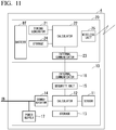
- FIG. 11 is a block diagram showing main components of a field device according to a fourth embodiment of the present invention.
- components equivalent to the components shown in FIG. 1 are denoted by the same reference numerals and signs.
- a field device 4 of the present embodiment is configured such that a battery BT is provided in the wireless module 20 of the field device 1 shown in FIG. 1 .
- the field device 4 of the present embodiment prevents trouble occurring around a power supply by providing the battery BT in the wireless module 20 and obtaining power required in the wireless module 20 from the battery BT.
- the battery BT supplies power to each block of the wireless module 20.
- a battery BT for example, a primary battery, a secondary battery, a fuel cell, a condenser, and a capacitor (including a super capacitor) can be used.
- a battery that performs energy harvesting can be used as the battery BT.
- the battery BT is provided in the wireless module 20, and power required in the wireless module 20 is obtained from the battery BT.
- power supplied from the power supply 17 of the sensor module 10 to the wireless module 20 is reduced (or eliminate) power supplied from the power supply 17 of the sensor module 10 to the wireless module 20.
- FIG. 12 is a block diagram showing main components of a field device according to a fifth embodiment of the present invention.
- a field device 5 of the present embodiment is configured such that the security unit 15 provided in the sensor module 10 of the field device 1 shown in FIG. 1 is provided in a wireless module 20.
- the security unit 15 is provided between a calculator 22 and an internal communicator 23 in the wireless module 20.
- permission or rejection of a request made to a sensor module 10 by the wireless module 20 is performed by the security unit 15 provided in the wireless module 20. Since a request rejected by the security unit 15 is not input to the sensor module 10, it is possible to prevent an attack or illegal access from being performed on the sensor module 10 that handles sensor values and diagnosis information which are used for process control, similar to the first embodiment.
- the security unit 15 can be retrofitted by attaching the wireless module 20 including the security unit 15 to a field device including only the sensor module 10 that does not include the security unit 15. Thereby, it is possible to prevent an attack or illegal access from being performed on the sensor module 10 even when the security unit 15 is not provided in the sensor module 10.
- the security unit 15 is not necessarily provided in the sensor module 10 or the wireless module 20 and may be provided separately from the sensor module 10 and the wireless module 20.
- the security unit 15 may be provided between the sensor module 10 and the wireless module 20, apart from the sensor module 10 and the wireless module 20.
- FIG. 13 is a diagram showing main components of an information collecting system according to a sixth embodiment of the present invention.
- An information collecting system SY2 shown in FIG. 13 includes a field device 1, a controller CT, and a device management server SV (collecting device), and the device management server SV collects diagnosis information (third information) transmitted from the controller CT in addition to diagnosis information (second information) transmitted from the field device 1.
- the diagnosis information of the field device 1 and the controller CT is transmitted through a communication channel N1 capable of low power consumption long distance wireless communication.
- the controller CT is configured such that a self diagnoser 31 and a wireless unit 32 are added to the controller 110 of the related art shown in FIG. 5 . Therefore, an analog distributed control system 100 of the related art which exchanges information used for process control using an analog signal is constructed by field devices 101 and 102 and the controller CT.
- the self diagnoser 31 performs self-diagnosis of the controller CT to perform a process of generating diagnosis information (third information) indicating a diagnosis result.
- the wireless unit 32 transmits the diagnosis information generated by the self diagnoser 31 as a wireless signal.
- the wireless unit 32 performs wireless communication through, for example, a communication channel (LPWAN) capable of low power consumption long distance wireless communication, similar to the wireless unit 25 shown in FIG. 1 .
- LPWAN communication channel
- the controller CT configured such that the self diagnoser 31 and the wireless unit 32 are provided in the controller 110 of the related art shown in FIG. 5 is prepared, and diagnosis information of the controller CT is transmitted using a wireless signal.
- the device management server SV collects diagnosis information transmitted from the controller CT in addition to diagnosis information transmitted from the field device 1. Thereby, in the information collecting system SY2 of the present embodiment, diagnosis information of the controller CT can be completely separated from information used for process control, in addition to diagnosis information of the field device 1.
- the present invention is not limited to the above-described embodiments, and modifications can be freely made without departing from the scope of the present invention.
- the above-described first to sixth embodiments can be appropriately combined with each other.
- the field devices 2 to 5 according to the second to fifth embodiments can be applied to the information collecting system SY1 according to the first embodiment and the information collecting system SY2 according to the sixth embodiment.
- the configuration of the field device 2 according to the second embodiment may be applied to the field devices 3 to 5 according to the third to fifth embodiments, and the field devices 3 to 5 according to the third to fifth embodiments may be configured such that the short distance wireless unit 27 is provided in the wireless module 20.
- the configuration of the field device 5 according to the fifth embodiment may be applied to the field devices 2 to 4 according to the second to fourth embodiments, and the field devices 2 to 4 according to the second to fourth embodiments may be configured such that the security unit 15 is provided in the wireless module 20.
- the configuration of the field device 4 according to the fourth embodiment may be applied to the field device 3 according to the third embodiment, and the field device 3 according to the third embodiment can be configured such that the battery BT is provided together with the power storage 28.
- wireless communication is performed using power of the power storage 28 when the charging of the power storage 28 has been completed, and thus it is possible to extend the life of the battery BT by suppressing the power consumption of the battery BT.
- wireless communication is performed using power of the battery BT when the charging of the power storage 28 has not been completed, and thus it is possible to perform wireless communication at all times by cancelling a sleep state of the wireless module 20.
- the field devices 1 to 5 are sensor devices (for example, a flow meter, a temperature sensor, or the like).
- the field devices 1 to 5 may be valve devices such as flow control valves and on-off valves, actuator devices such as fans and motors, and other devices installed on a plant site.
- the field devices 1 to 5 are actuators, for example, a valve and the like are provided.
- an operation of causing the communicator 14 to receive information indicating an operation amount transmitted through the transmission line CB, causing the calculator 12 to store information indicating an operation amount received by the communicator 14 in the storage 13, and causing the calculator 12 to operate a valve and the like using information obtained by performing predetermined processing on the information indicating the operation amount is performed.
- Plants where the field devices 1 to 5 are installed include a plant that manages and controls a well source such as a gas field or an oil field and the surroundings thereof, a plant that manages and controls power generation of such as water power, thermal power, and nuclear power, a plant that manages and controls energy harvesting such as sunlight and wind power, and a plant that manages and controls water and sewage, dams, and the like, in addition to an industrial plant of such as chemistry.
- a plant that manages and controls a well source such as a gas field or an oil field and the surroundings thereof
- a plant that manages and controls power generation of such as water power, thermal power, and nuclear power a plant that manages and controls energy harvesting such as sunlight and wind power
- a plant that manages and controls water and sewage, dams, and the like in addition to an industrial plant of such as chemistry.
- the above-described plants are merely examples and the present invention is not limited to the above-described plants.
Landscapes
- Engineering & Computer Science (AREA)
- Computer Security & Cryptography (AREA)
- Computer Networks & Wireless Communication (AREA)
- Signal Processing (AREA)
- General Engineering & Computer Science (AREA)
- Physics & Mathematics (AREA)
- General Physics & Mathematics (AREA)
- Automation & Control Theory (AREA)
- Computing Systems (AREA)
- Computer Hardware Design (AREA)
- Manufacturing & Machinery (AREA)
- Quality & Reliability (AREA)
- Testing And Monitoring For Control Systems (AREA)
- Selective Calling Equipment (AREA)
Abstract
Description
- The present invention relates to a field device, an information collecting system, and an information collecting method.
- The present application claims priority based on Japanese patent application
2018-244970, filed on December 27, 2018 - In plants, factories, and the like (hereinafter, collectively referred to simply as "plants"), distributed control systems (DCS) have been constructed, and advanced automatic operation has been realized therewith. This distributed control system is a control system in which controllers controlling field equipment (a measurement device, an operation device, a display, a notifier, and other device) which are called field devices are distributed in each of several control loops.
- In such a distributed control system, an operation in which the controller acquires measurement results of the measurement device (for example, a sensor), obtains an operation amount of the operation device (for example, an actuator) in accordance with the measurement results, and operates the operation device in accordance with the operation amount is repeated. For this reason, information used for process control such as a measurement result of the measurement device and an operation amount of the operation device is exchanged between the controller and the field device.
- Published Japanese Translation No.
H10-508129 Patent Document 1, the field device is capable of wirelessly communicating with a wireless transceiver. Wireless communication with the field device is performed using the wireless transceiver, and thus it is possible to access a function of the field device which is not accessed by the controller of the distributed control system and to access a field device that cannot communicate with the controller. - In the distributed control system disclosed in
Patent Document 1, a device used to perform wireless communication with the field device is a wireless transceiver used in a plant. For this reason, it is considered that security problems such as the leakage of various information of the field device outside of the plant and access to the field device from outside of the plant do not occur. - However, in a case where the field device is connected to the Internet using a technique called the Internet of Things (IoT) or the Industrial Internet of Things (IIoT), it is considered that a third party may be able to gain access to the field device. As described above, since information used for process control is exchanged between the controller and the field device, it is necessary to secure sufficient security in a case where the field device is connected to the Internet. The Internet is an example of a public line, and it is also considered that a third party may be able to gain access to the field device through a public line other than the Internet.
- One aspect of the present invention provides a field device which can be connected to a public line such as the Internet while securing security, an information collecting system and an information collecting method which are capable of collecting information from the field device while securing security.
- A field device (1 to 5) according to one aspect of the present invention may include a first processor (10) configured to perform a process of communicating first information used for process control and a process of generating second information including a diagnosis result obtained by performing self-diagnosis of the field device, a second processor (20) including a first wireless unit (25) configured to perform wireless communication, the second processor being configured to request the first processor to read at least the second information and to perform a process of transmitting, from the first wireless unit, the second information obtained through the read request as a wireless signal, and a security unit (15) configured to permit or reject a request made to the first processor by the second processor in accordance with a rule which is specified in advance.
- In the above-described field device, the rule may be specified on the basis of a type of request made to the first processor by the second processor and a type of information to be requested.
- In the above-described field device, the security unit may be configured to reject a write request for the first information or the second information in a case where the write request is made through the first wireless unit.
- In the above-described field device, identification information which is uniquely determined may be allocated to the second processor. The second processor may be configured to transmit, from the first wireless unit, the identification information attached to the second information obtained through the read request as a wireless signal.
- In the above-described field device, the security unit may be provided in the first processor.
- In the above-described field device, the security unit may be provided in the second processor.
- In the above-described field device, the second processor may further include a second wireless unit (27) configured to perform short distance wireless communication with an external device.
- In the above-described field device, the security unit may be configured to permit a write request for the first information or the second information in a case where the write request is made through the second wireless unit.
- In the above-described field device, the first wireless unit may be configured to perform low power consumption long distance wireless communication.
- In the above-described field device, the first processor may include a power supply (17) configured to generate power required for an operation of at least the first processor from a current flowing through a transmission line (CB) used for communication of the first information.
- In the above-described field device, the second processor may further include a power storage (28) configured to store power supplied from the power supply and to obtain power required for an operation of at least the first wireless unit.
- In the above-described field device, the second processor may further include a battery (BT) configured to supply power required for an operation of the second processor.
- An information collecting system (SY1, SY2) according to one aspect of the present invention may include the field device (1 to 5) described above, and a collecting device (SV) configured to collect the second information transmitted from the field device.
- The above-described information collecting system may further include a controller configured to control the field device and to perform self-diagnosis of the controller to perform a process of generating third information indicating a diagnosis result. The collecting device may be configured to collect the third information transmitted from the controller in addition to the second information transmitted from the field device.
- An information collecting method according to one aspect of the present invention may include transmitting the second information from the field device described above, and collecting the second information transmitted from the field device.
- According to the one aspect of the present invention, it is possible to connect a field device to a public line such as the Internet while securing security and to collect information from the field device while securing security.
-
-
FIG. 1 is a block diagram showing main components of a field device according to a first embodiment of the present invention. -
FIG. 2 is a diagram showing an example of a rule specified by a security unit of the field device according to the first embodiment of the present invention. -
FIG. 3 is a flowchart showing a sensor value transmission operation in the first embodiment of the present invention. -
FIG. 4 is a flowchart showing a diagnosis information transmission operation in the first embodiment of the present invention. -
FIG. 5 is a diagram showing main components of an information collecting system according to the first embodiment of the present invention. -
FIG. 6 is a block diagram showing main components of a field device according to a second embodiment of the present invention. -
FIG. 7 is a diagram showing an example of a rule specified by a security unit of the field device in the second embodiment of the present invention. -
FIG. 8 is a flowchart showing an example of an operation of the field device according to the second embodiment of the present invention. -
FIG. 9 is a block diagram showing main components of a field device according to a third embodiment of the present invention. -
FIG. 10 is a diagram showing an operation of the field device according to the third embodiment of the present invention. -
FIG. 11 is a block diagram showing main components of a field device according to a fourth embodiment of the present invention. -
FIG. 12 is a block diagram showing main components of a field device according to a fifth embodiment of the present invention. -
FIG. 13 is a diagram showing main components of an information collecting system according to a sixth embodiment of the present invention. - Hereinafter, a field device, an information collecting system, and an information collecting method according to an embodiment of the present invention will be described in detail with reference to the accompanying drawings. Hereinafter, first, an outline of an embodiment of the present invention will be described, and then details of the embodiment of the present invention will be described.
- Prior to about 1990, a distributed control system was an analog system in which a controller and a field device were connected to each other through an analog signal line (for example, a 4-20 mA analog signal line). In such a distributed control system, information used for process control (a measurement result of a measurement device, an operation amount of an operation device, and the like) was exchanged between the controller and the field device using an analog signal. An example of process control was control for adjusting a flow rate of a fluid by changing the opening (operation amount) of a value through which the fluid flowed in accordance with the value of the flow rate (sensor value) of the fluid which is a measurement result.
- After around 1990, a digitized distributed control system appeared. In the distributed control system, a controller and a field device became intelligent, and a self-diagnosis function (a function of diagnosing its own state) was provided. In such a distributed control system, information used for process control was exchanged between the controller and the field device using a digital signal, and information indicating self-diagnosis results in the controller and the field device was collected in a high-order device management server using a digital signal. In recent years, a digital signal has also been exchanged between the controller and the field device through industrial wireless communication.
- In the plant, there are an operator who operates a plant and a worker who maintains the plant. The operator of the plant is responsible for monitoring information used for process control, immediately coping with any problems, and allowing the plant to be in operation appropriately. On the other hand, the worker of the plant is responsible for inspecting equipment, devices, facilities, and the like provided in the plant, performing repair, replacement, and the like if necessary, and allowing the equipment, the devices, the facilities, and the like to be operated appropriately.
- In the above-described digitalized distributed control system, two pieces of information having different properties (information used for process control and information indicating self-diagnosis results) are used. The information used for process control is information to be managed by an operator of a plant and is information required to be monitored and controlled in real time because it is directly related to the quality and productivity of a product. On the other hand, the information indicating self-diagnosis results is information to be managed by a worker of the plant and is information which may be confirmed with a frequency of approximately once every several hours to several months because the information is not directly related to the quality and productivity of a product and is not likely to rapidly change.
- It is preferable that such two pieces of information having different properties be completely separated and managed individually by the operator and the worker of the plant. However, in a current distributed control system, information indicating a self-diagnosis result is collected in a device management server via a controller that handles information used for process control, and thus it is difficult to completely separate the two pieces of information having different properties. For this reason, for example, even when only the settings related to self-diagnosis are changed, it may be necessary to change the settings of the controller that handles information used for process control.
- When paths of the above-described two pieces of information having different properties are separated from each other, it is considered that the two pieces of information having different properties can be completely separated. For example, when a field device is connected to the Internet using a technique called IoT or IIoT and information indicating a self-diagnosis result is collected by a collecting device connected to the Internet, it is considered that the information indicating a self-diagnosis result can be completely separated from information used for process control. However, in a case where a field device is connected to the Internet which is easily accessible by a third party, it is necessary to secure sufficient security. This is the same as in a case where a field device is connected to a public line other than the Internet.
- In embodiments of the present invention, a security unit is provided between a first processor and a second processor. The first processor performs a process of communicating first information used for process control and a process of performing self-diagnosis for the field device and generating second information indicating a diagnosis result. The second processor includes a first wireless unit for performing wireless communication. In addition, security is secured by the security unit permitting or rejecting a request given to the first processor by the second processor in accordance with a rule which is specified in advance.
-
FIG. 1 is a block diagram showing main components of a field device according to a first embodiment of the present invention. As shown inFIG. 1 , afield device 1 of the present embodiment includes a sensor module 10 (first processor) and a wireless module 20 (second processor), and performs transmission of a sensor value (first information) used for process control and transmission of diagnosis information (second information) indicating a self-diagnosis result of the host device through different paths. - The
field device 1 is connected to a controller (not shown) that forms the core of a distributed control system through a transmission line CB. The transmission line CB is, for example, a 4-20 mA analog signal line. However, the transmission line CB is not limited to the 4-20 mA analog signal line, and may be another analog signal line or may be a digital signal line. Thefield device 1 is connected to a public line in a wireless manner. In the present embodiment, a case where thefield device 1 is connected to the Internet which is a type of public line in a wireless manner will be described as an example. Thefield device 1 transmits the above-described sensor value to a controller not shown in the drawing through the transmission line CB and transmits the above-described diagnosis information as a wireless signal. The diagnosis information transmitted from thefield device 1 is collected in a collecting device (not shown) connected to the Internet. - The
sensor module 10 includes asensor 11, acalculator 12, astorage 13, acommunicator 14, asecurity unit 15, aninternal communicator 16, and apower supply 17. Thesensor module 10 having such a configuration performs a process of transmitting a sensor value used for process control (transmission process through the transmission line CB). Thesensor module 10 performs self-diagnosis for thefield device 1 to perform a process of generating diagnosis information. - The
sensor 11 measures a physical quantity to be measured (for example, a temperature, a pressure, a flow rate, and the like) and outputs a measurement result as a sensor value. Thecalculator 12 takes in the sensor value output from thesensor 11, stores the sensor value in thestorage 13, reads out the sensor value stored in thestorage 13, performs predetermined processing on the sensor value as necessary, and transmits the processed sensor value to thecommunicator 14. In addition, thecalculator 12 performs self-diagnosis for thefield device 1, generates diagnosis information indicating a diagnosis result, and stores the generated diagnosis information in thestorage 13. Furthermore, the diagnosis information includes, for example, information indicating an ambient temperature of thefield device 1, information indicating an output voltage (power voltage) of thepower supply 17, information indicating an abnormality of an internal circuit of thefield device 1, information indicating an abnormality of a value processed in each unit of thefield device 1, and other information indicating the state of thefield device 1. - The
calculator 12 performs processing according to a request permitted in thesecurity unit 15 among requests output from thewireless module 20. For example, in a case where a request for reading diagnosis information stored in thestorage 13 is output from thewireless module 20 and is permitted in thesecurity unit 15, thecalculator 12 reads out the diagnosis information stored in thestorage 13 and outputs the diagnosis information to thewireless module 20 as a response. - The
storage 13 stores a sensor value output from thecalculator 12 and diagnosis information generated by thecalculator 12. Thestorage 13 stores setting information regarding thesensor 11 and setting information regarding self-diagnosis. Thestorage 13 may store setting information regarding a wireless unit 25 (to be described later in detail) provided in thewireless module 20. Thestorage 13 is realized by a non-volatile memory such as a flash read only memory (ROM) or an electrically erasable and programmable ROM (EEPROM). Thestorage 13 may be realized by a volatile memory such as a random access memory (RAM). - The
communicator 14 is connected to the transmission line CB, and transmits a sensor value read out by thecalculator 12 through the transmission line CB. Specifically, thecommunicator 14 generates a communication frame including the sensor value read out by thecalculator 12 and transmits the generated communication frame to the transmission line CB. Furthermore, here, thecommunicator 14 generates a communication frame, but a communication frame may be generated by thecalculator 12. - The
security unit 15 permits or rejects a request made to thesensor module 10 by thewireless module 20 according to a rule which is specified in advance. Only a request permitted by thesecurity unit 15 among requests made to thesensor module 10 by thewireless module 20 is input to thecalculator 12. Thesecurity unit 15 is provided to secure the security of thefield device 1 connected to the Internet by thewireless module 20. Specifically, thesecurity unit 15 is provided to prevent an attack or illegal access from being performed on thesensor module 10 that handles sensor values and diagnosis information which are used for process control. - The above-described rule used by the
security unit 15 is specified on the basis of the type of request made to thesensor module 10 by thewireless module 20 and the type of information to be requested. That is, thesecurity unit 15 performs the above-described permission and rejection according to what request thewireless module 20 makes for which information among pieces of information used by thesensor module 10. -
FIG. 2 is a diagram showing an example of a rule specified by the security unit of the field device in the first embodiment of the present invention. In the example shown inFIG. 2 , "read request (Read)" and "write request (Write)" are specified as the type of request made to thesensor module 10 by thewireless module 20, and "sensor value", "sensor settings", "diagnosis information", "diagnosis settings", and "wireless settings" are specified as the type of information to be requested. The "sensor settings" are setting information regarding thesensor 11, the "diagnosis settings" is setting information regarding self-diagnosis, and the "wireless settings" is setting information regarding the wireless unit 25 (to be described later in detail) provided in thewireless module 20. - In the example shown in
FIG. 2 , with respect to "read request", "permission (Accept)" is specified for all of "sensor value ", "sensor settings", "diagnosis information", "diagnosis settings", and "wireless settings". On the other hand, with respect to "write request", "permission (Accept)" is specified for "diagnosis settings" and "wireless settings", but "rejection (Block)" is specified for "sensor value ", "sensor settings", and "diagnosis information". Since the "sensor value" and the "sensor settings" are important information related to process control and the "diagnosis information" is important information indicating the state of thefield device 1, the "write request" of which the content is changeable is specified so as to be "rejected". - Referring back to
FIG. 1 , theinternal communicator 16 is connected to the internal communicator 23 (to be described later in detail) provided in thewireless module 20, and transmits and receives various information to and from theinternal communicator 23. Theinternal communicator 16 is provided to allow thesensor module 10 and thewireless module 20 to exchange various information. Furthermore, theinternal communicator 16 can also supply power generated by thepower supply 17 to theinternal communicator 23 provided in thewireless module 20. - The
power supply 17 generates power required for at least thesensor module 10 to operate from a current flowing through the transmission line CB. Furthermore, thepower supply 17 may generate power required for thefield device 1 to operate (power required for thewireless module 20 and the like to operate, in addition to the sensor module 10). Power generated by thepower supply 17 is supplied to each block of thesensor module 10. In addition, power generated by thepower supply 17 is also supplied to thewireless module 20 through theinternal communicator 16. - The
wireless module 20 includes atiming generator 21, acalculator 22, aninternal communicator 23, astorage 24, and a wireless unit 25 (first wireless unit). Such awireless module 20 allows thefield device 1 to perform wireless communication. Thewireless module 20 is provided, and thus, for example, thefield device 1 can be connected to the Internet in a wireless manner. Thewireless module 20 requests thesensor module 10 to read out at least diagnosis information, and performs a process of transmitting diagnosis information obtained through the read request from thewireless unit 25 as a wireless signal. - The
wireless module 20 may be attachable to thesensor module 10. For example, thewireless module 20 may be attached to thesensor module 10 by inserting thewireless module 20 into a slot provided in thefield device 1 in advance. In this manner, for example, it is possible to reduce the cost of thefield device 1 and to allow thefield device 1 to retroactively perform wireless communication by retrofitting thewireless module 20 to thefield device 1 installed while being connected to the controller through the transmission line CB in advance. Thewireless module 20 may be incorporated in thefield device 1 from the beginning. Thewireless module 20 may be removable or may be non-removable. - The
timing generator 21 generates a timing signal for specifying a timing for performing wireless communication. Thecalculator 22 performs processing for performing wireless communication by thewireless unit 25 at a timing specified by the timing signal generated by thetiming generator 21. For example, thecalculator 22 performs processing for transmitting diagnosis information stored in thestorage 13 of thesensor module 10 from thewireless unit 25 as a wireless signal. - Specifically, the
calculator 22 requests thesensor module 10 to read the diagnosis information stored in thestorage 13 of thesensor module 10. Thecalculator 22 reads out identification information (to be described later in detail) stored in thestorage 24. Thecalculator 22 transmits a combination of the diagnosis information obtained through the above-described read request and the identification information read out from thestorage 24 to thewireless unit 25 as a wireless signal. The identification information is attached to the diagnosis information, whereby it is possible to easily identify a transmission source of the diagnosis information. - The
internal communicator 23 is connected to theinternal communicator 16 provided in thesensor module 10 and transmits and receives various information to and from theinternal communicator 16. Theinternal communicator 23 is provided to allow thesensor module 10 and thewireless module 20 to exchange various information together with theinternal communicator 16. Theinternal communicator 23 can also receive power supplied from theinternal communicator 16. Power received by theinternal communicator 23 is supplied to each block of thewireless module 20. - The
storage 24 stores uniquely determined identification information which is allocated to thewireless module 20 in advance. The identification information is information used to identify the wireless module 20 (or thefield device 1 provided with the wireless module 20), and for example, an IP address and an address in an EUI64 format can be used. Thestorage 24 may store setting information regarding thewireless unit 25. The setting information regarding thewireless unit 25 is stored in any one of thestorage 13 of thesensor module 10 and thestorage 24 of thewireless module 20. Thestorage 24 may be realized by a non-volatile memory or may be realized by a volatile memory. Since thestorage 24 is required to store the above-described identification information, the storage may be realized by a non-volatile memory. - The
wireless unit 25 transmits a signal output from thecalculator 22 as a wireless signal. For example, thewireless unit 25 generates a communication frame including diagnosis information with identification information attached thereto by thecalculator 22 and transmits the communication frame as a wireless signal. Thewireless unit 25 generates the communication frame, but the communication frame may be generated by thecalculator 22. Thewireless unit 25 receives a wireless signal transmitted from the outside and outputs the received wireless signal to thecalculator 22. Thewireless unit 25 performs wireless communication through, for example, a communication channel (low power wide area network: LPWAN) through which low power consumption long distance wireless communication can be performed. The above-described low power consumption long distance wireless communication is wireless communication based on a communication standard such as LoRa (registered trademark). - The
field device 1 is connected to the Internet by thewireless module 20 in a wireless manner. For this reason, for example, it is considered that a request for various information stored in thestorage 13 of the sensor module 10 (a read request, a write request) is transmitted to thefield device 1 through the Internet. The above-described request transmitted through the Internet is received by thewireless unit 25 and output to thecalculator 22, and is then output to thesensor module 10 from thewireless module 20. For this reason, in a case where the above-described request is transmitted through the Internet, it can be said that a request made to thesensor module 10 by thewireless module 20 can be performed through thewireless unit 25 of the wireless module 20 (the request is made when thewireless unit 25 serves as a request source). - Next, operations of the field device according to the first embodiment of the present invention will be described. Hereinafter, an operation when a sensor value is transmitted to the controller (a sensor value transmission operation) and an operation of transmitting diagnosis information to the collecting device connected to the Internet (diagnosis information transmission operation) will be described.
-
FIG. 3 is a flowchart showing a sensor value transmission operation in the first embodiment of the present invention. The processing in the flowchart shown inFIG. 3 is performed at fixed time intervals (for example, at intervals of one second). When the processing is started, first, in thesensor module 10, a process of taking in a sensor value output from thesensor 11 and storing the sensor value in thestorage 13 is performed by the calculator 12 (step S11). - Next, in the
sensor module 10, a process of reading out the sensor value stored in thestorage 13 and outputting the sensor value to thecommunicator 14 is performed by the calculator 12 (step S12). Further, in thesensor module 10, a process of generating a communication frame including a sensor value (a sensor value output from the calculator 12) and transmitting the communication frame to the transmission line CB is performed by the communicator 14 (step S13). Through the above-described processes, the sensor value of thesensor 11 is transmitted to a controller not shown in the drawing through the transmission line CB. -
FIG. 4 is a flowchart showing a diagnosis information transmission operation in the first embodiment of the present invention. The processing in the flowchart shown inFIG. 4 is performed at a frequency of, for example, approximately once every several hours to several months. When the processing is started, first, in thesensor module 10, a process of performing self-diagnosis of thefield device 1 to generate diagnosis information indicating a diagnosis result is performed by the calculator 12 (step S21). Next, in thesensor module 10, a process of storing the generated diagnosis information in thestorage 13 is performed by the calculator 12 (step S22). - Subsequently, in the
wireless module 20, a process of reading out identification information stored in thestorage 24 is performed by the calculator 22 (step S23). Subsequently, in thewireless module 20, a process of requesting thesensor module 10 to read the diagnosis information stored in thestorage 13 is performed by the calculator 22 (step S24). The request for reading the diagnosis information is input to thesecurity unit 15 through theinternal communicator 23 of thewireless module 20 and theinternal communicator 16 of thesensor module 10. - Then, in the
security unit 15, it is determined whether or not to permit the read request (the read request for the diagnosis information) which is output from thecalculator 22 of the wireless module 20 (step S25). Referring toFIG. 2 , since "permission (Accept)" is specified for "read request (Read)" of "diagnosis information", a determination result in step S25 is "YES". Thereby, the read request which is output from thecalculator 22 of thewireless module 20 is input to thecalculator 12 of thesensor module 10. - When the read request for the diagnosis information is input to the
calculator 12, a process of reading out the diagnosis information stored in thestorage 13 and outputting the diagnosis information to thewireless module 20 as a response is performed by thecalculator 12 in the sensor module 10 (step S26). The diagnosis information which is output from thecalculator 12 is input to thecalculator 22 through thesecurity unit 15 and theinternal communicator 16 of thesensor module 10 and theinternal communicator 23 of thewireless module 20 in this order. - Then, in the
wireless module 20, a process of attaching the identification information (the identification information which is read out in step S23) to the input diagnosis information and outputting the identification information with the diagnosis information attached thereto to thewireless unit 25 is performed by thecalculator 22. Further, in thewireless module 20, a process of generating a communication frame including the diagnosis information and the identification information and transmitting the communication frame from thewireless unit 25 as a wireless signal is performed by the wireless unit 25 (step S27). Through the above-described processes, the diagnosis information of thefield device 1 is transmitted to a collecting device not shown in the drawing through the Internet. - Referring to
FIG. 2 , "rejection (Block)" is specified for "write request (Write)" of each of "sensor value", "sensor settings", and "diagnosis information". For this reason, in a case where "write request" of each of "sensor value", "sensor settings", and "diagnosis information" is output to thesensor module 10 from thewireless module 20, a determination result in step S25 is "NO", and a series of processes shown inFIG. 4 is terminated. That is, "write request" of each of "sensor value", "sensor settings", and "diagnosis information" is rejected by thesecurity unit 15 and is not input to thecalculator 12. - As described above, in the
field device 1 of the present embodiment, thesecurity unit 15 is provided in thesensor module 10, and thesecurity unit 15 permits or rejects a request made to thesensor module 10 by thewireless module 20 in accordance with a rule which is specified in advance. Thereby, since an attack or illegal access to thesensor module 10 that handles sensor values and diagnosis information which are used for process control is rejected by thesecurity unit 15, security can be secured. -
FIG. 5 is a diagram showing main components of an information collecting system according to the first embodiment of the present invention. An information collecting system SY1 shown inFIG. 5 includes thefield device 1 and a device management server SV (collecting device), and diagnosis information (second information) transmitted through a communication channel N1 capable of low power consumption long distance wireless communication from thefield device 1 is collected by the device management server SV. The device management server SV is connected to, for example, the Internet and collects diagnosis information through the communication channel N1 and the Internet. - The
field device 1 is connected to a distributedcontrol system 100. The distributedcontrol system 100 is an analog system of the related art which includesfield devices controller 110 and exchanges information used for process control using an analog signal. Thefield device 101 is a sensor device of the related art which transmits a measurement result of a sensor using an analog signal. Thefield device 102 is an actuator device of the related art which is controlled using an analog control signal to be transmitted. Thefield devices - The
controller 110 is a controller of the related art which acquires a measurement result (analog signal) of a sensor which is transmitted from thefield device 101 and transmits a control signal (analog signal) based to the acquired measurement result to control thefield device 102. Thefield device 101 is connected to thecontroller 110 through a transmission line CB1, and thefield device 102 is connected to thecontroller 110 through a transmission line CB2. The transmission lines CB1 and CB2 are, for example, 4-20 mA analog signal lines. - The
field device 1 of the present embodiment is connected to thecontroller 110 of the related art through a transmission line CB3. The transmission line CB3 is, for example, a 4-20 mA analog signal line. Thefield device 1 transmits a sensor value (analog signal) to thecontroller 110 through the transmission line CB3. In this manner, thefield device 1 of the present embodiment can be connected to the distributedcontrol system 100 of the related art without making any change to the distributedcontrol system 100 of the related art. - The
field device 1 of the present embodiment has a self-diagnosis function and can transmit diagnosis information indicating a diagnosis result of self-diagnosis through a wireless signal. For this reason, it is possible to collect diagnosis information by only constructing the information collecting system SY1 by providing the device management server SV that collects diagnosis information transmitted from thefield device 1 using a wireless signal. That is, the information collecting system SY1 of the present embodiment can collect diagnosis information without making any change to the distributedcontrol system 100 of the related art. - In the information collecting system SY1 of the present embodiment, diagnosis information transmitted from the
field device 1 using a wireless signal is collected by the device management server SV. In this manner, in the information collecting system SY1 of the present embodiment, diagnosis information of thefield device 1 is collected in the device management server SV without going through thecontroller 110 that handles information used for process control, and thus it is possible to completely separate the information used for process control and the diagnosis information of thefield device 1 from each other. Thereby, two pieces of information having different properties (the information used for process control and the diagnosis information of the field device 1) can be individually managed by an operator and a worker of a plant. For example, the worker of the plant can change setting related to self-diagnosis without worrying about the convenience of the operator of the plant. -
FIG. 6 is a block diagram showing main components of a field device according to a second embodiment of the present invention. InFIG. 6 , components equivalent to the components shown inFIG. 1 are denoted by the same reference numerals and signs. As shown inFIG. 6 , afield device 2 of the present embodiment is configured such that a short distance wireless unit 27 (second wireless unit) is added to thewireless module 20 of thefield device 1 shown inFIG. 1 . That is, thefield device 2 of the present embodiment can perform short distance wireless communication with a terminal device TM (external device). - Short distance wireless communication performed between the
field device 2 and the terminal device TM is near field communication (NFC). NFC means communication that can be performed in a case where a distance between apparatuses communicating with each other is, for example, equal to or less than several tens of cm (non-contact communication) and also includes communication which is performed in a state where housings of apparatuses communicating with each other are in contact with each other. - A short
distance wireless unit 27 is operated using power supplied from the terminal device TM in a non-contact manner. The shortdistance wireless unit 27 exchanges various information with the terminal device TM by performing short distance wireless communication in a case where power is supplied from the terminal device TM in a non-contact manner. That is, the shortdistance wireless unit 27 performs a so-called passive operation. The shortdistance wireless unit 27, which is connected to acalculator 22 of awireless module 20, outputs information transmitted from the terminal device TM to thecalculator 22 and acquires the information transmitted to the terminal device TM from thecalculator 22. For example, the shortdistance wireless unit 27 generates a communication frame including information acquired from thecalculator 22 and transmits the generated communication frame as a wireless signal. The shortdistance wireless unit 27 generates a communication frame, but a communication frame may be generated by thecalculator 22. - The terminal device TM is a device for performing, for example, maintenance of the
field device 2 and various setting of thefield device 2. The terminal device TM performs short distance wireless communication with the shortdistance wireless unit 27 to be capable of accessing (reading-out and writing) information stored in astorage 13 of asensor module 10 and information stored in astorage 24 of thewireless module 20. The terminal device TM is a dedicated terminal for maintaining a general-purpose information device, such as a smart phone, a tablet, and a personal computer, or thefield device 2. - In the
wireless module 20 included in thefield device 2 of the present embodiment, short distance wireless communication using the shortdistance wireless unit 27 is performed, in addition to wireless communication using awireless unit 25. For this reason, in thefield device 2 of the present embodiment, a request made to thesensor module 10 by thewireless module 20 may be given through the shortdistance wireless unit 27 of the wireless module 20 (the shortdistance wireless unit 27 serves as a request source), in addition to a case where a request is given through thewireless unit 25 of the wireless module 20 (thewireless unit 25 serves as a request source). For this reason, in thefield device 2 of the present embodiment, a rule for permitting or rejecting a request made to thesensor module 10 by the wireless module 20 (a rule in the latter case) is added. -
FIG. 7 is a diagram showing an example of a rule specified by a security unit of the field device in the second embodiment of the present invention. As shown inFIG. 7 , a rule used by thesecurity unit 15 is specified on the basis of the type of request made to thesensor module 10 by thewireless module 20, the type of information to be requested, and a request source. That is, thesecurity unit 15 performs the above-described permission or rejection according to where a request source is in thewireless module 20 and what request is made for which information among pieces of information used by thesensor module 10. - In the example shown in
FIG. 7 , a "wireless unit (wireless unit 25)" and a "short distance wireless unit (short distance wireless unit 27)" are specified as request sources. In addition, with respect to each of the request sources, "read request (Read)" and "write request (Write)" are specified as the type of request made to thesensor module 10 by thewireless module 20, and "sensor value", "sensor settings", "diagnosis information", "diagnosis settings", and "wireless settings" are specified as the type of information to be requested. - In the example shown in
FIG. 7 , in a case where a request source is a "wireless unit", the same contents as inFIG. 2 are specified. That is, with respect to "read request", "permission (Accept)" is specified for all of "sensor value", "sensor settings", "diagnosis information", "diagnosis settings", and "wireless settings". With respect to "write request", "permission (Accept)" is specified for "diagnosis settings" and "wireless settings", but "rejection (Block)" is specified for "sensor value", "sensor settings", and "diagnosis information". - On the other hand, in a case where a request source is a "short distance wireless unit", "permission" is specified for all of "sensor value", "sensor settings", "diagnosis information", "diagnosis settings", and "wireless settings" with respect to "read request" and "write request". In a case where short distance wireless communication is performed by the short
distance wireless unit 27, it is considered that an attack, illegal access, and the like to thesensor module 10 are not performed from a distant place (for example, through the Internet), and thus conditions for accessing thesensor module 10 are alleviated. - For this reason, for example, in a case where a "write request" for "sensor value", "sensor settings", and "diagnosis information" is made through the wireless unit 25 (the
wireless unit 25 serves as a request source), thesecurity unit 15 rejects the "write request". On the other hand, in a case where the above-described "write request" is made through the short distance wireless unit 27 (the shortdistance wireless unit 27 serves as a request source), thesecurity unit 15 permits the "write request". Thesecurity unit 15 permits or rejects a request on the basis of, for example, information of a request source which is imparted by thecalculator 22 for each request. -
FIG. 8 is a flowchart showing an example of an operation of the field device according to the second embodiment of the present invention. The flowchart shown inFIG. 8 shows operations when short distance wireless communication is performed between thefield device 2 and the terminal device TM. Processing in the flowchart shown inFIG. 8 is started when the terminal device TM is disposed in proximity to the shortdistance wireless unit 27 and the shortdistance wireless unit 27 is operated using power supplied from the terminal device TM in a non-contact manner. - When the processing is started, first, a process of performing short distance wireless communication and acquiring access information transmitted from the terminal device TM is performed by the short
distance wireless unit 27 of the wireless module 20 (step S31). The above-described access information is information including the type of access (reading-out, writing, or the like) performed on thefield device 2 by the terminal device TM and the type (a sensor value, diagnosis information, or the like) of information to be accessed. In order to facilitate understanding, it is assumed that the access information acquired by the shortdistance wireless unit 27 includes "read-out" as the above-described type of access and includes a "sensor value" as the above-described type of information to be accessed. - Next, in the
wireless module 20, a process of outputting a request according to the above-described access information (here, a read request for a sensor value) to thesensor module 10 is performed by the calculator 22 (step S32). The request which is output from thecalculator 22 is input to thesecurity unit 15 through aninternal communicator 23 of thewireless module 20 and aninternal communicator 16 of thesensor module 10. - Then, in the
security unit 15, it is determined whether or not a request according to access information (a read request for a sensor value) is permitted (step S33). Referring toFIG. 7 , in a case where a request source is a "short distance wireless unit", "permission (Accept)" is specified for "read request (Read)" of "sensor value", and thus a determination result in step S33 is "YES". Thereby, the request according to the access information is input to acalculator 12 of thesensor module 10. - When the request according to the access information is input to the
calculator 12, the request is performed by the calculator 12 (step S34). Specifically, in thesensor module 10, a process of reading out a sensor value stored in thestorage 13 and outputting the sensor value to thewireless module 20 as a response is performed by thecalculator 12. The sensor value which is output from thecalculator 12 is input to the shortdistance wireless unit 27 through thesecurity unit 15 and theinternal communicator 16 of thesensor module 10 and theinternal communicator 23 and thecalculator 22 of thewireless module 20 in this order. - Then, in the
wireless module 20, a process of performing short distance wireless communication and transmitting a result obtained by performing the request according to the access information to the terminal device TM is performed by the short distance wireless unit 27 (step S35). Specifically, a process of generating a communication frame including a sensor value and transmitting the generated communication frame to the terminal device TM through short distance wireless communication as a wireless signal is performed by the shortdistance wireless unit 27. A result obtained by performing the request according to the access information transmitted from the terminal device TM is acquired by the terminal device TM through the above-described processing. - As described above, in the
field device 2 of the present embodiment, the shortdistance wireless unit 27 is provided in thewireless module 20, access information is acquired by performing short distance wireless communication with the terminal device TM, and a request according to the access information is performed. In addition, a result obtained by performing the request according to the access information by performing short distance wireless communication with the terminal device TM is transmitted. Thereby, it is possible to perform maintenance of thefield device 2 and various setting of thefield device 2 using the terminal device TM. Since the maintenance of thefield device 2 and various setting can be performed using the terminal device TM in a non-contact manner, there is no problem even when thefield device 2 is installed in a place (an explosion-proof area) where explosion proof is required. -
FIG. 9 is a block diagram showing main components of a field device according to a third embodiment of the present invention. InFIG. 9 , components equivalent to the components shown inFIG. 1 are denoted by the same reference numerals and signs. As shown inFIG. 9 , afield device 3 of the present embodiment is configured such that apower storage 28 is provided in thewireless module 20 of thefield device 1 shown inFIG. 1 . - When power supplied to a
wireless module 20 from asensor module 10 is not sufficient, it is considered that a communication distance of wireless communication using awireless unit 25 is reduced or wireless communication using thewireless unit 25 cannot be performed. In thefield device 3 of the present embodiment, in a case where apower storage 28 is provided in thewireless module 20 and wireless communication is performed using thewireless unit 25, power stored in thepower storage 28 is supplied to thewireless unit 25 to prevent the shortage of power in thewireless unit 25. - The
power storage 28 stores power (a portion of power) supplied to thewireless module 20 from apower supply 17 of thesensor module 10. For example, thepower storage 28 stores a portion of power supplied through aninternal communicator 16 of thesensor module 10 and aninternal communicator 23 of thewireless module 20. Thepower supply 17 of thesensor module 10 and thepower storage 28 may be connected to each other so as to store power which is directly supplied to thepower storage 28 from thepower supply 17. As thepower storage 28, a large-capacity capacitor or a super capacitor (for example, an electric double layer capacitor, a lithium ion capacitor, or the like) can be used. - In the
wireless module 20, a sleep state is maintained until power required to perform wireless communication in thewireless unit 25 is stored in thepower storage 28. After power required to perform wireless communication in thewireless unit 25 is stored in thepower storage 28, the above-described sleep state is canceled, and an operation of acquire necessary information (for example, diagnosis information) from thesensor module 10 and transmitting the acquired information from thewireless unit 25 as a wireless signal is performed. When wireless communication is performed by thewireless unit 25, power stored in thepower storage 28 is supplied to thewireless unit 25. -
FIG. 10 is a diagram showing an operation of the field device according to the third embodiment of the present invention. InFIG. 10 , a graph showing an example of changes in a current flowing to thepower storage 28 over time and a graph showing an example of changes in a voltage appearing in thepower storage 28 over time are shown. In the former graph, a current flowing into the power storage 28 (a charged current I1) and a current flowing out of the power storage 28 (a discharged current 12) are shown. - In the example shown in
FIG. 10 , a sleep state in thewireless module 20 is maintained until time t1. Accordingly, power supplied to thewireless module 20 from thesensor module 10 is stored in thepower storage 28 until time t1 inFIG. 10 . As shown inFIG. 10 , the charged current I1 of thepower storage 28 is constant while power is stored in thepower storage 28, and a voltage appearing in thepower storage 28 is gradually increased. When the voltage appearing in thepower storage 28 reaches a predetermined voltage and the storage of power in thepower storage 28 is terminated, the charged current I1 flowing to thepower storage 28 is set to zero as shown inFIG. 10 , and the voltage of thepower storage 28 becomes constant. - In the example shown in
FIG. 10 , a timing signal is output from atiming generator 21 to acalculator 22 at time t2, so that a sleep state in thewireless module 20 is canceled, and wireless communication using thewireless unit 25 is performed between time t2 and time t3. Accordingly, power stored in thepower storage 28 is supplied to thewireless unit 25 between time t2 and time t3 inFIG. 10 . While power is supplied from thepower storage 28 to thewireless unit 25, a constant discharged current I2 larger than the charged current 11 flows as shown inFIG. 10 , and a voltage appearing in thepower storage 28 is gradually decreased. When time t3 at which wireless communication using thewireless unit 25 is terminated elapses, thewireless module 20 is set to be in a sleep state again, and the storage of power in thepower storage 28 is restarted. - Thus, in the present embodiment, in a case where the
power storage 28 is provided in thewireless module 20 and wireless communication using thewireless unit 25 is performed, power stored in thepower storage 28 is supplied to thewireless unit 25. Thereby, it is possible to prevent the shortage of power in thewireless unit 25 and to prevent a communication distance of wireless communication using thewireless unit 25 from being reduced or prevent wireless communication using thewireless unit 25 from being disabled. -
FIG. 11 is a block diagram showing main components of a field device according to a fourth embodiment of the present invention. InFIG. 11 , components equivalent to the components shown inFIG. 1 are denoted by the same reference numerals and signs. As shown inFIG. 11 , a field device 4 of the present embodiment is configured such that a battery BT is provided in thewireless module 20 of thefield device 1 shown inFIG. 1 . - When a
wireless module 20 is retrofitted in a state where thesensor module 10 is operating, power to be supplied from thesensor module 10 to thewireless module 20 is rapidly increased, and thus a possibility that trouble will occur around a power supply is considered. The field device 4 of the present embodiment prevents trouble occurring around a power supply by providing the battery BT in thewireless module 20 and obtaining power required in thewireless module 20 from the battery BT. - The battery BT supplies power to each block of the
wireless module 20. As the battery BT, for example, a primary battery, a secondary battery, a fuel cell, a condenser, and a capacitor (including a super capacitor) can be used. Alternatively, a battery that performs energy harvesting (so-called energy harvesting such as a solar battery) can be used as the battery BT. - In this manner, in the present embodiment, the battery BT is provided in the
wireless module 20, and power required in thewireless module 20 is obtained from the battery BT. Thereby, it is possible to reduce (or eliminate) power supplied from thepower supply 17 of thesensor module 10 to thewireless module 20. As a result, it is possible to reliably retrofit thewireless module 20 while maintaining an operating state of thesensor module 10. -
FIG. 12 is a block diagram showing main components of a field device according to a fifth embodiment of the present invention. InFIG. 12 , components equivalent to the components shown inFIG. 1 are denoted by the same reference numerals and signs. As shown inFIG. 12 , afield device 5 of the present embodiment is configured such that thesecurity unit 15 provided in thesensor module 10 of thefield device 1 shown inFIG. 1 is provided in awireless module 20. Thesecurity unit 15 is provided between acalculator 22 and aninternal communicator 23 in thewireless module 20. - In the present embodiment, permission or rejection of a request made to a
sensor module 10 by thewireless module 20 is performed by thesecurity unit 15 provided in thewireless module 20. Since a request rejected by thesecurity unit 15 is not input to thesensor module 10, it is possible to prevent an attack or illegal access from being performed on thesensor module 10 that handles sensor values and diagnosis information which are used for process control, similar to the first embodiment. - In a case were the
wireless module 20 is attachable to thesensor module 10, thesecurity unit 15 can be retrofitted by attaching thewireless module 20 including thesecurity unit 15 to a field device including only thesensor module 10 that does not include thesecurity unit 15. Thereby, it is possible to prevent an attack or illegal access from being performed on thesensor module 10 even when thesecurity unit 15 is not provided in thesensor module 10. - The
security unit 15 is not necessarily provided in thesensor module 10 or thewireless module 20 and may be provided separately from thesensor module 10 and thewireless module 20. For example, thesecurity unit 15 may be provided between thesensor module 10 and thewireless module 20, apart from thesensor module 10 and thewireless module 20. -
FIG. 13 is a diagram showing main components of an information collecting system according to a sixth embodiment of the present invention. InFIG. 13 , components equivalent to the components shown inFIG. 5 are denoted by the same reference numerals and signs. An information collecting system SY2 shown inFIG. 13 includes afield device 1, a controller CT, and a device management server SV (collecting device), and the device management server SV collects diagnosis information (third information) transmitted from the controller CT in addition to diagnosis information (second information) transmitted from thefield device 1. The diagnosis information of thefield device 1 and the controller CT is transmitted through a communication channel N1 capable of low power consumption long distance wireless communication. - The controller CT is configured such that a
self diagnoser 31 and awireless unit 32 are added to thecontroller 110 of the related art shown inFIG. 5 . Therefore, an analog distributedcontrol system 100 of the related art which exchanges information used for process control using an analog signal is constructed byfield devices - The
self diagnoser 31 performs self-diagnosis of the controller CT to perform a process of generating diagnosis information (third information) indicating a diagnosis result. Thewireless unit 32 transmits the diagnosis information generated by theself diagnoser 31 as a wireless signal. Thewireless unit 32 performs wireless communication through, for example, a communication channel (LPWAN) capable of low power consumption long distance wireless communication, similar to thewireless unit 25 shown inFIG. 1 . - In this manner, in the present embodiment, the controller CT configured such that the
self diagnoser 31 and thewireless unit 32 are provided in thecontroller 110 of the related art shown inFIG. 5 is prepared, and diagnosis information of the controller CT is transmitted using a wireless signal. In addition, the device management server SV collects diagnosis information transmitted from the controller CT in addition to diagnosis information transmitted from thefield device 1. Thereby, in the information collecting system SY2 of the present embodiment, diagnosis information of the controller CT can be completely separated from information used for process control, in addition to diagnosis information of thefield device 1. - Although the field devices, the information collecting systems, and the information collecting method according to the embodiments of the present invention have been described, the present invention is not limited to the above-described embodiments, and modifications can be freely made without departing from the scope of the present invention. The above-described first to sixth embodiments can be appropriately combined with each other. For example, the
field devices 2 to 5 according to the second to fifth embodiments can be applied to the information collecting system SY1 according to the first embodiment and the information collecting system SY2 according to the sixth embodiment. - For example, the configuration of the
field device 2 according to the second embodiment may be applied to thefield devices 3 to 5 according to the third to fifth embodiments, and thefield devices 3 to 5 according to the third to fifth embodiments may be configured such that the shortdistance wireless unit 27 is provided in thewireless module 20. For example, the configuration of thefield device 5 according to the fifth embodiment may be applied to thefield devices 2 to 4 according to the second to fourth embodiments, and thefield devices 2 to 4 according to the second to fourth embodiments may be configured such that thesecurity unit 15 is provided in thewireless module 20. - For example, the configuration of the field device 4 according to the fourth embodiment may be applied to the
field device 3 according to the third embodiment, and thefield device 3 according to the third embodiment can be configured such that the battery BT is provided together with thepower storage 28. In the case of such a configuration, wireless communication is performed using power of thepower storage 28 when the charging of thepower storage 28 has been completed, and thus it is possible to extend the life of the battery BT by suppressing the power consumption of the battery BT. On the other hand, wireless communication is performed using power of the battery BT when the charging of thepower storage 28 has not been completed, and thus it is possible to perform wireless communication at all times by cancelling a sleep state of thewireless module 20. - In the above-described embodiments, description has been given on the assumption that the
field devices 1 to 5 are sensor devices (for example, a flow meter, a temperature sensor, or the like). However, thefield devices 1 to 5 may be valve devices such as flow control valves and on-off valves, actuator devices such as fans and motors, and other devices installed on a plant site. - In a case where the
field devices 1 to 5 are actuators, for example, a valve and the like are provided. In addition, an operation of causing thecommunicator 14 to receive information indicating an operation amount transmitted through the transmission line CB, causing thecalculator 12 to store information indicating an operation amount received by thecommunicator 14 in thestorage 13, and causing thecalculator 12 to operate a valve and the like using information obtained by performing predetermined processing on the information indicating the operation amount is performed. - Plants where the
field devices 1 to 5 are installed include a plant that manages and controls a well source such as a gas field or an oil field and the surroundings thereof, a plant that manages and controls power generation of such as water power, thermal power, and nuclear power, a plant that manages and controls energy harvesting such as sunlight and wind power, and a plant that manages and controls water and sewage, dams, and the like, in addition to an industrial plant of such as chemistry. Furthermore, it should be noted that the above-described plants are merely examples and the present invention is not limited to the above-described plants.
Claims (15)
- A field device comprising:a first processor configured to perform a process of communicating first information used for process control and a process of generating second information comprising a diagnosis result obtained by performing self-diagnosis of the field device;a second processor comprising a first wireless unit configured to perform wireless communication, the second processor being configured to request the first processor to read at least the second information and to perform a process of transmitting, from the first wireless unit, the second information obtained through the read request as a wireless signal; anda security unit configured to permit or reject a request made to the first processor by the second processor in accordance with a rule which is specified in advance.
- The field device according to claim 1, wherein the rule is specified on the basis of a type of request made to the first processor by the second processor and a type of information to be requested.
- The field device according to claim 1 or 2, wherein the security unit is configured to reject a write request for the first information or the second information in a case where the write request is made through the first wireless unit.
- The field device according to any one of claims 1 to 3, whereinidentification information which is uniquely determined is allocated to the second processor, andthe second processor is configured to transmit, from the first wireless unit, the identification information attached to the second information obtained through the read request as a wireless signal.
- The field device according to any one of claims 1 to 4, wherein the security unit is provided in the first processor.
- The field device according to any one of claims 1 to 4, wherein the security unit is provided in the second processor.
- The field device according to any one of claims 1 to 6, wherein the second processor further comprises a second wireless unit configured to perform short distance wireless communication with an external device.
- The field device according to claim 7, wherein the security unit is configured to permit a write request for the first information or the second information in a case where the write request is made through the second wireless unit.
- The field device according to any one of claims 1 to 8, wherein the first wireless unit is configured to perform low power consumption long distance wireless communication.
- The field device according to any one of claims 1 to 9, wherein the first processor comprises a power supply configured to generate power required for an operation of at least the first processor from a current flowing through a transmission line used for communication of the first information.
- The field device according to claim 10, wherein the second processor further comprises a power storage configured to store power supplied from the power supply and to obtain power required for an operation of at least the first wireless unit.
- The field device according to claim 10, wherein the second processor further comprises a battery configured to supply power required for an operation of the second processor.
- An information collecting system comprising:the field device according to any one of claims 1 to 12; anda collecting device configured to collect the second information transmitted from the field device.
- The information collecting system according to claim 13, further comprising:a controller configured to control the field device and to perform self-diagnosis of the controller to perform a process of generating third information indicating a diagnosis result,wherein the collecting device is configured to collect the third information transmitted from the controller in addition to the second information transmitted from the field device.
- An information collecting method comprising:transmitting the second information from the field device according to any one of claims 1 to 12; andcollecting the second information transmitted from the field device.
Applications Claiming Priority (1)
| Application Number | Priority Date | Filing Date | Title |
|---|---|---|---|
| JP2018244970A JP6947156B2 (en) | 2018-12-27 | 2018-12-27 | Field equipment, information collection system, information collection method |
Publications (1)
| Publication Number | Publication Date |
|---|---|
| EP3674826A1 true EP3674826A1 (en) | 2020-07-01 |
Family
ID=68965787
Family Applications (1)
| Application Number | Title | Priority Date | Filing Date |
|---|---|---|---|
| EP19217839.0A Pending EP3674826A1 (en) | 2018-12-27 | 2019-12-19 | Field device, information collecting system, and information collecting method |
Country Status (3)
| Country | Link |
|---|---|
| US (1) | US11252565B2 (en) |
| EP (1) | EP3674826A1 (en) |
| JP (1) | JP6947156B2 (en) |
Cited By (2)
| Publication number | Priority date | Publication date | Assignee | Title |
|---|---|---|---|---|
| WO2022021565A1 (en) * | 2020-07-30 | 2022-02-03 | 中国电子科技集团公司第十四研究所 | Open radar health management system |
| EP4697108A3 (en) * | 2024-08-16 | 2026-04-22 | Yokogawa Electric Corporation | Field communication system, relay communication device, and field communication method |
Families Citing this family (1)
| Publication number | Priority date | Publication date | Assignee | Title |
|---|---|---|---|---|
| DE102019105096A1 (en) * | 2019-02-28 | 2020-09-03 | Endress+Hauser SE+Co. KG | Method for operating a wireless field device network |
Citations (3)
| Publication number | Priority date | Publication date | Assignee | Title |
|---|---|---|---|---|
| JPH10508129A (en) | 1994-10-24 | 1998-08-04 | フィッシャー−ローズマウント システムズ, インコーポレイテッド | Apparatus for providing access to field devices in a distributed control system |
| US20040168053A1 (en) * | 2001-05-21 | 2004-08-26 | Siemens Aktiengesellschaft | Process automation system and process device for a process automation system |
| US6985831B2 (en) * | 2000-01-13 | 2006-01-10 | Zed.I Solutions (Canada), Inc. | System for acquiring data from facilities and method CIP |
Family Cites Families (8)
| Publication number | Priority date | Publication date | Assignee | Title |
|---|---|---|---|---|
| JP2003248515A (en) * | 2002-02-25 | 2003-09-05 | Toshiba Corp | Maintenance support system for process control controllers |
| US8538560B2 (en) * | 2004-04-29 | 2013-09-17 | Rosemount Inc. | Wireless power and communication unit for process field devices |
| US7262693B2 (en) * | 2004-06-28 | 2007-08-28 | Rosemount Inc. | Process field device with radio frequency communication |
| CA2614891A1 (en) * | 2005-08-09 | 2007-02-22 | Fisher-Rosemount Systems, Inc. | Field-based asset management device and architecture |
| US9397836B2 (en) | 2014-08-11 | 2016-07-19 | Fisher-Rosemount Systems, Inc. | Securing devices to process control systems |
| FR3037378B1 (en) * | 2015-06-12 | 2017-12-01 | Areva Np | INSTALLATION AND METHOD FOR SUPERVISION OF HYDRAULIC CIRCUIT VALVES, HYDRAULIC CIRCUIT AND ASSOCIATED COMPUTER PROGRAM PRODUCT |
| JP7017881B2 (en) * | 2017-04-27 | 2022-02-09 | 横河電機株式会社 | Data collection system, data server and data collection method |
| CN108803502B (en) | 2017-04-27 | 2022-07-26 | 横河电机株式会社 | Data collection device and system, data server, data collection method, and computer-readable non-volatile recording medium |
-
2018
- 2018-12-27 JP JP2018244970A patent/JP6947156B2/en active Active
-
2019
- 2019-12-19 EP EP19217839.0A patent/EP3674826A1/en active Pending
- 2019-12-23 US US16/724,842 patent/US11252565B2/en active Active
Patent Citations (3)
| Publication number | Priority date | Publication date | Assignee | Title |
|---|---|---|---|---|
| JPH10508129A (en) | 1994-10-24 | 1998-08-04 | フィッシャー−ローズマウント システムズ, インコーポレイテッド | Apparatus for providing access to field devices in a distributed control system |
| US6985831B2 (en) * | 2000-01-13 | 2006-01-10 | Zed.I Solutions (Canada), Inc. | System for acquiring data from facilities and method CIP |
| US20040168053A1 (en) * | 2001-05-21 | 2004-08-26 | Siemens Aktiengesellschaft | Process automation system and process device for a process automation system |
Non-Patent Citations (4)
| Title |
|---|
| "Field device tool interface specification - Device Type Manager (DTM) Styleguide for common object model", IEC TR 62453-61:2009, IEC, 3, RUE DE VAREMB�, PO BOX 131, CH-1211 GENEVA 20, SWITZERLAND, 18 August 2009 (2009-08-18), pages 1 - 33, XP082005717, [retrieved on 20090818] * |
| DONG-HYUK CHOI ET AL: "Wireless Fieldbus for Networked Control Systems using LR-WPAN 119 Wireless Fieldbus for Networked Control Systems using LR-WPAN", 28 February 2008 (2008-02-28), XP055688265, Retrieved from the Internet <URL:http://www.ijcas.com/admin/paper/files/IJCAS_v6_n1_pp.119-125.pdf> [retrieved on 20200422] * |
| PAGE TOPIC: "Promass 83 Flowmeter via HART to the PlantPAx Process Automation System System using a ControlLogix 1756 HART Analog Input Module", 31 January 2009 (2009-01-31), pages 1 - 32, XP093176507, Retrieved from the Internet <URL:https://portal.endress.com/wa001/dla/5000215/8179/000/00/SP001A04en.pdf> [retrieved on 20240603] * |
| TELLABI ASMAA ET AL: "Overview of Authentication and Access Controls for I&C systems", 2018 IEEE 16TH INTERNATIONAL CONFERENCE ON INDUSTRIAL INFORMATICS (INDIN), IEEE, 18 July 2018 (2018-07-18), pages 882 - 889, XP033407971, [retrieved on 20180924], DOI: 10.1109/INDIN.2018.8472068 * |
Cited By (2)
| Publication number | Priority date | Publication date | Assignee | Title |
|---|---|---|---|---|
| WO2022021565A1 (en) * | 2020-07-30 | 2022-02-03 | 中国电子科技集团公司第十四研究所 | Open radar health management system |
| EP4697108A3 (en) * | 2024-08-16 | 2026-04-22 | Yokogawa Electric Corporation | Field communication system, relay communication device, and field communication method |
Also Published As
| Publication number | Publication date |
|---|---|
| US20200213853A1 (en) | 2020-07-02 |
| US11252565B2 (en) | 2022-02-15 |
| JP2020107060A (en) | 2020-07-09 |
| JP6947156B2 (en) | 2021-10-13 |
Similar Documents
| Publication | Publication Date | Title |
|---|---|---|
| US11252565B2 (en) | Field device, information collecting system, and information collecting method | |
| US10212656B2 (en) | Wireless device, sensor unit, wireless unit, and method for setting wireless device | |
| US20240344209A1 (en) | Method for allocating electrical energy within an electrolysis plant | |
| US20160323825A1 (en) | Wireless device, gateway apparatus, and wireless communication system | |
| EP2729770B1 (en) | Wireless field device with removavble power source | |
| JP6290188B2 (en) | Cloud-based building automation system | |
| EP2519873B1 (en) | Decentralized system for remote real time monitoring | |
| CN105301347B (en) | A kind of high-voltage cable metal sheath circulation monitoring system | |
| JP6790999B2 (en) | Battery management device, battery management system, and battery management method | |
| CN118380686B (en) | Liquid cooling control method and system of battery control device | |
| CN105988401A (en) | Method, computation apparatus, user unit and system for parameterizing an electrical device | |
| AU2005248759A1 (en) | Power and wireless communication unit for process field devices | |
| CN113326585B (en) | Energy efficiency abnormality early warning method and device for gas boiler and computer equipment | |
| US10303139B2 (en) | System and method for managing electrical components for energy usage | |
| US20170111158A1 (en) | Configurable sensor trap | |
| US10808384B2 (en) | Well management system | |
| KR20200057227A (en) | System for Managing Solar Power Generation using LoRa Radio Frequency Communication and Method thereof | |
| JP2014229994A (en) | Radio equipment and interface module | |
| CN103116321A (en) | Automation intelligent control system based on internet of things | |
| CN120245803A (en) | Electric vehicle charging pile charging remote monitoring system based on cloud computing platform | |
| KR20170063221A (en) | using communication module for Internet of Things | |
| CN106447936B (en) | Electric energy meter, electrically charge system | |
| KR20240088329A (en) | Method, device and system for wireless charging of iot device using energy storage system | |
| US20210263486A1 (en) | Adaptive energy storage operating system for multiple economic services | |
| JP2013161435A (en) | Meter reading work support system |
Legal Events
| Date | Code | Title | Description |
|---|---|---|---|
| PUAI | Public reference made under article 153(3) epc to a published international application that has entered the european phase |
Free format text: ORIGINAL CODE: 0009012 |
|
| STAA | Information on the status of an ep patent application or granted ep patent |
Free format text: STATUS: THE APPLICATION HAS BEEN PUBLISHED |
|
| AK | Designated contracting states |
Kind code of ref document: A1 Designated state(s): AL AT BE BG CH CY CZ DE DK EE ES FI FR GB GR HR HU IE IS IT LI LT LU LV MC MK MT NL NO PL PT RO RS SE SI SK SM TR |
|
| AX | Request for extension of the european patent |
Extension state: BA ME |
|
| STAA | Information on the status of an ep patent application or granted ep patent |
Free format text: STATUS: REQUEST FOR EXAMINATION WAS MADE |
|
| 17P | Request for examination filed |
Effective date: 20201228 |
|
| RBV | Designated contracting states (corrected) |
Designated state(s): AL AT BE BG CH CY CZ DE DK EE ES FI FR GB GR HR HU IE IS IT LI LT LU LV MC MK MT NL NO PL PT RO RS SE SI SK SM TR |
|
| STAA | Information on the status of an ep patent application or granted ep patent |
Free format text: STATUS: EXAMINATION IS IN PROGRESS |
|
| 17Q | First examination report despatched |
Effective date: 20211202 |
|
| P01 | Opt-out of the competence of the unified patent court (upc) registered |
Effective date: 20230603 |
|
| GRAP | Despatch of communication of intention to grant a patent |
Free format text: ORIGINAL CODE: EPIDOSNIGR1 |
|
| STAA | Information on the status of an ep patent application or granted ep patent |
Free format text: STATUS: GRANT OF PATENT IS INTENDED |
|
| INTG | Intention to grant announced |
Effective date: 20251204 |
|
| GRAS | Grant fee paid |
Free format text: ORIGINAL CODE: EPIDOSNIGR3 |
|
| GRAA | (expected) grant |
Free format text: ORIGINAL CODE: 0009210 |
|
| STAA | Information on the status of an ep patent application or granted ep patent |
Free format text: STATUS: THE PATENT HAS BEEN GRANTED |
|
| RIN1 | Information on inventor provided before grant (corrected) |
Inventor name: FUJIMOTO, NAOYUKI Inventor name: YAMAJI, MASATO Inventor name: NAGANO, SHOJI |