EP3674818A1 - Model for predicting distress on a component - Google Patents
Model for predicting distress on a component Download PDFInfo
- Publication number
- EP3674818A1 EP3674818A1 EP19215662.8A EP19215662A EP3674818A1 EP 3674818 A1 EP3674818 A1 EP 3674818A1 EP 19215662 A EP19215662 A EP 19215662A EP 3674818 A1 EP3674818 A1 EP 3674818A1
- Authority
- EP
- European Patent Office
- Prior art keywords
- distress
- data
- physical component
- rank
- kernel
- Prior art date
- Legal status (The legal status is an assumption and is not a legal conclusion. Google has not performed a legal analysis and makes no representation as to the accuracy of the status listed.)
- Granted
Links
Images


Classifications
-
- G—PHYSICS
- G05—CONTROLLING; REGULATING
- G05B—CONTROL OR REGULATING SYSTEMS IN GENERAL; FUNCTIONAL ELEMENTS OF SUCH SYSTEMS; MONITORING OR TESTING ARRANGEMENTS FOR SUCH SYSTEMS OR ELEMENTS
- G05B13/00—Adaptive control systems, i.e. systems automatically adjusting themselves to have a performance which is optimum according to some preassigned criterion
- G05B13/02—Adaptive control systems, i.e. systems automatically adjusting themselves to have a performance which is optimum according to some preassigned criterion electric
- G05B13/04—Adaptive control systems, i.e. systems automatically adjusting themselves to have a performance which is optimum according to some preassigned criterion electric involving the use of models or simulators
- G05B13/048—Adaptive control systems, i.e. systems automatically adjusting themselves to have a performance which is optimum according to some preassigned criterion electric involving the use of models or simulators using a predictor
-
- G—PHYSICS
- G06—COMPUTING OR CALCULATING; COUNTING
- G06F—ELECTRIC DIGITAL DATA PROCESSING
- G06F30/00—Computer-aided design [CAD]
- G06F30/20—Design optimisation, verification or simulation
-
- B—PERFORMING OPERATIONS; TRANSPORTING
- B64—AIRCRAFT; AVIATION; COSMONAUTICS
- B64F—GROUND OR AIRCRAFT-CARRIER-DECK INSTALLATIONS SPECIALLY ADAPTED FOR USE IN CONNECTION WITH AIRCRAFT; DESIGNING, MANUFACTURING, ASSEMBLING, CLEANING, MAINTAINING OR REPAIRING AIRCRAFT, NOT OTHERWISE PROVIDED FOR; HANDLING, TRANSPORTING, TESTING OR INSPECTING AIRCRAFT COMPONENTS, NOT OTHERWISE PROVIDED FOR
- B64F5/00—Designing, manufacturing, assembling, cleaning, maintaining or repairing aircraft, not otherwise provided for; Handling, transporting, testing or inspecting aircraft components, not otherwise provided for
- B64F5/40—Maintaining or repairing aircraft
-
- B—PERFORMING OPERATIONS; TRANSPORTING
- B64—AIRCRAFT; AVIATION; COSMONAUTICS
- B64F—GROUND OR AIRCRAFT-CARRIER-DECK INSTALLATIONS SPECIALLY ADAPTED FOR USE IN CONNECTION WITH AIRCRAFT; DESIGNING, MANUFACTURING, ASSEMBLING, CLEANING, MAINTAINING OR REPAIRING AIRCRAFT, NOT OTHERWISE PROVIDED FOR; HANDLING, TRANSPORTING, TESTING OR INSPECTING AIRCRAFT COMPONENTS, NOT OTHERWISE PROVIDED FOR
- B64F5/00—Designing, manufacturing, assembling, cleaning, maintaining or repairing aircraft, not otherwise provided for; Handling, transporting, testing or inspecting aircraft components, not otherwise provided for
- B64F5/60—Testing or inspecting aircraft components or systems
-
- G—PHYSICS
- G01—MEASURING; TESTING
- G01N—INVESTIGATING OR ANALYSING MATERIALS BY DETERMINING THEIR CHEMICAL OR PHYSICAL PROPERTIES
- G01N21/00—Investigating or analysing materials by the use of optical means, i.e. using sub-millimetre waves, infrared, visible or ultraviolet light
- G01N21/84—Systems specially adapted for particular applications
- G01N21/88—Investigating the presence of flaws or contamination
-
- G—PHYSICS
- G05—CONTROLLING; REGULATING
- G05B—CONTROL OR REGULATING SYSTEMS IN GENERAL; FUNCTIONAL ELEMENTS OF SUCH SYSTEMS; MONITORING OR TESTING ARRANGEMENTS FOR SUCH SYSTEMS OR ELEMENTS
- G05B23/00—Testing or monitoring of control systems or parts thereof
- G05B23/02—Electric testing or monitoring
- G05B23/0205—Electric testing or monitoring by means of a monitoring system capable of detecting and responding to faults
- G05B23/0218—Electric testing or monitoring by means of a monitoring system capable of detecting and responding to faults characterised by the fault detection method dealing with either existing or incipient faults
- G05B23/0243—Electric testing or monitoring by means of a monitoring system capable of detecting and responding to faults characterised by the fault detection method dealing with either existing or incipient faults model based detection method, e.g. first-principles knowledge model
- G05B23/0254—Electric testing or monitoring by means of a monitoring system capable of detecting and responding to faults characterised by the fault detection method dealing with either existing or incipient faults model based detection method, e.g. first-principles knowledge model based on a quantitative model, e.g. mathematical relationships between inputs and outputs; functions: observer, Kalman filter, residual calculation, Neural Networks
-
- G—PHYSICS
- G05—CONTROLLING; REGULATING
- G05B—CONTROL OR REGULATING SYSTEMS IN GENERAL; FUNCTIONAL ELEMENTS OF SUCH SYSTEMS; MONITORING OR TESTING ARRANGEMENTS FOR SUCH SYSTEMS OR ELEMENTS
- G05B23/00—Testing or monitoring of control systems or parts thereof
- G05B23/02—Electric testing or monitoring
- G05B23/0205—Electric testing or monitoring by means of a monitoring system capable of detecting and responding to faults
- G05B23/0259—Electric testing or monitoring by means of a monitoring system capable of detecting and responding to faults characterized by the response to fault detection
- G05B23/0283—Predictive maintenance, e.g. involving the monitoring of a system and, based on the monitoring results, taking decisions on the maintenance schedule of the monitored system; Estimating remaining useful life [RUL]
-
- G—PHYSICS
- G05—CONTROLLING; REGULATING
- G05B—CONTROL OR REGULATING SYSTEMS IN GENERAL; FUNCTIONAL ELEMENTS OF SUCH SYSTEMS; MONITORING OR TESTING ARRANGEMENTS FOR SUCH SYSTEMS OR ELEMENTS
- G05B23/00—Testing or monitoring of control systems or parts thereof
- G05B23/02—Electric testing or monitoring
- G05B23/0205—Electric testing or monitoring by means of a monitoring system capable of detecting and responding to faults
- G05B23/0259—Electric testing or monitoring by means of a monitoring system capable of detecting and responding to faults characterized by the response to fault detection
- G05B23/0286—Modifications to the monitored process, e.g. stopping operation or adapting control
- G05B23/0294—Optimizing process, e.g. process efficiency, product quality
-
- G—PHYSICS
- G06—COMPUTING OR CALCULATING; COUNTING
- G06F—ELECTRIC DIGITAL DATA PROCESSING
- G06F30/00—Computer-aided design [CAD]
- G06F30/20—Design optimisation, verification or simulation
- G06F30/23—Design optimisation, verification or simulation using finite element methods [FEM] or finite difference methods [FDM]
Definitions
- the disclosure relates to a method and apparatus for predicting distress on a physical component by determining a distress rank for the component and using the distress rank to generate a prediction model.
- Evaluating diagnostics and prognostics of physical parts of a machine is useful for scheduling maintenance or repair or replacement of the parts, particularly where the parts operate in high stress environments such as the components of aircraft engines.
- Dependable evaluation within complex systems permits operators or maintenance personnel to reliably and predictably inspect and repair the components, as well as maintain high operational efficiency and quality of the components. For example, with respect to the aircraft engine, early detection of hardware distress is vital to preventing in-flight shutdowns, unplanned engine removals, or secondary hardware damage. With earlier accurate prediction, system planners can more readily schedule maintenance and replace hardware without the need for a full system overhaul.
- the present disclosure relates to a method of predicting distress on a physical component that includes: a. obtaining a first set of distress data for a physical component, b. determining a distress rank of the physical component based on first set of distress data, c. obtaining at least one of a set of environmental data and a set of operational data related to the physical component, d. formulating a kernel using parameters of at least one of the set of environmental data and the set of operational data and a cumulative damage model related to the physical component, e. generating a predictive model based on the kernel that provides a distress output related to the physical component, f. comparing the distress output to the distress rank, g.
- the present disclosure relates to a system for predicting distress on a physical component, where the systems includes a memory storing distress data, environmental data and operational data related to a physical component, a distress rank module coupled to the memory configured to access a first set of distress data for the physical component, and to determine a distress rank of the physical component based on the first set of distress data, a predictive module coupled to the distress rank module and to the memory, configured to access at least one of a set of environmental data or a set of operational data related to the physical component, formulate a kernel using parameters of at least one of a set of environmental data and a set of operational data and a cumulative damage model related to the physical component, and generate a predictive model based on the kernel that provides a distress output related to the physical component, and a controller coupled to the memory, the distress rank module, and the cumulative damage module, configured to compare the distress output to the distress rank, tune the predictive model by adjusting at least one parameter of the kernel and generate an updated predictive model if a difference between the distress output and the distress rank of the
- aspects of the disclosure described herein are directed to a method and apparatus for predicting distress on a physical component, as well as inspecting and developing a model for determining damage on the physical component and predicting distress based upon such analysis.
- the present disclosure will be described with respect to a component for an aircraft turbine engine. It will be understood, however, that aspects of the disclosure described herein are not so limited and can have general applicability within an engine as well as in non-aircraft applications, such as other mobile applications and non-mobile industrial, commercial, and residential applications, and need not be limited to the aircraft or aircraft engine realm.
- forward or “upstream” refers to moving in a direction toward the engine inlet, or a component being relatively closer to the engine inlet as compared to another component.
- forward or “downstream” used in conjunction with “forward” or “upstream” refers to a direction toward the rear or outlet of the engine or being relatively closer to the engine outlet as compared to another component.
- radial or “radially” refer to a dimension extending between a center longitudinal axis of the engine and an outer engine circumference.
- set or a “set” of elements can be any number of elements, including only one.
- a "system” or a “controller module” can include at least one processor and memory.
- the memory can include Random Access Memory (RAM), Read-Only Memory (ROM), flash memory, or one or more different types of portable electronic memory, such as discs, Digital Versatile Discs (DVDs), Compact Disc Read-only Memory (CD-ROMs), etc., or any suitable combination of these types of memory.
- the processor can be configured to run any suitable programs or executable instructions designed to carry out various methods, functionality, processing tasks, calculations, or the like, to enable or achieve the technical operations or operations described herein.
- the program can include a computer program product that can include machine-readable media for carrying or having machine-executable instructions or data structures stored thereon.
- Such machine-readable media can be any available media, which can be accessed by a general purpose or special purpose computer or other machine with a processor.
- a computer program can include routines, programs, objects, components, data structures, algorithms, etc., that have the technical effect of performing particular tasks or implement particular abstract data types.
- a control module can include comparing a first value with a second value, and operating or controlling operations of additional components based on the satisfying of that comparison. For example, when a sensed, measured, or provided value is compared with another value, including a stored or predetermined value, the satisfaction of that comparison can result in actions, functions, or operations controllable by the controller module.
- the term "satisfies" or "satisfaction" of the comparison is used herein to mean that the first value satisfies the second value, such as being equal to or less than the second value, or being within the value range of the second value. It will be understood that such a determination can easily be altered to be satisfied by a positive/negative comparison or a true/false comparison.
- Example comparisons can include comparing a sensed or measured value to a threshold value or threshold value range.
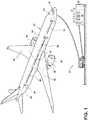
- FIG. 1 schematically depicts one aspect of the present disclosure as an exemplary environment where the diagnostic and prognostic model herein described can be effectively used.
- An aircraft 10 is shown during a maintenance operation transmitting data, ultimately, to a data operations center 26 that will execute aspects of the present disclosure including the diagnostic and prognostic model presented herein.
- the aircraft 10 includes one or more complex systems that include a multitude of parts therein, the complex systems relating to various aspects of the aircraft.
- the aircraft includes one or more propulsion engines 12, a fuselage 14 with a cockpit 16 positioned in the fuselage 14, where the one or more propulsion engines 12 is coupled to the fuselage 14 directly or, as shown, by way of wing assemblies 18 extending outward from the fuselage 14.
- each of the engines 12, the fuselage 14 including the cockpit 16, and the wing assemblies 18 have many, many individual physical components, such as motors, fans, conduits, structural members, wiring harnesses, switches, relays, electrical junctions, sensors, displays, panels, and the like. While a commercial aircraft has been illustrated, it is contemplated that aspects of the present disclosure can be used in any type of complex system, including, for example, power plants, ships, trains, buildings, space craft, and aircraft different than aspects of the present disclosure, including fixed-wing, rotating-wing, rocket, personal aircraft, etc.
- the complex of systems in the aircraft can include a plurality of aircraft subsystems 20 that enable proper operation of the aircraft 10 and can include one or more computers or controllers 22, which can be operably coupled to the plurality of aircraft subsystems 20 to control their operation. While only a single controller 22 has been illustrated, it is contemplated that any number of controllers 22 can be included in the aircraft 10. In such an instance, the controller 22 can also be connected with other controllers of the aircraft 10.
- the controller 22 can include or be associated with any suitable number of individual microprocessors, power supplies, storage devices, interface cards, auto flight systems, flight management computers, and other standard components.
- an aircraft subsystem 20 can include sensor components for observing, gathering and transferring data related to the operational life of the parts of the system. The transferred data can then be communicated to the one or more controllers 22.
- the sensor components will be proximate to or in some way coupled to any of the aircraft parts to observe and generate the data to be transmitted to the one or more controllers 22.
- the data can include, for example, operation measurements, environmental measurements, flight path, altitude, or the amount of time or number of cycles that a given aircraft part is subject to various levels of pressure, temperature, or strain. Such data may termed "operational data" related to a given component of the aircraft.
- the controller 22 can be communicably coupled to one or more communication links to transmit data to and from the aircraft 10.
- the communication links can be wireless communication links and can be any variety of communication mechanism capable of wirelessly linking with other systems and devices and can include, but is not limited to, packet radio, satellite uplink and/or downlink, Wireless Fidelity (WiFi), WiMax, Bluetooth, ZigBee, 3G wireless signal, code division multiple access (CDMA) wireless signal, global system for mobile communication (GSM), 4G wireless signal, 5G wireless signal, long term evolution (LTE) signal, Ethernet, or any combinations thereof.
- packet radio satellite uplink and/or downlink
- WiFi Wireless Fidelity
- WiMax Wireless Fidelity
- Bluetooth ZigBee
- 3G wireless signal code division multiple access (CDMA) wireless signal
- GSM global system for mobile communication
- 4G wireless signal 5G wireless signal
- LTE long term evolution
- the communication links can include one or more radios including voice, aircraft communications addressing and reporting system (ACARS)-analog, ACARS-digital, satellite communication (SATCOM), cellular, etc.
- ACARS aircraft communications addressing and reporting system
- SATCOM satellite communication
- the communication links can allow for communication with maintenance personnel via, for example a maintenance vehicle 24, ground controllers or data operations center 26 at a ground-based station or with non-ground stations such as satellite (not shown).
- the transmitted data from the aircraft 10 is communicated to the data operations center 26 via a maintenance vehicle 24, it will be understood that the aircraft 10 can communicate directly with the data operations center 26 utilizing the communication links.
- a data controller 28 can receive, store, or process the transmitted data from the aircraft 10. While the data transferred the aircraft 10 will include operational data from sensors proximate to or coupled with the monitored parts, the data will also include environmental data such as weather data, geographical location, satellite images, and any other data or information or knowledge about the environment in which the part has been operated. Such data may termed "environmental data" related to the given component of the aircraft.
- the transferred operational or environmental data from the aircraft 10 can be inferred data or data that is not measured directly but can be inferred using one or more measured data either in combination of understanding the physics of the part or the system or not.
- some temperatures inside an engine cannot be directly measured but can be inferred by knowing engine cycle physics and other directly measured parameters that can include environmental parameters, engine sensor parameters, or design specific parameters.
- Visual inspection can include eyesight observation by inspectors, as well as instrumental observation with the aid of electro-optical equipment such as a borescope or the aid of radiometric or spectrographic systems, and image collectors.
- Such observation data can be enhanced with image enhancement and well established predictive algorithms. Modeling of the observational data with processing-intensive routines such as provided by finite element analysis can further enhance the observational data.
- a crack 34 in the airfoil blade 30 may be observed during a visual inspection.
- the crack 34 can have a crack length 36 that illustrates, by way of non-limiting example, a one dimensional measurement of the crack 34.
- the crack length 36 can be measured as the length of a relatively linear line connecting one end of the crack to another end. It is also contemplated that the crack length 36 can be the length of a non-linear line that follows the contours of the crack from one end to the other. It is further contemplated that the crack length 36 can be measured as the number of the cooling holes 32 affected by the crack 34.
- the crack length 36 can be calculated using known methods such as, but not limited to, determining the crack length 36 using a multidimensional method that follows the shape or perimeter of the crack 34.
- thermal barrier coating loss 40 on the airfoil blade 30 with a length 42 and a width 44.
- the length 42 can be the measurement of the most extended dimension and the width 44 can be orthogonal to the length 42 representing the greatest extension in a second dimension.
- the area of thermal barrier coating loss 40 can be measured as a number of pixels, or calculated using other known area dimensional estimating techniques.
- the crack length 36, the area of thermal barrier coating loss 40, or the area of oxidation 46 are non-limiting examples of observational data obtained during a physical inspection of the airfoil blade 30.
- the observational data from the physical inspection will be communicated to the data operations center 26. It will be understood that the physical inspection can include a visual inspection and that there will be multiple physical or visual inspections for a single aircraft as well as multiple aircraft for the airfoil blade 30. The data therefrom can be termed "observed distress data.”
- FIG. 3 illustrates a data controller 28 that might be used to effect the model or method of predicting distress for the exemplary airfoil blade 30.
- the data controller 28 can be provided with a memory 50, a distress rank module 52, a predictive module 54, and a comparative module 56.
- the data controller 28 can couple to a user interface 58.
- the user interface 58 can be used to enter data into the data controller 28 or to provide information to a user upon request or in response to the entered data. Information that can be provided via the user interface 58 is further discussed with respect to FIG. 4 .
- a display screen 59 can be included in communication with or coupled to the user interface 58.
- the display screen 59 can be any suitable display screen such as a liquid crystal display (LCD) screen, a plasma screen, a smart glass screen, or any other type of screen or medium on which information can be displayed.
- LCD liquid crystal display
- the data controller 28 can couple to one or more wireless communication devices 62 for sending and receiving information, such as, but not limited to, operational data, environmental data and/or observed distress data in the data operations center 26. It is contemplated that the one or more wireless communication devices 62 are capable of establishing a communication link with the aircraft 10, the maintenance vehicle, or other device capable of communicating information.
- the wireless communication links and can be any variety of communication mechanism capable of wirelessly linking with other systems and devices and can include, but is not limited to, packet radio, satellite uplink and/or downlink, Wireless Fidelity (WiFi), WiMax, Bluetooth, ZigBee, 3G wireless signal, code division multiple access (CDMA) wireless signal, global system for mobile communication (GSM), 4G wireless signal, 5G wireless signal, long term evolution (LTE) signal, Ethernet, or any combinations thereof. It will also be understood that the particular type or mode of wireless communication is not critical to aspects of the present disclosure, and later-developed wireless networks are certainly contemplated as within the scope of the present disclosure.
- the memory 50 can include or communicate with a database 60.
- the database 60 can store sets of operational data, environmental data, design specific data and/or observed distress data received from the data operations center 26.
- the database 60 can be more than one database accessible to or in communication with the data controller 28.
- Design specific data can include, by way of non-liming example, information related to manufacturing location, time, materials, or technique.
- the distress rank module 52 uses a set of observed distress data to determine a distress rank output, which, in the present illustration, would be a distress rank output related to the airfoil blade 30.
- the predictive module 54 obtains a set of environmental data or a set of operational data or related to the physical component, which, in this case is the airfoil blade 30. It formulates a kernel using parameters of the environmental data and/or the operational data and a cumulative damage model (CDM) related to the physical component. It further generates a predictive model based on the kernel that provides a distress output related to the physical component, which, in this case is the airfoil blade 30. It is contemplated that the distress rank module 52 or the predictive module 54 can communicate with the database 60 to obtain additional information when determining the distress rank output or the distress output for the physical component.
- CDM cumulative damage model
- a comparative module 56 communicates with the distress rank module 52 and the predictive module 54 to obtain the distress rank output and the distress output for the physical component.
- the comparative module 56 compares a value of the distress rank output to a value of the distress output and communicates any difference back to the predictive module 54. Additionally or alternatively, the comparative module 56 can communicate any difference to the distress rank module 52 or user interface 58.
- the data controller 28 can in fact be in distributed computing environments where tasks are performed by local and remote processing devices that are linked (either by hardwired links, wireless links, or by a combination of hardwired or wireless links) through a communication network.
- program modules can be located in both local and remote memory storage devices.
- FIG. 4 illustrates a method 100 of predicting distress on any physical component, conducted using the controller 28.
- a first set of distress data for the physical component is obtained.
- the first set of distress data will preferably include 20 data points or more.
- a distress rank of the physical component is determined based on first set of distress data.
- the distress rank module 52 can output the distress rank to the comparative module 56.
- a set of environmental data related to the physical component or a set of operational data related to the physical component or both are obtained, for example, from the database 60, or directly from the data operations center 26.
- a kernel can be formulated at step 108 using parameters from the set of environmental data, the set of operational data, or the cumulative damage model related to the physical component.
- the predictive module 54 can use additional information from the database 60 to formulate the kernel.
- the set of design specific data related to the physical component might be include as a parameter in formulating the kernel.
- the set of design specific parameters can be obtained, for example, from the database 60. It is contemplated that kernel can be formulated using a variety of parameters related to the physical component.
- a predictive model is generated based on the kernel that provides a distress output related to the physical component.
- the distress output is transmitted to the comparative module 56.
- the distress output is compared to the distress rank at step 112.
- the comparative module 56 can compare the distress output to the distress rank to output a difference.
- the predictive model is tuned at step 116 by adjusting at least one parameter of the kernel, which is then reformulated at step 108, generating an updated predictive model at step 110.
- the distress output of the updated predictive model is then compared again to the distress rank at step 112. If further adjustments are available, then further tuning is done, repeating steps 108 - 116 until adjustments to the parameters are no longer available or needed to place the difference within the threshold. If, at step 118, the difference is within the threshold or satisfies the threshold, the updated predictive model can be applied to the physical component at step 120 to predict distress on the physical component.
- the method 100 can be restarted at step 102 with a different or larger set of distress data and/or a different or larger set of environmental or operational data.
- a different or larger set of distress data can include a second set of distress data where tuning the predictive model can be based on the first set of distress data, the second set of distress data, or a combination of the first and second sets of distress data.
- the second set of distress data can include 5 data points or more. It is contemplated that any number of sets of distress data can be used to tune the predictive model. It is further contemplated that any combination of distress data from the one or more sets of distress data can be used to tune the predictive model.
- the kernel can be reformulated using different combinations of parameters or different CDM models.
- the threshold can be determined using a variety of known methods and often includes specially developed algorithms which can vary between objects.
- the threshold can be minimum coefficient of determination, or "R squared" value.
- the threshold can be an "R squared” value of 0.6 or more.
- the "R squared” value can be calculated, indicating the comparison between the graphical model and the one or more distress rank output(s). The calculated "R squared” value can be compared to the threshold. If at 118, the "R squared” value is greater than or equal to 0.6 then the updated predictive model can be applied to the physical component at step 120. However, if at 118, the "R squared" is less than 0.6, then the method 100 can be restarted at step 102. It is further contemplated that additional algorithms can be executed to assist in determining what aspects of the data, parameters, or models can be adjusted prior to the method 100 restarting at 102.
- the distress data will include observations and data about the crack length 36 and the area of thermal barrier coating loss 40. Additionally, the distress data can be obtained from multiple aircraft.
- Distress ranking of physical components is known in the art and often includes specially developed algorithms which can vary between objects, as can the observed distress data used in the algorithms. It is further contemplated that the distress rank module 52 can obtain additional information about the object or previous observational data from the database 60 when calculating the distress rank of an object such as, but not limited to a location of previous repair or replacement, age of the one or more objects, or trend data gathered from similar objects. However, for illustrative purposes, we will consider distress rank as a causation based on crack length and area of thermal barrier coating loss.
- the distress rank module 52 can obtain the distress data that includes the dimension of 9.75 square inches experiencing thermal barrier coating loss and assign, for example, a distress rank of 2.
- the distress rank module 52 also considers distress data that includes the dimension of 2.25 inches of cracking and assigns, for example, a rank of 4.
- the distress rank module 52 can then combine them to determine a distress rank output of 6 for the airfoil blade 30. If the distress data was obtained from multiple aircraft, a distress rank output for each airfoil blade in which data was collected can be communicated to the distress rank module 52 as a set of distress data.
- the combination of rank 2 and rank 4 be distress rank 6, resulting in a distress rank output of 6 from the distress rank module 52 at step 104.
- the combination of rank 2 and rank 4 can result in a distress rank output having a different value if a weighting is assigned to different observed distress data.
- the distress rank 6 be the output to the comparative module 56.
- the set of environmental data, the set of operational data, or the set of design specific data related to the airfoil blade 30 can be obtained by the predictive module 54 using the transmitted data from the aircraft 10 or the additional information from the database 60.
- the set of environmental data, the set of operational data, or the set of design specific data can be arranged or organized as parameters by the predictive module 54. If the distress data was obtained from multiple aircraft, step 106 can obtain the set of environmental data, the set of operational data, or the set of design specific data related to each airfoil blade.
- the transmitted data from the aircraft 10 to the predictive module 54 can be used to develop a cumulative damage model (CDM) related to the airfoil blade 30.
- CDM can contribute to determining the physical phenomenon driving distress of the airfoil blade 30 using a physics-based model of the related to the airfoil blade's 30 lifecycle.
- the CDM can also be used as a parameter.
- the kernel related to the airfoil blade 30 can be formulated by the predictive module 54.
- the kernel can be formulated using parameters that can include the set of environmental data, the set of operational data, the set of design specific data, or the CDM.
- the kernel can be used to generate a predictive model that can provide the distress output for the airfoil blade 30. It is contemplated that in addition to the transferred data from the aircraft 10, additional data from the database 60 can be used to develop the CDM or formulate the kernel.
- the predictive model related to the airfoil blade is used by the predictive module 54 to provide the distress output to the comparative module 56.
- the predictive module 54 can provide the distress output to the comparative module 56 for each airfoil blade.
- the comparative module 56 compares the distress output value (here, 250) to the distress rank value (here, 6); calculating a difference. It is contemplated that the distress output is scaled before comparison to the distress rank. By way of non-liming example, let the scale be one-fiftieth. Therefore, the value 250 can be scaled to the distress output of 5. The comparative module 56 then calculates the difference between 5 and 6. If the distress data was obtained from multiple airfoil blades, the comparative module 56 can compare the distress output to the distress rank for each airfoil blade.
- the updated prediction model for the airfoil blade 30 provides the distress output 290; which converts to 5.8. Since 5.8 is closer to 6 than 5, the added with to the environmental parameter in the kernel is maintained. If no other change in parameters decreases the difference between the distress output and the distress rank, the difference is then assessed at 118. Let a difference of 0.2 be considered within the threshold. The updated predictive model is ready to be used for the airfoil blade 30.
- the predictive model can prepare a display illustrating the predicted distress on the airfoil blade 30 (or other physical component).
- the display can include graph that can, for example, illustrate damage or distress rank verses cycles.
- the damage or distress rank verses cycles graph can be used to determine an inspection schedule or a maintenance schedule for the airfoil blade 30 (or other physical component).
- the updated predictive model can be used to develop design changes to the airfoil blade 30.
- the aspects of the present disclosure include obtaining data for formulating a distress rank and a prediction model, wherein the prediction model can be improved using the distress data.
- the technical effect is that the aspects described herein enable tuning of a predictive model that can be applied to a physical component.
- One advantage that can be realized is superior prediction capabilities for physical components as compared with conventional systems.
- the superior prediction capabilities can improve inspection schedules or maintenance schedules.
- the superior prediction capabilities can reduce unplanned operational disruptions.
- Another advantage to increased prediction capabilities is the ability to predict distress and lifetime of parts still in the design phase. This will improve future designs.
Landscapes
- Engineering & Computer Science (AREA)
- Physics & Mathematics (AREA)
- General Physics & Mathematics (AREA)
- Automation & Control Theory (AREA)
- Evolutionary Computation (AREA)
- Theoretical Computer Science (AREA)
- Artificial Intelligence (AREA)
- Manufacturing & Machinery (AREA)
- Transportation (AREA)
- Aviation & Aerospace Engineering (AREA)
- Mathematical Physics (AREA)
- General Engineering & Computer Science (AREA)
- Computer Hardware Design (AREA)
- Health & Medical Sciences (AREA)
- Geometry (AREA)
- Quality & Reliability (AREA)
- General Health & Medical Sciences (AREA)
- Immunology (AREA)
- Pathology (AREA)
- Life Sciences & Earth Sciences (AREA)
- Biochemistry (AREA)
- Analytical Chemistry (AREA)
- Chemical & Material Sciences (AREA)
- Computer Vision & Pattern Recognition (AREA)
- Medical Informatics (AREA)
- Software Systems (AREA)
- Testing And Monitoring For Control Systems (AREA)
- Management, Administration, Business Operations System, And Electronic Commerce (AREA)
- Testing Of Devices, Machine Parts, Or Other Structures Thereof (AREA)
Abstract
Description
- The disclosure relates to a method and apparatus for predicting distress on a physical component by determining a distress rank for the component and using the distress rank to generate a prediction model.
- Evaluating diagnostics and prognostics of physical parts of a machine is useful for scheduling maintenance or repair or replacement of the parts, particularly where the parts operate in high stress environments such as the components of aircraft engines. Dependable evaluation within complex systems permits operators or maintenance personnel to reliably and predictably inspect and repair the components, as well as maintain high operational efficiency and quality of the components. For example, with respect to the aircraft engine, early detection of hardware distress is vital to preventing in-flight shutdowns, unplanned engine removals, or secondary hardware damage. With earlier accurate prediction, system planners can more readily schedule maintenance and replace hardware without the need for a full system overhaul.
- The present disclosure relates to a method of predicting distress on a physical component that includes: a. obtaining a first set of distress data for a physical component, b. determining a distress rank of the physical component based on first set of distress data, c. obtaining at least one of a set of environmental data and a set of operational data related to the physical component, d. formulating a kernel using parameters of at least one of the set of environmental data and the set of operational data and a cumulative damage model related to the physical component, e. generating a predictive model based on the kernel that provides a distress output related to the physical component, f. comparing the distress output to the distress rank, g. tuning the predictive model based on the comparing the distress output to the distress rank by adjusting at least one parameter of the kernel and generating an updated predictive model, h. repeating steps d-g until no more adjustments to the at least one parameter can effectively be made; and i. if the difference is within the threshold, applying the updated predictive model to the physical component to predict distress on the physical component, or if the difference is outside the threshold, restarting the method at step a.
- The present disclosure relates to a system for predicting distress on a physical component, where the systems includes a memory storing distress data, environmental data and operational data related to a physical component, a distress rank module coupled to the memory configured to access a first set of distress data for the physical component, and to determine a distress rank of the physical component based on the first set of distress data, a predictive module coupled to the distress rank module and to the memory, configured to access at least one of a set of environmental data or a set of operational data related to the physical component, formulate a kernel using parameters of at least one of a set of environmental data and a set of operational data and a cumulative damage model related to the physical component, and generate a predictive model based on the kernel that provides a distress output related to the physical component, and a controller coupled to the memory, the distress rank module, and the cumulative damage module, configured to compare the distress output to the distress rank, tune the predictive model by adjusting at least one parameter of the kernel and generate an updated predictive model if a difference between the distress output and the distress rank of the physical component exceeds a predetermined threshold, repeat the comparing and tuning until no more adjustments to the at least one parameter can effectively be made, and apply the updated predictive model to the physical component to predict distress on the physical component if the difference is within the threshold.
- In the drawings:
-
FIG. 1 is a perspective view of an aircraft and data controller -
FIG. 2 is a perspective view of an airfoil blade that can be included in an aircraft engine of the aircraft ofFIG. 1 . -
FIG. 3 is schematic view of the data controller ofFIG. 1 . -
FIG. 4 is a flow chart illustrating a method for predicting distress. - Aspects of the disclosure described herein are directed to a method and apparatus for predicting distress on a physical component, as well as inspecting and developing a model for determining damage on the physical component and predicting distress based upon such analysis. For purposes of illustration, the present disclosure will be described with respect to a component for an aircraft turbine engine. It will be understood, however, that aspects of the disclosure described herein are not so limited and can have general applicability within an engine as well as in non-aircraft applications, such as other mobile applications and non-mobile industrial, commercial, and residential applications, and need not be limited to the aircraft or aircraft engine realm.
- It will be understood that details of environments that can implement aspects of the present disclosure are set forth in order to provide a thorough understanding of the technology described herein. It will be evident to one skilled in the art, however, that aspects of the present disclosure can be practiced without these specific details. The drawings illustrate certain details of specific aspects of the present disclosure that implement a module or method, or computer program product described herein. However, the drawings should not be construed as imposing any limitations that can be present in the drawings. The method and computer program product can be provided on any machine-readable media for accomplishing their operations. Aspects of the present disclosure can be implemented using an existing computer processor, or by a special purpose computer processor incorporated for this or another purpose, or by a hardwired system.
- As used herein, the term "forward" or "upstream" refers to moving in a direction toward the engine inlet, or a component being relatively closer to the engine inlet as compared to another component. The term "aft" or "downstream" used in conjunction with "forward" or "upstream" refers to a direction toward the rear or outlet of the engine or being relatively closer to the engine outlet as compared to another component. Additionally, as used herein, the terms "radial" or "radially" refer to a dimension extending between a center longitudinal axis of the engine and an outer engine circumference. Furthermore, as used herein, the term "set" or a "set" of elements can be any number of elements, including only one.
- All directional references (e.g., radial, axial, proximal, distal, upper, lower, upward, downward, left, right, lateral, front, back, top, bottom, above, below, vertical, horizontal, clockwise, counterclockwise, upstream, downstream, forward, aft, etc.) are only used for identification purposes to aid the reader's understanding of the present disclosure, and do not create limitations, particularly as to the position, orientation, or use of aspects of the disclosure described herein. Connection references (e.g., attached, coupled, connected, and joined) are to be construed broadly and can include intermediate members between a collection of elements and relative movement between elements unless otherwise indicated. As such, connection references do not necessarily infer that two elements are directly connected and in fixed relation to one another. The exemplary drawings are for purposes of illustration only and the dimensions, positions, order and relative sizes reflected in the drawings attached hereto can vary.
- As used herein, a "system" or a "controller module" can include at least one processor and memory. Non-limiting examples of the memory can include Random Access Memory (RAM), Read-Only Memory (ROM), flash memory, or one or more different types of portable electronic memory, such as discs, Digital Versatile Discs (DVDs), Compact Disc Read-only Memory (CD-ROMs), etc., or any suitable combination of these types of memory. The processor can be configured to run any suitable programs or executable instructions designed to carry out various methods, functionality, processing tasks, calculations, or the like, to enable or achieve the technical operations or operations described herein. The program can include a computer program product that can include machine-readable media for carrying or having machine-executable instructions or data structures stored thereon. Such machine-readable media can be any available media, which can be accessed by a general purpose or special purpose computer or other machine with a processor. Generally, such a computer program can include routines, programs, objects, components, data structures, algorithms, etc., that have the technical effect of performing particular tasks or implement particular abstract data types.
- In another non-limiting example, a control module can include comparing a first value with a second value, and operating or controlling operations of additional components based on the satisfying of that comparison. For example, when a sensed, measured, or provided value is compared with another value, including a stored or predetermined value, the satisfaction of that comparison can result in actions, functions, or operations controllable by the controller module. As used, the term "satisfies" or "satisfaction" of the comparison is used herein to mean that the first value satisfies the second value, such as being equal to or less than the second value, or being within the value range of the second value. It will be understood that such a determination can easily be altered to be satisfied by a positive/negative comparison or a true/false comparison. Example comparisons can include comparing a sensed or measured value to a threshold value or threshold value range.
-
FIG. 1 schematically depicts one aspect of the present disclosure as an exemplary environment where the diagnostic and prognostic model herein described can be effectively used. Anaircraft 10 is shown during a maintenance operation transmitting data, ultimately, to adata operations center 26 that will execute aspects of the present disclosure including the diagnostic and prognostic model presented herein. Theaircraft 10 includes one or more complex systems that include a multitude of parts therein, the complex systems relating to various aspects of the aircraft. The aircraft includes one or more propulsion engines 12, afuselage 14 with acockpit 16 positioned in thefuselage 14, where the one or more propulsion engines 12 is coupled to thefuselage 14 directly or, as shown, by way ofwing assemblies 18 extending outward from thefuselage 14. It will be appreciated that each of the engines 12, thefuselage 14 including thecockpit 16, and thewing assemblies 18 have many, many individual physical components, such as motors, fans, conduits, structural members, wiring harnesses, switches, relays, electrical junctions, sensors, displays, panels, and the like. While a commercial aircraft has been illustrated, it is contemplated that aspects of the present disclosure can be used in any type of complex system, including, for example, power plants, ships, trains, buildings, space craft, and aircraft different than aspects of the present disclosure, including fixed-wing, rotating-wing, rocket, personal aircraft, etc. - The complex of systems in the aircraft can include a plurality of
aircraft subsystems 20 that enable proper operation of theaircraft 10 and can include one or more computers orcontrollers 22, which can be operably coupled to the plurality ofaircraft subsystems 20 to control their operation. While only asingle controller 22 has been illustrated, it is contemplated that any number ofcontrollers 22 can be included in theaircraft 10. In such an instance, thecontroller 22 can also be connected with other controllers of theaircraft 10. Thecontroller 22 can include or be associated with any suitable number of individual microprocessors, power supplies, storage devices, interface cards, auto flight systems, flight management computers, and other standard components. In addition to components for the proper operation of the aircraft, anaircraft subsystem 20 can include sensor components for observing, gathering and transferring data related to the operational life of the parts of the system. The transferred data can then be communicated to the one ormore controllers 22. - The sensor components will be proximate to or in some way coupled to any of the aircraft parts to observe and generate the data to be transmitted to the one or
more controllers 22. The data can include, for example, operation measurements, environmental measurements, flight path, altitude, or the amount of time or number of cycles that a given aircraft part is subject to various levels of pressure, temperature, or strain. Such data may termed "operational data" related to a given component of the aircraft. - The
controller 22 can be communicably coupled to one or more communication links to transmit data to and from theaircraft 10. It is contemplated that the communication links can be wireless communication links and can be any variety of communication mechanism capable of wirelessly linking with other systems and devices and can include, but is not limited to, packet radio, satellite uplink and/or downlink, Wireless Fidelity (WiFi), WiMax, Bluetooth, ZigBee, 3G wireless signal, code division multiple access (CDMA) wireless signal, global system for mobile communication (GSM), 4G wireless signal, 5G wireless signal, long term evolution (LTE) signal, Ethernet, or any combinations thereof. It will also be understood that the particular type or mode of wireless communication is not critical to aspects of the present disclosure, and later-developed wireless networks are certainly contemplated as within the scope of the present disclosure. Further, the communication links can include one or more radios including voice, aircraft communications addressing and reporting system (ACARS)-analog, ACARS-digital, satellite communication (SATCOM), cellular, etc. The communication links can allow for communication with maintenance personnel via, for example amaintenance vehicle 24, ground controllers ordata operations center 26 at a ground-based station or with non-ground stations such as satellite (not shown). - Further, while it has been illustrated that the transmitted data from the
aircraft 10 is communicated to thedata operations center 26 via amaintenance vehicle 24, it will be understood that theaircraft 10 can communicate directly with thedata operations center 26 utilizing the communication links. At thedata operations center 26, adata controller 28 can receive, store, or process the transmitted data from theaircraft 10. While the data transferred theaircraft 10 will include operational data from sensors proximate to or coupled with the monitored parts, the data will also include environmental data such as weather data, geographical location, satellite images, and any other data or information or knowledge about the environment in which the part has been operated. Such data may termed "environmental data" related to the given component of the aircraft. - In addition to the above, the transferred operational or environmental data from the
aircraft 10 can be inferred data or data that is not measured directly but can be inferred using one or more measured data either in combination of understanding the physics of the part or the system or not. In one non-limiting example, some temperatures inside an engine cannot be directly measured but can be inferred by knowing engine cycle physics and other directly measured parameters that can include environmental parameters, engine sensor parameters, or design specific parameters. - Consider, by way of non-limiting example, that one might want to predict the operational life of an
airfoil blade 30 located within the one or more propulsion engines 12 of the aircraft. It will be understood that operational data and environmental data for theairfoil blade 30 in multiple aircraft will have been collected by thedata operations center 26. - In addition to the operational and environmental data, there will have been periodic visual inspections of the
airfoil blade 30 in multiple aircraft, for example, during routine maintenance operations. Visual inspection can include eyesight observation by inspectors, as well as instrumental observation with the aid of electro-optical equipment such as a borescope or the aid of radiometric or spectrographic systems, and image collectors. Such observation data can be enhanced with image enhancement and well established predictive algorithms. Modeling of the observational data with processing-intensive routines such as provided by finite element analysis can further enhance the observational data. - As illustrated in
FIG. 2 , by way of example, consider a visual inspection of theairfoil blade 30 which includes cooling holes 32. Acrack 34 in theairfoil blade 30 may be observed during a visual inspection. Thecrack 34 can have acrack length 36 that illustrates, by way of non-limiting example, a one dimensional measurement of thecrack 34. Thecrack length 36 can be measured as the length of a relatively linear line connecting one end of the crack to another end. It is also contemplated that thecrack length 36 can be the length of a non-linear line that follows the contours of the crack from one end to the other. It is further contemplated that thecrack length 36 can be measured as the number of the cooling holes 32 affected by thecrack 34. - Alternatively, it is contemplated that the
crack length 36 can be calculated using known methods such as, but not limited to, determining thecrack length 36 using a multidimensional method that follows the shape or perimeter of thecrack 34. - There can also be observed an area of thermal
barrier coating loss 40 on theairfoil blade 30 with alength 42 and awidth 44. Thelength 42 can be the measurement of the most extended dimension and thewidth 44 can be orthogonal to thelength 42 representing the greatest extension in a second dimension. Alternatively, the area of thermalbarrier coating loss 40 can be measured as a number of pixels, or calculated using other known area dimensional estimating techniques. - By way of further non-limiting example, there can be an area of
oxidation 46 on theairfoil blade 30. However measured, thecrack length 36, the area of thermalbarrier coating loss 40, or the area ofoxidation 46 are non-limiting examples of observational data obtained during a physical inspection of theairfoil blade 30. The observational data from the physical inspection will be communicated to thedata operations center 26. It will be understood that the physical inspection can include a visual inspection and that there will be multiple physical or visual inspections for a single aircraft as well as multiple aircraft for theairfoil blade 30. The data therefrom can be termed "observed distress data." -
FIG. 3 illustrates adata controller 28 that might be used to effect the model or method of predicting distress for theexemplary airfoil blade 30. Thedata controller 28 can be provided with amemory 50, adistress rank module 52, apredictive module 54, and acomparative module 56. Thedata controller 28 can couple to auser interface 58. Theuser interface 58 can be used to enter data into thedata controller 28 or to provide information to a user upon request or in response to the entered data. Information that can be provided via theuser interface 58 is further discussed with respect toFIG. 4 . Adisplay screen 59 can be included in communication with or coupled to theuser interface 58. Thedisplay screen 59 can be any suitable display screen such as a liquid crystal display (LCD) screen, a plasma screen, a smart glass screen, or any other type of screen or medium on which information can be displayed. - Optionally, the
data controller 28 can couple to one or morewireless communication devices 62 for sending and receiving information, such as, but not limited to, operational data, environmental data and/or observed distress data in thedata operations center 26. It is contemplated that the one or morewireless communication devices 62 are capable of establishing a communication link with theaircraft 10, the maintenance vehicle, or other device capable of communicating information. The wireless communication links and can be any variety of communication mechanism capable of wirelessly linking with other systems and devices and can include, but is not limited to, packet radio, satellite uplink and/or downlink, Wireless Fidelity (WiFi), WiMax, Bluetooth, ZigBee, 3G wireless signal, code division multiple access (CDMA) wireless signal, global system for mobile communication (GSM), 4G wireless signal, 5G wireless signal, long term evolution (LTE) signal, Ethernet, or any combinations thereof. It will also be understood that the particular type or mode of wireless communication is not critical to aspects of the present disclosure, and later-developed wireless networks are certainly contemplated as within the scope of the present disclosure. - The
memory 50 can include or communicate with adatabase 60. For example, thedatabase 60 can store sets of operational data, environmental data, design specific data and/or observed distress data received from thedata operations center 26. Thedatabase 60 can be more than one database accessible to or in communication with thedata controller 28. Design specific data can include, by way of non-liming example, information related to manufacturing location, time, materials, or technique. - The
distress rank module 52 uses a set of observed distress data to determine a distress rank output, which, in the present illustration, would be a distress rank output related to theairfoil blade 30. Thepredictive module 54 obtains a set of environmental data or a set of operational data or related to the physical component, which, in this case is theairfoil blade 30. It formulates a kernel using parameters of the environmental data and/or the operational data and a cumulative damage model (CDM) related to the physical component. It further generates a predictive model based on the kernel that provides a distress output related to the physical component, which, in this case is theairfoil blade 30. It is contemplated that thedistress rank module 52 or thepredictive module 54 can communicate with thedatabase 60 to obtain additional information when determining the distress rank output or the distress output for the physical component. - A
comparative module 56 communicates with thedistress rank module 52 and thepredictive module 54 to obtain the distress rank output and the distress output for the physical component. Thecomparative module 56 compares a value of the distress rank output to a value of the distress output and communicates any difference back to thepredictive module 54. Additionally or alternatively, thecomparative module 56 can communicate any difference to thedistress rank module 52 oruser interface 58. - It is contemplated that the
data controller 28 can in fact be in distributed computing environments where tasks are performed by local and remote processing devices that are linked (either by hardwired links, wireless links, or by a combination of hardwired or wireless links) through a communication network. In a distributed computing environment, program modules can be located in both local and remote memory storage devices. -
FIG. 4 illustrates amethod 100 of predicting distress on any physical component, conducted using thecontroller 28. Atstep 102 of themethod 100, a first set of distress data for the physical component is obtained. The first set of distress data will preferably include 20 data points or more. Atstep 104, a distress rank of the physical component is determined based on first set of distress data. Thedistress rank module 52 can output the distress rank to thecomparative module 56. - At
step 106, a set of environmental data related to the physical component or a set of operational data related to the physical component or both are obtained, for example, from thedatabase 60, or directly from thedata operations center 26. - A kernel can be formulated at
step 108 using parameters from the set of environmental data, the set of operational data, or the cumulative damage model related to the physical component. Thepredictive module 54 can use additional information from thedatabase 60 to formulate the kernel. For example, the set of design specific data related to the physical component might be include as a parameter in formulating the kernel. The set of design specific parameters can be obtained, for example, from thedatabase 60. It is contemplated that kernel can be formulated using a variety of parameters related to the physical component. - At
step 110, a predictive model is generated based on the kernel that provides a distress output related to the physical component. The distress output is transmitted to thecomparative module 56. - The distress output is compared to the distress rank at
step 112. Thecomparative module 56 can compare the distress output to the distress rank to output a difference. - At
step 114, if adjustments to the parameters are available, the predictive model is tuned atstep 116 by adjusting at least one parameter of the kernel, which is then reformulated atstep 108, generating an updated predictive model atstep 110. The distress output of the updated predictive model is then compared again to the distress rank atstep 112. If further adjustments are available, then further tuning is done, repeating steps 108 - 116 until adjustments to the parameters are no longer available or needed to place the difference within the threshold. If, atstep 118, the difference is within the threshold or satisfies the threshold, the updated predictive model can be applied to the physical component atstep 120 to predict distress on the physical component. However, if at 118, the difference remains outside the threshold or does not satisfies the threshold, themethod 100 can be restarted atstep 102 with a different or larger set of distress data and/or a different or larger set of environmental or operational data. An example of a different or larger set of distress data can include a second set of distress data where tuning the predictive model can be based on the first set of distress data, the second set of distress data, or a combination of the first and second sets of distress data. By way of non-limiting example, the second set of distress data can include 5 data points or more. It is contemplated that any number of sets of distress data can be used to tune the predictive model. It is further contemplated that any combination of distress data from the one or more sets of distress data can be used to tune the predictive model. Optionally, when themethod 100 restarts at 102, the kernel can be reformulated using different combinations of parameters or different CDM models. - The threshold can be determined using a variety of known methods and often includes specially developed algorithms which can vary between objects. By way of non-limiting example, the threshold can be minimum coefficient of determination, or "R squared" value.
- It is contemplated that the threshold can be an "R squared" value of 0.6 or more. Consider the distress output from the updated predictive model as a graphical model that can be applied to one or more distress rank output(s) from the
distress rank module 52. Using known methods, the "R squared" value can be calculated, indicating the comparison between the graphical model and the one or more distress rank output(s). The calculated "R squared" value can be compared to the threshold. If at 118, the "R squared" value is greater than or equal to 0.6 then the updated predictive model can be applied to the physical component atstep 120. However, if at 118, the "R squared" is less than 0.6, then themethod 100 can be restarted atstep 102. It is further contemplated that additional algorithms can be executed to assist in determining what aspects of the data, parameters, or models can be adjusted prior to themethod 100 restarting at 102. - Consider now the physical component to be the
aforementioned airfoil blade 30. The distress data will include observations and data about thecrack length 36 and the area of thermalbarrier coating loss 40. Additionally, the distress data can be obtained from multiple aircraft. - Distress ranking of physical components is known in the art and often includes specially developed algorithms which can vary between objects, as can the observed distress data used in the algorithms. It is further contemplated that the
distress rank module 52 can obtain additional information about the object or previous observational data from thedatabase 60 when calculating the distress rank of an object such as, but not limited to a location of previous repair or replacement, age of the one or more objects, or trend data gathered from similar objects. However, for illustrative purposes, we will consider distress rank as a causation based on crack length and area of thermal barrier coating loss. - Consider the
crack length 36 of thecrack 34 to be a length 2.25 inches and the area of thermalbarrier coating loss 40 have thelength 42 of 3.00 inches and thewidth 44 of 3.25 inches. Therefore the area of thermalbarrier coating loss 40 is 9.75 square inches. - By way of non-limiting example, at
step 102 thedistress rank module 52 can obtain the distress data that includes the dimension of 9.75 square inches experiencing thermal barrier coating loss and assign, for example, a distress rank of 2. Thedistress rank module 52 also considers distress data that includes the dimension of 2.25 inches of cracking and assigns, for example, a rank of 4. Thedistress rank module 52 can then combine them to determine a distress rank output of 6 for theairfoil blade 30. If the distress data was obtained from multiple aircraft, a distress rank output for each airfoil blade in which data was collected can be communicated to thedistress rank module 52 as a set of distress data. - Let the combination of rank 2 and rank 4 be distress rank 6, resulting in a distress rank output of 6 from the
distress rank module 52 atstep 104. Alternatively, the combination of rank 2 and rank 4 can result in a distress rank output having a different value if a weighting is assigned to different observed distress data. However, for illustrative purposed, let the distress rank 6 be the output to thecomparative module 56. - At
step 106, the set of environmental data, the set of operational data, or the set of design specific data related to theairfoil blade 30 can be obtained by thepredictive module 54 using the transmitted data from theaircraft 10 or the additional information from thedatabase 60. The set of environmental data, the set of operational data, or the set of design specific data can be arranged or organized as parameters by thepredictive module 54. If the distress data was obtained from multiple aircraft, step 106 can obtain the set of environmental data, the set of operational data, or the set of design specific data related to each airfoil blade. - Further, at least a portion of the transmitted data from the
aircraft 10 to thepredictive module 54 can be used to develop a cumulative damage model (CDM) related to theairfoil blade 30. The CDM can contribute to determining the physical phenomenon driving distress of theairfoil blade 30 using a physics-based model of the related to the airfoil blade's 30 lifecycle. The CDM can also be used as a parameter. - At
step 108, the kernel related to theairfoil blade 30 can be formulated by thepredictive module 54. The kernel can be formulated using parameters that can include the set of environmental data, the set of operational data, the set of design specific data, or the CDM. - The kernel can be used to generate a predictive model that can provide the distress output for the
airfoil blade 30. It is contemplated that in addition to the transferred data from theaircraft 10, additional data from thedatabase 60 can be used to develop the CDM or formulate the kernel. - At
step 110, the predictive model related to the airfoil blade is used by thepredictive module 54 to provide the distress output to thecomparative module 56. For our example of theairfoil blade 30, let a value of the distress output to thecomparative module 56 be 250. Optionally, if the distress data was obtained from multiple airfoil blades, thepredictive module 54 can provide the distress output to thecomparative module 56 for each airfoil blade. - At
step 112, thecomparative module 56 compares the distress output value (here, 250) to the distress rank value (here, 6); calculating a difference. It is contemplated that the distress output is scaled before comparison to the distress rank. By way of non-liming example, let the scale be one-fiftieth. Therefore, the value 250 can be scaled to the distress output of 5. Thecomparative module 56 then calculates the difference between 5 and 6. If the distress data was obtained from multiple airfoil blades, thecomparative module 56 can compare the distress output to the distress rank for each airfoil blade. - At 114 and 116, for illustrative purposes, consider the adjustments to the parameters during tuning to be an increase in weight of the environmental parameter in the kernel of the prediction model. The updated prediction model for the
airfoil blade 30 provides the distress output 290; which converts to 5.8. Since 5.8 is closer to 6 than 5, the added with to the environmental parameter in the kernel is maintained. If no other change in parameters decreases the difference between the distress output and the distress rank, the difference is then assessed at 118. Let a difference of 0.2 be considered within the threshold. The updated predictive model is ready to be used for theairfoil blade 30. - Using the
display screen 59 on theuser interface 58, the predictive model can prepare a display illustrating the predicted distress on the airfoil blade 30 (or other physical component). The display can include graph that can, for example, illustrate damage or distress rank verses cycles. The damage or distress rank verses cycles graph can be used to determine an inspection schedule or a maintenance schedule for the airfoil blade 30 (or other physical component). - Optionally, the updated predictive model can be used to develop design changes to the
airfoil blade 30. - The aspects of the present disclosure include obtaining data for formulating a distress rank and a prediction model, wherein the prediction model can be improved using the distress data. The technical effect is that the aspects described herein enable tuning of a predictive model that can be applied to a physical component. One advantage that can be realized is superior prediction capabilities for physical components as compared with conventional systems. The superior prediction capabilities can improve inspection schedules or maintenance schedules. In addition, the superior prediction capabilities can reduce unplanned operational disruptions.
- Another advantage to increased prediction capabilities is the ability to predict distress and lifetime of parts still in the design phase. This will improve future designs.
- To the extent not already described, the different features and structures of the various embodiments can be used in combination, or in substitution with each other as desired. That one feature is not illustrated in all of the embodiments is not meant to be construed that it cannot be so illustrated, but is done for brevity of description. Thus, the various features of the different embodiments can be mixed and matched as desired to form new embodiments, whether or not the new embodiments are expressly described. All combinations or permutations of features described herein are covered by this disclosure.
- This written description uses examples to describe aspects of the disclosure described herein, including the best mode, and also to enable any person skilled in the art to practice aspects of the disclosure, including making and using any devices or systems and performing any incorporated methods. The patentable scope of aspects of the disclosure is defined by the claims, and can include other examples that occur to those skilled in the art. Such other examples are intended to be within the scope of the claims if they have structural elements that do not differ from the literal language of the claims, or if they include equivalent structural elements with insubstantial differences from the literal languages of the claims.
- Further aspects of the invention are provided by the subject matter of the following clauses:
- 1. A method of predicting distress on a physical component that comprises a. obtaining a first set of distress data for a physical component, b. determining a distress rank of the physical component based on first set of distress data, c. obtaining at least one of a set of environmental data and a set of operational data related to the physical component, d. formulating a kernel using parameters of at least one of the set of environmental data and the set of operational data and a cumulative damage model related to the physical component, e. generating a predictive model based on the kernel that provides a distress output related to the physical component, f. comparing the distress output to the distress rank and calculating a difference between the distress output and the distress rank, g. tuning the predictive model based on the comparing the distress output to the distress rank by adjusting at least one parameter of the kernel and generating an updated predictive model, h. repeating steps d-g until no more adjustments to the at least one parameter can effectively be made, and i. if the difference is within a threshold, applying the updated predictive model to the physical component to predict distress on the physical component, or if the difference is outside the threshold, restarting the method at step a.
- 2. The method of any preceding clause wherein the first set of distress data in includes 20 data points or more.
- 3. The method of any preceding clause further including obtaining a second set of distress data wherein tuning the predictive model is based on one of the first set of distress data or the second sets of distress data.
- 4. The method of any preceding clause wherein the second set of distress data in includes 5 data points or more.
- 5. The method of any preceding clause further including preparing a display illustrating the predicted distress on the physical component.
- 6. The method of any preceding clause wherein the display is a graph.
- 7. The method of any preceding clause wherein the physical component is a component of an aircraft.
- 8. The method of any preceding clause wherein the at least one parameter of the kernel is one of operation parameters of the physical component, design specific parameters specific to the physical component, or environmental parameters of the physical component.
- 9. The method of any preceding clause wherein the first set of distress data is based in part on physical inspection of the physical component.
- 10. The method of any preceding clause wherein performing the method is part of modifying a design change of the physical component.
- 11. The method of any preceding clause wherein performing the method is part of developing an inspection schedule of the physical component.
- 12. The method of any preceding clause wherein restarting the method at step a includes obtaining a second set of distress data.
- 13. The method of any preceding clause wherein formulating the kernel further includes using a set of design specific data related to the physical component as a parameter.
- 14. The method of any preceding clause wherein tuning the predictive model includes reformulating the kernel.
- 15. The method of any preceding clause wherein restarting the method at step a further includes reformulating the kernel based on a different cumulative damage model.
- 16. A system for predicting distress on a physical component, the system comprising a memory storing distress data, environmental data and operational data related to a physical component, a distress rank module coupled to the memory configured to access a first set of distress data for the physical component, and to determine a distress rank of the physical component based on the first set of distress data, a predictive module coupled to the distress rank module and to the memory, configured to access at least one of a set of environmental data or a set of operational data related to the physical component, formulate a kernel using parameters of at least one of a set of environmental data and a set of operational data and a cumulative damage model related to the physical component, and generate a predictive model based on the kernel that provides a distress output related to the physical component, and a controller coupled to the memory, the distress rank module, and the cumulative damage module, configured to compare the distress output to the distress rank, tune the predictive model by adjusting at least one parameter of the kernel and generate an updated predictive model if a difference between the distress output and the distress rank of the physical component exceeds a predetermined threshold, repeat the comparing and tuning until no more adjustments to the at least one parameter can effectively be made, and apply the updated predictive model to the physical component to predict distress on the physical component if the difference is within the threshold.
- 17. The system of any preceding clause wherein the predictive module can further reformulate the kernel when the difference between the distress output and the distress rank is not within the threshold.
- 18. The system of any preceding clause wherein reformulating the kernel can include on a different cumulative damage model.
- 19. The system of any preceding clause wherein distress rank module can further access from the memory a second set of distress data for the physical component, and determine the distress rank of the physical component based on the first set of distress data or the second set of distress data.
- 20. The system of any preceding clause wherein the controller can further apply the updated predictive model to a design change related to the physical component.
Claims (15)
- A method (100) of predicting distress on a physical component (30), comprisinga. obtaining (102) a first set of distress data for a physical component;b. determining (104) a distress rank of the physical component based on first set of distress data;c. obtaining (106) at least one of a set of environmental data and a set of operational data related to the physical component;d. formulating (108) a kernel using parameters of at least one of the set of environmental data and the set of operational data and a cumulative damage model related to the physical component;e. generating (110) a predictive model based on the kernel that provides a distress output related to the physical component;f. comparing (112) the distress output to the distress rank and calculating a difference between the distress output and the distress rank;g. tuning (114, 116) the predictive model based on the comparing the distress output to the distress rank by adjusting at least one parameter of the kernel and generating an updated predictive model,h. repeating steps d-g until no more adjustments (114) to the at least one parameter can effectively be made; andi. if the difference is within the threshold (118), applying the updated predictive model to the physical component to predict distress on the physical component (120), or if the difference is outside the threshold, restarting the method at step a.
- The method (100) of claim 1 wherein the first set of distress data in includes 20 data points or more.
- The method (100) of any of claims 1-2 further including obtaining (102) a second set of distress data wherein tuning (114, 116) the predictive model is based on one of the first set of distress data or the second sets of distress data.
- The method (100) of claim 3 wherein the second set of distress data in includes 5 data points or more.
- The method (100) of any of claims 1-4 further including preparing a display (59) illustrating the predicted distress on the physical component.
- The method (100) of claim 5 wherein the display (59) is a graph.
- The method (100) of any of claims 1-6 wherein the physical component (30) is a component of an aircraft (10).
- The method (100) of any of claims 1-7 wherein the at least one parameter of the kernel is one of operation parameters of the physical component, design specific parameters specific to the physical component, or environment parameters of the physical component (30).
- The method (100) of any of claims 1-8 wherein the first set of distress data is based in part on physical inspection of the physical component (30).
- The method (100) of any of claims 1-9 wherein performing the method (100) is part of modifying a design change of the physical component (30).
- The method (100) of any of claims 1-10 wherein performing the method (100) is part of developing an inspection schedule of the physical component (30).
- The method (100) of any of claims 1-11 wherein restarting the method (100) at step a (102) includes obtaining a second set of distress data.
- The method (100) of any of claims 1-12 wherein formulating (108) the kernel further includes using a set of design specific data related to the physical component (30) as a parameter.
- The method (100) of any of claims 1-13 wherein tuning (116) the predictive model includes reformulating (108) the kernel.
- The method (100) of any of claims 1-14 wherein restarting the method (100) at step a (102) further includes reformulating (108) the kernel based on a different cumulative damage model.
Priority Applications (1)
| Application Number | Priority Date | Filing Date | Title |
|---|---|---|---|
| EP25211135.6A EP4707963A1 (en) | 2018-12-26 | 2019-12-12 | Model for predicting distress on a component |
Applications Claiming Priority (1)
| Application Number | Priority Date | Filing Date | Title |
|---|---|---|---|
| US16/232,700 US11256245B2 (en) | 2018-12-26 | 2018-12-26 | Model for predicting distress on a component |
Related Child Applications (2)
| Application Number | Title | Priority Date | Filing Date |
|---|---|---|---|
| EP25211135.6A Division EP4707963A1 (en) | 2018-12-26 | 2019-12-12 | Model for predicting distress on a component |
| EP25211135.6A Division-Into EP4707963A1 (en) | 2018-12-26 | 2019-12-12 | Model for predicting distress on a component |
Publications (2)
| Publication Number | Publication Date |
|---|---|
| EP3674818A1 true EP3674818A1 (en) | 2020-07-01 |
| EP3674818B1 EP3674818B1 (en) | 2025-12-03 |
Family
ID=68887349
Family Applications (2)
| Application Number | Title | Priority Date | Filing Date |
|---|---|---|---|
| EP25211135.6A Pending EP4707963A1 (en) | 2018-12-26 | 2019-12-12 | Model for predicting distress on a component |
| EP19215662.8A Active EP3674818B1 (en) | 2018-12-26 | 2019-12-12 | Model for predicting distress on a component |
Family Applications Before (1)
| Application Number | Title | Priority Date | Filing Date |
|---|---|---|---|
| EP25211135.6A Pending EP4707963A1 (en) | 2018-12-26 | 2019-12-12 | Model for predicting distress on a component |
Country Status (3)
| Country | Link |
|---|---|
| US (1) | US11256245B2 (en) |
| EP (2) | EP4707963A1 (en) |
| CN (1) | CN111523197B (en) |
Cited By (1)
| Publication number | Priority date | Publication date | Assignee | Title |
|---|---|---|---|---|
| CN116368066A (en) * | 2020-10-06 | 2023-06-30 | 赛峰飞机发动机公司 | Diagnostics of aircraft engine control units |
Families Citing this family (2)
| Publication number | Priority date | Publication date | Assignee | Title |
|---|---|---|---|---|
| US20230393570A1 (en) * | 2022-06-01 | 2023-12-07 | Raytheon Technologies Corporation | Systems and methods for model-based engine system design |
| CN116825243B (en) * | 2023-05-09 | 2024-01-16 | 安徽工程大学 | A method and system for predicting the service life of thermal barrier coatings based on multi-source data |
Family Cites Families (28)
| Publication number | Priority date | Publication date | Assignee | Title |
|---|---|---|---|---|
| JPH10108190A (en) * | 1996-09-26 | 1998-04-24 | Sharp Corp | Image motion detection method |
| US6799154B1 (en) | 2000-05-25 | 2004-09-28 | General Electric Comapny | System and method for predicting the timing of future service events of a product |
| US6823675B2 (en) | 2002-11-13 | 2004-11-30 | General Electric Company | Adaptive model-based control systems and methods for controlling a gas turbine |
| GB2414809A (en) * | 2003-01-23 | 2005-12-07 | Jentek Sensors Inc | Damage tolerance using adaptive model-based methods |
| CN100571068C (en) * | 2005-08-18 | 2009-12-16 | 北京泰美世纪科技有限公司 | Digital satellite broadcasting system and information transmission method, error correction coding system and method |
| US7328128B2 (en) * | 2006-02-22 | 2008-02-05 | General Electric Company | Method, system, and computer program product for performing prognosis and asset management services |
| US8078552B2 (en) * | 2008-03-08 | 2011-12-13 | Tokyo Electron Limited | Autonomous adaptive system and method for improving semiconductor manufacturing quality |
| US9477224B2 (en) | 2008-12-12 | 2016-10-25 | General Electric Company | Physics-based lifespan modeling |
| US8335601B2 (en) | 2009-06-09 | 2012-12-18 | Honeywell International Inc. | System and method of automated fault analysis and diagnostic testing of an aircraft |
| US8452475B1 (en) | 2009-10-02 | 2013-05-28 | Rockwell Collins, Inc. | Systems and methods for dynamic aircraft maintenance scheduling |
| FR2960909B1 (en) * | 2010-06-04 | 2012-07-13 | Peugeot Citroen Automobiles Sa | METHOD FOR DETERMINING THE DEGREE OF DAMAGE TO A HEATING ELEMENT OF A PREHEATING CANDLE AND METHOD OF MAINTAINING THE CANDLE OR PREVENTING DAMAGE |
| CN102707708B (en) * | 2012-05-25 | 2014-04-09 | 清华大学 | Method and device for diagnosing faults of multi-mode flight control system |
| US9519019B2 (en) * | 2013-04-11 | 2016-12-13 | Ge Aviation Systems Llc | Method for detecting or predicting an electrical fault |
| GB2513132B (en) * | 2013-04-16 | 2015-05-27 | Ge Aviat Systems Ltd | Method for predicting a bleed air system fault |
| CN104731664A (en) * | 2013-12-23 | 2015-06-24 | 伊姆西公司 | Method and device for processing faults |
| CN104809051B (en) * | 2014-01-28 | 2017-11-14 | 国际商业机器公司 | Method and apparatus for predicting exception and failure in computer application |
| BR112016017908A2 (en) * | 2014-02-21 | 2017-08-08 | Taleris Global Llp | METHOD FOR PREDICTING A FAILURE IN AN AIRCRAFT AIR CONDITIONING PACK |
| US10042964B2 (en) * | 2015-03-02 | 2018-08-07 | General Electric Company | Method of evaluating a part |
| JP2016173682A (en) * | 2015-03-16 | 2016-09-29 | シャープ株式会社 | Abnormality determination apparatus and abnormality determination method |
| US10984338B2 (en) * | 2015-05-28 | 2021-04-20 | Raytheon Technologies Corporation | Dynamically updated predictive modeling to predict operational outcomes of interest |
| US9552449B1 (en) * | 2016-01-13 | 2017-01-24 | International Business Machines Corporation | Dynamic fault model generation for diagnostics simulation and pattern generation |
| US20170286854A1 (en) * | 2016-03-30 | 2017-10-05 | General Electric Company | Automatic revision of a predictive damage model |
| US20180082002A1 (en) * | 2016-09-19 | 2018-03-22 | Exxonmobil Research And Engineering Company | Systems and methods for online model validation |
| GB201621623D0 (en) * | 2016-12-19 | 2017-02-01 | Palantir Technologies Inc | Determining maintenance for a machine |
| CN108216098A (en) * | 2016-12-22 | 2018-06-29 | 乐视汽车(北京)有限公司 | Vehicle early warning threshold value update method, system and its electronic equipment |
| EP3637327B1 (en) * | 2017-06-13 | 2023-09-13 | Shanghai Cambricon Information Technology Co., Ltd | Computing device and method |
| CN109144835A (en) * | 2018-08-02 | 2019-01-04 | 广东浪潮大数据研究有限公司 | A kind of automatic prediction method, device, equipment and the medium of application service failure |
| CN109687577A (en) * | 2018-12-06 | 2019-04-26 | 安徽凯川电力保护设备有限公司 | A kind of power equipment accident gradation and failure are from processing method |
-
2018
- 2018-12-26 US US16/232,700 patent/US11256245B2/en active Active
-
2019
- 2019-12-12 EP EP25211135.6A patent/EP4707963A1/en active Pending
- 2019-12-12 EP EP19215662.8A patent/EP3674818B1/en active Active
- 2019-12-25 CN CN201911357321.6A patent/CN111523197B/en active Active
Non-Patent Citations (1)
| Title |
|---|
| ALBERTO BEMPORAD ET AL: "Model Predictive Control Toolbox For Use with MATLAB", 1 March 2005 (2005-03-01), pages 1 - 246, XP055690914, Retrieved from the Internet <URL:https://instruct.uwo.ca/engin-sc/391b/downloads/mpc.pdf> [retrieved on 20200430] * |
Cited By (1)
| Publication number | Priority date | Publication date | Assignee | Title |
|---|---|---|---|---|
| CN116368066A (en) * | 2020-10-06 | 2023-06-30 | 赛峰飞机发动机公司 | Diagnostics of aircraft engine control units |
Also Published As
| Publication number | Publication date |
|---|---|
| CN111523197B (en) | 2023-09-29 |
| CN111523197A (en) | 2020-08-11 |
| US11256245B2 (en) | 2022-02-22 |
| EP4707963A1 (en) | 2026-03-11 |
| US20200209843A1 (en) | 2020-07-02 |
| EP3674818B1 (en) | 2025-12-03 |
Similar Documents
| Publication | Publication Date | Title |
|---|---|---|
| US11334062B2 (en) | Method of evaluating a part | |
| EP3346345B1 (en) | Diagnosis system for fouling prediction of aircraft aircondition systems | |
| EP3674818B1 (en) | Model for predicting distress on a component | |
| US20170286572A1 (en) | Digital twin of twinned physical system | |
| US11302204B2 (en) | Flight management system and method of updating | |
| EP3346346B1 (en) | Management system for predicting fouling conditions of heat exchangers in a plurality of aircaft | |
| US10282925B2 (en) | Adaptive algorithm-based engine health prediction | |
| US20130325286A1 (en) | Monitoring of an aircraft engine for anticipating maintenance operations | |
| CN113678075B (en) | Method for monitoring at least one aircraft engine | |
| US12394998B2 (en) | Nonlinear power source capability determination | |
| CN109313740B (en) | Environmental Impact Assessment System | |
| CN107016144B (en) | Method for predicting the temperature admissible for a component, a device or a structure of an aircraft | |
| US20250100422A1 (en) | Battery model calibration for electric vehicles | |
| Ternus et al. | Lost in Translation: Human Preferences in Multi-Criteria Decision Making for Alternate Airport Selection | |
| Scott | Historical Trends in Turboshaft Engine Procurement Cost | |
| CN120802974A (en) | Greedy algorithm-based routing planning method and system for unmanned aerial vehicle routing inspection of distribution network | |
| McCarthy et al. | A real-time fuel thermal capacity and prognostics algorithm |
Legal Events
| Date | Code | Title | Description |
|---|---|---|---|
| PUAI | Public reference made under article 153(3) epc to a published international application that has entered the european phase |
Free format text: ORIGINAL CODE: 0009012 |
|
| STAA | Information on the status of an ep patent application or granted ep patent |
Free format text: STATUS: THE APPLICATION HAS BEEN PUBLISHED |
|
| AK | Designated contracting states |
Kind code of ref document: A1 Designated state(s): AL AT BE BG CH CY CZ DE DK EE ES FI FR GB GR HR HU IE IS IT LI LT LU LV MC MK MT NL NO PL PT RO RS SE SI SK SM TR |
|
| AX | Request for extension of the european patent |
Extension state: BA ME |
|
| STAA | Information on the status of an ep patent application or granted ep patent |
Free format text: STATUS: REQUEST FOR EXAMINATION WAS MADE |
|
| 17P | Request for examination filed |
Effective date: 20201202 |
|
| RBV | Designated contracting states (corrected) |
Designated state(s): AL AT BE BG CH CY CZ DE DK EE ES FI FR GB GR HR HU IE IS IT LI LT LU LV MC MK MT NL NO PL PT RO RS SE SI SK SM TR |
|
| STAA | Information on the status of an ep patent application or granted ep patent |
Free format text: STATUS: EXAMINATION IS IN PROGRESS |
|
| 17Q | First examination report despatched |
Effective date: 20211215 |
|
| GRAP | Despatch of communication of intention to grant a patent |
Free format text: ORIGINAL CODE: EPIDOSNIGR1 |
|
| STAA | Information on the status of an ep patent application or granted ep patent |
Free format text: STATUS: GRANT OF PATENT IS INTENDED |
|
| INTG | Intention to grant announced |
Effective date: 20250624 |
|
| GRAS | Grant fee paid |
Free format text: ORIGINAL CODE: EPIDOSNIGR3 |
|
| GRAA | (expected) grant |
Free format text: ORIGINAL CODE: 0009210 |
|
| STAA | Information on the status of an ep patent application or granted ep patent |
Free format text: STATUS: THE PATENT HAS BEEN GRANTED |
|
| RAP3 | Party data changed (applicant data changed or rights of an application transferred) |
Owner name: GENERAL ELECTRIC COMPANY |
|
| AK | Designated contracting states |
Kind code of ref document: B1 Designated state(s): AL AT BE BG CH CY CZ DE DK EE ES FI FR GB GR HR HU IE IS IT LI LT LU LV MC MK MT NL NO PL PT RO RS SE SI SK SM TR |
|
| P01 | Opt-out of the competence of the unified patent court (upc) registered |
Free format text: CASE NUMBER: UPC_APP_0011078_3674818/2025 Effective date: 20251027 |
|
| REG | Reference to a national code |
Ref country code: CH Ref legal event code: F10 Free format text: ST27 STATUS EVENT CODE: U-0-0-F10-F00 (AS PROVIDED BY THE NATIONAL OFFICE) Effective date: 20251203 Ref country code: GB Ref legal event code: FG4D |
|
| REG | Reference to a national code |
Ref country code: DE Ref legal event code: R096 Ref document number: 602019078707 Country of ref document: DE |
|
| REG | Reference to a national code |
Ref country code: IE Ref legal event code: FG4D |
|
| PGFP | Annual fee paid to national office [announced via postgrant information from national office to epo] |
Ref country code: DE Payment date: 20251126 Year of fee payment: 7 |
|
| REG | Reference to a national code |
Ref country code: NL Ref legal event code: MP Effective date: 20251203 |
|
| PGFP | Annual fee paid to national office [announced via postgrant information from national office to epo] |
Ref country code: GB Payment date: 20260121 Year of fee payment: 7 |
|
| PG25 | Lapsed in a contracting state [announced via postgrant information from national office to epo] |
Ref country code: ES Free format text: LAPSE BECAUSE OF FAILURE TO SUBMIT A TRANSLATION OF THE DESCRIPTION OR TO PAY THE FEE WITHIN THE PRESCRIBED TIME-LIMIT Effective date: 20251203 |
|
| REG | Reference to a national code |
Ref country code: LT Ref legal event code: MG9D |
|
| PG25 | Lapsed in a contracting state [announced via postgrant information from national office to epo] |
Ref country code: NO Free format text: LAPSE BECAUSE OF FAILURE TO SUBMIT A TRANSLATION OF THE DESCRIPTION OR TO PAY THE FEE WITHIN THE PRESCRIBED TIME-LIMIT Effective date: 20260303 |
|
| PG25 | Lapsed in a contracting state [announced via postgrant information from national office to epo] |
Ref country code: FI Free format text: LAPSE BECAUSE OF FAILURE TO SUBMIT A TRANSLATION OF THE DESCRIPTION OR TO PAY THE FEE WITHIN THE PRESCRIBED TIME-LIMIT Effective date: 20251203 Ref country code: HR Free format text: LAPSE BECAUSE OF FAILURE TO SUBMIT A TRANSLATION OF THE DESCRIPTION OR TO PAY THE FEE WITHIN THE PRESCRIBED TIME-LIMIT Effective date: 20251203 |
|
| PG25 | Lapsed in a contracting state [announced via postgrant information from national office to epo] |
Ref country code: RS Free format text: LAPSE BECAUSE OF FAILURE TO SUBMIT A TRANSLATION OF THE DESCRIPTION OR TO PAY THE FEE WITHIN THE PRESCRIBED TIME-LIMIT Effective date: 20260303 |
|
| PGFP | Annual fee paid to national office [announced via postgrant information from national office to epo] |
Ref country code: FR Payment date: 20260121 Year of fee payment: 7 |
|
| PG25 | Lapsed in a contracting state [announced via postgrant information from national office to epo] |
Ref country code: PL Free format text: LAPSE BECAUSE OF FAILURE TO SUBMIT A TRANSLATION OF THE DESCRIPTION OR TO PAY THE FEE WITHIN THE PRESCRIBED TIME-LIMIT Effective date: 20251203 |
|
| PG25 | Lapsed in a contracting state [announced via postgrant information from national office to epo] |
Ref country code: LV Free format text: LAPSE BECAUSE OF FAILURE TO SUBMIT A TRANSLATION OF THE DESCRIPTION OR TO PAY THE FEE WITHIN THE PRESCRIBED TIME-LIMIT Effective date: 20251203 |
|
| PG25 | Lapsed in a contracting state [announced via postgrant information from national office to epo] |
Ref country code: BG Free format text: LAPSE BECAUSE OF FAILURE TO SUBMIT A TRANSLATION OF THE DESCRIPTION OR TO PAY THE FEE WITHIN THE PRESCRIBED TIME-LIMIT Effective date: 20251203 |