EP3674795A1 - Vehicle ground illumination system and vehicle winglet - Google Patents
Vehicle ground illumination system and vehicle winglet Download PDFInfo
- Publication number
- EP3674795A1 EP3674795A1 EP19217552.9A EP19217552A EP3674795A1 EP 3674795 A1 EP3674795 A1 EP 3674795A1 EP 19217552 A EP19217552 A EP 19217552A EP 3674795 A1 EP3674795 A1 EP 3674795A1
- Authority
- EP
- European Patent Office
- Prior art keywords
- light
- projector
- image
- controller
- winglet
- Prior art date
- Legal status (The legal status is an assumption and is not a legal conclusion. Google has not performed a legal analysis and makes no representation as to the accuracy of the status listed.)
- Withdrawn
Links
- 238000005286 illumination Methods 0.000 title claims abstract description 49
- 238000004891 communication Methods 0.000 claims abstract description 6
- 230000003287 optical effect Effects 0.000 claims description 24
- OAICVXFJPJFONN-UHFFFAOYSA-N Phosphorus Chemical compound [P] OAICVXFJPJFONN-UHFFFAOYSA-N 0.000 claims description 18
- 238000004519 manufacturing process Methods 0.000 description 3
- 238000000034 method Methods 0.000 description 2
- XAGFODPZIPBFFR-UHFFFAOYSA-N aluminium Chemical compound [Al] XAGFODPZIPBFFR-UHFFFAOYSA-N 0.000 description 1
- 229910052782 aluminium Inorganic materials 0.000 description 1
- 238000013459 approach Methods 0.000 description 1
- 238000005452 bending Methods 0.000 description 1
- 230000000903 blocking effect Effects 0.000 description 1
- 238000004590 computer program Methods 0.000 description 1
- 230000009977 dual effect Effects 0.000 description 1
- 238000005516 engineering process Methods 0.000 description 1
- 230000003068 static effect Effects 0.000 description 1
- 230000000007 visual effect Effects 0.000 description 1
Images




Classifications
-
- G—PHYSICS
- G03—PHOTOGRAPHY; CINEMATOGRAPHY; ANALOGOUS TECHNIQUES USING WAVES OTHER THAN OPTICAL WAVES; ELECTROGRAPHY; HOLOGRAPHY
- G03B—APPARATUS OR ARRANGEMENTS FOR TAKING PHOTOGRAPHS OR FOR PROJECTING OR VIEWING THEM; APPARATUS OR ARRANGEMENTS EMPLOYING ANALOGOUS TECHNIQUES USING WAVES OTHER THAN OPTICAL WAVES; ACCESSORIES THEREFOR
- G03B21/00—Projectors or projection-type viewers; Accessories therefor
- G03B21/005—Projectors using an electronic spatial light modulator but not peculiar thereto
-
- B—PERFORMING OPERATIONS; TRANSPORTING
- B60—VEHICLES IN GENERAL
- B60Q—ARRANGEMENT OF SIGNALLING OR LIGHTING DEVICES, THE MOUNTING OR SUPPORTING THEREOF OR CIRCUITS THEREFOR, FOR VEHICLES IN GENERAL
- B60Q1/00—Arrangement of optical signalling or lighting devices, the mounting or supporting thereof or circuits therefor
- B60Q1/26—Arrangement of optical signalling or lighting devices, the mounting or supporting thereof or circuits therefor the devices being primarily intended to indicate the vehicle, or parts thereof, or to give signals, to other traffic
- B60Q1/2661—Arrangement of optical signalling or lighting devices, the mounting or supporting thereof or circuits therefor the devices being primarily intended to indicate the vehicle, or parts thereof, or to give signals, to other traffic mounted on parts having other functions
-
- B—PERFORMING OPERATIONS; TRANSPORTING
- B60—VEHICLES IN GENERAL
- B60Q—ARRANGEMENT OF SIGNALLING OR LIGHTING DEVICES, THE MOUNTING OR SUPPORTING THEREOF OR CIRCUITS THEREFOR, FOR VEHICLES IN GENERAL
- B60Q1/00—Arrangement of optical signalling or lighting devices, the mounting or supporting thereof or circuits therefor
- B60Q1/26—Arrangement of optical signalling or lighting devices, the mounting or supporting thereof or circuits therefor the devices being primarily intended to indicate the vehicle, or parts thereof, or to give signals, to other traffic
- B60Q1/2661—Arrangement of optical signalling or lighting devices, the mounting or supporting thereof or circuits therefor the devices being primarily intended to indicate the vehicle, or parts thereof, or to give signals, to other traffic mounted on parts having other functions
- B60Q1/2665—Arrangement of optical signalling or lighting devices, the mounting or supporting thereof or circuits therefor the devices being primarily intended to indicate the vehicle, or parts thereof, or to give signals, to other traffic mounted on parts having other functions on rear-view mirrors
-
- B—PERFORMING OPERATIONS; TRANSPORTING
- B60—VEHICLES IN GENERAL
- B60Q—ARRANGEMENT OF SIGNALLING OR LIGHTING DEVICES, THE MOUNTING OR SUPPORTING THEREOF OR CIRCUITS THEREFOR, FOR VEHICLES IN GENERAL
- B60Q1/00—Arrangement of optical signalling or lighting devices, the mounting or supporting thereof or circuits therefor
- B60Q1/26—Arrangement of optical signalling or lighting devices, the mounting or supporting thereof or circuits therefor the devices being primarily intended to indicate the vehicle, or parts thereof, or to give signals, to other traffic
-
- B—PERFORMING OPERATIONS; TRANSPORTING
- B60—VEHICLES IN GENERAL
- B60Q—ARRANGEMENT OF SIGNALLING OR LIGHTING DEVICES, THE MOUNTING OR SUPPORTING THEREOF OR CIRCUITS THEREFOR, FOR VEHICLES IN GENERAL
- B60Q1/00—Arrangement of optical signalling or lighting devices, the mounting or supporting thereof or circuits therefor
- B60Q1/26—Arrangement of optical signalling or lighting devices, the mounting or supporting thereof or circuits therefor the devices being primarily intended to indicate the vehicle, or parts thereof, or to give signals, to other traffic
- B60Q1/2615—Arrangement of optical signalling or lighting devices, the mounting or supporting thereof or circuits therefor the devices being primarily intended to indicate the vehicle, or parts thereof, or to give signals, to other traffic mounted on the vehicle body, e.g. with magnets
-
- B—PERFORMING OPERATIONS; TRANSPORTING
- B60—VEHICLES IN GENERAL
- B60Q—ARRANGEMENT OF SIGNALLING OR LIGHTING DEVICES, THE MOUNTING OR SUPPORTING THEREOF OR CIRCUITS THEREFOR, FOR VEHICLES IN GENERAL
- B60Q1/00—Arrangement of optical signalling or lighting devices, the mounting or supporting thereof or circuits therefor
- B60Q1/26—Arrangement of optical signalling or lighting devices, the mounting or supporting thereof or circuits therefor the devices being primarily intended to indicate the vehicle, or parts thereof, or to give signals, to other traffic
- B60Q1/2661—Arrangement of optical signalling or lighting devices, the mounting or supporting thereof or circuits therefor the devices being primarily intended to indicate the vehicle, or parts thereof, or to give signals, to other traffic mounted on parts having other functions
- B60Q1/2669—Arrangement of optical signalling or lighting devices, the mounting or supporting thereof or circuits therefor the devices being primarily intended to indicate the vehicle, or parts thereof, or to give signals, to other traffic mounted on parts having other functions on door or boot handles
-
- B—PERFORMING OPERATIONS; TRANSPORTING
- B60—VEHICLES IN GENERAL
- B60Q—ARRANGEMENT OF SIGNALLING OR LIGHTING DEVICES, THE MOUNTING OR SUPPORTING THEREOF OR CIRCUITS THEREFOR, FOR VEHICLES IN GENERAL
- B60Q1/00—Arrangement of optical signalling or lighting devices, the mounting or supporting thereof or circuits therefor
- B60Q1/26—Arrangement of optical signalling or lighting devices, the mounting or supporting thereof or circuits therefor the devices being primarily intended to indicate the vehicle, or parts thereof, or to give signals, to other traffic
- B60Q1/2696—Mounting of devices using LEDs
-
- B—PERFORMING OPERATIONS; TRANSPORTING
- B60—VEHICLES IN GENERAL
- B60Q—ARRANGEMENT OF SIGNALLING OR LIGHTING DEVICES, THE MOUNTING OR SUPPORTING THEREOF OR CIRCUITS THEREFOR, FOR VEHICLES IN GENERAL
- B60Q1/00—Arrangement of optical signalling or lighting devices, the mounting or supporting thereof or circuits therefor
- B60Q1/26—Arrangement of optical signalling or lighting devices, the mounting or supporting thereof or circuits therefor the devices being primarily intended to indicate the vehicle, or parts thereof, or to give signals, to other traffic
- B60Q1/32—Arrangement of optical signalling or lighting devices, the mounting or supporting thereof or circuits therefor the devices being primarily intended to indicate the vehicle, or parts thereof, or to give signals, to other traffic for indicating vehicle sides, e.g. clearance lights
- B60Q1/323—Arrangement of optical signalling or lighting devices, the mounting or supporting thereof or circuits therefor the devices being primarily intended to indicate the vehicle, or parts thereof, or to give signals, to other traffic for indicating vehicle sides, e.g. clearance lights on or for doors
-
- G—PHYSICS
- G03—PHOTOGRAPHY; CINEMATOGRAPHY; ANALOGOUS TECHNIQUES USING WAVES OTHER THAN OPTICAL WAVES; ELECTROGRAPHY; HOLOGRAPHY
- G03B—APPARATUS OR ARRANGEMENTS FOR TAKING PHOTOGRAPHS OR FOR PROJECTING OR VIEWING THEM; APPARATUS OR ARRANGEMENTS EMPLOYING ANALOGOUS TECHNIQUES USING WAVES OTHER THAN OPTICAL WAVES; ACCESSORIES THEREFOR
- G03B21/00—Projectors or projection-type viewers; Accessories therefor
- G03B21/14—Details
- G03B21/20—Lamp housings
- G03B21/208—Homogenising, shaping of the illumination light
-
- B—PERFORMING OPERATIONS; TRANSPORTING
- B60—VEHICLES IN GENERAL
- B60Q—ARRANGEMENT OF SIGNALLING OR LIGHTING DEVICES, THE MOUNTING OR SUPPORTING THEREOF OR CIRCUITS THEREFOR, FOR VEHICLES IN GENERAL
- B60Q2400/00—Special features or arrangements of exterior signal lamps for vehicles
- B60Q2400/50—Projected symbol or information, e.g. onto the road or car body
Definitions
- the present invention relates to a vehicle ground illumination system and vehicle winglet. Disclosed herein are puddle lamps with static and dynamic image projections.
- Motor vehicles include various exterior and interior lamps for increasing visibility during non-daylight hours. These lamps may be automatic, and may include head-lamps, interior running lights, etc.
- a vehicle ground illumination system may include a housing configured to maintain an image projector and a light projector and a controller in communication with the image projector and the light projector.
- the controller may be configured to instruct the image projector to project an image in an illumination area, and instruct the light projector to project a white light in the illumination area, wherein the white light is projected to at least partially surround the image projector.
- a vehicle mirror having a vehicle ground illumination system may include a housing configured to maintain an image projector and a light projector, the image projector having a first light and being arranged within the housing, and configured to project an image in an illumination area, and the light projector having a second light and being arranged within the housing and configured to project a light in the illumination area, wherein the light is projected to at least partially surround the image projector.
- a ground illumination system for a vehicle that includes a light source configured to emit light.
- the system includes a reconfigurable display element to project an image in combination with a light projector or laser or PICO projector.
- the light projection and the image projection may be combined in a single unit wherein an icon or animated image may be projected within an area illuminated by the light source.
- the logo or image may be customizable during manufacturing.
- Figure 1 illustrates an example lighted vehicle system 100 for a vehicle 102.
- vehicle 102 is illustrated as a truck, but may be any motor passenger vehicle including but not limited to a truck, sport utility vehicle, cross-over, hatchback, station wagon, motorcycle, all-terrain vehicle (ATV), recreational vehicle (RV), boat, plane or other mobile machine for transporting people or goods, etc.
- ATV all-terrain vehicle
- RV recreational vehicle
- the vehicle 102 may include at least one winglet 104, such as a vehicle mirror (as shown in Figure 1 ) or camera or radar.
- the winglet 104 may also be a roof rack, door handle, or other protrusion of the vehicle or vehicle component.
- the winglet 104 may house a ground illumination system 110 configured to create an illuminated area 114 at or near the vehicle 102.
- the illuminated portion referred to herein as the illuminated area 114, may provide a lighted area in front of the vehicle, as well as display an image, such as a logo within the illuminated area 114.
- the light mechanism 110 may also be mounted on other exterior areas of the vehicle 102.
- the light mechanism 110 may be arranged on a door handle.
- the light mechanism 110 may be arranged on running boards, mud flaps, roof racks, bumpers, etc.
- the vehicle 102 may include more than one light mechanism 110.
- a light mechanism 110 may be arranged on each side view mirror.
- a light mechanism 110 may also be arranged on each door handle.
- FIG. 2 illustrates a cut-away view of the example ground illumination system 110 housed by the winglet 104.
- the ground illumination system 110 may include a housing 118 configured to maintain, house, or support an image projector 120 and a light projector 122.
- the image projector 120 may be a light mechanism configured to emit an image projection 126 onto the illumination area 114.
- the image projection 126 may include a logo or image relating to the vehicle, such as the vehicle's trademark, etc.
- the image projector 120 may be configured to emit both black and white, as well as colored images, into the illumination area 114.
- the light projector 122 may be configured to emit light into the illumination area 114, referred to herein as the light projection 128. This may be intended to light up an area in front of the vehicle as a user approaches the vehicle.
- the light may include a white light or color light.
- the image projector 120 and the light projector 122 may be coupled to a controller 130.
- the controller 130 may be coupled to a memory (not shown) and may be configured to control the illumination of the image projector 120 and the light projector 122.
- the controller 130 may include a printed circuit board (PCB) configured to electronically couple the image projector 120 and the light projector 122.
- the controller 130 or PCB may include a connector or dual wires.
- Figure 3 illustrates an example perspective view of the illumination area 114, including the image projection 126 and the light projection 128.
- the image projection 126 may be at least partially maintained within the light projection 128.
- the image projection 126 and light projection 128 may be concurrently projected, or each projected individually.
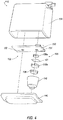
- FIG. 4 illustrates an exploded view of an example ground illumination system 110.
- the ground illumination system 110 may include a housing 118 configured to house the controller 130, as well as the image projector 120 and the light projector 122.
- the housing 118 may be closed by an optical lens 140.
- the optical lens 140 may reflect or bend the projections generated by the image projector 120 and the light projector 122.
- the image projector 120 may include a first light 131 coupled to the controller 130.
- the first light 131 may be a light emitting diode (LED) or plurality of LEDs configured to emit light.
- the image projector 120 may also include various filters 136 configured to aid in generating the logo.
- the optical filters may selectively transmit lights of different wavelengths.
- the image projector 120 may include a color filter configured to generate a color logo or image.
- the filters may be absorptive or dichroic. The filters may be selected during manufacturing depending on the type of image to be projected.
- the image projector 120 may include a first optical lens 156a and a film 141 having an outline of an image.
- the film 141 may allow certain light to pass through the film 141, while blocking other light, in order to generate the image.
- This film 141 may be interchangeable at the manufacturing stages in order to customize the image for each vehicle.
- the film 141 and filters 136 may be arranged and maintained in an optical assembly 142.
- the optical assembly 142 may then be locked into place within the housing 118 by the lens 140.
- the image projector 120 may also include a second optical lens 156b followed by a filter 136.
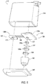
- Figure 5 illustrates an exploded view of another example ground illumination system 110.
- the controller 130 may be formed of a first controller 130a and a second controller 130b.
- the two controllers 130a, 130b are interconnected by wired connections 144, which may include a pair of cables, terminals or flexible circuits, configured to pass power from the first controller 130a to the second controller 130b.
- the first controller 130a may be configured to control and power the first light 131, as well as the other components of the image projector 120.
- the second controller 130b may be configured to power and control a second light 132 and the light projector 122.
- the light projector 122 may include the second light 132.
- the second light 132 may be a light, an LED or plurality of LEDs configured to emit light, similar to the first light 131.
- the second light 132 may be a white LED configured to emit substantially white light.
- the first light 131 may include any one of a color light, wherein a white LED may pass through various filters 136.
- Figure 6 illustrates an exploded view of another example ground illumination system 110.
- the image projector 120 may include a remote phosphor filter 150.
- Remote phosphor filters 150 may combine with the first light 131 to enhance the color projection of the image.
- the image projector 120 may also include an optical lens 156a, 156b arranged after the remote phosphor filter 150.
- the light projector 122 may also include a reflector 157 with a remote phosphor filter 152. This may allow the light projection to alter in color and brightness. The light may pass through the remote phosphor filter 152 to change the color.
- Figure 7 illustrates an exploded view of another example ground illumination system 110.
- the light projector 122 may include a remote phosphor filter 152 and an optical lens 156.
- the optical lens 156 may aid in bending the light to create the light projection 128.
- the phosphor filter 152 may be mounted on the lens 156. This may be the case for each of the image projector 120 and the light projector 122.
- Figure 8 illustrates an exploded view of another example ground illumination system 110.
- the image projector 120 may include a laser projector 158 and a diffracted lens 160.
- the laser projector 158 may project light and/or images for the image projection 126.
- the diffracted lens 160 may include the logo to be projected and may diffract the light provided by the laser projector 158 to display the image.
- the image projector 120 may also include a PICO projector module in lieu of the laser projector 158 of Figure 8 .
- the PICO projector may emit an image for the image projection 126.
- the system 110 may include the housing 118 capped at the bottom by the outer optical lens.
- a housing cover may be arranged at the top of the housing.
- the housing cover may include ribs disposed in a circular axis to radiate heat from the first light and second light.
- a gasket may be arranged between the housing 118 and the housing cover, and may maintain some of the components within the housing 118 at a fixed location.
- the first controller 130a and second controller 130b may be arranged within the housing 118.
- the second controller 130b may be aluminum to aid in dissipating heat from the white LED of the second light 132.
- the housing 118 may also house at least one of the optical lenses 156. In some examples, two, three, or more, optical lenses 156 may be included in the system 110.
- the film 141, hosting the image or logo, may also be included.
- the film 141 and optical lens 156 may include a pair of collimating lenses followed by the film 141, followed by a focusing lens (not shown).
- the housing 118 may be enclosed by the housing cover and the outer optical lens 140. Further, the housing 118, outer optical lens 140, and housing cover may be hermetically sealed in order to protect the elements therein.
- the housing cover and lens may be over-molded to the housing 118 in order to hermetically seal the housing 118 and protect the elements therein. This may allow multiple materials to be sealed and assembled and decrease tooling and assembly time.
- Computing devices described herein generally include computer-executable instructions, where the instructions may be executable by one or more computing or hardware devices, such as those listed above.
- Computer-executable instructions may be compiled or interpreted from computer programs created using a variety of programming languages and/or technologies, including, without limitation, and either alone or in combination, JavaTM, C, C++, Visual Basic, Java Script, Perl, etc.
- a processor e.g., a microprocessor
- receives instructions e.g. , from a memory, a computer-readable medium, etc.
- executes these instructions thereby performing one or more processes, including one or more of the processes described herein.
- Such instructions and other data may be stored and transmitted using a variety of computer-readable media.
Landscapes
- Engineering & Computer Science (AREA)
- Mechanical Engineering (AREA)
- Physics & Mathematics (AREA)
- General Physics & Mathematics (AREA)
- Lighting Device Outwards From Vehicle And Optical Signal (AREA)
- Non-Portable Lighting Devices Or Systems Thereof (AREA)
Abstract
A vehicle ground illumination system may include a housing configured to maintain an image projector and a light projector and a controller in communication with the image projector and the light projector. The controller may be configured to instruct the image projector to project an image in an illumination area, and instruct the light projector to project a white light in the illumination area, wherein the white light is projected to at least partially surround the image projector.
Description
- The present invention relates to a vehicle ground illumination system and vehicle winglet. Disclosed herein are puddle lamps with static and dynamic image projections.
- Motor vehicles include various exterior and interior lamps for increasing visibility during non-daylight hours. These lamps may be automatic, and may include head-lamps, interior running lights, etc.
- A vehicle ground illumination system may include a housing configured to maintain an image projector and a light projector and a controller in communication with the image projector and the light projector. The controller may be configured to instruct the image projector to project an image in an illumination area, and instruct the light projector to project a white light in the illumination area, wherein the white light is projected to at least partially surround the image projector.
- A vehicle mirror having a vehicle ground illumination system, e.g. as disclosed above, may include a housing configured to maintain an image projector and a light projector, the image projector having a first light and being arranged within the housing, and configured to project an image in an illumination area, and the light projector having a second light and being arranged within the housing and configured to project a light in the illumination area, wherein the light is projected to at least partially surround the image projector.
- The embodiments of the present disclosure are pointed out with particularity in the appended claims. However, other features of the various embodiments will become more apparent and will be best understood by referring to the following detailed description in conjunction with the accompanying drawings in which:
-
Figure 1 illustrates an example lighted system for a vehicle; -
Figure 2 illustrates a cut-away view of an example ground illumination system; -
Figure 3 illustrates an example perspective view of the illumination area of the ground illumination system ofFigure 2 ; -
Figure 4 illustrates an exploded view of the example ground illumination system; -
Figure 5 illustrates an exploded view of another example ground illumination system; -
Figure 6 illustrates an exploded view of another example ground illumination system; -
Figure 7 illustrates an exploded view of another example ground illumination system; and -
Figure 8 illustrates an exploded view of another example ground illumination system. - As required, detailed embodiments of the present invention are disclosed herein; however, it is to be understood that the disclosed embodiments are merely exemplary of the invention that may be embodied in various and alternative forms. The figures are not necessarily to scale; some features may be exaggerated or minimized to show details of particular components. Therefore, specific structural and functional details disclosed herein are not to be interpreted as limiting, but merely as a representative basis for teaching one skilled in the art to variously employ the present invention.
- Disclosed herein is a ground illumination system for a vehicle that includes a light source configured to emit light. The system includes a reconfigurable display element to project an image in combination with a light projector or laser or PICO projector. The light projection and the image projection may be combined in a single unit wherein an icon or animated image may be projected within an area illuminated by the light source. The logo or image may be customizable during manufacturing.
-
Figure 1 illustrates an example lightedvehicle system 100 for avehicle 102. Thevehicle 102 is illustrated as a truck, but may be any motor passenger vehicle including but not limited to a truck, sport utility vehicle, cross-over, hatchback, station wagon, motorcycle, all-terrain vehicle (ATV), recreational vehicle (RV), boat, plane or other mobile machine for transporting people or goods, etc. - The
vehicle 102 may include at least onewinglet 104, such as a vehicle mirror (as shown inFigure 1 ) or camera or radar. Thewinglet 104 may also be a roof rack, door handle, or other protrusion of the vehicle or vehicle component. Thewinglet 104 may house aground illumination system 110 configured to create anilluminated area 114 at or near thevehicle 102. The illuminated portion, referred to herein as theilluminated area 114, may provide a lighted area in front of the vehicle, as well as display an image, such as a logo within theilluminated area 114. - While the
light mechanism 110 is described throughout as being arranged on thewinglet 104, thelight mechanism 110 may also be mounted on other exterior areas of thevehicle 102. For example, thelight mechanism 110 may be arranged on a door handle. Thelight mechanism 110 may be arranged on running boards, mud flaps, roof racks, bumpers, etc. Thevehicle 102 may include more than onelight mechanism 110. In one example, alight mechanism 110 may be arranged on each side view mirror. Alight mechanism 110 may also be arranged on each door handle. -
Figure 2 illustrates a cut-away view of the exampleground illumination system 110 housed by thewinglet 104. Theground illumination system 110 may include ahousing 118 configured to maintain, house, or support animage projector 120 and alight projector 122. Theimage projector 120 may be a light mechanism configured to emit animage projection 126 onto theillumination area 114. Theimage projection 126 may include a logo or image relating to the vehicle, such as the vehicle's trademark, etc. Theimage projector 120 may be configured to emit both black and white, as well as colored images, into theillumination area 114. - The
light projector 122 may be configured to emit light into theillumination area 114, referred to herein as thelight projection 128. This may be intended to light up an area in front of the vehicle as a user approaches the vehicle. The light may include a white light or color light. - The
image projector 120 and thelight projector 122 may be coupled to acontroller 130. Thecontroller 130 may be coupled to a memory (not shown) and may be configured to control the illumination of theimage projector 120 and thelight projector 122. Thecontroller 130 may include a printed circuit board (PCB) configured to electronically couple theimage projector 120 and thelight projector 122. Thecontroller 130 or PCB may include a connector or dual wires. -
Figure 3 illustrates an example perspective view of theillumination area 114, including theimage projection 126 and thelight projection 128. As illustrated, theimage projection 126 may be at least partially maintained within thelight projection 128. Theimage projection 126 andlight projection 128 may be concurrently projected, or each projected individually. -
Figure 4 illustrates an exploded view of an exampleground illumination system 110. Theground illumination system 110 may include ahousing 118 configured to house thecontroller 130, as well as theimage projector 120 and thelight projector 122. Thehousing 118 may be closed by anoptical lens 140. Theoptical lens 140 may reflect or bend the projections generated by theimage projector 120 and thelight projector 122. - The
image projector 120 may include afirst light 131 coupled to thecontroller 130. Thefirst light 131 may be a light emitting diode (LED) or plurality of LEDs configured to emit light. Theimage projector 120 may also includevarious filters 136 configured to aid in generating the logo. The optical filters may selectively transmit lights of different wavelengths. For example, theimage projector 120 may include a color filter configured to generate a color logo or image. The filters may be absorptive or dichroic. The filters may be selected during manufacturing depending on the type of image to be projected. - The
image projector 120 may include a firstoptical lens 156a and afilm 141 having an outline of an image. Thefilm 141 may allow certain light to pass through thefilm 141, while blocking other light, in order to generate the image. Thisfilm 141 may be interchangeable at the manufacturing stages in order to customize the image for each vehicle. Thefilm 141 andfilters 136 may be arranged and maintained in anoptical assembly 142. Theoptical assembly 142 may then be locked into place within thehousing 118 by thelens 140. Theimage projector 120 may also include a secondoptical lens 156b followed by afilter 136. -
Figure 5 illustrates an exploded view of another exampleground illumination system 110. In thissystem 110, thecontroller 130 may be formed of afirst controller 130a and asecond controller 130b. The twocontrollers wired connections 144, which may include a pair of cables, terminals or flexible circuits, configured to pass power from thefirst controller 130a to thesecond controller 130b. Thefirst controller 130a may be configured to control and power thefirst light 131, as well as the other components of theimage projector 120. Thesecond controller 130b may be configured to power and control asecond light 132 and thelight projector 122. - The
light projector 122 may include thesecond light 132. Thesecond light 132 may be a light, an LED or plurality of LEDs configured to emit light, similar to thefirst light 131. In one example, thesecond light 132 may be a white LED configured to emit substantially white light. Thefirst light 131 may include any one of a color light, wherein a white LED may pass throughvarious filters 136. -
Figure 6 illustrates an exploded view of another exampleground illumination system 110. In this example, theimage projector 120 may include aremote phosphor filter 150. Remote phosphor filters 150 may combine with thefirst light 131 to enhance the color projection of the image. Theimage projector 120 may also include anoptical lens remote phosphor filter 150. - The
light projector 122 may also include areflector 157 with aremote phosphor filter 152. This may allow the light projection to alter in color and brightness. The light may pass through theremote phosphor filter 152 to change the color. -
Figure 7 illustrates an exploded view of another exampleground illumination system 110. In this example, thelight projector 122 may include aremote phosphor filter 152 and anoptical lens 156. Theoptical lens 156 may aid in bending the light to create thelight projection 128. In the examples where the phosphor filter is included, thephosphor filter 152 may be mounted on thelens 156. This may be the case for each of theimage projector 120 and thelight projector 122. -
Figure 8 illustrates an exploded view of another exampleground illumination system 110. In this example, theimage projector 120 may include alaser projector 158 and a diffractedlens 160. Thelaser projector 158 may project light and/or images for theimage projection 126. The diffractedlens 160 may include the logo to be projected and may diffract the light provided by thelaser projector 158 to display the image. - Although not specifically shown, the
image projector 120 may also include a PICO projector module in lieu of thelaser projector 158 ofFigure 8 . The PICO projector may emit an image for theimage projection 126. - The
system 110 may include thehousing 118 capped at the bottom by the outer optical lens. A housing cover may be arranged at the top of the housing. The housing cover may include ribs disposed in a circular axis to radiate heat from the first light and second light. A gasket may be arranged between thehousing 118 and the housing cover, and may maintain some of the components within thehousing 118 at a fixed location. Thefirst controller 130a andsecond controller 130b, may be arranged within thehousing 118. Thesecond controller 130b may be aluminum to aid in dissipating heat from the white LED of thesecond light 132. Thehousing 118 may also house at least one of theoptical lenses 156. In some examples, two, three, or more,optical lenses 156 may be included in thesystem 110. Thefilm 141, hosting the image or logo, may also be included. - In one example, the
film 141 andoptical lens 156 may include a pair of collimating lenses followed by thefilm 141, followed by a focusing lens (not shown). Thehousing 118 may be enclosed by the housing cover and the outeroptical lens 140. Further, thehousing 118, outeroptical lens 140, and housing cover may be hermetically sealed in order to protect the elements therein. The housing cover and lens may be over-molded to thehousing 118 in order to hermetically seal thehousing 118 and protect the elements therein. This may allow multiple materials to be sealed and assembled and decrease tooling and assembly time. - Computing devices described herein generally include computer-executable instructions, where the instructions may be executable by one or more computing or hardware devices, such as those listed above. Computer-executable instructions may be compiled or interpreted from computer programs created using a variety of programming languages and/or technologies, including, without limitation, and either alone or in combination, Java™, C, C++, Visual Basic, Java Script, Perl, etc. In general, a processor (e.g., a microprocessor) receives instructions (e.g., from a memory, a computer-readable medium, etc.) and executes these instructions, thereby performing one or more processes, including one or more of the processes described herein. Such instructions and other data may be stored and transmitted using a variety of computer-readable media.
- While exemplary embodiments are described above, it is not intended that these embodiments describe all possible forms of the invention. Rather, the words used in the specification are words of description rather than limitation, and it is understood that various changes may be made without departing from the spirit and scope of the invention. Additionally, the features of various implementing embodiments may be combined to form further embodiments of the invention.
- Further Embodiments:
- 1. A vehicle ground illumination system, comprising:
- a housing configured to maintain an image projector and a light projector;
- a controller in communication with the image projector and the light projector, and configured to:
- instruct the image projector to project an image in an illumination area; and
- instruct the light projector to project a white light in the illumination area, wherein the white light is projected to at least partially surround the image projector.
- 2. The system of
embodiment 1, wherein the controller includes a first controller configured to control the image projector and a second controller configured to control the light projector. - 3. The system of embodiment 2, wherein the image projector includes a first light and the light projector includes a second light, the first controller being coupled to the first light of the image projector and the second controller being coupled to the second light of the light projector.
- 4. The system of embodiment 2, wherein the first and second controllers are coupled to each other via a wired connection.
- 5. The system of
embodiment 1, wherein the image projector includes a laser projector. - 6. The system of
embodiment 1, wherein the image projector includes a PICO projector. - 7. The system of
embodiment 1, wherein the image projector includes a color filter. - 8. The system of
embodiment 1, wherein the image projector includes a remote phosphor filter and a diffractor lens. - 9. The system of
embodiment 1, wherein the image projector includes a film hosting the image. - 10. The system of
embodiment 1, wherein the light projector includes a light emitting diode. - 11. The system of
embodiment 1, wherein the light projector includes an optical lens. - 12. The system of
embodiment 1, wherein the light projector includes a remote phosphor filter. - 13. A vehicle winglet having a vehicle ground illumination system, comprising:
- a housing configured to maintain an image projector and a light projector;
- the image projector having a first light and being arranged within the housing, and configured to project an image in an illumination area; and
- the light projector having a second light and being arranged within the housing and configured to project a light in the illumination area, wherein the light is projected to at least partially surround the image projector.
- 14. The winglet of embodiment 13, further comprising a controller in communication with each of the image projector and light projector, wherein the controller is configured to provide power to the image projector and light projector.
- 15. The winglet of embodiment 14, wherein the controller includes a first controller configured to control the image projector and a second controller configured to control the light projector.
- 16. The winglet of embodiment 15, wherein the first and second controllers are coupled to each other via a wired connection.
- 17. The winglet of embodiment 13, wherein the image projector includes at least one of a laser projector, a PICO projector, a color filter, a remote phosphor filter and a diffractor lens, and a film hosting the image.
- 18. The winglet of embodiment 13, wherein the light projector includes a white light emitting diode.
- 19. The winglet of embodiment 13, wherein the light projector includes an optical lens and a remote phosphor filter.
| lighted | 100 |
| | 102 |
| | 104 |
| | 110 |
| | 114 |
| | 118 |
| | 120 |
| | 122 |
| | 126 |
| | 128 |
| | 130 |
| | 130a |
| | 130b |
| | 131 |
| second light | 132 |
| | 136 |
| | 140 |
| | 141 |
| | 142 |
| | 144 |
| | 150 |
| | 152 |
| first | 156a |
| second | 156b |
| reflector | |
| 157 | |
| | 158 |
| diffracted | 160 |
Claims (15)
- A vehicle ground illumination system (100), comprising:a housing (118) configured to maintain an image projector (120) and a light projector (122);a controller (130, 130a, 130b) in communication with the image projector and the light projector (122), and configured to:instruct the image projector (120) to project an image in an illumination area (114); andinstruct the light projector (122) to project a white light in the illumination area (114), wherein the white light is projected to at least partially surround the image projector (120).
- The system according to claim 1, wherein the controller (130, 130a, 130b) includes a first controller (130a) configured to control the image projector (120) and a second controller (130b) configured to control the light projector (122).
- The system according to any of the preceding claims wherein the image projector (120) includes a first light (131) and the light projector (122) includes a second light (132), the first controller (130a) being coupled to the first light (131) of the image projector (122) and the second controller (130b) being coupled to the second light (132) of the light projector (122).
- The system according to any of the preceding claims, wherein the first and second controllers (130a, 130b) are coupled to each other via a wired connection (144).
- The system according to any of the preceding claims, wherein the image projector (120) includes at least one of: a laser projector (158), a PICO projector, and a color filter.
- The system according to any of the preceding claims, wherein the image projector (120) includes a remote phosphor filter (150) and a diffractor lens (160).
- The system according to any of the preceding claims, wherein the image projector (120) includes a film (141) hosting the image.
- The system according to any of the preceding claims, wherein the light projector (122) includes at least one of: a light emitting diode, an optical lens (140), and a remote phosphor filter (152).
- A vehicle winglet (104) having a vehicle ground illumination system (100), in particular a vehicle ground illumination system (100) according to any of the claims 1 to 8, the vehicle ground illumination system (100) comprising:a housing (118) configured to maintain an image projector (120) and a light projector (122);the image projector (120) having a first light (131) and being arranged within the housing (118), and configured to project an image in an illumination area (114); andthe light projector (122) having a second light (132) and being arranged within the housing (118) and configured to project a light in the illumination area (114), wherein the light is projected to at least partially surround the image projector (120).
- The winglet according to claim 9, further comprising a controller (130, 130a, 130b) in communication with each of the image projector (120) and light projector (122), wherein the controller (130, 130a, 130b) is configured to provide power to the image projector (120) and light projector (122).
- The winglet according to any of the preceding winglet based claims, wherein the controller (130, 130a, 130b) includes a first controller (130a) configured to control the image projector (120) and a second controller (130b) configured to control the light projector (122).
- The winglet according to any of the preceding winglet based claims, wherein the first and second controllers (130a, 130b) are coupled to each other via a wired connection (144).
- The winglet according to any of the preceding winglet based claims, wherein the image projector (120) includes at least one of a laser projector (158), a PICO projector, a color filter, a remote phosphor filter (150) and a diffractor lens (160), and a film (141) hosting the image.
- The winglet according to any of the preceding winglet based claims, wherein the light projector (122) includes a white light emitting diode.
- The winglet according to any of the preceding winglet based claims, wherein the light projector (122) includes an optical lens (140) and a remote phosphor filter (152).
Applications Claiming Priority (1)
| Application Number | Priority Date | Filing Date | Title |
|---|---|---|---|
| US16/224,041 US20200189451A1 (en) | 2018-12-18 | 2018-12-18 | Puddle lamp with static and dynamic image projection |
Publications (1)
| Publication Number | Publication Date |
|---|---|
| EP3674795A1 true EP3674795A1 (en) | 2020-07-01 |
Family
ID=68965619
Family Applications (1)
| Application Number | Title | Priority Date | Filing Date |
|---|---|---|---|
| EP19217552.9A Withdrawn EP3674795A1 (en) | 2018-12-18 | 2019-12-18 | Vehicle ground illumination system and vehicle winglet |
Country Status (3)
| Country | Link |
|---|---|
| US (1) | US20200189451A1 (en) |
| EP (1) | EP3674795A1 (en) |
| CN (1) | CN111332189A (en) |
Families Citing this family (4)
| Publication number | Priority date | Publication date | Assignee | Title |
|---|---|---|---|---|
| US10946815B1 (en) * | 2020-03-02 | 2021-03-16 | Ford Global Technologies, Llc | Vehicle badge assembly |
| KR102908594B1 (en) * | 2020-09-07 | 2026-01-08 | 현대자동차주식회사 | Puddle lamp device for an image display |
| CN113464897A (en) * | 2021-07-21 | 2021-10-01 | 广东烨嘉光电科技股份有限公司 | Distributed projection lamp group system with enhanced brightness |
| EP4253150B1 (en) * | 2022-03-29 | 2024-05-01 | Motherson Innovations Company Limited | Hybrid semi-dynamic animated logo lamp, vehicle component and vehicle |
Citations (3)
| Publication number | Priority date | Publication date | Assignee | Title |
|---|---|---|---|---|
| US20110273671A1 (en) * | 2010-05-07 | 2011-11-10 | Idesign Max Co., Ltd. | Projector for Casting Light on the Ground beside a Vehicle |
| US20180118099A1 (en) * | 2015-04-10 | 2018-05-03 | Maxell, Ltd. | Image projection apparatus |
| DE102018105563A1 (en) * | 2017-03-15 | 2018-09-20 | Panasonic Intellectual Property Management Co., Ltd. | Lighting device, moving body and control program and data carrier |
Family Cites Families (4)
| Publication number | Priority date | Publication date | Assignee | Title |
|---|---|---|---|---|
| US7589622B2 (en) * | 2006-08-14 | 2009-09-15 | Farley's Custom Auto Services, Llc | Emergency vehicle warning lights |
| US8838308B2 (en) * | 2010-05-27 | 2014-09-16 | Boxx Corp. | Two wheeled vehicle with modular features |
| ES2561133B1 (en) * | 2014-07-24 | 2016-12-01 | Alejandro Rodriguez Barros | MULTIFUNCTION OUTDOOR REAR VIEW MIRROR WITH LASER ISSUED DEVICE |
| WO2018096523A1 (en) * | 2016-11-28 | 2018-05-31 | Magna Mirrors Of America, Inc. | Exterior illumination and icon projection module for vehicle |
-
2018
- 2018-12-18 US US16/224,041 patent/US20200189451A1/en not_active Abandoned
-
2019
- 2019-12-18 EP EP19217552.9A patent/EP3674795A1/en not_active Withdrawn
- 2019-12-18 CN CN201911307079.1A patent/CN111332189A/en active Pending
Patent Citations (3)
| Publication number | Priority date | Publication date | Assignee | Title |
|---|---|---|---|---|
| US20110273671A1 (en) * | 2010-05-07 | 2011-11-10 | Idesign Max Co., Ltd. | Projector for Casting Light on the Ground beside a Vehicle |
| US20180118099A1 (en) * | 2015-04-10 | 2018-05-03 | Maxell, Ltd. | Image projection apparatus |
| DE102018105563A1 (en) * | 2017-03-15 | 2018-09-20 | Panasonic Intellectual Property Management Co., Ltd. | Lighting device, moving body and control program and data carrier |
Also Published As
| Publication number | Publication date |
|---|---|
| CN111332189A (en) | 2020-06-26 |
| US20200189451A1 (en) | 2020-06-18 |
Similar Documents
| Publication | Publication Date | Title |
|---|---|---|
| EP3674795A1 (en) | Vehicle ground illumination system and vehicle winglet | |
| KR101277299B1 (en) | Integrated lamp device for vehicle side mirror | |
| CN1882236B (en) | Displays with indirect lighting structures | |
| US10185210B2 (en) | Luminous light emitting device, light source unit and image projection system | |
| JP6831692B2 (en) | Vehicle lamp | |
| KR20170095668A (en) | Lamp and Vehicle having the same | |
| US10738960B1 (en) | Interchangeable logo courtesy lamp | |
| US11009202B2 (en) | Universal dual infrared and white light bulb | |
| US8608358B2 (en) | Lighting device of a motor vehicle | |
| JP2015099638A (en) | Vehicle signal lights | |
| US20240377041A1 (en) | Led module for vehicle headlight and vehicle headlight with such led module | |
| JP2006011168A (en) | Head-up display device for vehicle | |
| JP2005320004A (en) | Indicator and illuminator using semiconductor light emitting emitter package | |
| KR20150065169A (en) | Camera for watching back of Vehicle | |
| CN101111710A (en) | Car headlights | |
| CN114258471A (en) | Vehicle lamp | |
| US12196387B2 (en) | Lighting device for rear-view device of vehicle | |
| CN112092719B (en) | Lighting equipment for autonomous vehicles | |
| EP4579336A1 (en) | Light projection device | |
| JP2005035455A (en) | Infrared projector for vehicles | |
| JP7827249B2 (en) | Bendable lighting device | |
| US20050024197A1 (en) | Auxiliary directional light device for an automobile | |
| US20230272894A1 (en) | Optically embedded flexible filament | |
| US12135116B1 (en) | Multi-functional light module for an exterior mirror | |
| US12228263B1 (en) | Light module for an exterior mirror |
Legal Events
| Date | Code | Title | Description |
|---|---|---|---|
| PUAI | Public reference made under article 153(3) epc to a published international application that has entered the european phase |
Free format text: ORIGINAL CODE: 0009012 |
|
| STAA | Information on the status of an ep patent application or granted ep patent |
Free format text: STATUS: THE APPLICATION HAS BEEN PUBLISHED |
|
| AK | Designated contracting states |
Kind code of ref document: A1 Designated state(s): AL AT BE BG CH CY CZ DE DK EE ES FI FR GB GR HR HU IE IS IT LI LT LU LV MC MK MT NL NO PL PT RO RS SE SI SK SM TR |
|
| AX | Request for extension of the european patent |
Extension state: BA ME |
|
| STAA | Information on the status of an ep patent application or granted ep patent |
Free format text: STATUS: THE APPLICATION IS DEEMED TO BE WITHDRAWN |
|
| 18D | Application deemed to be withdrawn |
Effective date: 20210112 |