EP3674749A1 - Distance measurement device and optical scanning device - Google Patents
Distance measurement device and optical scanning device Download PDFInfo
- Publication number
- EP3674749A1 EP3674749A1 EP18860853.3A EP18860853A EP3674749A1 EP 3674749 A1 EP3674749 A1 EP 3674749A1 EP 18860853 A EP18860853 A EP 18860853A EP 3674749 A1 EP3674749 A1 EP 3674749A1
- Authority
- EP
- European Patent Office
- Prior art keywords
- light
- ranging
- scanning
- unit
- pulsed light
- Prior art date
- Legal status (The legal status is an assumption and is not a legal conclusion. Google has not performed a legal analysis and makes no representation as to the accuracy of the status listed.)
- Pending
Links
Images


Classifications
-
- G—PHYSICS
- G01—MEASURING; TESTING
- G01S—RADIO DIRECTION-FINDING; RADIO NAVIGATION; DETERMINING DISTANCE OR VELOCITY BY USE OF RADIO WAVES; LOCATING OR PRESENCE-DETECTING BY USE OF THE REFLECTION OR RERADIATION OF RADIO WAVES; ANALOGOUS ARRANGEMENTS USING OTHER WAVES
- G01S7/00—Details of systems according to groups G01S13/00, G01S15/00, G01S17/00
- G01S7/48—Details of systems according to groups G01S13/00, G01S15/00, G01S17/00 of systems according to group G01S17/00
- G01S7/481—Constructional features, e.g. arrangements of optical elements
- G01S7/4817—Constructional features, e.g. arrangements of optical elements relating to scanning
-
- G—PHYSICS
- G01—MEASURING; TESTING
- G01S—RADIO DIRECTION-FINDING; RADIO NAVIGATION; DETERMINING DISTANCE OR VELOCITY BY USE OF RADIO WAVES; LOCATING OR PRESENCE-DETECTING BY USE OF THE REFLECTION OR RERADIATION OF RADIO WAVES; ANALOGOUS ARRANGEMENTS USING OTHER WAVES
- G01S7/00—Details of systems according to groups G01S13/00, G01S15/00, G01S17/00
- G01S7/48—Details of systems according to groups G01S13/00, G01S15/00, G01S17/00 of systems according to group G01S17/00
- G01S7/483—Details of pulse systems
- G01S7/484—Transmitters
-
- G—PHYSICS
- G01—MEASURING; TESTING
- G01S—RADIO DIRECTION-FINDING; RADIO NAVIGATION; DETERMINING DISTANCE OR VELOCITY BY USE OF RADIO WAVES; LOCATING OR PRESENCE-DETECTING BY USE OF THE REFLECTION OR RERADIATION OF RADIO WAVES; ANALOGOUS ARRANGEMENTS USING OTHER WAVES
- G01S17/00—Systems using the reflection or reradiation of electromagnetic waves other than radio waves, e.g. lidar systems
- G01S17/02—Systems using the reflection of electromagnetic waves other than radio waves
- G01S17/06—Systems determining position data of a target
- G01S17/08—Systems determining position data of a target for measuring distance only
- G01S17/10—Systems determining position data of a target for measuring distance only using transmission of interrupted, pulse-modulated waves
-
- G—PHYSICS
- G01—MEASURING; TESTING
- G01S—RADIO DIRECTION-FINDING; RADIO NAVIGATION; DETERMINING DISTANCE OR VELOCITY BY USE OF RADIO WAVES; LOCATING OR PRESENCE-DETECTING BY USE OF THE REFLECTION OR RERADIATION OF RADIO WAVES; ANALOGOUS ARRANGEMENTS USING OTHER WAVES
- G01S17/00—Systems using the reflection or reradiation of electromagnetic waves other than radio waves, e.g. lidar systems
- G01S17/02—Systems using the reflection of electromagnetic waves other than radio waves
- G01S17/06—Systems determining position data of a target
- G01S17/42—Simultaneous measurement of distance and other co-ordinates
-
- G—PHYSICS
- G01—MEASURING; TESTING
- G01S—RADIO DIRECTION-FINDING; RADIO NAVIGATION; DETERMINING DISTANCE OR VELOCITY BY USE OF RADIO WAVES; LOCATING OR PRESENCE-DETECTING BY USE OF THE REFLECTION OR RERADIATION OF RADIO WAVES; ANALOGOUS ARRANGEMENTS USING OTHER WAVES
- G01S17/00—Systems using the reflection or reradiation of electromagnetic waves other than radio waves, e.g. lidar systems
- G01S17/88—Lidar systems specially adapted for specific applications
- G01S17/89—Lidar systems specially adapted for specific applications for mapping or imaging
-
- G—PHYSICS
- G02—OPTICS
- G02B—OPTICAL ELEMENTS, SYSTEMS OR APPARATUS
- G02B26/00—Optical devices or arrangements for the control of light using movable or deformable optical elements
- G02B26/08—Optical devices or arrangements for the control of light using movable or deformable optical elements for controlling the direction of light
- G02B26/0816—Optical devices or arrangements for the control of light using movable or deformable optical elements for controlling the direction of light by means of one or more reflecting elements
- G02B26/0833—Optical devices or arrangements for the control of light using movable or deformable optical elements for controlling the direction of light by means of one or more reflecting elements the reflecting element being a micromechanical device, e.g. a MEMS mirror, DMD
-
- G—PHYSICS
- G02—OPTICS
- G02B—OPTICAL ELEMENTS, SYSTEMS OR APPARATUS
- G02B26/00—Optical devices or arrangements for the control of light using movable or deformable optical elements
- G02B26/08—Optical devices or arrangements for the control of light using movable or deformable optical elements for controlling the direction of light
- G02B26/10—Scanning systems
- G02B26/101—Scanning systems with both horizontal and vertical deflecting means, e.g. raster or XY scanners
Definitions
- An invention described in Claim 7 includes a light source unit that emits a light; an optical scanning unit that scans a predetermined region by the light while changing an irradiation direction of the light; a light receiving unit that receives a reflected light from an object where the light is irradiated; and a control unit that controls an emission of the light.
- the optical scanning unit is configured to emit the light multiple times in an identical direction during one scanning cycle, and the control unit controls a count of irradiation of the light in the identical direction during the one scanning cycle based on a predetermined condition on the reflected light.
Landscapes
- Physics & Mathematics (AREA)
- Engineering & Computer Science (AREA)
- General Physics & Mathematics (AREA)
- Computer Networks & Wireless Communication (AREA)
- Radar, Positioning & Navigation (AREA)
- Remote Sensing (AREA)
- Electromagnetism (AREA)
- Optics & Photonics (AREA)
- Optical Radar Systems And Details Thereof (AREA)
- Mechanical Optical Scanning Systems (AREA)
Abstract
Description
- The present invention relates to an optical scanning device performing optical scanning and a ranging device performing optical ranging.
- For example, a ranging device is configured to measure a distance to an object by irradiating the object inside a target region with light to detect the light reflected by the object. For example, there is known a ranging device that performs two-dimensional or three-dimensional ranging by performing an optical scanning of the target region using an optical scanner.
- An optical scanning type ranging device includes, for example, a Micro Electro Mechanical Systems (MEMS) mirror as the optical scanning device. For example, the MEMS mirror is provided with a light reflecting surface, which two-dimensionally swings (oscillates). Irradiating the light reflecting surface with light enables the scanning of the target region with the light reflected by the light reflecting surface. For example, Patent document 1 discloses an optical ranging device having an optical scanning unit that can perform Lissajous scanning of light incident on a light reflecting surface inside a target region by swinging a movable portion with the light reflecting surface.
- Patent Document 1: Japanese Patent Application Laid-Open No.
2011-053137 - An optical scanning type ranging device sets each of a plurality of points inside a scanning trajectory as a ranging point to perform a ranging operation for each of the ranging points. Here, for example, in the case of performing scanning by the trajectory along a Lissajous curve, an optical scanning is performed such that the scanning trajectory intersects. In this case, it is assumed that, within one scanning cycle (a ranging cycle), multiple times of the ranging operations are performed to an identical ranging point. For example, when an accurate ranging result is acquired at the first ranging on the identical ranging point, a second ranging operation sometimes become unnecessary.
- Therefore, in the case of such a scanning method where the scanning trajectory intersects, it is preferable that the ranging operation performed to the intersection point is performed under a different condition from the ranging operation performed on other ranging points that do not intersect. For example, corresponding to, for example, a ranging processing rate and ranging accuracy required to the device, it is preferable that execution and non-execution of each of the multiple times of the ranging operations, which are allowed to perform within one ranging cycle, at the intersection point are switchable.
- Not limited to a ranging purpose, in the optical scanning device having a scanning mode that scans an overlapped point multiple times within a predetermined scanning cycle, it is preferable that the scanning at a point where the scanning position overlaps is performed under different conditions from the scanning at the other scanning position.
- The present invention has been made in consideration of the above-described point. It is one of the problems for the present invention to provide a ranging device that ensures adjusting conditions of a ranging operation at a ranging point where the scanning trajectory intersects. Additionally, it is one of the problems for the present invention to provide an optical scanning device that ensures adjusting the conditions of the scanning operation at the point where the scanning trajectory intersects.
- An invention described in Claim 1 includes a light source unit that emits a pulsed light; an optical scanning unit that scans a predetermined region with the pulsed light and has an intersection point where a path of the pulsed light intersects when viewing a virtual surface inside the predetermined region; a ranging unit that receives a reflected light from an object irradiated with the pulsed light to measure a distance to the object; and a control unit that controls an emission of the pulsed light to the intersection point based on a predetermined condition on the reflected light.
- An invention described in Claim 7 includes a light source unit that emits a light; an optical scanning unit that scans a predetermined region by the light while changing an irradiation direction of the light; a light receiving unit that receives a reflected light from an object where the light is irradiated; and a control unit that controls an emission of the light. The optical scanning unit is configured to emit the light multiple times in an identical direction during one scanning cycle, and the control unit controls a count of irradiation of the light in the identical direction during the one scanning cycle based on a predetermined condition on the reflected light.
-
-
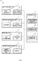
FIG. 1 is a block diagram of a ranging device according to Embodiment 1. -
FIG. 2A is a top view of a scanner in the ranging device according to Embodiment 1. -
FIG. 2B is a cross-sectional view of the scanner in the ranging device according to Embodiment 1. -
FIG. 3A is a schematic operation explanation drawing of the ranging device according to Embodiment 1. -
FIG. 3B is the schematic operation explanation drawing of the ranging device according to Embodiment 1. -
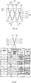
FIG. 4 is a drawing illustrating waveform of a driving signal applied to the scanner of the ranging device according to Embodiment 1 and a scanning path of a pulsed light by the scanner. -
FIG. 5A is a drawing illustrating a ranging point of the ranging device according to Embodiment 1. -
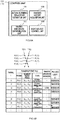
FIG. 5B is a drawing illustrating an emission configuration of the pulsed light at the ranging point in the ranging device according to Embodiment 1. -
FIG. 6A is a block diagram of a control unit in the ranging device according to Embodiment 2. -
FIG. 6B is a drawing illustrating an emission configuration of the pulsed light at the ranging point in the ranging device according to Embodiment 2. - The following describes Embodiments of the present invention in detail.
-
FIG. 1 is a block diagram of a rangingdevice 10 according to Embodiment 1. The rangingdevice 10 is an optical ranging device that optically measures a distance to an object. UsingFIG. 1 , an overall configuration of the rangingdevice 10 will be described. - First, in this Embodiment, the ranging
device 10 includes alight source unit 11 that includes alight source 11A and a lightsource driving circuit 11B for driving thelight source 11A. Thelight source 11A generates and emits a pulsed laser light (hereinafter referred to as a pulsed light). The lightsource driving circuit 11B generates a driving signal for thelight source 11A to emit the pulsed light to apply to thelight source 11A. - The ranging
device 10 has anoptical scanning unit 12 that scans a region (hereinafter referred to as a scanning target region) including a region as a ranging target (hereinafter referred to as an effective scanning region), using the pulsed light emitted from thelight source 11A of thelight source unit 11. In the Embodiment, theoptical scanning unit 12 includes a scanner (an optical scanning means) 12A that execute the optical scanning of the scanning target region using the pulsed light and ascanner driving circuit 12B driving thescanner 12A. Thescanner driving circuit 12B generates a driving signal driving thescanner 12A to apply to thescanner 12A. - The ranging
device 10 has a rangingunit 13 that receives the light obtained by an operation of thescanner 12A of theoptical scanning unit 12 to measure a distance to an object existing inside the effective scanning region. In the Embodiment, the rangingunit 13 has alight receiving unit 13A that receives and detects the light where the pulsed light is reflected by the object (hereinafter referred to as reflected light) and ameasuring unit 13B that measures the distance between the rangingdevice 10 and the object based on the reflected light received by thelight receiving unit 13A. - In the Embodiment, the ranging
unit 13 generates ranging data that indicates a ranging result (distance information) to the object to which each of light pulses of the pulsed light is irradiated. For example, in the Embodiment, the rangingunit 13 generates a piece of the ranging data including a plurality of pieces of the distance information for each scanning cycle by theoptical scanning unit 12. In the case when the scanning to the scanning target region is repeated, the scanning cycle means a period until a time point where a scanning state at an optional time point subsequently returns to the scanning state again. - The ranging
device 10 has aninformation processing unit 14 that performs various kinds of processes to the information indicating the ranging result by the rangingunit 13. In the Embodiment, theinformation processing unit 14 has animage generation unit 14A that generates image data imaging the ranging data generated by the rangingunit 13 as a two-dimensional or a three-dimensional map, and adisplay 14B displaying the image data. - In the Embodiment, the
image generation unit 14A converts each of the plurality of pieces of the ranging data, which is generated by the rangingunit 13 at each scanning cycle of theoptical scanning unit 12, to the image data. Thedisplay 14B displays the plurality of pieces of the image data as a moving image along a time series. - The ranging
device 10 has acontrol unit 15 that performs an operational control of thelight source unit 11, theoptical scanning unit 12, the rangingunit 13, and theinformation processing unit 14. In the Embodiment, thecontrol unit 15 has an actual scanningtrajectory estimation unit 15A that acquires information (scanning state information) indicating the scanning state of theoptical scanning unit 12 from theoptical scanning unit 12 to estimate an actual scanning trajectory of theoptical scanning unit 12, and a ranginghistory acquisition unit 15B that acquires a history of the ranging by the rangingunit 13 from the rangingunit 13. Thecontrol unit 15 has a lightsource control unit 15C that performs the operational control of thelight source unit 11 based on the actual scanning trajectory of theoptical scanning unit 12 and the ranging history of the rangingunit 13. - The
light source unit 11, theoptical scanning unit 12, thelight receiving unit 13A, and the lightsource control unit 15C constitute an optical scanning device in the rangingdevice 10. When considering that the optical scanning device is used for various applications, for example, the light that thelight source unit 11 emits does not need to be the pulsed light, that is, the pulsed laser light; it is only necessary to be the light (electromagnetic wave) allowing thelight receiving unit 13A to receive (detect). -
FIG. 2A is a schematic top view of thescanner 12A of theoptical scanning unit 12.FIG. 2B is a cross-sectional view of thescanner 12A.FIG. 2B is the cross-sectional view taken along the line V-V ofFIG. 2A . UsingFIG. 2A and FIG. 2B , a configuration example of thescanner 12A will be described. - In the Embodiment, the
scanner 12A includes a light reflecting film (mirror) 24 that has alight reflecting surface 24A reflecting the light (electromagnetic wave); thelight reflecting film 24 is the MEMS (Micro Electro Mechanical Systems) mirror that swings two-dimensionally. In the Embodiment, thescanner 12A is configured to swing thelight reflecting film 24 electromagnetically. - More specifically, the
scanner 12A has a fixed portion (a base portion) 21, a movable portion (a swinging portion) 22, a drivingforce generating unit 23, and thelight reflecting film 24. In the Embodiment, in thescanner 12A, thelight reflecting film 24 is configured to swing around two swing axes (a first swing axis and a second swing axis) AX and AY, which are mutually orthogonal. - In the Embodiment, the fixed
portion 21 includes a fixed substrate B1 and an annular fixed frame B2 formed on the fixed substrate B1. Themovable portion 22 includes a pair of torsion bars (first torsion bars) TX one end of each of which is fixed inside the fixed frame B2. Each of the pair of the torsion bars TX is made from a bar-shaped elastic member having at least elasticity in a circumferential direction and is aligned along the swing axis AX. Themovable portion 22 has an annular swing frame (a movable frame) SX an outer peripheral side surface of which is coupled to the other end of each of the pair of the torsion bars TX. - The
movable portion 22 has a pair of torsion bars (second torsion bars) TY one end of each of which is coupled to an inner peripheral side surface of the movable frame SX and that is aligned in a direction orthogonal to the pair of torsion bars TX (a direction along the swing axis AY), and a swing plate (movable plate) SY an outer peripheral side surface of which is coupled to the other end of each of the pair of the torsion bars TY. Each of the pair of the torsion bars TY is made from the bar-shaped elastic member having at least elasticity in the circumferential direction. - In the Embodiment, the swing frame SX swings around the swing axis AX, and the swing plate SY swings around the swing axes AX and AY. The
light reflecting film 24 is formed on the swing plate SY. Accordingly, thelight reflecting surface 24A of thelight reflecting film 24, together with the swing plate SY, swings around the swing axes AX and AY, which are mutually orthogonal. - The driving
force generating unit 23 includes a permanent magnet MG arranged on the fixed substrate B1, a metal wiring (a first coil) CX routed along an outer periphery of the swing frame SX on the swing frame SX, and a metal wiring (a second coil) CY routed along an outer periphery of the swing plate SY on the swing plate SY. - In the Embodiment, the permanent magnet MG is constituted of a plurality of magnet pieces provided in an outer region of the fixed frame B2 on the fixed substrate B1. In the Embodiment, four magnet pieces are arranged at positions outside the pair of torsion bars TX and TY along each of the swing axes AX and AY, respectively.
- The two magnet pieces opposing to each other in a direction along the swing axis AX are arranged such that portions having opposite polarities oppose to each other. Similarly, the two magnet pieces opposing to each other in a direction along the swing axis AY are arranged such that portions having opposite polarities oppose to each other.
- In the Embodiment, an electric current flowing through the metal wiring CX causes the pair of the torsion bars TX to twist in the circumferential direction and causes the swing frame SX to swing around the swing axis AX, by an interaction with a magnetic field generated by the two magnetic pieces of the permanent magnet MG aligned in the direction along the swing axis AY. Similarly, by the electric current flowing through the metal wiring CY and the magnetic field generated by the two magnetic pieces of the permanent magnet MG aligned in the direction along the swing frame AX, the pair of the torsion bars TY twists and the swing plate SY swings around the swing axis AY.
- The metal wirings CX and CY are coupled to the
scanner driving circuit 12B. Thescanner driving circuit 12B supplies the electric current (a driving signal) to the metal wirings CX and CY. The drivingforce generating unit 23 generates an electromagnetic force that swings themovable portion 22 and thelight reflecting film 24, by an application of the driving signal. - In the Embodiment, the
light reflecting film 24 has a circular-plate shape. A central axis AC of thelight reflecting film 24 is located at a position orthogonal to the swing axes AX and AY. Thelight reflecting film 24, the swing frame SX, and the swing plate SY are configured and arranged so as to be coaxial. Themovable portion 22 and thelight reflecting film 24 are arranged in rotational symmetry with regard to the central axis AC of thelight reflecting film 24. - As shown in
FIG. 2B , in the Embodiment, the fixed substrate B1 of the fixedportion 21 has a concave portion. The fixed frame B2 is fixed to the fixed substrate B1 so as to suspend themovable portion 22 on the concave portion of the fixed substrate B1. The fixed fame B2 and the movable portion 22 (the swing frame SX, the swing plate SY, and the torsion bars TX and the TY) are portion of a semiconductor substrate formed by, for example, processing the semiconductor substrate. - The
light reflecting film 24, together with the swing plate SY, is swingably suspended (supported) on the concave portion of the fixed substrate B1. The permanent magnet MG is formed outside the concave portion on the fixed substrate B1. In the Embodiment, twisting the torsion bars TX and TY causes both the ends of themovable portion 22, which sandwiches the torsion bars TX and TY, swing in the directions toward and away from the concave portion of the fixed substrate B1, inside the fixed frame B2. Thelight reflecting film 24 swings so as to incline with respect to the fixed frame B2, with one point on the central axis AC as the swing center. - Next, using
FIG. 3A and FIG. 3B , the operation of the rangingdevice 10 will be described.FIG. 3A and FIG. 3B are drawings indicating a schematically arranged example of thelight source 11A and thescanner 12A.FIG. 3A is a drawing schematically indicating a path of a pulsed light L1 when the pulsed light L1 emitted from thelight source 11A is irradiated on an object OB.FIG. 3B is a drawing schematically indicating a path of a reflected light L3 when the reflected light L3 reflected from the object OB is received by thelight receiving unit 13A of the rangingunit 13. - First, as shown in
FIG. 3A , thelight source 11A generates the pulsed light L1 and emits toward the light reflecting film 24 (thelight reflecting surface 24A) of thescanner 12A. In the Embodiment, a beam splitter BS is provided on an optical path of the pulsed light L1 between thelight source 11A and thescanner 12A. At the time of emitting the pulsed light L1, the pulsed light L1 transmits the beam splitter BS to proceed toward thescanner 12A. - The
light source 11A generates and emits the pulsed light L1 based on a driving signal (a light source driving signal) DL supplied from the lightsource driving circuit 11B. Specifically, thelight source 11A emits a laser pulse as the pulsed light L1 at a timing based on the driving signal DL. - The
light reflecting film 24 of thescanner 12A reflects the pulsed light L1 to generate a scanning light (a ranging light) L2 and emits the scanning light L2 toward a scanning target region R0, which is a region to be a scanning target. When the object OB (a body or a fluid having a property to reflect the pulsed light L1) exists on the optical path of the scanning light L2 in the scanning target region R0, the scanning light L2 is irradiated on the object OB. - The
scanner 12A changes a reflection direction of the pulsed light L1 by the swing of the light reflecting film 24 (thelight reflecting surface 24A). More specifically, thescanner driving circuit 12B generates driving signals (a first scanner driving signal and a second scanner driving signal) DX and DY for thelight reflecting film 24 to swing around the respective swing axes AX and AY. In the Embodiment, the driving signals DX and DY are each supplied to the metal wirings CX and CY of thescanner 12A. This swings thelight reflecting film 24 and changes the reflection direction of the pulsed light L1, that is, an emission direction of the scanning light L2. - The scanning target region R0 has a width and a height corresponding to a swingable range (a variable range of the direction of the scanning light L2) around the swing axes AX and AY of the
light reflecting film 24 and is a virtual three-dimensional space having a depth corresponding to a reachable distance of the scanning light L2. InFIG. 3A , the scanning target region R0 is exemplary illustrated as a space enclosed by dashed lines. - Next, as shown in
FIG. 3B , in the Embodiment, the reflected light L3 as the scanning light L2 reflected by the object OB returns to the light reflecting film 24 (thelight reflecting surface 24A). Then, the reflected light L3 is reflected by thelight reflecting surface 24A and received (detected) by thelight receiving unit 13A of the rangingunit 13 after the reflected light L3 is separated by the beam splitter BS. For example, thelight receiving unit 13A generates an electrical signal (a light receiving signal) based on an intensity of the reflected light L3. - The measuring
unit 13B of the rangingunit 13 measures, for example, the distance between thelight receiving unit 13A and the object OB based on the reflected light L3 received by thelight receiving unit 13A. For example, the measuringunit 13B performs the ranging of the object OB using a time-of-flight method. Thus, the rangingdevice 10 performs the ranging operation to an object inside the predetermined region. - In the following, for the sake of description, a virtual surface away from the
scanner 12A by a predetermined distance, inside the scanning target region R0, is sometimes referred to as a scanning target surface R1. In the Embodiment, the effective scanning region to be a ranging target in the rangingdevice 10 is a region (space) excluding an outer edge portion of the scanning target region R0 (scanning target surface R1), and, inFIG. 3A , is exemplary illustrated as an inside region (an effective scanning surface) R2 excluding the outer edge portion of the scanning target surface R1. The ranging operation of the rangingdevice 10 is performed using the scanning light L2 emitted toward the effective scanning surface R2. The scanning target surface R1 and the effective scanning surface R2 do not actually exist and are virtual irradiated surfaces of the scanning light L2 when it is assumed that the virtual irradiated surfaces exist on the emission direction of the scanning light L2. - The
image generation unit 14A of theinformation processing unit 14 acquires the ranging data for each of the pulsed light L1 (the scanning light L2) emitted inside the effective scanning region (the effective scanning surface R2) and generates the image data with the ranging data as pixel data. -
FIG. 4 is a diagram schematically illustrating a relationship between the driving signals DX and DY generated by thescanner driving circuit 12B, and a change of a swing state of thescanner 12A and the scanning trajectory of the scanning light L2 based on this. UsingFIG. 4 , an operation mode of thescanner 12A and a scanning mode of the scanning target region R0 by the scanning light L2 will be described. - First, the driving signal DX generated by the
scanner driving circuit 12B is a sine wave signal represented by a formula DX (θ 1) = A1sin (θ 1 + B1), where A1 and B1 are constants and θ 1 is a variable. The driving signal DY is a sine wave signal represented by a formula DY (θ 2) = A2sin (θ 2 + B2), where A2 and B2 are constants and θ 2 is a variable. - The variable θ 1 is set such that the driving signal DX becomes a sine wave with a frequency corresponding to a resonant frequency of the torsion bars TX, the swing frame SX, the torsion bars TY, and the swing plate SY of the
scanner 12A. The variable θ 2 is set such that the driving signal DY becomes a sine wave with a frequency corresponding to a resonant frequency of the torsion bars TY and the swing plate SY of thescanner 12A. - Accordingly, the light reflecting film 24 (the swing plate SY) resonates around the swing axis AX and resonates around the swing axis AY. Therefore, as shown in
FIG. 4 , when viewing the scanning target surface R1 of the scanning target region R0, the scanning light L2 as the pulsed light L1 reflected from thelight reflecting film 24 of thescanner 12A indicates such a path TR (L2) as draws a Lissajous curve. - In other words, in the Embodiment, the
scanner 12A (the optical scanning unit 12) has thelight reflecting surface 24A that reflects the pulsed light L1 and swings around the first swing axis AX and the second swing axis AY, which are orthogonal to each other, and is configured to scan the scanning target region R0 along a scanning path according to the Lissajous curve. - Next, using
FIG. 5A and FIG. 5B , a description will be given of a relationship between a ranging point as the ranging point inside the effective scanning surface R2 that the rangingunit 13 ranges, that is, a swing position (a swing angle) of thelight reflecting surface 24A in thescanner 12A and an emission timing of the pulsed light L1.FIG. 5A is a drawing illustrating an enlarged partial region R21 inside the effective scanning surface R2 enclosed by the dashed line inFIG. 4 . - First, using
FIG. 5A , the scanning trajectory of thescanner 12A inside the effective scanning surface R2, that is, the path TR of the scanning light L2 will be described. In the inside of the effective scanning surface R2, the path TR of the scanning light L2 is constituted of a first path line group G1 including a plurality of first path lines (line segments) TR1 along a first direction DR1 and a second path line group G2 including a plurality of second path lines (line segments) TR2 along a second direction DR2, which is different from the first direction DR1. Then, inside the effective scanning surface R2, there exists a point where the first path line TR1 and the second path line TR2 intersect (overlap). - Accordingly, for example, as shown in
FIG. 5A , when a set of ranging points, which are the points where the rangingunit 13 performs ranging, is defined as a ranging point group MP, the ranging point group MP is categorized into a ranging point (hereinafter sometimes referred to as an intersection point or an intersection ranging point) PI where the first path line TR1 and the second path line TR2 on the effective scanning surface R2 intersect, and a ranging point (hereinafter sometimes referred to as a non-intersection ranging point) P2 where the first path line TR1 and the second path line TR2 do not intersect. - At a time of the emission of the scanning light L2 to the intersection ranging point PI when the scanning is performed along the first path line TR1 and at a time of the emission of the scanning light L2 to the intersection ranging point PI when the scanning is performed along the second path line TR2, the emission direction of the pulsed light L1 (namely, the scanning light L2) reflected by the
light reflecting surface 24A is identical. That is, when the scanning is performed along the Lissajous curve, light emission in an identical direction is performed multiple times during one scanning cycle. The non-intersection ranging point P2 is the ranging point on the first path line TR1 or the ranging point on the second path line TR2. - Next,
FIG. 5B is a drawing schematically describing the ranging operation along a time series of a ranging point P (t).FIG. 5B illustrates a ranging timing t, a position and a type of the ranging point P (t) corresponding to the timing t, and an example of switching the emission and a non-emission of the pulsed light L1 for each ranging point P (t) by thecontrol unit 15. - First, in the Embodiment, the light
source driving circuit 11B supplies thelight source 11A with the driving signal DL such that thelight source 11A emits the pulsed light L1 at predetermined time intervals. Accordingly, thelight source 11A is configured to emit the pulsed light L1 repeatedly at the predetermined intervals on the first path line TR1 and the second path line TR2. - For example, as shown in
FIG. 5B , the case when the timing t proceeds in an order of timing t1 to t4 and t5 to t7, and after the pulsed light L1 is sequentially emitted in the order of the ranging point P (t2), the ranging point P (t3) ... , from the ranging point P (t1) along the first path line TR1, the pulsed light L1 is sequentially emitted in this order of the ranging point P (t5), and the ranging point P (t6) along the second path line TR2 is considered. - In this case, the
control unit 15 controls the light source unit 11 (thelight source 11A and the lightsource driving circuit 11B) to halt the emission of the pulsed light L1 at the timing t7, which is late in the time series, to the ranging point PI where the first path line TR1 and the second path line TR2 intersect. That is, when the scanning light L2 is emitted in the identical direction within one scanning cycle, the pulsed light L1 is not emitted at the timing t7, which is late in the time series. - Specifically, first, the actual scanning
trajectory estimation unit 15A of thecontrol unit 15 acquires the information indicating the swing state of thescanner 12A from theoptical scanning unit 12. With this information, thecontrol unit 15 estimates the actual scanning trajectory (for example, parameters specifying the Lissajous curve) of the scanning light L2 on the effective scanning surface R2, from a change of the actual swing state of thescanner 12A. The ranginghistory acquisition unit 15B of thecontrol unit 15 acquires, for example, the history of the ranging for each scanning light L2 traveling toward the ranging point P (t) within one scanning cycle, in the Embodiment, the history of a past irradiation result of the pulsed light L1 to the intersection point PI, from the rangingunit 13. - Then, for example, as shown in
FIG. 5B , thecontrol unit 15 determines (estimates) the swing angle of thelight reflecting surface 24A for each timing t, and determines the emission direction of the scanning light L2 for each timing t, namely, whether the ranging point P (t) on the effective scanning surface R2 is the intersection ranging point PI or the non-intersection ranging point P2. Thecontrol unit 15 determines by the timing t6 that the ranging to the intersection ranging point PI has already been performed at the timing t3 and will be performed again repeatedly at the timing t7. - Then, the
control unit 15 performs the operational control of thelight source 11A so that the rangingunit 13 will not perform the ranging at the timing t7, namely, thelight source 11A will not emit the pulsed light L1. In the Embodiment, the lightsource control unit 15C of thecontrol unit 15 causes the lightsource driving circuit 11B to generate the light source driving signal DL to halt the emission of the pulsed light L1 at the timing t7. - Thus, in the Embodiment, the
control unit 15 controls the emission of the pulsed light L1 (in the embodiment, halt the emission) at the timing t7 to the ranging point P (t7) where the scanning path TR overlaps, based on the actual scanning trajectory of theoptical scanning unit 12 and the past ranging history at the ranging point P (t7) where the scanning path TR overlaps. - This suppresses the overlapped ranging operation by the scanning light L2 traveling toward the ranging points P (t3) and P (t7), which are the identical position on the effective scanning surface R2, namely, the unnecessary ranging operation. Therefore, the optical scanning
type ranging device 10 performing the scanning on the trajectory according to the Lissajous curve optimizes the ranging operation at the ranging point PI, where the scanning path TR intersects. - The configuration of the ranging
device 10 in the Embodiment is merely one example. For example, in the Embodiment, the description has been given of the case where thescanner 12A of theoptical scanning unit 12 is the MEMS scanner that swings thelight reflecting surface 24A electromagnetically and the scanning path TR has such the scanning mode as draws the Lissajous curve. However, the configuration of theoptical scanning unit 12 is merely one example. - For example, the driving force of the
scanner 12A is not limited to the electromagnetic force and may be an electrostatic force or a piezoelectric force. For example, when the electrostatic force swings thelight reflecting surface 24A, it is only necessary that the drivingforce generating unit 23 is not the permanent magnet MG and the metal wirings CX and CY, but a pair of electrodes each arranged with a space apart from each other on the swing frame SX and the swing plate SY, on the fixed frame B2. It is only necessary that thescanner driving circuit 12B is configured to apply a voltage to the electrodes as the driving signals DX and DY. - The
scanner 12A (optical scanning unit 12) is not limited to the case of scanning the scanning target region R0 on the trajectory according to the Lissajous curve. For example, the scanning trajectory may differ for each scanning cycle (for each frame of the image data). It is only necessary that theoptical scanning unit 12 is configured to scan the scanning target region R0 (effective scanning surface R2) by the pulsed light L1 (scanning light L2) along the intersecting scanning path TR. - In the Embodiment, the description has been given of the case where the
control unit 15 controls thelight source unit 11 such that thecontrol unit 15 halts the emission of the pulsed light L1 at the late timing t7, of the timing t3 and the timing t7 where the scanning path TR emits the pulsed light L1 to the ranging point PI. However, thecontrol unit 15 may perform the control halting the emission of the pulsed light L1 at the early timing t3 of the timings t3 and t7. - In the Embodiment, the description has been given of the case where, when the light
source control unit 15C of thecontrol unit 15 controls thelight source unit 11, the scanning state (that is, the actual scanning path TR or the emission direction of the scanning light L2 during the scanning) of theoptical scanning unit 12 and the ranging history by the rangingunit 13 are considered. This enables accurately understanding the ranging point where the scanning path TR overlaps and the ranging timing, and accurately performing the emission control of the pulsed light L1 at the timing. However, the control condition of thelight source unit 11 by thecontrol unit 15 is not limited to this. - For example, when a usage environment (for example, temperature, humidity, and an operation time) is within an expected range, the scanning path TR of the scanning light L2 by the
optical scanning unit 12 is assumed to trace the path similar to the design path. Accordingly, the scanning path TR and the ranging point P1 where the scanning path TR intersects are preliminarily identifiable. Therefore, thecontrol unit 15 may be configured, for example, as an initial setting, to halt the emission of the pulsed light L1 to the ranging point P1 at the emission timing of the scanning light L2 where overlapping of the scanning path TR is known. - Thus, in the Embodiment, the ranging
device 10 has thelight source unit 11 that emits the pulsed light L1, theoptical scanning unit 12 that scans the predetermined region (scanning target region R0) by the pulsed light L1 and has the intersection point P1 where the path TR of the pulsed light L1 intersects when the virtual surface (effective scanning surface R2) inside the predetermined region is viewed, and thecontrol unit 15 that switches the emission and the non-emission of the pulsed light L1 to the intersection point P1. Therefore, it is possible to provide the rangingdevice 10 that ensures adjusting the conditions of the ranging operation at the intersection point PI where the scanning trajectory intersects. -
FIG. 6A is a block diagram of acontrol unit 16 of a rangingdevice 10A according to the Embodiment 2. The rangingdevice 10A has a configuration similar to the configuration of the rangingdevice 10 except for a configuration of thecontrol unit 16. In the Embodiment, thecontrol unit 16, similarly to thecontrol unit 15, has the actual scanningtrajectory estimation unit 15A and the ranginghistory acquisition unit 15B. - In the Embodiment, the
control unit 16 has a ranginglikelihood determination unit 16A determining a ranging likelihood at each ranging point P (t) based on the ranging history acquired from the rangingunit 13, and a lightsource control unit 16B controlling the emission of the pulsed light L1 to the ranging point PI where the scanning path TR overlaps within one scanning cycle based on the ranging likelihood. - The ranging
likelihood determination unit 16A, for example, acquires the information on light reception results (light reception signals) of the reflected light L3 from the object OB, from thelight receiving unit 13A of the rangingunit 13. Then, the ranginglikelihood determination unit 16A determines the likelihood of the ranging results at each ranging point P (t), based on the light reception results of the reflected light L3. For example, the ranginglikelihood determination unit 16A categorizes the ranging result at each ranging point P (t) into a predetermined likelihood level (for example, high likelihood or low likelihood). - The
control unit 15 performs the emission control of the pulsed light L1 by thelight source unit 11 to the ranging point P1 where the scanning path TR overlaps, based on the ranging likelihood for each ranging point P (t) determined by the ranginglikelihood determination unit 16A. -
FIG. 6B is a drawing indicating the ranging timing t, the position and type of the ranging point P (t) corresponding to the timing t, and an example of switching the emission and the non-emission of the pulsed light L1 for each ranging point P (t) by thecontrol unit 16. - As shown in
FIG. 6B , the ranginglikelihood determination unit 16A of thecontrol unit 16 determines the ranging likelihood of the ranging point P (t3), based on the ranging results to the ranging point P (t3) at the timing t3 where the first path line TR1 and the second path line TR2 intersect. Then, for example, when it is determined that the ranging likelihood to the ranging point P (t3) at the timing t3 is low, the lightsource control unit 16B controls thelight source unit 11 to emit the pulsed light L1 so as to perform the ranging again at the timing t7, which is a timing to pass the ranging point P (t3) next. On the other hand, when the ranging likelihood to the ranging point P (t3) at the timing t3 is higher than a predetermined level, the lightsource control unit 16B controls thelight source unit 11 not to emit the pulsed light L1 because it is unnecessary to perform the ranging again. This improves the accuracy of the acquired ranging data and ensures acquiring highly accurate ranging results. - Thus, the
control unit 16 of the rangingdevice 10A determines whether to emit or not to emit the pulsed light L1 again at the next timing (timing t7) when the pulsed light L1 passes through the intersection ranging point PI, based on the ranging likelihood at the time of the past ranging at the intersection ranging point P1. That is, the rangingdevice 10A is configured to avoid the unnecessary ranging operation at the intersection ranging point PI and perform the ranging operation again (multiple times) for the ranging point P (t) where the likelihood of the ranging result is low. Therefore, it is possible to provide the rangingdevice 10A that reduces a process load at the time of the operation and ensures performing a highly accurate ranging operation. - In the Embodiment, the description has been given of the case where the
control unit 16 has the ranginglikelihood determination unit 16A and switches execution and non-execution of the next ranging operation (the emission of the pulsed light L1) at the intersection ranging point P1 based on the ranging likelihood at the intersection ranging point P1. However, the condition where thecontrol unit 16 performs switching the emission of the pulsed light L1 at the intersection ranging point PI is not limited to the ranging likelihood at the time of the past ranging. - For example, the
control unit 16 may perform the emission control of the pulsed light L1 by thelight source unit 11 at the intersection ranging point PI, based on, for example, the ranging data and the ranging likelihood at the non-intersection ranging point P2 ranged at the timing before the timing of ranging the intersection ranging point P1. - For example, when the emission or the non-emission of the pulsed light L1 at the ranging point P (t7) as the intersection ranging point PI is determined, even when the ranging likelihood at the time of past (timing t3) ranging is low, it is sometimes unnecessary to perform the ranging again when the ranging likelihood at the ranging point P (t6) as the non-intersection ranging point P2 at the immediately preceding timing (timing t6) is high and ranging information at the intersection ranging point P (t7) is presumable. In this case, the
control unit 16 may control thelight source unit 11 not to emit the pulsed light L1 at the intersection ranging point PI even when the ranging likelihood at the time of the past ranging is low. - For example, the
control unit 16 may control the emission of the pulsed light L1 to the intersection ranging point PI, based on a total light amount of the pulsed light L1 emitted within a predetermined time toward a partial region inside the scanning target region R0 including the intersection ranging point PI. For example, thecontrol unit 16 may perform the emission control of the pulsed light L1 by thelight source unit 11, based on a count of the pulsed light L1 emitted within the predetermined time toward the inside the partial region including the intersection ranging point P1. This is a condition considering that the pulsed light L1 adversely affects health of a living being such as a human body due to an intensive emission of the pulsed light L1 in an identical direction within the predetermined time, in addition to considering an avoidance of an unnecessary (excessive) count of ranging operations within the predetermined region. - Specifically, for example, it is assumed that continuous emission of the pulsed light L1 with an excessive intensity and count toward a predetermined region causes a case where an upper limit of a laser intensity of class 1 regulated in Japan Industrial Standard (JIS) becomes non-negligible. The
control unit 16 may perform the emission control of thelight source unit 11 by setting this safety limit. - In this case, it is only necessary, for example, that the
control unit 16 acquires information on a count of emission and an emission intensity of the pulsed light L1 inside the scanning target region R0 or the partial region including the ranging point P (t7) inside the scanning target region R0, from the ranginghistory acquisition unit 15B, and, based on this, the lightsource control unit 16B switches the emission and the non-emission of the pulsed light L1 at the timing t7. - For example, when it is preferable to perform the ranging again at the timing t7 by, for example, the ranging likelihood, it is only necessary that the light
source control unit 16B of thecontrol unit 16 controls thelight source unit 11 to lower the emission intensity of the pulsed light L1 at the timing t7. That is, thecontrol unit 16 may not only switch the emission and the non-emission of the pulsed light L1 but also control thelight source unit 11 to adjust the emission intensity of the pulsed light L1. - Thus, the
control unit 16 of the rangingdevice 10A considers various conditions to perform switching of the emission and the non-emission of the pulsed light L1 to the ranging point PI, where the scanning path TR of theoptical scanning unit 12 intersects, and the control of the emission intensity. Therefore, it is possible to provide the rangingdevice 10A that ensures adjusting the conditions of the ranging operation at the ranging point PI where the scanning trajectory intersects. - As described above, the ranging
devices light source unit 11 emitting the pulsed light L1, theoptical scanning unit 12 scanning the predetermined region (scanning target region R0) along the intersecting scanning path TR, by the pulsed light L1, and thecontrol unit 15 controlling the emission of the pulsed light L1 to the ranging point PI where the scanning path TR in the predetermined region overlaps, based on predetermined conditions on the reflected light L3. Therefore, it is possible to provide the ranging device that ensures adjusting the conditions of the ranging operation at the ranging point P1 where the scanning trajectory intersects. -
- 10, 10A
- ranging device
- 11
- light source unit
- 12
- optical scanning unit
- 13
- ranging unit
- 15, 16
- control unit
Claims (7)
- A ranging device comprising
a light source unit that emits a pulsed light;
an optical scanning unit that scans a predetermined region with the pulsed light and has an intersection point where a path of the pulsed light intersects when viewing a virtual surface inside the predetermined region;
a ranging unit that receives a reflected light from an object irradiated with the pulsed light to measure a distance to the object; and
a control unit that controls an emission of the pulsed light to the intersection point based on a predetermined condition on the reflected light. - The ranging device according to claim 1, wherein
the control unit controls the emission of the pulsed light to the intersection point based on a history of a past irradiation result of the pulsed light to the intersection point by the ranging unit. - The ranging device according to claim 2, wherein
the control unit controls the emission of the pulsed light to the intersection point based on a likelihood of the past ranging result by the pulsed light emitted to the intersection point by the ranging unit. - The ranging device according to any one of claims 1 to 3, wherein
the control unit controls the emission of the pulsed light to the intersection point based on a total light amount of the pulsed light emitted within a predetermined time to a region on the virtual surface. - The ranging device according to any one of claims 1 to 4, wherein
the control unit controls the light source unit to switch the emission and non-emission of the pulsed light to the intersection point. - The ranging device according to any one of claims 1 to 4, wherein
the control unit controls the light source unit to adjust an emission intensity of the pulsed light to the intersection point. - An optical scanning device comprising
a light source unit that emits a light;
an optical scanning unit that scans a predetermined region by the light while changing an irradiation direction of the light;
a light receiving unit that receives a reflected light from an object where the light is irradiated; and
a control unit that controls an emission of the light, wherein
the optical scanning unit is configured to emit the light multiple times in an identical direction during one scanning cycle, and
the control unit controls a count of irradiation of the light in the identical direction during the one scanning cycle based on a predetermined condition on the reflected light.
Applications Claiming Priority (2)
| Application Number | Priority Date | Filing Date | Title |
|---|---|---|---|
| JP2017188249 | 2017-09-28 | ||
| PCT/JP2018/034989 WO2019065484A1 (en) | 2017-09-28 | 2018-09-21 | Distance measurement device and optical scanning device |
Publications (2)
| Publication Number | Publication Date |
|---|---|
| EP3674749A1 true EP3674749A1 (en) | 2020-07-01 |
| EP3674749A4 EP3674749A4 (en) | 2021-04-28 |
Family
ID=65901300
Family Applications (1)
| Application Number | Title | Priority Date | Filing Date |
|---|---|---|---|
| EP18860853.3A Pending EP3674749A4 (en) | 2017-09-28 | 2018-09-21 | DISTANCE MEASURING DEVICE AND OPTICAL SCAN DEVICE |
Country Status (4)
| Country | Link |
|---|---|
| US (1) | US20200241117A1 (en) |
| EP (1) | EP3674749A4 (en) |
| JP (3) | JPWO2019065484A1 (en) |
| WO (1) | WO2019065484A1 (en) |
Families Citing this family (2)
| Publication number | Priority date | Publication date | Assignee | Title |
|---|---|---|---|---|
| WO2018105332A1 (en) * | 2016-12-06 | 2018-06-14 | パイオニア株式会社 | Inspecting device, inspecting method, computer program, and recording medium |
| JP2024060330A (en) * | 2022-10-19 | 2024-05-02 | キヤノン株式会社 | Distance measuring device and driving method for distance measuring device |
Family Cites Families (16)
| Publication number | Priority date | Publication date | Assignee | Title |
|---|---|---|---|---|
| US5216236A (en) * | 1991-02-19 | 1993-06-01 | National Research Council Of Canada | Optical tracking system |
| JP2000180537A (en) * | 1998-12-15 | 2000-06-30 | Fujitsu Ten Ltd | Controlled object identification method for scanning radar |
| JP3656579B2 (en) * | 2001-04-16 | 2005-06-08 | 日産自動車株式会社 | Radar equipment |
| ATE287548T1 (en) * | 2001-10-05 | 2005-02-15 | Fraunhofer Ges Forschung | PROJECTION DEVICE |
| JP4214364B2 (en) * | 2002-06-21 | 2009-01-28 | 日本信号株式会社 | Optical input / output control device for optical scanning device and optical scanning device using the same |
| JP4243090B2 (en) * | 2002-11-07 | 2009-03-25 | セコム株式会社 | Projection timing calculation program, optical scanning device, and intruder detection device using the same |
| US7136753B2 (en) * | 2002-12-05 | 2006-11-14 | Denso Corporation | Object recognition apparatus for vehicle, inter-vehicle control apparatus, and distance measurement apparatus |
| JP5702059B2 (en) * | 2009-09-03 | 2015-04-15 | 日本信号株式会社 | Optical distance measuring device |
| FI125408B (en) * | 2012-09-17 | 2015-09-30 | Focalspec Oy | Method and measuring device for measuring surface distance, thickness and optical properties of an object |
| JP6371473B2 (en) * | 2014-09-25 | 2018-08-08 | エーエスエムエル ネザーランズ ビー.ブイ. | Lighting system |
| JP2016133341A (en) * | 2015-01-16 | 2016-07-25 | 株式会社リコー | Object detection device, sensing device, mobile device, and object detection method |
| WO2016117005A1 (en) * | 2015-01-19 | 2016-07-28 | パイオニア株式会社 | Projection device, projection method, program, and storage medium |
| JP6657897B2 (en) * | 2015-12-10 | 2020-03-04 | 株式会社リコー | Mirror member processing method |
| US10908262B2 (en) * | 2016-02-18 | 2021-02-02 | Aeye, Inc. | Ladar transmitter with optical field splitter/inverter for improved gaze on scan area portions |
| JP6736307B2 (en) * | 2016-02-22 | 2020-08-05 | 株式会社キーエンス | Safety scanner, optical safety system and configuration support device for safety scanner |
| WO2019124177A1 (en) * | 2017-12-19 | 2019-06-27 | パイオニア株式会社 | Optical scanning device and distance measuring device |
-
2018
- 2018-09-21 EP EP18860853.3A patent/EP3674749A4/en active Pending
- 2018-09-21 US US16/650,783 patent/US20200241117A1/en not_active Abandoned
- 2018-09-21 JP JP2019545050A patent/JPWO2019065484A1/en not_active Ceased
- 2018-09-21 WO PCT/JP2018/034989 patent/WO2019065484A1/en not_active Ceased
-
2022
- 2022-06-21 JP JP2022099439A patent/JP2022121521A/en active Pending
-
2024
- 2024-01-12 JP JP2024003077A patent/JP2024038361A/en not_active Withdrawn
Also Published As
| Publication number | Publication date |
|---|---|
| US20200241117A1 (en) | 2020-07-30 |
| WO2019065484A1 (en) | 2019-04-04 |
| EP3674749A4 (en) | 2021-04-28 |
| JP2022121521A (en) | 2022-08-19 |
| JP2024038361A (en) | 2024-03-19 |
| JPWO2019065484A1 (en) | 2020-11-12 |
Similar Documents
| Publication | Publication Date | Title |
|---|---|---|
| JP5702059B2 (en) | Optical distance measuring device | |
| JP2024038361A (en) | Distance measuring device and optical scanning device | |
| JP2011089874A (en) | Distance image data acquisition device | |
| TW201734501A (en) | Ladar transmitter with improved gaze on scan area portions | |
| JP2024028338A (en) | scanning device | |
| JP2024045643A (en) | Scanning device, scanning device control method, program, recording medium, and distance measuring device | |
| JP2024026611A (en) | distance measuring device | |
| JP2022097530A (en) | Methods for manufacturing ranging device and scanning device | |
| JP2017073128A (en) | Space input device | |
| EP3112895B1 (en) | Optical probe and measuring apparatus | |
| JP2022165971A (en) | scanner and rangefinder | |
| JP2016201002A (en) | Position detecting device and spatial input device | |
| CN118018654A (en) | Hybrid sensing approach for gimbal scanners | |
| JP2019066474A (en) | Device and method for optical detection and ranging | |
| JP4243090B2 (en) | Projection timing calculation program, optical scanning device, and intruder detection device using the same | |
| JP2020020703A (en) | Scanner, method for controlling scanner, program, recording medium, and distance measuring device | |
| JP2019074329A (en) | Ranging device and optical scanner | |
| JP2019109143A (en) | Optical scanning device and ranging device | |
| JP2020027043A (en) | Scanner, method for controlling scanner, program, recording medium, and distance measuring device | |
| JP2020034385A (en) | Distance measuring device | |
| JP2019086423A (en) | Distance measuring device | |
| WO2019124177A1 (en) | Optical scanning device and distance measuring device | |
| JP6993195B2 (en) | Distance measuring device | |
| JP2019109142A (en) | Optical scanning device and ranging device | |
| JP2019124482A (en) | Optical scanning device and distance measurement device |
Legal Events
| Date | Code | Title | Description |
|---|---|---|---|
| STAA | Information on the status of an ep patent application or granted ep patent |
Free format text: STATUS: THE INTERNATIONAL PUBLICATION HAS BEEN MADE |
|
| PUAI | Public reference made under article 153(3) epc to a published international application that has entered the european phase |
Free format text: ORIGINAL CODE: 0009012 |
|
| STAA | Information on the status of an ep patent application or granted ep patent |
Free format text: STATUS: REQUEST FOR EXAMINATION WAS MADE |
|
| 17P | Request for examination filed |
Effective date: 20200326 |
|
| AK | Designated contracting states |
Kind code of ref document: A1 Designated state(s): AL AT BE BG CH CY CZ DE DK EE ES FI FR GB GR HR HU IE IS IT LI LT LU LV MC MK MT NL NO PL PT RO RS SE SI SK SM TR |
|
| AX | Request for extension of the european patent |
Extension state: BA ME |
|
| DAV | Request for validation of the european patent (deleted) | ||
| DAX | Request for extension of the european patent (deleted) | ||
| REG | Reference to a national code |
Ref country code: DE Ref legal event code: R079 Free format text: PREVIOUS MAIN CLASS: G01S0017420000 Ipc: G01S0007484000 |
|
| A4 | Supplementary search report drawn up and despatched |
Effective date: 20210330 |
|
| RIC1 | Information provided on ipc code assigned before grant |
Ipc: G01S 7/484 20060101AFI20210324BHEP Ipc: G01S 17/10 20200101ALI20210324BHEP Ipc: G01S 17/89 20200101ALI20210324BHEP Ipc: G01S 17/42 20060101ALI20210324BHEP Ipc: G02B 26/02 20060101ALI20210324BHEP Ipc: G02B 26/10 20060101ALI20210324BHEP Ipc: G01C 3/06 20060101ALI20210324BHEP Ipc: G02B 26/08 20060101ALI20210324BHEP |
|
| STAA | Information on the status of an ep patent application or granted ep patent |
Free format text: STATUS: EXAMINATION IS IN PROGRESS |
|
| 17Q | First examination report despatched |
Effective date: 20230922 |
|
| STAA | Information on the status of an ep patent application or granted ep patent |
Free format text: STATUS: THE APPLICATION IS DEEMED TO BE WITHDRAWN |