EP3674733A1 - Apparatus and method for estimating state of secondary battery - Google Patents
Apparatus and method for estimating state of secondary battery Download PDFInfo
- Publication number
- EP3674733A1 EP3674733A1 EP19751476.3A EP19751476A EP3674733A1 EP 3674733 A1 EP3674733 A1 EP 3674733A1 EP 19751476 A EP19751476 A EP 19751476A EP 3674733 A1 EP3674733 A1 EP 3674733A1
- Authority
- EP
- European Patent Office
- Prior art keywords
- secondary battery
- charge
- charge time
- time
- voltage
- Prior art date
- Legal status (The legal status is an assumption and is not a legal conclusion. Google has not performed a legal analysis and makes no representation as to the accuracy of the status listed.)
- Granted
Links
Images


Classifications
-
- G—PHYSICS
- G01—MEASURING; TESTING
- G01R—MEASURING ELECTRIC VARIABLES; MEASURING MAGNETIC VARIABLES
- G01R31/00—Arrangements for testing electric properties; Arrangements for locating electric faults; Arrangements for electrical testing characterised by what is being tested not provided for elsewhere
- G01R31/36—Arrangements for testing, measuring or monitoring the electrical condition of accumulators or electric batteries, e.g. capacity or state of charge [SoC]
- G01R31/392—Determining battery ageing or deterioration, e.g. state of health
-
- G—PHYSICS
- G01—MEASURING; TESTING
- G01R—MEASURING ELECTRIC VARIABLES; MEASURING MAGNETIC VARIABLES
- G01R31/00—Arrangements for testing electric properties; Arrangements for locating electric faults; Arrangements for electrical testing characterised by what is being tested not provided for elsewhere
- G01R31/36—Arrangements for testing, measuring or monitoring the electrical condition of accumulators or electric batteries, e.g. capacity or state of charge [SoC]
- G01R31/3644—Constructional arrangements
- G01R31/3646—Constructional arrangements for indicating electrical conditions or variables, e.g. visual or audible indicators
-
- G—PHYSICS
- G01—MEASURING; TESTING
- G01R—MEASURING ELECTRIC VARIABLES; MEASURING MAGNETIC VARIABLES
- G01R31/00—Arrangements for testing electric properties; Arrangements for locating electric faults; Arrangements for electrical testing characterised by what is being tested not provided for elsewhere
- G01R31/36—Arrangements for testing, measuring or monitoring the electrical condition of accumulators or electric batteries, e.g. capacity or state of charge [SoC]
- G01R31/3644—Constructional arrangements
- G01R31/3648—Constructional arrangements comprising digital calculation means, e.g. for performing an algorithm
-
- G—PHYSICS
- G01—MEASURING; TESTING
- G01R—MEASURING ELECTRIC VARIABLES; MEASURING MAGNETIC VARIABLES
- G01R31/00—Arrangements for testing electric properties; Arrangements for locating electric faults; Arrangements for electrical testing characterised by what is being tested not provided for elsewhere
- G01R31/36—Arrangements for testing, measuring or monitoring the electrical condition of accumulators or electric batteries, e.g. capacity or state of charge [SoC]
- G01R31/382—Arrangements for monitoring battery or accumulator variables, e.g. SoC
- G01R31/3835—Arrangements for monitoring battery or accumulator variables, e.g. SoC involving only voltage measurements
-
- H—ELECTRICITY
- H01—ELECTRIC ELEMENTS
- H01M—PROCESSES OR MEANS, e.g. BATTERIES, FOR THE DIRECT CONVERSION OF CHEMICAL ENERGY INTO ELECTRICAL ENERGY
- H01M10/00—Secondary cells; Manufacture thereof
- H01M10/42—Methods or arrangements for servicing or maintenance of secondary cells or secondary half-cells
- H01M10/44—Methods for charging or discharging
-
- H—ELECTRICITY
- H01—ELECTRIC ELEMENTS
- H01M—PROCESSES OR MEANS, e.g. BATTERIES, FOR THE DIRECT CONVERSION OF CHEMICAL ENERGY INTO ELECTRICAL ENERGY
- H01M10/00—Secondary cells; Manufacture thereof
- H01M10/42—Methods or arrangements for servicing or maintenance of secondary cells or secondary half-cells
- H01M10/46—Accumulators structurally combined with charging apparatus
-
- H—ELECTRICITY
- H01—ELECTRIC ELEMENTS
- H01M—PROCESSES OR MEANS, e.g. BATTERIES, FOR THE DIRECT CONVERSION OF CHEMICAL ENERGY INTO ELECTRICAL ENERGY
- H01M10/00—Secondary cells; Manufacture thereof
- H01M10/42—Methods or arrangements for servicing or maintenance of secondary cells or secondary half-cells
- H01M10/48—Accumulators combined with arrangements for measuring, testing or indicating the condition of cells, e.g. the level or density of the electrolyte
-
- H—ELECTRICITY
- H02—GENERATION; CONVERSION OR DISTRIBUTION OF ELECTRIC POWER
- H02J—ELECTRIC POWER NETWORKS; CIRCUIT ARRANGEMENTS OR SYSTEMS FOR SUPPLYING OR DISTRIBUTING ELECTRIC POWER; SYSTEMS FOR STORING ELECTRIC ENERGY
- H02J7/00—Circuit arrangements for charging or discharging batteries or for supplying loads from batteries
- H02J7/80—Circuit arrangements for charging or discharging batteries or for supplying loads from batteries including monitoring or indicating arrangements
-
- Y—GENERAL TAGGING OF NEW TECHNOLOGICAL DEVELOPMENTS; GENERAL TAGGING OF CROSS-SECTIONAL TECHNOLOGIES SPANNING OVER SEVERAL SECTIONS OF THE IPC; TECHNICAL SUBJECTS COVERED BY FORMER USPC CROSS-REFERENCE ART COLLECTIONS [XRACs] AND DIGESTS
- Y02—TECHNOLOGIES OR APPLICATIONS FOR MITIGATION OR ADAPTATION AGAINST CLIMATE CHANGE
- Y02E—REDUCTION OF GREENHOUSE GAS [GHG] EMISSIONS, RELATED TO ENERGY GENERATION, TRANSMISSION OR DISTRIBUTION
- Y02E60/00—Enabling technologies; Technologies with a potential or indirect contribution to GHG emissions mitigation
- Y02E60/10—Energy storage using batteries
Definitions
- the present disclosure relates to an apparatus and method for estimating the state of a secondary battery, and more particularly, to a secondary battery state estimation apparatus and method for effectively estimating the lifetime or degradation of a secondary battery with secondary battery aging.
- the lithium secondary battery mainly uses lithium-based oxide and a carbon material for a positive electrode active material and a negative electrode active material respectively.
- the lithium secondary battery includes an electrode assembly including a positive electrode plate and a negative electrode plate coated respectively with the positive electrode active material and the negative electrode active material with a separator interposed between, and a packaging material, i.e., a battery case hermetically sealed to receive the electrode assembly therein together with an electrolyte solution.
- lithium secondary batteries may be classified into can-type secondary batteries in which an electrode assembly is embedded in a metal can and pouch-type secondary batteries in which an electrode assembly is embedded in a pouch of an aluminum laminate sheet, according to the shape of the packaging material.
- These secondary batteries are usually manufactured by receiving the electrode assembly in the packaging material, and in this state, injecting an electrolyte solution, and sealing the packaging material.
- secondary batteries are being widely used in small portable devices including smart phones, as well as medium- and large-scale devices such as electric vehicles including hybrid electric vehicles or energy storage systems.
- SOH State Of Health
- the degradation level may differ in each secondary battery depending on environments in which the secondary battery is manufactured and used. Additionally, in the case of a battery pack including a plurality of secondary batteries, it is necessary to accurately estimate the lifetime of each secondary battery based on the degradation level of each secondary battery. Typically, a Battery Management System (BMS) is required to accurately estimate the lifetime of each secondary battery provided in the battery pack, and based on this, efficiently operate the battery pack.
- BMS Battery Management System
- the present disclosure is devised under the background of the conventional art, and therefore the present disclosure relates to an improved secondary battery state estimation apparatus and method for effectively estimating the lifetime or degradation of a secondary battery with secondary battery aging.
- an apparatus for estimating a state of a secondary battery includes a charging unit electrically connected to two terminals of the secondary battery to charge the secondary battery, a voltage measuring unit electrically connected to the two terminals of the secondary battery to measure a voltage across the two terminals of the secondary battery, a time measuring unit configured to receive a voltage value of the secondary battery from the voltage measuring unit, and during charging of the secondary battery, in a predefined voltage range, measure a charge time of the secondary battery corresponding to the voltage range multiple times, and a control unit configured to transmit and receive an electrical signal to/from the charging unit, the voltage measuring unit and the time measuring unit, calculate a ratio of a first charge time and a second charge time measured by the time measuring unit sequentially at a time interval and estimate a state of the secondary battery.
- the voltage measuring unit may measure the voltage across the two terminals of the secondary battery when a charge current is continuously supplied from the charging unit to the secondary battery.
- the apparatus for estimating a state of a secondary battery may further include a memory unit configured to pre-store a degradation level of the secondary battery corresponding to the ratio of the second charge time to the first charge time.
- the apparatus for estimating a state of a secondary battery may further include an alarm unit configured to receive an electrical signal from the control unit, and transmit an alarm signal including information associated with a degradation level of the secondary battery to an external device based on the signal received from the control unit.
- the voltage range may include a first voltage range in which a constant charge current is maintained and a second voltage range in which a constant charge voltage is maintained
- the time measuring unit may be configured to measure the charge time of the secondary battery corresponding to each of the first voltage range and the second voltage range.
- control unit may be configured to calculate a ratio of a plurality of charge times measured at a time interval in the first voltage range or a plurality of charge times measured at a time interval in the second voltage range.
- control unit may be configured to set a charge time at a point of product sale of the secondary battery as the first charge time and a charge time measured at a time interval from the first charge time as the second charge time, and calculate a ratio of the second charge time to the first charge time.
- control unit may be configured to transmit a replacement signal for the secondary battery when a ratio of the second charge time to the first charge time is a predetermined value or less.
- a battery pack according to an embodiment of the present disclosure includes the apparatus for estimating a state of a secondary battery according to the present disclosure.
- a method for estimating a state of a secondary battery includes charging the secondary battery, measuring a voltage across two terminals of the secondary battery, receiving a voltage value of the secondary battery, and during charging of the secondary battery, in a predefined voltage range, measuring a charge time of the secondary battery corresponding to the voltage range multiple times, and for a first charge time and a second charge time measured sequentially at a time interval, calculating a ratio of the second charge time to the first charge time and estimating a state of the secondary battery.
- the apparatus for estimating the state of a secondary battery measures the charge time of the secondary battery and uses a ratio between a plurality of charge times to estimate the degradation level of the secondary battery, thereby estimating the degradation level of the secondary battery in an easy and simple manner.
- the apparatus for estimating the state of a secondary battery according to an aspect of the present disclosure may use a ratio of charge time.
- the conventional art considering the absolute charge time is difficult to accurately estimate the state of a secondary battery due to process deviations in the manufacture of the secondary battery. Accordingly, the apparatus for estimating the state of a secondary battery according to the present disclosure may accurately estimate the degradation level of the secondary battery using a ratio of charge time.
- control unit' refers to a processing unit of at least one function or operation, and this may be implemented by hardware or software alone or in combination.
- a secondary battery refers to a physically separable independent secondary battery including a negative terminal and a positive terminal.
- a pouch-type lithium polymer cell may be regarded as a secondary battery.
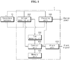
- FIG. 1 is a schematic diagram showing the functional configuration of an apparatus for estimating the state of a secondary battery according to an embodiment of the present disclosure and connection with the secondary battery.
- the apparatus 1 for estimating the state of a secondary battery includes a charging unit 100, a voltage measuring unit 200, a time measuring unit 300 and a control unit 400.
- the charging unit 100 may be electrically connected to two terminals of the secondary battery 10. Particularly, the charging unit 100 according to the present disclosure may be electrically connected to two terminals of the secondary battery 10 to supply the charge power to the secondary battery 10. For example, as shown in the configuration of FIG. 1 , the charging unit 100 may be electrically connected to each of the positive terminal and the negative terminal of the secondary battery 10 to supply the charge power to the secondary battery 10.
- the charging unit 100 may charge the secondary battery 10. Particularly, when the voltage of the secondary battery 10 corresponds to a predefined voltage, the charging unit 100 may start charging the secondary battery 10. Additionally, when the voltage of the secondary battery 10 corresponds to a predefined voltage, the charging unit 100 may terminate the charging of the secondary battery 10. In more detail, the charging unit 100 may charge the secondary battery 10 from a predetermined charge start voltage until the voltage of the secondary battery 10 reaches a predetermined charge end voltage.
- the charging unit 100 may be provided in a hybrid electric vehicle or an electric vehicle, and may be supplied with charge power from the hybrid electric vehicle or the electric vehicle.
- the charging unit 100 may be provided in a secondary battery test apparatus, and may be supplied with charge power from an external power source.
- the voltage measuring unit 200 may be electrically connected to the two terminals of the secondary battery 10. Additionally, the voltage measuring unit 200 according to the present disclosure may measure the voltage across the two terminals of the secondary battery 10.
- the voltage measuring unit 200 may measure the voltage across the two terminals of the secondary battery 10 when the charge/discharge current continuously flows in or out of the secondary battery 10.
- the voltage measuring unit 200 may measure the voltage across the two terminals of the secondary battery 10 when the charge current is continuously supplied from the charging unit 100 to the secondary battery 10.
- the voltage measuring unit 200 may measure the voltage across the two terminals of the secondary battery 10 while the hybrid electric vehicle or the electric vehicle is driving.
- the time measuring unit 300 may measure the charge time of the secondary battery 10. Particularly, the time measuring unit 300 may measure the charge time of the secondary battery 10 multiple times sequentially at a time interval. Additionally, the time measuring unit 300 may be electrically connected to the voltage measuring unit 200 to transmit and receive an electrical signal to/from the voltage measuring unit 200. Here, the time measuring unit 300 may receive a voltage value of the secondary battery 10 from the voltage measuring unit 200.
- the time measuring unit 300 may measure the charge time of the secondary battery 10 in a predefined voltage range during charging of the secondary battery 10. In more detail, during charging of the secondary battery 10, in a predefined voltage range between the charge start voltage and the charge end voltage, the time measuring unit 300 may be configured to measure the charge time of the secondary battery 10 corresponding to the voltage range multiple times.
- the control unit 400 may be configured to estimate the state of the secondary battery 10. Additionally, the control unit 400 may be electrically connected to each of the charging unit 100, the voltage measuring unit 200 and the time measuring unit 300 to transmit and receive an electrical signal to/from the charging unit 100, the voltage measuring unit 200 and the time measuring unit 300.
- control unit 400 may calculate a ratio of charge time. Particularly, the control unit 400 may calculate a ratio of a plurality of charge times measured sequentially at a time interval. In more detail, the control unit 400 may calculate a ratio of a first charge time and a second charge time measured by the time measuring unit 300 sequentially at a time interval. To this end, the control unit 400 may receive the plurality of charge times from the time measuring unit 300. In more detail, the control unit 400 may receive the first charge time and the second charge time from the time measuring unit 300.
- the control unit 400 may estimate the state of the secondary battery 10 using the calculated ratio of charge time. Its detailed description will be provided below. Meanwhile, to perform the above-described operation, the control unit 400 may selectively include a processor, an Application-Specific Integrated Circuit (ASIC), a chipset, a logic circuit, register, a communication modem and/or a data processing device, known in the art.
- ASIC Application-Specific Integrated Circuit
- the apparatus 1 for estimating the state of a secondary battery may further include a memory unit 500.
- the memory unit 500 may pre-store the degradation level of the secondary battery 10. Particularly, the memory unit 500 may pre-store the degradation level of the secondary battery 10 corresponding to the ratio of charge time. In more detail, the memory unit 500 may pre-store the degradation level of the secondary battery 10 corresponding to a ratio of the second charge time to the first charge time sequentially measured at a time interval.
- the memory unit 500 is not limited to a particular type, and includes any type of storage medium that can record and erase information.
- the memory unit 500 may be RAM, ROM, register, hard disk, an optical recording medium or a magnetic recording medium.
- the memory unit 500 may be electrically connected to the control unit 400 through, for example, a data bus, to allow the control unit 400 to access.
- the memory unit 500 may store and/or update and/or erase and/or transmit programs including various control logics executed by the control unit 400, and/or data generated when the control logics are executed.
- the apparatus 1 for estimating the state of a secondary battery according to an embodiment of the present disclosure may further include an alarm unit 600.
- the alarm unit 600 may transmit an alarm signal.
- the alarm unit 600 may transmit the alarm signal to an external device or a vehicle.
- the alarm unit 600 may receive an electrical signal from the control unit 400.
- the control unit 400 may transmit a control signal to the alarm unit 600 to allow the alarm unit 600 to transmit the alarm signal.
- the alarm unit 600 may transmit the alarm signal including information associated with the degradation level of the secondary battery 10 to the external device based on the signal received from the control unit 400.
- the alarm unit 600 may transmit a replacement signal including information about the secondary battery 10 that has degraded and needs to be replaced.
- FIG. 2 shows a change in charge time based on the degradation level of the secondary battery connected to the apparatus for estimating the state of a secondary battery according to an embodiment of the present disclosure.
- the secondary battery 10 connected to the apparatus 1 for estimating the state of a secondary battery according to an embodiment of the present disclosure may be charged in a preset voltage range. That is, when the voltage of the secondary battery 10 corresponds to a preset charge start voltage, the charging unit 100 according to the present disclosure may charge the secondary battery 10. For example, as shown in the graph of FIG. 2 , when the voltage of the secondary battery 10 corresponds to VI, the charging unit 100 may charge the secondary battery 10.
- the charging unit 100 may terminate the charging of the secondary battery 10. For example, as shown in the graph of FIG. 2 , when the voltage of the secondary battery 10 reaches V2, the charging unit 100 may terminate the charging of the secondary battery 10.
- the apparatus 1 for estimating the state of a secondary battery may estimate the state of the secondary battery 10 at a time interval. That is, the apparatus 1 for estimating the state of a secondary battery may measure the charge time of the secondary battery 10 sequentially at a time interval, and estimate the state of the secondary battery 10 using the measured charge times.
- the time measuring unit 300 may measure the charge time corresponding to the predefined voltage range between the charge start voltage and the charge end voltage multiple times. For example, as shown in the graph of FIG. 2 , the time measuring unit 300 may measure the charge time multiple times in the voltage range between V1 and V2. In the embodiment of FIG. 2 , the time measuring unit 300 may measure a plurality of charge times corresponding to a1, b1 and c1. For example, the control unit 400 may receive the plurality of charge times from the time measuring unit 300, and estimate the degradation level of the secondary battery 10 according to the charge times. For example, as the charge time is shorter, the degradation level of the secondary battery 10 may increase. That is, the degradation level of the secondary battery 10 shown in the graph of FIG. 2 gradually increases in the order of c1, b1 and a1. That is, when the charge time is measured at a time interval for one secondary battery 10, the charge times decrease in the order of c1, b1 and a1.
- the secondary battery 10 connected to the apparatus 1 for estimating the state of a secondary battery may be charged in a preset voltage range.
- the voltage range may include a first voltage range in which a constant charge current is maintained, and a second voltage range in which a constant charge voltage is maintained.
- the time measuring unit 300 may measure the charge time of the secondary battery 10 corresponding to each of the first voltage range and the second voltage range.
- the total charge time including the first voltage range and the second voltage range is shorter as the secondary battery 10 degrades.
- a range in which the charge time is 0 ⁇ a1 may correspond to the first voltage range in which a constant charge current is maintained.
- a range in which the charge time is a2 may correspond to the second voltage range in which a constant charge voltage is maintained.
- the charge time of the first voltage range decreases in the order of c1, b1 and a1
- the charge time of the second voltage range increases in the order of c2, b2 and a2.
- the total charge time including the first voltage range and the second voltage range decreases in the order of c1+c2, b1+b2 and a1+a2.
- the control unit 400 may calculate a ratio of a plurality of charge times measured at a time interval in a predefined voltage range.
- the control unit 400 may calculate a ratio of a plurality of charge times measured at a time interval in the first voltage range.
- the control unit 400 may calculate a ratio of a plurality of charge times measured at a time interval in the second voltage range.
- the control unit 400 may calculate a ratio of a1, b1 and c1 measured at a time interval in the first voltage range.
- the control unit 400 may calculate a ratio of a2, b2 and c2 measured at a time interval in the second voltage range.
- the control unit 400 may set the charge time at the point of product sale of the secondary battery 10 as the first charge time and the charge time measured at a time interval from the first charge time as the second charge time, and calculate a ratio of the second charge time to the first charge time.
- the charge time at the point of product sale of the secondary battery 10 may refer to the charge time of the secondary battery 10 at Beginning Of Life (BOL).
- BOL Beginning Of Life
- the control unit 400 may set c1 as the first charge time, and b1 or a1 as the second charge time.
- the control unit 400 may calculate a ratio of b1 to c1 or a ratio of a1 to c1.
- the control unit 400 may set c2 as the first charge time, and b2 or a2 as the second charge time.
- the control unit 400 may calculate a ratio of b2 to c2 or a ratio of a2 to c2.
- the apparatus for estimating the state of a secondary battery may estimate the state of the secondary battery quickly by comparing the charge times of a preset voltage range.
- the apparatus 1 for estimating the state of a secondary battery according to an embodiment of the present disclosure does not uniformly apply the first charge time as a specific value, and may measure the charge time at the initial state (the state at the point of product sale) for each secondary battery 10, and determine the first charge time of each secondary battery 10. That is, because the initial state (the state at the point of product sale) of the secondary battery 10 may differ due to a resistance deviation or a capacity deviation, the apparatus 1 for estimating the state of a secondary battery according to an embodiment of the present disclosure may estimate the current state of each secondary battery 10 more accurately than when the specific value is uniformly applied as the first charge time of the secondary battery 10.
- FIG. 3 shows a change in charge time based on the degradation level of the secondary battery connected to the apparatus for estimating the state of a secondary battery according to another embodiment of the present disclosure.
- the secondary battery 10 connected to the apparatus 1 for estimating the state of a secondary battery according to the present disclosure may be charged and discharged in a preset voltage range.
- the secondary battery 10 connected to the apparatus 1 for estimating the state of a secondary battery may be charged and discharged.
- the graph shown in FIG. 3 shows two measurement times measured at a time interval while the secondary battery 10 is charged and discharged in a preset voltage range V1 ⁇ V2.
- the measurement time t1 and the measurement time t2 are measured at a considerable time interval. For example, there may be a one year time interval between the measurement time t1 and the measurement time t2.
- the time measuring unit 300 may measure the charge time of the secondary battery 10 in the voltage range Va ⁇ Vb corresponding to a predefined voltage range.
- the time measuring unit 300 may measure t1, and measure t2 at a time interval from t1.
- the control unit 400 may calculate a ratio of t2 to t1, and estimate the degradation level of the secondary battery 10 using the calculated ratio. That is, the control unit 400 may estimate the degradation level of the secondary battery 10 according to the ratio of t1 to t2 based on the degradation level pre-stored in the memory unit 500.
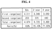
- FIG. 4 shows a change in charge time and a change in ratio of charge time of the secondary battery according to an embodiment of the present disclosure.
- the memory unit 500 may pre-store the degradation level of the secondary battery 10 corresponding to the ratio of charge time.
- the memory unit 500 may store the plurality of charge times received from the time measuring unit 300.
- the memory unit 500 may store the charge time corresponding to the voltage range and the ratio of charge time.
- the BOL charge time of the secondary battery 10 may be 4,611s in the first range, and 263s in the second range.
- the charge time of the total range including the first range and the second range may be 4,874s.
- the charge time after two year use of the secondary battery 10 may be 3,349s in the first range, and 376s in the second range.
- the charge time of the total range including the first range and the second range may be 3,725s.
- the charge time after four year use of the secondary battery 10 may be 3,050s in the first range, and 440s in the second range.
- the charge time of the total range including the first range and the second range may be 3,490s.
- the control unit 400 may receive the charge time of the voltage range from the memory unit 500, and calculate a ratio of charge time. For example, in the embodiment of FIG. 4 , when the BOL charge time of the secondary battery 10 is set to 100%, the charge time after two year use of the secondary battery 10 to the BOL charge time of the secondary battery 10 may be 76.43%, and the charge time after four year use of the secondary battery 10 to the BOL charge time of the secondary battery 10 may be 71.60%.
- the control unit 400 may calculate a ratio of charge time for the first range and a ratio of charge time for the second range. Alternatively, the control unit 400 may calculate a ratio of charge time for the total range.
- the control unit 400 may determine whether the secondary battery 10 needs to be replaced. Particularly, when a ratio of charge time is a predetermined value or less, the control unit 400 may determine that the secondary battery 10 needs to be replaced. In more detail, when a ratio of the second charge time to the first charge time is a predetermined value or less, the control unit 400 may be configured to transmit a replacement signal for the secondary battery 10. For example, when a ratio of the charge time to the BOL charge time of the secondary battery 10 corresponds to 75%, the control unit 400 may determine that the secondary battery 10 needs to be replaced.
- the predetermined value may be differently determined for each secondary battery 10. That is, the predetermined value may be a value that is set independently for each secondary battery 10 based on the initial state of the secondary battery 10. For example, because the predetermined value is different for each secondary battery 10, even though a ratio of the second charge time to the first charge time of the first secondary battery is equal to a ratio of the second charge time to the first charge time of the second secondary battery, a replacement signal for only the first secondary battery may be transmitted.
- the secondary battery 10 used in emergency call application should always have the discharge capacity enough to supply the specific power.
- the predetermined value may be determined for each secondary battery 10 based on a correlation between the discharge capacity (retained capacity) and the charge time of each secondary battery 10. For example, the predetermined value for the first secondary battery may be 75%, the predetermined value for the second secondary battery may be 78%, and the predetermined value for the third secondary battery may be 76%.
- the control unit 400 may determine that the second secondary battery and the third secondary battery need to be replaced, and transmit a replacement signal for the second secondary battery and the third secondary battery. That is, the apparatus 1 for estimating the state of a secondary battery according to an embodiment of the present disclosure individually determines a reference ratio (a predetermined value) for determining whether the secondary battery 10 needs to be replaced based on the initial state of each secondary battery 10, to measure the state of each secondary battery 10 more precisely and accurately.
- a reference ratio a predetermined value
- the apparatus 1 for estimating the state of a secondary battery determines the state of each secondary battery 10 using the absolute time as well as the ratio of charge time. That is, because the apparatus 1 for estimating the state of a secondary battery uses the ratio of charge time of each secondary battery 10, it is possible to determine the state of each secondary battery 10 irrespective of a difference in resistance or capacity between the secondary batteries 10. For example, when the state of the secondary battery 10 is uniformly determined according to the absolute charge time of the secondary battery 10, because a difference in resistance or capacity between the secondary batteries 10 is not taken into account, the degradation level of each secondary battery 10 cannot be accurately measured. That is, even though the charge time is the same, the degradation level may be different depending on the resistance or capacity of the secondary battery 10. Accordingly, when only the absolute charge time is taken into account, it is impossible to accurately measure the state of the secondary battery 10, and thus the apparatus 1 for estimating the state of a secondary battery may measure the state of each secondary battery 10 more accurately than when only the absolute charge time is used.
- the apparatus 1 for estimating the state of a secondary battery according to the present disclosure may be provided in a battery pack in itself. That is, the battery pack according to the present disclosure may include the above-described apparatus for estimating the state of a secondary battery according to the present disclosure.
- the battery pack may include a plurality of secondary batteries, the apparatus for estimating the state of a secondary battery, an electrical component (a BMS, a relay, a fuse, etc.) and a case.
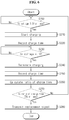
- FIG. 5 is a schematic flowchart showing a method for estimating the state of a secondary battery according to an embodiment of the present disclosure.
- the subject that performs each step may be each component of the previously-described apparatus 1 for estimating the state of a secondary battery according to the present disclosure.
- step S100 the charging unit 100 charges the secondary battery 10.
- step S110 the voltage measuring unit 200 measures the voltage across two terminals of the secondary battery 10.
- step S120 the time measuring unit 300 receives a voltage value of the secondary battery 10, and in a predefined voltage range, measures the charge time of the secondary battery 10 corresponding to the voltage range multiple times during charging of the secondary battery 10.
- step S130 for a first charge time and a second charge time measured sequentially at a time interval, the control unit 400 calculates a ratio of the second charge time to the first charge time, and estimates the state of the secondary battery 10.
- the voltage measuring unit 200 may measure the voltage across the two terminals of the secondary battery 10 when the charge current is continuously supplied from the charging unit 100 to the secondary battery 10.
- control unit 400 may set the charge time at the product sale of the secondary battery 10 as a first charge time and the charge time measured at a time interval from the first charge time as a second charge time, and calculate a ratio of the second charge time to the first charge time.
- FIG. 6 is a schematic flowchart showing a method for estimating the state of a secondary battery according to another embodiment of the present disclosure.
- the subject that performs each step may be each component of the previously-described apparatus 1 for estimating the state of a secondary battery according to the present disclosure.
- the charge start voltage (3.9V), the charge end voltage (4.1V) and the predetermined value (75%) for replacement signal transmission shown in FIG. 6 are just an example, and the method for estimating the state of a secondary battery according to an embodiment of the present disclosure is not limited to these values.
- the control unit 400 may determine whether the voltage of the secondary battery 10 corresponds to a charge start voltage.
- the charge start voltage may be 3.9V.
- control unit 400 may transmit a charge start command to the charging unit 100 to enable the charging unit 100 to charge the secondary battery 10 in step S210.
- the control unit 400 may not charge the secondary battery 10.
- the time measuring unit 300 may record the charge time of the secondary battery 10. Particularly, the time measuring unit 300 may start recording the charge time when the charging starts.
- the control unit 400 may determine whether the voltage of the secondary battery 10 corresponds to a charge end voltage.
- the charge end voltage may be 4.1V.
- control unit 400 may transmit a charge end command to the charging unit 100 to enable the charging unit 100 to terminate the charging of the secondary battery 10 in step S240.
- the control unit 400 may keep charging the secondary battery 10.
- the time measuring unit 300 may record the charge time of the secondary battery 10. Particularly, the time measuring unit 300 may terminate the recording of the charge time when the charging ends.
- control unit 400 may calculate a ratio of charge time.
- control unit 400 may receive the charge time from the memory unit 500 or the time measuring unit 300.
- control unit 400 may determine whether the ratio of charge time corresponds to the time to replace. For example, the control unit 400 may determine that it is time to replace when the ratio of charge time is 75% or less.
- the control unit 400 may transmit a replacement signal transmit command to the alarm unit 600 in step S280. Additionally, the alarm unit 600 may transmit a replacement signal based on the command received from the control unit 400. On the contrary, the determination result of the step S270 is NO, the control unit 400 may revert to the step S200 to determine whether the voltage of the secondary battery 10 corresponds to the charge start voltage.
- control unit 400 may be implemented as a set of program modules.
- program module may be stored in the memory device and executed by the processor.
- control logics of the control unit 400 may be combined, and the combined control logics are not limited to a particular type and include any type that can be written in computer-readable coding systems and read and accessed by the computer.
- the recording media may include at least one selected from the group consisting of ROM, RAM, register, CD-ROM, magnetic tape, hard disk, floppy disk and an optical data recording device.
- the coding systems may be stored and executed in computers connected via a network in distributed manner. Additionally, functional programs, codes and segments for implementing the combined control logics may be easily inferred by programs in the technical field pertaining to the present disclosure.
- 'unit' such as 'memory unit' and 'control unit' is used herein, but this indicates a logical component unit and it is obvious to those skilled in the art that the term does not necessarily indicate a component that may be or should be physically separated from other.
Landscapes
- Physics & Mathematics (AREA)
- General Physics & Mathematics (AREA)
- Engineering & Computer Science (AREA)
- Manufacturing & Machinery (AREA)
- Chemical & Material Sciences (AREA)
- Chemical Kinetics & Catalysis (AREA)
- Electrochemistry (AREA)
- General Chemical & Material Sciences (AREA)
- Power Engineering (AREA)
- Secondary Cells (AREA)
- Charge And Discharge Circuits For Batteries Or The Like (AREA)
- Tests Of Electric Status Of Batteries (AREA)
Abstract
Description
- The present application claims priority to Korean Patent Application No.
10-2018-0016387 - The present disclosure relates to an apparatus and method for estimating the state of a secondary battery, and more particularly, to a secondary battery state estimation apparatus and method for effectively estimating the lifetime or degradation of a secondary battery with secondary battery aging.
- Recently, there is dramatically growing demand for portable electronic products such as laptop computers, video cameras and mobile phones, and with the intense development of electric vehicles, accumulators for energy storage, robots and satellites, many studies are being made on high performance secondary batteries that can be recharged repeatedly.
- Currently, commercially available secondary batteries include nickel-cadmium batteries, nickel-hydrogen batteries, nickel-zinc batteries, lithium secondary batteries and the like, and among them, lithium secondary batteries have little or no memory effect, and thus they are gaining more attention than nickel-based secondary batteries for their advantages of free charging and discharging, a very low self-discharge rate and high energy density.
- The lithium secondary battery mainly uses lithium-based oxide and a carbon material for a positive electrode active material and a negative electrode active material respectively. The lithium secondary battery includes an electrode assembly including a positive electrode plate and a negative electrode plate coated respectively with the positive electrode active material and the negative electrode active material with a separator interposed between, and a packaging material, i.e., a battery case hermetically sealed to receive the electrode assembly therein together with an electrolyte solution.
- In general, lithium secondary batteries may be classified into can-type secondary batteries in which an electrode assembly is embedded in a metal can and pouch-type secondary batteries in which an electrode assembly is embedded in a pouch of an aluminum laminate sheet, according to the shape of the packaging material. These secondary batteries are usually manufactured by receiving the electrode assembly in the packaging material, and in this state, injecting an electrolyte solution, and sealing the packaging material.
- More recently, with the extended application range of secondary batteries, secondary batteries are being widely used in small portable devices including smart phones, as well as medium- and large-scale devices such as electric vehicles including hybrid electric vehicles or energy storage systems.
- In the case of a secondary battery, as the usage period increases, the performance degrades compared to initial state. Additionally, performance degradation estimation of the secondary battery is said to be State Of Health (SOH) estimation of the secondary battery, and the SOH of the secondary battery is an important factor in determining when to replace the secondary battery.
- Additionally, the degradation level may differ in each secondary battery depending on environments in which the secondary battery is manufactured and used. Additionally, in the case of a battery pack including a plurality of secondary batteries, it is necessary to accurately estimate the lifetime of each secondary battery based on the degradation level of each secondary battery. Typically, a Battery Management System (BMS) is required to accurately estimate the lifetime of each secondary battery provided in the battery pack, and based on this, efficiently operate the battery pack.
- The present disclosure is devised under the background of the conventional art, and therefore the present disclosure relates to an improved secondary battery state estimation apparatus and method for effectively estimating the lifetime or degradation of a secondary battery with secondary battery aging.
- These and other objects and advantages of the present disclosure can be understood by the following description and will be apparent from the embodiments of the present disclosure. Additionally, it will be readily understood that the objects and advantages of the present disclosure are realized by the means set forth in the appended claims and combinations thereof.
- To achieve the above-described object, an apparatus for estimating a state of a secondary battery according to an embodiment of the present disclosure includes a charging unit electrically connected to two terminals of the secondary battery to charge the secondary battery, a voltage measuring unit electrically connected to the two terminals of the secondary battery to measure a voltage across the two terminals of the secondary battery, a time measuring unit configured to receive a voltage value of the secondary battery from the voltage measuring unit, and during charging of the secondary battery, in a predefined voltage range, measure a charge time of the secondary battery corresponding to the voltage range multiple times, and a control unit configured to transmit and receive an electrical signal to/from the charging unit, the voltage measuring unit and the time measuring unit, calculate a ratio of a first charge time and a second charge time measured by the time measuring unit sequentially at a time interval and estimate a state of the secondary battery.
- Additionally, the voltage measuring unit may measure the voltage across the two terminals of the secondary battery when a charge current is continuously supplied from the charging unit to the secondary battery.
- Additionally, the apparatus for estimating a state of a secondary battery according to an embodiment of the present disclosure may further include a memory unit configured to pre-store a degradation level of the secondary battery corresponding to the ratio of the second charge time to the first charge time.
- Additionally, the apparatus for estimating a state of a secondary battery according to an embodiment of the present disclosure may further include an alarm unit configured to receive an electrical signal from the control unit, and transmit an alarm signal including information associated with a degradation level of the secondary battery to an external device based on the signal received from the control unit.
- Additionally, the voltage range may include a first voltage range in which a constant charge current is maintained and a second voltage range in which a constant charge voltage is maintained, and the time measuring unit may be configured to measure the charge time of the secondary battery corresponding to each of the first voltage range and the second voltage range.
- Additionally, the control unit may be configured to calculate a ratio of a plurality of charge times measured at a time interval in the first voltage range or a plurality of charge times measured at a time interval in the second voltage range.
- Additionally, the control unit may be configured to set a charge time at a point of product sale of the secondary battery as the first charge time and a charge time measured at a time interval from the first charge time as the second charge time, and calculate a ratio of the second charge time to the first charge time.
- Additionally, the control unit may be configured to transmit a replacement signal for the secondary battery when a ratio of the second charge time to the first charge time is a predetermined value or less.
- Additionally, a battery pack according to an embodiment of the present disclosure includes the apparatus for estimating a state of a secondary battery according to the present disclosure.
- Additionally, to achieve the above-described object, a method for estimating a state of a secondary battery according to an embodiment of the present disclosure includes charging the secondary battery, measuring a voltage across two terminals of the secondary battery, receiving a voltage value of the secondary battery, and during charging of the secondary battery, in a predefined voltage range, measuring a charge time of the secondary battery corresponding to the voltage range multiple times, and for a first charge time and a second charge time measured sequentially at a time interval, calculating a ratio of the second charge time to the first charge time and estimating a state of the secondary battery.
- According to an aspect of the present disclosure, the apparatus for estimating the state of a secondary battery measures the charge time of the secondary battery and uses a ratio between a plurality of charge times to estimate the degradation level of the secondary battery, thereby estimating the degradation level of the secondary battery in an easy and simple manner.
- Particularly, as opposed to the conventional art considering the absolute charge time, the apparatus for estimating the state of a secondary battery according to an aspect of the present disclosure may use a ratio of charge time. The conventional art considering the absolute charge time is difficult to accurately estimate the state of a secondary battery due to process deviations in the manufacture of the secondary battery. Accordingly, the apparatus for estimating the state of a secondary battery according to the present disclosure may accurately estimate the degradation level of the secondary battery using a ratio of charge time.
- The present disclosure may have a variety of other effects, and these and other effects of the present disclosure can be understood by the following description and will be apparent from the embodiments of the present disclosure.
- The accompanying drawings illustrate a preferred embodiment of the present disclosure, and together with the detailed description of the present disclosure described below, serve to provide a further understanding of the technical aspects of the present disclosure, and thus the present disclosure should not be construed as being limited to the drawings.
-
FIG. 1 is a schematic diagram showing the functional configuration of an apparatus for estimating the state of a secondary battery according to an embodiment of the present disclosure and connection with the secondary battery. -
FIG. 2 shows a change in charge time based on the degradation level of a secondary battery connected to an apparatus for estimating the state of a secondary battery according to an embodiment of the present disclosure. -
FIG. 3 shows a change in charge time based on the degradation level of a secondary battery connected to an apparatus for estimating the state of a secondary battery according to another embodiment of the present disclosure. -
FIG. 4 shows a change in charge time and a change in ratio of charge time of a secondary battery according to an embodiment of the present disclosure. -
FIG. 5 is a schematic flowchart showing a method for estimating the state of a secondary battery according to an embodiment of the present disclosure. -
FIG. 6 is a schematic flowchart showing a method for estimating the state of a secondary battery according to another embodiment of the present disclosure. - Hereinafter, the preferred embodiments of the present disclosure will be described in detail with reference to the accompanying drawings. Prior to the description, it should be understood that the terms or words used in the specification and the appended claims should not be construed as limited to general and dictionary meanings, but interpreted based on the meanings and concepts corresponding to technical aspects of the present disclosure on the basis of the principle that the inventor is allowed to define terms appropriately for the best explanation.
- Therefore, the embodiments described herein and illustrations shown in the drawings are just a most preferred embodiment of the present disclosure, but not intended to fully describe the technical aspects of the present disclosure, so it should be understood that a variety of other equivalents and modifications could be made thereto at the time of filing the application.
- Additionally, in describing the present disclosure, when it is deemed that a certain detailed description of relevant known elements or functions renders the key subject matter of the present disclosure ambiguous, the detailed description is omitted herein.
- Unless the context clearly indicates otherwise, it will be understood that the term "comprises" or "includes" when used in this specification, specifies the presence of stated elements, but does not preclude the presence or addition of one or more other elements. Additionally, the term 'control unit' as used herein refers to a processing unit of at least one function or operation, and this may be implemented by hardware or software alone or in combination.
- In addition, throughout the specification, it will be further understood that when an element is referred to as being "connected to" another element, it can be directly connected to the other element or intervening elements may be present.
- In the specification, a secondary battery refers to a physically separable independent secondary battery including a negative terminal and a positive terminal. For example, a pouch-type lithium polymer cell may be regarded as a secondary battery.
-
FIG. 1 is a schematic diagram showing the functional configuration of an apparatus for estimating the state of a secondary battery according to an embodiment of the present disclosure and connection with the secondary battery. - Referring to
FIG. 1 , theapparatus 1 for estimating the state of a secondary battery according to the present disclosure includes acharging unit 100, avoltage measuring unit 200, atime measuring unit 300 and acontrol unit 400. - The
charging unit 100 may be electrically connected to two terminals of thesecondary battery 10. Particularly, thecharging unit 100 according to the present disclosure may be electrically connected to two terminals of thesecondary battery 10 to supply the charge power to thesecondary battery 10. For example, as shown in the configuration ofFIG. 1 , thecharging unit 100 may be electrically connected to each of the positive terminal and the negative terminal of thesecondary battery 10 to supply the charge power to thesecondary battery 10. - The
charging unit 100 may charge thesecondary battery 10. Particularly, when the voltage of thesecondary battery 10 corresponds to a predefined voltage, thecharging unit 100 may start charging thesecondary battery 10. Additionally, when the voltage of thesecondary battery 10 corresponds to a predefined voltage, thecharging unit 100 may terminate the charging of thesecondary battery 10. In more detail, thecharging unit 100 may charge thesecondary battery 10 from a predetermined charge start voltage until the voltage of thesecondary battery 10 reaches a predetermined charge end voltage. - The
charging unit 100 according to an embodiment of the present disclosure may be provided in a hybrid electric vehicle or an electric vehicle, and may be supplied with charge power from the hybrid electric vehicle or the electric vehicle. - The charging
unit 100 according to another embodiment of the present disclosure may be provided in a secondary battery test apparatus, and may be supplied with charge power from an external power source. - The
voltage measuring unit 200 may be electrically connected to the two terminals of thesecondary battery 10. Additionally, thevoltage measuring unit 200 according to the present disclosure may measure the voltage across the two terminals of thesecondary battery 10. - Preferably, the
voltage measuring unit 200 according to the present disclosure may measure the voltage across the two terminals of thesecondary battery 10 when the charge/discharge current continuously flows in or out of thesecondary battery 10. Particularly, thevoltage measuring unit 200 may measure the voltage across the two terminals of thesecondary battery 10 when the charge current is continuously supplied from the chargingunit 100 to thesecondary battery 10. For example, thevoltage measuring unit 200 may measure the voltage across the two terminals of thesecondary battery 10 while the hybrid electric vehicle or the electric vehicle is driving. - The
time measuring unit 300 may measure the charge time of thesecondary battery 10. Particularly, thetime measuring unit 300 may measure the charge time of thesecondary battery 10 multiple times sequentially at a time interval. Additionally, thetime measuring unit 300 may be electrically connected to thevoltage measuring unit 200 to transmit and receive an electrical signal to/from thevoltage measuring unit 200. Here, thetime measuring unit 300 may receive a voltage value of thesecondary battery 10 from thevoltage measuring unit 200. - Additionally, the
time measuring unit 300 may measure the charge time of thesecondary battery 10 in a predefined voltage range during charging of thesecondary battery 10. In more detail, during charging of thesecondary battery 10, in a predefined voltage range between the charge start voltage and the charge end voltage, thetime measuring unit 300 may be configured to measure the charge time of thesecondary battery 10 corresponding to the voltage range multiple times. - The
control unit 400 may be configured to estimate the state of thesecondary battery 10. Additionally, thecontrol unit 400 may be electrically connected to each of the chargingunit 100, thevoltage measuring unit 200 and thetime measuring unit 300 to transmit and receive an electrical signal to/from the chargingunit 100, thevoltage measuring unit 200 and thetime measuring unit 300. - Additionally, the
control unit 400 may calculate a ratio of charge time. Particularly, thecontrol unit 400 may calculate a ratio of a plurality of charge times measured sequentially at a time interval. In more detail, thecontrol unit 400 may calculate a ratio of a first charge time and a second charge time measured by thetime measuring unit 300 sequentially at a time interval. To this end, thecontrol unit 400 may receive the plurality of charge times from thetime measuring unit 300. In more detail, thecontrol unit 400 may receive the first charge time and the second charge time from thetime measuring unit 300. - The
control unit 400 may estimate the state of thesecondary battery 10 using the calculated ratio of charge time. Its detailed description will be provided below. Meanwhile, to perform the above-described operation, thecontrol unit 400 may selectively include a processor, an Application-Specific Integrated Circuit (ASIC), a chipset, a logic circuit, register, a communication modem and/or a data processing device, known in the art. - Preferably, the
apparatus 1 for estimating the state of a secondary battery according to an embodiment of the present disclosure may further include amemory unit 500. - The
memory unit 500 may pre-store the degradation level of thesecondary battery 10. Particularly, thememory unit 500 may pre-store the degradation level of thesecondary battery 10 corresponding to the ratio of charge time. In more detail, thememory unit 500 may pre-store the degradation level of thesecondary battery 10 corresponding to a ratio of the second charge time to the first charge time sequentially measured at a time interval. - Additionally, the
memory unit 500 is not limited to a particular type, and includes any type of storage medium that can record and erase information. For example, thememory unit 500 may be RAM, ROM, register, hard disk, an optical recording medium or a magnetic recording medium. Additionally, thememory unit 500 may be electrically connected to thecontrol unit 400 through, for example, a data bus, to allow thecontrol unit 400 to access. Additionally, thememory unit 500 may store and/or update and/or erase and/or transmit programs including various control logics executed by thecontrol unit 400, and/or data generated when the control logics are executed. - Additionally, preferably, the
apparatus 1 for estimating the state of a secondary battery according to an embodiment of the present disclosure may further include analarm unit 600. - The
alarm unit 600 may transmit an alarm signal. For example, thealarm unit 600 may transmit the alarm signal to an external device or a vehicle. Additionally, thealarm unit 600 may receive an electrical signal from thecontrol unit 400. Here, thecontrol unit 400 may transmit a control signal to thealarm unit 600 to allow thealarm unit 600 to transmit the alarm signal. In more detail, thealarm unit 600 may transmit the alarm signal including information associated with the degradation level of thesecondary battery 10 to the external device based on the signal received from thecontrol unit 400. For example, thealarm unit 600 may transmit a replacement signal including information about thesecondary battery 10 that has degraded and needs to be replaced. -
FIG. 2 shows a change in charge time based on the degradation level of the secondary battery connected to the apparatus for estimating the state of a secondary battery according to an embodiment of the present disclosure. - Referring to
FIG. 2 , thesecondary battery 10 connected to theapparatus 1 for estimating the state of a secondary battery according to an embodiment of the present disclosure may be charged in a preset voltage range. That is, when the voltage of thesecondary battery 10 corresponds to a preset charge start voltage, the chargingunit 100 according to the present disclosure may charge thesecondary battery 10. For example, as shown in the graph ofFIG. 2 , when the voltage of thesecondary battery 10 corresponds to VI, the chargingunit 100 may charge thesecondary battery 10. - Additionally, when the voltage of the
secondary battery 10 reaches a preset charge end voltage, the chargingunit 100 may terminate the charging of thesecondary battery 10. For example, as shown in the graph ofFIG. 2 , when the voltage of thesecondary battery 10 reaches V2, the chargingunit 100 may terminate the charging of thesecondary battery 10. - The
apparatus 1 for estimating the state of a secondary battery according to an embodiment of the present disclosure may estimate the state of thesecondary battery 10 at a time interval. That is, theapparatus 1 for estimating the state of a secondary battery may measure the charge time of thesecondary battery 10 sequentially at a time interval, and estimate the state of thesecondary battery 10 using the measured charge times. - Additionally, the
time measuring unit 300 may measure the charge time corresponding to the predefined voltage range between the charge start voltage and the charge end voltage multiple times. For example, as shown in the graph ofFIG. 2 , thetime measuring unit 300 may measure the charge time multiple times in the voltage range between V1 and V2. In the embodiment ofFIG. 2 , thetime measuring unit 300 may measure a plurality of charge times corresponding to a1, b1 and c1. For example, thecontrol unit 400 may receive the plurality of charge times from thetime measuring unit 300, and estimate the degradation level of thesecondary battery 10 according to the charge times. For example, as the charge time is shorter, the degradation level of thesecondary battery 10 may increase. That is, the degradation level of thesecondary battery 10 shown in the graph ofFIG. 2 gradually increases in the order of c1, b1 and a1. That is, when the charge time is measured at a time interval for onesecondary battery 10, the charge times decrease in the order of c1, b1 and a1. - The
secondary battery 10 connected to theapparatus 1 for estimating the state of a secondary battery according to an embodiment of the present disclosure may be charged in a preset voltage range. Here, the voltage range may include a first voltage range in which a constant charge current is maintained, and a second voltage range in which a constant charge voltage is maintained. Here, thetime measuring unit 300 may measure the charge time of thesecondary battery 10 corresponding to each of the first voltage range and the second voltage range. - Because the internal resistance increases with aging of the
secondary battery 10, as thesecondary battery 10 degrades, there is a reduction in the charge time of the first voltage range in which a constant charge current is maintained, and there is an increase in the charge time of the second voltage range in which a constant charge voltage is maintained. However, the total charge time including the first voltage range and the second voltage range is shorter as thesecondary battery 10 degrades. - For example, in the voltage-time graph shown in
FIG. 2 , when the charge time of the voltage range V1∼V2 corresponds to a1, a range in which the charge time is 0∼a1 may correspond to the first voltage range in which a constant charge current is maintained. Additionally, a range in which the charge time is a2 may correspond to the second voltage range in which a constant charge voltage is maintained. For example, as the degradation level of thesecondary battery 10 increases, the charge time of the first voltage range decreases in the order of c1, b1 and a1, and the charge time of the second voltage range increases in the order of c2, b2 and a2. However, the total charge time including the first voltage range and the second voltage range decreases in the order of c1+c2, b1+b2 and a1+a2. - Preferably, the
control unit 400 according to an embodiment of the present disclosure may calculate a ratio of a plurality of charge times measured at a time interval in a predefined voltage range. In more detail, thecontrol unit 400 may calculate a ratio of a plurality of charge times measured at a time interval in the first voltage range. Alternatively, thecontrol unit 400 may calculate a ratio of a plurality of charge times measured at a time interval in the second voltage range. For example, in the embodiment ofFIG. 2 , thecontrol unit 400 may calculate a ratio of a1, b1 and c1 measured at a time interval in the first voltage range. Additionally, thecontrol unit 400 may calculate a ratio of a2, b2 and c2 measured at a time interval in the second voltage range. - Additionally, preferably, the
control unit 400 according to an embodiment of the present disclosure may set the charge time at the point of product sale of thesecondary battery 10 as the first charge time and the charge time measured at a time interval from the first charge time as the second charge time, and calculate a ratio of the second charge time to the first charge time. Here, the charge time at the point of product sale of thesecondary battery 10 may refer to the charge time of thesecondary battery 10 at Beginning Of Life (BOL). For example, in the embodiment ofFIG. 2 , thecontrol unit 400 may set c1 as the first charge time, and b1 or a1 as the second charge time. Additionally, thecontrol unit 400 may calculate a ratio of b1 to c1 or a ratio of a1 to c1. Alternatively, thecontrol unit 400 may set c2 as the first charge time, and b2 or a2 as the second charge time. Additionally, thecontrol unit 400 may calculate a ratio of b2 to c2 or a ratio of a2 to c2. - According to this configuration of the present disclosure, the apparatus for estimating the state of a secondary battery according to the present disclosure may estimate the state of the secondary battery quickly by comparing the charge times of a preset voltage range.
- Additionally, the
apparatus 1 for estimating the state of a secondary battery according to an embodiment of the present disclosure does not uniformly apply the first charge time as a specific value, and may measure the charge time at the initial state (the state at the point of product sale) for eachsecondary battery 10, and determine the first charge time of eachsecondary battery 10. That is, because the initial state (the state at the point of product sale) of thesecondary battery 10 may differ due to a resistance deviation or a capacity deviation, theapparatus 1 for estimating the state of a secondary battery according to an embodiment of the present disclosure may estimate the current state of eachsecondary battery 10 more accurately than when the specific value is uniformly applied as the first charge time of thesecondary battery 10. -
FIG. 3 shows a change in charge time based on the degradation level of the secondary battery connected to the apparatus for estimating the state of a secondary battery according to another embodiment of the present disclosure. - Referring to
FIG. 3 , thesecondary battery 10 connected to theapparatus 1 for estimating the state of a secondary battery according to the present disclosure may be charged and discharged in a preset voltage range. For example, when a hybrid electric vehicle or an electric vehicle drives, thesecondary battery 10 connected to theapparatus 1 for estimating the state of a secondary battery may be charged and discharged. - The graph shown in
FIG. 3 shows two measurement times measured at a time interval while thesecondary battery 10 is charged and discharged in a preset voltage range V1∼V2. Here, assume that the measurement time t1 and the measurement time t2 are measured at a considerable time interval. For example, there may be a one year time interval between the measurement time t1 and the measurement time t2. - Here, the
time measuring unit 300 may measure the charge time of thesecondary battery 10 in the voltage range Va∼Vb corresponding to a predefined voltage range. In more detail, in the voltage range Va∼Vb, thetime measuring unit 300 may measure t1, and measure t2 at a time interval from t1. In this configuration, thecontrol unit 400 may calculate a ratio of t2 to t1, and estimate the degradation level of thesecondary battery 10 using the calculated ratio. That is, thecontrol unit 400 may estimate the degradation level of thesecondary battery 10 according to the ratio of t1 to t2 based on the degradation level pre-stored in thememory unit 500. -
FIG. 4 shows a change in charge time and a change in ratio of charge time of the secondary battery according to an embodiment of the present disclosure. - As shown in
FIG. 4 , thememory unit 500 according to an embodiment of the present disclosure may pre-store the degradation level of thesecondary battery 10 corresponding to the ratio of charge time. In this instance, thememory unit 500 may store the plurality of charge times received from thetime measuring unit 300. - Referring to
FIGS. 1 and4 , thememory unit 500 may store the charge time corresponding to the voltage range and the ratio of charge time. For example, the BOL charge time of thesecondary battery 10 may be 4,611s in the first range, and 263s in the second range. Here, the charge time of the total range including the first range and the second range may be 4,874s. Additionally, the charge time after two year use of thesecondary battery 10 may be 3,349s in the first range, and 376s in the second range. Here, the charge time of the total range including the first range and the second range may be 3,725s. Additionally, the charge time after four year use of thesecondary battery 10 may be 3,050s in the first range, and 440s in the second range. Here, the charge time of the total range including the first range and the second range may be 3,490s. - The
control unit 400 may receive the charge time of the voltage range from thememory unit 500, and calculate a ratio of charge time. For example, in the embodiment ofFIG. 4 , when the BOL charge time of thesecondary battery 10 is set to 100%, the charge time after two year use of thesecondary battery 10 to the BOL charge time of thesecondary battery 10 may be 76.43%, and the charge time after four year use of thesecondary battery 10 to the BOL charge time of thesecondary battery 10 may be 71.60%. Thecontrol unit 400 may calculate a ratio of charge time for the first range and a ratio of charge time for the second range. Alternatively, thecontrol unit 400 may calculate a ratio of charge time for the total range. - Preferably, the
control unit 400 may determine whether thesecondary battery 10 needs to be replaced. Particularly, when a ratio of charge time is a predetermined value or less, thecontrol unit 400 may determine that thesecondary battery 10 needs to be replaced. In more detail, when a ratio of the second charge time to the first charge time is a predetermined value or less, thecontrol unit 400 may be configured to transmit a replacement signal for thesecondary battery 10. For example, when a ratio of the charge time to the BOL charge time of thesecondary battery 10 corresponds to 75%, thecontrol unit 400 may determine that thesecondary battery 10 needs to be replaced. - Here, the predetermined value may be differently determined for each
secondary battery 10. That is, the predetermined value may be a value that is set independently for eachsecondary battery 10 based on the initial state of thesecondary battery 10. For example, because the predetermined value is different for eachsecondary battery 10, even though a ratio of the second charge time to the first charge time of the first secondary battery is equal to a ratio of the second charge time to the first charge time of the second secondary battery, a replacement signal for only the first secondary battery may be transmitted. - Describing as a specific example, in the case of emergency call application, it is necessary to supply a specific power to prepare for an emergent situation. Accordingly, the
secondary battery 10 used in emergency call application should always have the discharge capacity enough to supply the specific power. However, because the initial state may be different for eachsecondary battery 10 depending on the initial capacity and the resistance deviation of thesecondary battery 10, the predetermined value may be determined for eachsecondary battery 10 based on a correlation between the discharge capacity (retained capacity) and the charge time of eachsecondary battery 10. For example, the predetermined value for the first secondary battery may be 75%, the predetermined value for the second secondary battery may be 78%, and the predetermined value for the third secondary battery may be 76%. In this instance, if it is assumed that the ratios of the second charge time to the first charge time of the first to third secondary batteries are all 76%, thecontrol unit 400 may determine that the second secondary battery and the third secondary battery need to be replaced, and transmit a replacement signal for the second secondary battery and the third secondary battery. That is, theapparatus 1 for estimating the state of a secondary battery according to an embodiment of the present disclosure individually determines a reference ratio (a predetermined value) for determining whether thesecondary battery 10 needs to be replaced based on the initial state of eachsecondary battery 10, to measure the state of eachsecondary battery 10 more precisely and accurately. - Additionally, the
apparatus 1 for estimating the state of a secondary battery according to an embodiment of the present disclosure determines the state of eachsecondary battery 10 using the absolute time as well as the ratio of charge time. That is, because theapparatus 1 for estimating the state of a secondary battery uses the ratio of charge time of eachsecondary battery 10, it is possible to determine the state of eachsecondary battery 10 irrespective of a difference in resistance or capacity between thesecondary batteries 10. For example, when the state of thesecondary battery 10 is uniformly determined according to the absolute charge time of thesecondary battery 10, because a difference in resistance or capacity between thesecondary batteries 10 is not taken into account, the degradation level of eachsecondary battery 10 cannot be accurately measured. That is, even though the charge time is the same, the degradation level may be different depending on the resistance or capacity of thesecondary battery 10. Accordingly, when only the absolute charge time is taken into account, it is impossible to accurately measure the state of thesecondary battery 10, and thus theapparatus 1 for estimating the state of a secondary battery may measure the state of eachsecondary battery 10 more accurately than when only the absolute charge time is used. - The
apparatus 1 for estimating the state of a secondary battery according to the present disclosure may be provided in a battery pack in itself. That is, the battery pack according to the present disclosure may include the above-described apparatus for estimating the state of a secondary battery according to the present disclosure. Here, the battery pack may include a plurality of secondary batteries, the apparatus for estimating the state of a secondary battery, an electrical component (a BMS, a relay, a fuse, etc.) and a case. -
FIG. 5 is a schematic flowchart showing a method for estimating the state of a secondary battery according to an embodiment of the present disclosure. InFIG. 5 , the subject that performs each step may be each component of the previously-describedapparatus 1 for estimating the state of a secondary battery according to the present disclosure. - As shown in
FIGS. 1 and5 , according to the method for estimating the state of a secondary battery according to the present disclosure, in step S100, the chargingunit 100 charges thesecondary battery 10. - Subsequently, in step S110, the
voltage measuring unit 200 measures the voltage across two terminals of thesecondary battery 10. - Subsequently, in step S120, the
time measuring unit 300 receives a voltage value of thesecondary battery 10, and in a predefined voltage range, measures the charge time of thesecondary battery 10 corresponding to the voltage range multiple times during charging of thesecondary battery 10. - Subsequently, in step S130, for a first charge time and a second charge time measured sequentially at a time interval, the
control unit 400 calculates a ratio of the second charge time to the first charge time, and estimates the state of thesecondary battery 10. - Preferably, in step S110, the
voltage measuring unit 200 may measure the voltage across the two terminals of thesecondary battery 10 when the charge current is continuously supplied from the chargingunit 100 to thesecondary battery 10. - Preferably, in step S130, the
control unit 400 may set the charge time at the product sale of thesecondary battery 10 as a first charge time and the charge time measured at a time interval from the first charge time as a second charge time, and calculate a ratio of the second charge time to the first charge time. -
FIG. 6 is a schematic flowchart showing a method for estimating the state of a secondary battery according to another embodiment of the present disclosure. InFIG. 6 , the subject that performs each step may be each component of the previously-describedapparatus 1 for estimating the state of a secondary battery according to the present disclosure. Additionally, the charge start voltage (3.9V), the charge end voltage (4.1V) and the predetermined value (75%) for replacement signal transmission shown inFIG. 6 are just an example, and the method for estimating the state of a secondary battery according to an embodiment of the present disclosure is not limited to these values. - As shown in
FIGS. 1 and6 , according to the method for estimating the state of a secondary battery according to the present disclosure, in step S200, thecontrol unit 400 may determine whether the voltage of thesecondary battery 10 corresponds to a charge start voltage. Here, the charge start voltage may be 3.9V. - When the determination result of the step S200 is YES, the
control unit 400 may transmit a charge start command to thecharging unit 100 to enable thecharging unit 100 to charge thesecondary battery 10 in step S210. On the contrary, when the determination result of the step S200 is NO, thecontrol unit 400 may not charge thesecondary battery 10. - Subsequently, in step S220, the
time measuring unit 300 may record the charge time of thesecondary battery 10. Particularly, thetime measuring unit 300 may start recording the charge time when the charging starts. - Subsequently, in step S230, the
control unit 400 may determine whether the voltage of thesecondary battery 10 corresponds to a charge end voltage. Here, the charge end voltage may be 4.1V. - When the determination result of the step S230 is YES, the
control unit 400 may transmit a charge end command to thecharging unit 100 to enable thecharging unit 100 to terminate the charging of thesecondary battery 10 in step S240. On the contrary, when the determination result of the step S230 is NO, thecontrol unit 400 may keep charging thesecondary battery 10. - Subsequently, in step S250, the
time measuring unit 300 may record the charge time of thesecondary battery 10. Particularly, thetime measuring unit 300 may terminate the recording of the charge time when the charging ends. - Subsequently, in step S260, the
control unit 400 may calculate a ratio of charge time. In this instance, thecontrol unit 400 may receive the charge time from thememory unit 500 or thetime measuring unit 300. - Subsequently, in step S270, the
control unit 400 may determine whether the ratio of charge time corresponds to the time to replace. For example, thecontrol unit 400 may determine that it is time to replace when the ratio of charge time is 75% or less. - When the determination result of the step S270 is YES, the
control unit 400 may transmit a replacement signal transmit command to thealarm unit 600 in step S280. Additionally, thealarm unit 600 may transmit a replacement signal based on the command received from thecontrol unit 400. On the contrary, the determination result of the step S270 is NO, thecontrol unit 400 may revert to the step S200 to determine whether the voltage of thesecondary battery 10 corresponds to the charge start voltage. - When the control logics are implemented in software, the
control unit 400 may be implemented as a set of program modules. In this instance, the program module may be stored in the memory device and executed by the processor. - Additionally, at least one of various control logics of the
control unit 400 may be combined, and the combined control logics are not limited to a particular type and include any type that can be written in computer-readable coding systems and read and accessed by the computer. For example, the recording media may include at least one selected from the group consisting of ROM, RAM, register, CD-ROM, magnetic tape, hard disk, floppy disk and an optical data recording device. Additionally, the coding systems may be stored and executed in computers connected via a network in distributed manner. Additionally, functional programs, codes and segments for implementing the combined control logics may be easily inferred by programs in the technical field pertaining to the present disclosure. - While the present disclosure has been hereinabove described with regard to a limited number of embodiments and drawings, the present disclosure is not limited thereto and it is obvious to those skilled in the art that various modifications and changes may be made thereto within the technical aspects of the present disclosure and the equivalent scope of the appended claims.
- Meanwhile, the term 'unit' such as 'memory unit' and 'control unit' is used herein, but this indicates a logical component unit and it is obvious to those skilled in the art that the term does not necessarily indicate a component that may be or should be physically separated from other.
Claims (10)
- An apparatus for estimating a state of a secondary battery, comprising:a charging unit electrically connected to two terminals of the secondary battery to charge the secondary battery;a voltage measuring unit electrically connected to the two terminals of the secondary battery to measure a voltage across the two terminals of the secondary battery;a time measuring unit configured to receive a voltage value of the secondary battery from the voltage measuring unit, and during charging of the secondary battery, in a predefined voltage range, measure a charge time of the secondary battery corresponding to the voltage range multiple times; anda control unit configured to transmit and receive an electrical signal to/from the charging unit, the voltage measuring unit and the time measuring unit, calculate a ratio of a first charge time and a second charge time measured by the time measuring unit sequentially at a time interval and estimate a state of the secondary battery.
- The apparatus for estimating a state of a secondary battery according to claim 1, wherein the voltage measuring unit measures the voltage across the two terminals of the secondary battery when a charge current is continuously supplied from the charging unit to the secondary battery.
- The apparatus for estimating a state of a secondary battery according to claim 1, further comprising:
a memory unit configured to pre-store a degradation level of the secondary battery corresponding to the ratio of the second charge time to the first charge time. - The apparatus for estimating a state of a secondary battery according to claim 1, further comprising:
an alarm unit configured to receive an electrical signal from the control unit, and transmit an alarm signal including information associated with a degradation level of the secondary battery to an external device based on the signal received from the control unit. - The apparatus for estimating a state of a secondary battery according to claim 1, wherein the voltage range includes a first voltage range in which a constant charge current is maintained, and a second voltage range in which a constant charge voltage is maintained, and
the time measuring unit is configured to measure the charge time of the secondary battery corresponding to each of the first voltage range and the second voltage range. - The apparatus for estimating a state of a secondary battery according to claim 5, wherein the control unit is configured to calculate a ratio of a plurality of charge times measured at a time interval in the first voltage range or a plurality of charge times measured at a time interval in the second voltage range.
- The apparatus for estimating a state of a secondary battery according to claim 1, wherein the control unit is configured to set a charge time at a point of product sale of the secondary battery as the first charge time and a charge time measured at a time interval from the first charge time as the second charge time, and calculate a ratio of the second charge time to the first charge time.
- The apparatus for estimating a state of a secondary battery according to claim 1, wherein the control unit is configured to transmit a replacement signal for the secondary battery when a ratio of the second charge time to the first charge time is a predetermined value or less.
- A battery pack comprising the apparatus for estimating a state of a secondary battery according to any one of claims 1 to 8.
- A method for estimating a state of a secondary battery, comprising:charging the secondary battery;measuring a voltage across two terminals of the secondary battery;receiving a voltage value of the secondary battery, and during charging of the secondary battery, in a predefined voltage range, measuring a charge time of the secondary battery corresponding to the voltage range multiple times; andfor a first charge time and a second charge time measured sequentially at a time interval, calculating a ratio of the second charge time to the first charge time and estimating a state of the secondary battery.
Applications Claiming Priority (2)
| Application Number | Priority Date | Filing Date | Title |
|---|---|---|---|
| KR1020180016387A KR102442632B1 (en) | 2018-02-09 | 2018-02-09 | Secondary battery state estimation apparatus and method |
| PCT/KR2019/001106 WO2019156403A1 (en) | 2018-02-09 | 2019-01-25 | Apparatus and method for estimating state of secondary battery |
Publications (3)
| Publication Number | Publication Date |
|---|---|
| EP3674733A1 true EP3674733A1 (en) | 2020-07-01 |
| EP3674733A4 EP3674733A4 (en) | 2021-01-06 |
| EP3674733B1 EP3674733B1 (en) | 2024-09-11 |
Family
ID=67548501
Family Applications (1)
| Application Number | Title | Priority Date | Filing Date |
|---|---|---|---|
| EP19751476.3A Active EP3674733B1 (en) | 2018-02-09 | 2019-01-25 | Apparatus and method for estimating state of secondary battery |
Country Status (8)
| Country | Link |
|---|---|
| US (1) | US11340305B2 (en) |
| EP (1) | EP3674733B1 (en) |
| JP (1) | JP7049558B2 (en) |
| KR (1) | KR102442632B1 (en) |
| CN (2) | CN119395583A (en) |
| ES (1) | ES2989197T3 (en) |
| HU (1) | HUE068585T2 (en) |
| WO (1) | WO2019156403A1 (en) |
Families Citing this family (6)
| Publication number | Priority date | Publication date | Assignee | Title |
|---|---|---|---|---|
| FR3105435B1 (en) * | 2019-12-23 | 2021-11-19 | Renault Sas | Method for identifying the onset of accelerated degradation of the state of health of electric storage batteries |
| KR20220116866A (en) * | 2021-02-16 | 2022-08-23 | 삼성전자주식회사 | Electronic apparatus and method of controlling the same |
| US12308676B2 (en) | 2021-02-16 | 2025-05-20 | Samsung Electronics Co., Ltd | Electronic device capable of identifying a state of a rechargeable battery |
| CN115579989B (en) * | 2022-10-26 | 2023-07-04 | 国创巨湾(广州)能源科技有限公司 | Charging control circuit and control method |
| KR20240095083A (en) * | 2022-12-15 | 2024-06-25 | 한국에너지기술연구원 | Battery aging state estimation device and method |
| EP4556922A1 (en) * | 2023-11-14 | 2025-05-21 | Tridonic GmbH & Co. KG | Device and method for testing a life-time of a battery being an emergency electrical energy storage of an emergency lighting system |
Family Cites Families (30)
| Publication number | Priority date | Publication date | Assignee | Title |
|---|---|---|---|---|
| JPH07102611B2 (en) * | 1987-12-09 | 1995-11-08 | 株式会社プラコー | Inflation film forming method and apparatus thereof |
| JP3659772B2 (en) | 1997-08-07 | 2005-06-15 | 三菱自動車工業株式会社 | Battery deterioration judgment device |
| JP3547686B2 (en) * | 2000-04-03 | 2004-07-28 | 日本電信電話株式会社 | Lithium ion battery capacity estimation method, deterioration determination method, deterioration determination device, and lithium ion battery pack |
| KR100414979B1 (en) | 2000-03-13 | 2004-01-14 | 니폰 덴신 덴와 가부시끼가이샤 | Capacity estimation method, degradation estimation method and degradation estimation apparatus for lithium-ion cells, and lithium-ion batteries |
| JP2001292534A (en) * | 2000-04-04 | 2001-10-19 | Sekisui Chem Co Ltd | Deterioration determination device for lithium ion battery |
| US6586130B1 (en) | 2000-11-22 | 2003-07-01 | Honeywell International Inc. | Method and apparatus for determining the state of charge of a lithium-ion battery |
| ATE489757T1 (en) | 2001-05-29 | 2010-12-15 | Canon Kk | METHOD, DEVICE AND PROGRAM FOR COLLECTING INTERNAL INFORMATION OF A RECHARGEABLE BATTERY AND DEVICE CONTAINING THIS DETECTION DEVICE |
| JP2004193003A (en) * | 2002-12-12 | 2004-07-08 | Matsushita Electric Ind Co Ltd | Charge control device and portable terminal device |
| JP2007078506A (en) * | 2005-09-14 | 2007-03-29 | Matsushita Electric Ind Co Ltd | Secondary battery life assessment device |
| US7573237B2 (en) * | 2006-02-23 | 2009-08-11 | Powercart Systems, Inc. | System and method for monitoring battery state |
| JP5125070B2 (en) | 2006-11-17 | 2013-01-23 | 富士通株式会社 | Battery control device, battery control method, battery pack, electronic device, battery control program, and control circuit |
| CN101067644B (en) | 2007-04-20 | 2010-05-26 | 杭州高特电子设备有限公司 | Storage battery performance analytical expert diagnosing method |
| JP2010252474A (en) * | 2009-04-14 | 2010-11-04 | Nissan Motor Co Ltd | Rechargeable battery charging method |
| CN101908770A (en) * | 2009-06-04 | 2010-12-08 | 魏培伦 | Intelligent activated lithium battery charging device |
| JP5789736B2 (en) | 2009-10-23 | 2015-10-07 | パナソニックIpマネジメント株式会社 | Power supply |
| JP2011257219A (en) | 2010-06-08 | 2011-12-22 | Nissan Motor Co Ltd | Internal resistance of secondary battery and calculation device for calculating open voltage |
| JP5870590B2 (en) * | 2011-09-29 | 2016-03-01 | ミツミ電機株式会社 | Battery state measuring method and battery state measuring apparatus |
| KR101366416B1 (en) | 2011-10-12 | 2014-02-24 | (주)에스엔디파워닉스 | Charging system with diagnostic function for battery life |
| WO2014088324A1 (en) * | 2012-12-04 | 2014-06-12 | 주식회사 엘지화학 | Method and device for estimating parameters for secondary battery |
| JP6115260B2 (en) | 2013-04-01 | 2017-04-19 | マックス株式会社 | Battery pack |
| KR102037378B1 (en) | 2013-07-04 | 2019-10-28 | 에스케이이노베이션 주식회사 | Method and apparatus for estimating SOC in constant current state, battery management system and energy storage system comprising the same |
| RU2627298C1 (en) | 2013-08-09 | 2017-08-07 | Хитачи Аутомотив Системс, Лтд. | Storage battery control system and vehicle control system |
| KR101590375B1 (en) | 2014-03-17 | 2016-02-01 | 엘지전자 주식회사 | Mobile terminal and method for controlling the same |
| KR102225667B1 (en) * | 2014-07-02 | 2021-03-12 | 삼성전자주식회사 | Method and apparatus for estimating state of battery |
| US10459034B2 (en) | 2014-12-26 | 2019-10-29 | Samsung Electronics Co., Ltd. | Method and apparatus for estimating state of health (SOH) of battery |
| KR102577581B1 (en) * | 2014-12-26 | 2023-09-12 | 삼성전자주식회사 | Method and system for estimating state of health(soh) of a battery |
| KR102337489B1 (en) | 2015-01-08 | 2021-12-09 | 삼성에스디아이 주식회사 | System for estimating state of health of battery of electric vehicle |
| KR102338460B1 (en) | 2015-01-22 | 2021-12-13 | 삼성전자주식회사 | Method and apparatus for estimating state of battery |
| JP6715573B2 (en) | 2015-06-08 | 2020-07-01 | Nok株式会社 | Manufacturing method of substrate integrated gasket |
| KR102117316B1 (en) * | 2016-07-06 | 2020-06-01 | 주식회사 엘지화학 | Device for Estimating Usable Capacity of Secondary Battery by Using CC/CV Ratio |
-
2018
- 2018-02-09 KR KR1020180016387A patent/KR102442632B1/en active Active
-
2019
- 2019-01-25 CN CN202411397385.XA patent/CN119395583A/en active Pending
- 2019-01-25 EP EP19751476.3A patent/EP3674733B1/en active Active
- 2019-01-25 HU HUE19751476A patent/HUE068585T2/en unknown
- 2019-01-25 CN CN201980003371.6A patent/CN110832333A/en active Pending
- 2019-01-25 WO PCT/KR2019/001106 patent/WO2019156403A1/en not_active Ceased
- 2019-01-25 JP JP2019568735A patent/JP7049558B2/en active Active
- 2019-01-25 US US16/623,136 patent/US11340305B2/en active Active
- 2019-01-25 ES ES19751476T patent/ES2989197T3/en active Active
Also Published As
| Publication number | Publication date |
|---|---|
| JP2020523973A (en) | 2020-08-06 |
| JP7049558B2 (en) | 2022-04-07 |
| HUE068585T2 (en) | 2025-01-28 |
| ES2989197T3 (en) | 2024-11-25 |
| KR20190096673A (en) | 2019-08-20 |
| EP3674733A4 (en) | 2021-01-06 |
| US11340305B2 (en) | 2022-05-24 |
| EP3674733B1 (en) | 2024-09-11 |
| KR102442632B1 (en) | 2022-09-08 |
| WO2019156403A1 (en) | 2019-08-15 |
| CN110832333A (en) | 2020-02-21 |
| US20200174083A1 (en) | 2020-06-04 |
| CN119395583A (en) | 2025-02-07 |
Similar Documents
| Publication | Publication Date | Title |
|---|---|---|
| EP3674733B1 (en) | Apparatus and method for estimating state of secondary battery | |
| US12370922B2 (en) | Battery management apparatus, battery management method, battery pack, and electric vehicle | |
| US11280842B2 (en) | Battery management apparatus and method | |
| EP3444921B1 (en) | Charging control apparatus and method capable of energy saving and quick cell balancing | |
| US20230179007A1 (en) | Battery Management Apparatus and Method | |
| KR102420091B1 (en) | Apparatus and method for diagnosing battery cell | |
| EP3672021B1 (en) | Apparatus for preventing over-discharge | |
| US10873201B2 (en) | Battery management apparatus and method for protecting a lithium iron phosphate cell from over-voltage using the same | |
| EP3611525B1 (en) | Apparatus for estimating a battery free capacity | |
| EP3678256B1 (en) | Apparatus and method for testing secondary battery | |
| US11187755B2 (en) | Apparatus and method for estimating SOC of battery | |
| CN115667957B (en) | Battery management equipment, battery testing devices and battery management methods | |
| EP4002638A1 (en) | Battery management system, battery pack, electric vehicle, and battery management method | |
| EP4329140B1 (en) | Battery control apparatus and method | |
| EP4404417A1 (en) | Battery control system and method for managing battery condition | |
| KR20200058999A (en) | Apparatus and method for diagnosing software compatibility of BMS |
Legal Events
| Date | Code | Title | Description |
|---|---|---|---|
| STAA | Information on the status of an ep patent application or granted ep patent |
Free format text: STATUS: THE INTERNATIONAL PUBLICATION HAS BEEN MADE |
|
| PUAI | Public reference made under article 153(3) epc to a published international application that has entered the european phase |
Free format text: ORIGINAL CODE: 0009012 |
|
| STAA | Information on the status of an ep patent application or granted ep patent |
Free format text: STATUS: REQUEST FOR EXAMINATION WAS MADE |
|
| 17P | Request for examination filed |
Effective date: 20200325 |
|
| AK | Designated contracting states |
Kind code of ref document: A1 Designated state(s): AL AT BE BG CH CY CZ DE DK EE ES FI FR GB GR HR HU IE IS IT LI LT LU LV MC MK MT NL NO PL PT RO RS SE SI SK SM TR |
|
| AX | Request for extension of the european patent |
Extension state: BA ME |
|
| REG | Reference to a national code |
Ref country code: DE Ref legal event code: R079 Free format text: PREVIOUS MAIN CLASS: G01R0031392000 Ipc: G01R0031383500 Ref document number: 602019058713 Country of ref document: DE |
|
| A4 | Supplementary search report drawn up and despatched |
Effective date: 20201208 |
|
| RIC1 | Information provided on ipc code assigned before grant |
Ipc: G01R 31/3835 20190101AFI20201202BHEP Ipc: G01R 31/392 20190101ALI20201202BHEP |
|
| DAV | Request for validation of the european patent (deleted) | ||
| DAX | Request for extension of the european patent (deleted) | ||
| RAP1 | Party data changed (applicant data changed or rights of an application transferred) |
Owner name: LG ENERGY SOLUTION LTD. |
|
| RAP3 | Party data changed (applicant data changed or rights of an application transferred) |
Owner name: LG ENERGY SOLUTION, LTD. |
|
| STAA | Information on the status of an ep patent application or granted ep patent |
Free format text: STATUS: EXAMINATION IS IN PROGRESS |
|
| 17Q | First examination report despatched |
Effective date: 20221214 |
|
| GRAP | Despatch of communication of intention to grant a patent |
Free format text: ORIGINAL CODE: EPIDOSNIGR1 |
|
| STAA | Information on the status of an ep patent application or granted ep patent |
Free format text: STATUS: GRANT OF PATENT IS INTENDED |
|
| INTG | Intention to grant announced |
Effective date: 20240516 |
|
| P01 | Opt-out of the competence of the unified patent court (upc) registered |
Free format text: CASE NUMBER: APP_33827/2024 Effective date: 20240606 |
|
| GRAS | Grant fee paid |
Free format text: ORIGINAL CODE: EPIDOSNIGR3 |
|
| GRAA | (expected) grant |
Free format text: ORIGINAL CODE: 0009210 |
|
| STAA | Information on the status of an ep patent application or granted ep patent |
Free format text: STATUS: THE PATENT HAS BEEN GRANTED |
|
| AK | Designated contracting states |
Kind code of ref document: B1 Designated state(s): AL AT BE BG CH CY CZ DE DK EE ES FI FR GB GR HR HU IE IS IT LI LT LU LV MC MK MT NL NO PL PT RO RS SE SI SK SM TR |
|
| REG | Reference to a national code |
Ref country code: GB Ref legal event code: FG4D |
|
| REG | Reference to a national code |
Ref country code: CH Ref legal event code: EP |
|
| REG | Reference to a national code |
Ref country code: DE Ref legal event code: R096 Ref document number: 602019058713 Country of ref document: DE |
|
| REG | Reference to a national code |
Ref country code: IE Ref legal event code: FG4D |
|
| REG | Reference to a national code |
Ref country code: ES Ref legal event code: FG2A Ref document number: 2989197 Country of ref document: ES Kind code of ref document: T3 Effective date: 20241125 |
|
| REG | Reference to a national code |
Ref country code: LT Ref legal event code: MG9D |
|
| PG25 | Lapsed in a contracting state [announced via postgrant information from national office to epo] |
Ref country code: NO Free format text: LAPSE BECAUSE OF FAILURE TO SUBMIT A TRANSLATION OF THE DESCRIPTION OR TO PAY THE FEE WITHIN THE PRESCRIBED TIME-LIMIT Effective date: 20241211 |
|
| REG | Reference to a national code |
Ref country code: NL Ref legal event code: MP Effective date: 20240911 |
|
| PG25 | Lapsed in a contracting state [announced via postgrant information from national office to epo] |
Ref country code: GR Free format text: LAPSE BECAUSE OF FAILURE TO SUBMIT A TRANSLATION OF THE DESCRIPTION OR TO PAY THE FEE WITHIN THE PRESCRIBED TIME-LIMIT Effective date: 20241212 Ref country code: FI Free format text: LAPSE BECAUSE OF FAILURE TO SUBMIT A TRANSLATION OF THE DESCRIPTION OR TO PAY THE FEE WITHIN THE PRESCRIBED TIME-LIMIT Effective date: 20240911 |
|
| PG25 | Lapsed in a contracting state [announced via postgrant information from national office to epo] |
Ref country code: BG Free format text: LAPSE BECAUSE OF FAILURE TO SUBMIT A TRANSLATION OF THE DESCRIPTION OR TO PAY THE FEE WITHIN THE PRESCRIBED TIME-LIMIT Effective date: 20240911 |
|
| PG25 | Lapsed in a contracting state [announced via postgrant information from national office to epo] |
Ref country code: LV Free format text: LAPSE BECAUSE OF FAILURE TO SUBMIT A TRANSLATION OF THE DESCRIPTION OR TO PAY THE FEE WITHIN THE PRESCRIBED TIME-LIMIT Effective date: 20240911 |
|
| PG25 | Lapsed in a contracting state [announced via postgrant information from national office to epo] |
Ref country code: HR Free format text: LAPSE BECAUSE OF FAILURE TO SUBMIT A TRANSLATION OF THE DESCRIPTION OR TO PAY THE FEE WITHIN THE PRESCRIBED TIME-LIMIT Effective date: 20240911 |
|
| PG25 | Lapsed in a contracting state [announced via postgrant information from national office to epo] |
Ref country code: RS Free format text: LAPSE BECAUSE OF FAILURE TO SUBMIT A TRANSLATION OF THE DESCRIPTION OR TO PAY THE FEE WITHIN THE PRESCRIBED TIME-LIMIT Effective date: 20241211 |
|
| REG | Reference to a national code |
Ref country code: HU Ref legal event code: AG4A Ref document number: E068585 Country of ref document: HU |
|
| PG25 | Lapsed in a contracting state [announced via postgrant information from national office to epo] |
Ref country code: RS Free format text: LAPSE BECAUSE OF FAILURE TO SUBMIT A TRANSLATION OF THE DESCRIPTION OR TO PAY THE FEE WITHIN THE PRESCRIBED TIME-LIMIT Effective date: 20241211 Ref country code: NO Free format text: LAPSE BECAUSE OF FAILURE TO SUBMIT A TRANSLATION OF THE DESCRIPTION OR TO PAY THE FEE WITHIN THE PRESCRIBED TIME-LIMIT Effective date: 20241211 Ref country code: LV Free format text: LAPSE BECAUSE OF FAILURE TO SUBMIT A TRANSLATION OF THE DESCRIPTION OR TO PAY THE FEE WITHIN THE PRESCRIBED TIME-LIMIT Effective date: 20240911 Ref country code: HR Free format text: LAPSE BECAUSE OF FAILURE TO SUBMIT A TRANSLATION OF THE DESCRIPTION OR TO PAY THE FEE WITHIN THE PRESCRIBED TIME-LIMIT Effective date: 20240911 Ref country code: GR Free format text: LAPSE BECAUSE OF FAILURE TO SUBMIT A TRANSLATION OF THE DESCRIPTION OR TO PAY THE FEE WITHIN THE PRESCRIBED TIME-LIMIT Effective date: 20241212 Ref country code: FI Free format text: LAPSE BECAUSE OF FAILURE TO SUBMIT A TRANSLATION OF THE DESCRIPTION OR TO PAY THE FEE WITHIN THE PRESCRIBED TIME-LIMIT Effective date: 20240911 Ref country code: BG Free format text: LAPSE BECAUSE OF FAILURE TO SUBMIT A TRANSLATION OF THE DESCRIPTION OR TO PAY THE FEE WITHIN THE PRESCRIBED TIME-LIMIT Effective date: 20240911 |
|
| REG | Reference to a national code |
Ref country code: AT Ref legal event code: MK05 Ref document number: 1723161 Country of ref document: AT Kind code of ref document: T Effective date: 20240911 |
|
| PG25 | Lapsed in a contracting state [announced via postgrant information from national office to epo] |
Ref country code: NL Free format text: LAPSE BECAUSE OF FAILURE TO SUBMIT A TRANSLATION OF THE DESCRIPTION OR TO PAY THE FEE WITHIN THE PRESCRIBED TIME-LIMIT Effective date: 20240911 |
|
| PG25 | Lapsed in a contracting state [announced via postgrant information from national office to epo] |
Ref country code: PT Free format text: LAPSE BECAUSE OF FAILURE TO SUBMIT A TRANSLATION OF THE DESCRIPTION OR TO PAY THE FEE WITHIN THE PRESCRIBED TIME-LIMIT Effective date: 20250113 Ref country code: IS Free format text: LAPSE BECAUSE OF FAILURE TO SUBMIT A TRANSLATION OF THE DESCRIPTION OR TO PAY THE FEE WITHIN THE PRESCRIBED TIME-LIMIT Effective date: 20250111 |
|
| PG25 | Lapsed in a contracting state [announced via postgrant information from national office to epo] |
Ref country code: RO Free format text: LAPSE BECAUSE OF FAILURE TO SUBMIT A TRANSLATION OF THE DESCRIPTION OR TO PAY THE FEE WITHIN THE PRESCRIBED TIME-LIMIT Effective date: 20240911 Ref country code: SM Free format text: LAPSE BECAUSE OF FAILURE TO SUBMIT A TRANSLATION OF THE DESCRIPTION OR TO PAY THE FEE WITHIN THE PRESCRIBED TIME-LIMIT Effective date: 20240911 |
|
| PG25 | Lapsed in a contracting state [announced via postgrant information from national office to epo] |
Ref country code: EE Free format text: LAPSE BECAUSE OF FAILURE TO SUBMIT A TRANSLATION OF THE DESCRIPTION OR TO PAY THE FEE WITHIN THE PRESCRIBED TIME-LIMIT Effective date: 20240911 Ref country code: AT Free format text: LAPSE BECAUSE OF FAILURE TO SUBMIT A TRANSLATION OF THE DESCRIPTION OR TO PAY THE FEE WITHIN THE PRESCRIBED TIME-LIMIT Effective date: 20240911 |
|
| PG25 | Lapsed in a contracting state [announced via postgrant information from national office to epo] |
Ref country code: CZ Free format text: LAPSE BECAUSE OF FAILURE TO SUBMIT A TRANSLATION OF THE DESCRIPTION OR TO PAY THE FEE WITHIN THE PRESCRIBED TIME-LIMIT Effective date: 20240911 Ref country code: PL Free format text: LAPSE BECAUSE OF FAILURE TO SUBMIT A TRANSLATION OF THE DESCRIPTION OR TO PAY THE FEE WITHIN THE PRESCRIBED TIME-LIMIT Effective date: 20240911 |
|
| PG25 | Lapsed in a contracting state [announced via postgrant information from national office to epo] |
Ref country code: SK Free format text: LAPSE BECAUSE OF FAILURE TO SUBMIT A TRANSLATION OF THE DESCRIPTION OR TO PAY THE FEE WITHIN THE PRESCRIBED TIME-LIMIT Effective date: 20240911 Ref country code: IT Free format text: LAPSE BECAUSE OF FAILURE TO SUBMIT A TRANSLATION OF THE DESCRIPTION OR TO PAY THE FEE WITHIN THE PRESCRIBED TIME-LIMIT Effective date: 20240911 |
|
| REG | Reference to a national code |
Ref country code: DE Ref legal event code: R097 Ref document number: 602019058713 Country of ref document: DE |
|
| PG25 | Lapsed in a contracting state [announced via postgrant information from national office to epo] |
Ref country code: DK Free format text: LAPSE BECAUSE OF FAILURE TO SUBMIT A TRANSLATION OF THE DESCRIPTION OR TO PAY THE FEE WITHIN THE PRESCRIBED TIME-LIMIT Effective date: 20240911 |
|
| PLBE | No opposition filed within time limit |
Free format text: ORIGINAL CODE: 0009261 |
|
| STAA | Information on the status of an ep patent application or granted ep patent |
Free format text: STATUS: NO OPPOSITION FILED WITHIN TIME LIMIT |
|
| 26N | No opposition filed |
Effective date: 20250612 |
|
| REG | Reference to a national code |
Ref country code: CH Ref legal event code: PL |
|
| PG25 | Lapsed in a contracting state [announced via postgrant information from national office to epo] |
Ref country code: SE Free format text: LAPSE BECAUSE OF FAILURE TO SUBMIT A TRANSLATION OF THE DESCRIPTION OR TO PAY THE FEE WITHIN THE PRESCRIBED TIME-LIMIT Effective date: 20240911 |
|
| PG25 | Lapsed in a contracting state [announced via postgrant information from national office to epo] |
Ref country code: MC Free format text: LAPSE BECAUSE OF FAILURE TO SUBMIT A TRANSLATION OF THE DESCRIPTION OR TO PAY THE FEE WITHIN THE PRESCRIBED TIME-LIMIT Effective date: 20240911 Ref country code: LU Free format text: LAPSE BECAUSE OF NON-PAYMENT OF DUE FEES Effective date: 20250125 |
|
| PG25 | Lapsed in a contracting state [announced via postgrant information from national office to epo] |
Ref country code: CH Free format text: LAPSE BECAUSE OF NON-PAYMENT OF DUE FEES Effective date: 20250131 |
|
| PGFP | Annual fee paid to national office [announced via postgrant information from national office to epo] |
Ref country code: GB Payment date: 20251222 Year of fee payment: 8 |
|
| PGFP | Annual fee paid to national office [announced via postgrant information from national office to epo] |
Ref country code: FR Payment date: 20251223 Year of fee payment: 8 |
|
| PGFP | Annual fee paid to national office [announced via postgrant information from national office to epo] |
Ref country code: BE Payment date: 20251229 Year of fee payment: 8 |
|
| PG25 | Lapsed in a contracting state [announced via postgrant information from national office to epo] |
Ref country code: IE Free format text: LAPSE BECAUSE OF NON-PAYMENT OF DUE FEES Effective date: 20250125 |
|
| PGFP | Annual fee paid to national office [announced via postgrant information from national office to epo] |
Ref country code: HU Payment date: 20260129 Year of fee payment: 8 |
|
| PGFP | Annual fee paid to national office [announced via postgrant information from national office to epo] |
Ref country code: ES Payment date: 20260212 Year of fee payment: 8 |
|
| PGFP | Annual fee paid to national office [announced via postgrant information from national office to epo] |
Ref country code: DE Payment date: 20251222 Year of fee payment: 8 |