EP3674504A1 - Articulating wire chase for use with an articulating hinge for an appliance door - Google Patents
Articulating wire chase for use with an articulating hinge for an appliance door Download PDFInfo
- Publication number
- EP3674504A1 EP3674504A1 EP19211361.1A EP19211361A EP3674504A1 EP 3674504 A1 EP3674504 A1 EP 3674504A1 EP 19211361 A EP19211361 A EP 19211361A EP 3674504 A1 EP3674504 A1 EP 3674504A1
- Authority
- EP
- European Patent Office
- Prior art keywords
- articulating
- engaging member
- hinge assembly
- door
- cabinet
- Prior art date
- Legal status (The legal status is an assumption and is not a legal conclusion. Google has not performed a legal analysis and makes no representation as to the accuracy of the status listed.)
- Granted
Links
Images



Classifications
-
- E—FIXED CONSTRUCTIONS
- E05—LOCKS; KEYS; WINDOW OR DOOR FITTINGS; SAFES
- E05D—HINGES OR SUSPENSION DEVICES FOR DOORS, WINDOWS OR WINGS
- E05D11/00—Additional features or accessories of hinges
- E05D11/0081—Additional features or accessories of hinges for transmitting energy, e.g. electrical cable routing
-
- E—FIXED CONSTRUCTIONS
- E05—LOCKS; KEYS; WINDOW OR DOOR FITTINGS; SAFES
- E05D—HINGES OR SUSPENSION DEVICES FOR DOORS, WINDOWS OR WINGS
- E05D11/00—Additional features or accessories of hinges
-
- E—FIXED CONSTRUCTIONS
- E05—LOCKS; KEYS; WINDOW OR DOOR FITTINGS; SAFES
- E05D—HINGES OR SUSPENSION DEVICES FOR DOORS, WINDOWS OR WINGS
- E05D11/00—Additional features or accessories of hinges
- E05D11/0054—Covers, e.g. for protection
-
- E—FIXED CONSTRUCTIONS
- E05—LOCKS; KEYS; WINDOW OR DOOR FITTINGS; SAFES
- E05D—HINGES OR SUSPENSION DEVICES FOR DOORS, WINDOWS OR WINGS
- E05D3/00—Hinges with pins
- E05D3/06—Hinges with pins with two or more pins
-
- E—FIXED CONSTRUCTIONS
- E05—LOCKS; KEYS; WINDOW OR DOOR FITTINGS; SAFES
- E05D—HINGES OR SUSPENSION DEVICES FOR DOORS, WINDOWS OR WINGS
- E05D3/00—Hinges with pins
- E05D3/06—Hinges with pins with two or more pins
- E05D3/16—Hinges with pins with two or more pins with seven parallel pins and four arms
-
- F—MECHANICAL ENGINEERING; LIGHTING; HEATING; WEAPONS; BLASTING
- F25—REFRIGERATION OR COOLING; COMBINED HEATING AND REFRIGERATION SYSTEMS; HEAT PUMP SYSTEMS; MANUFACTURE OR STORAGE OF ICE; LIQUEFACTION SOLIDIFICATION OF GASES
- F25D—REFRIGERATORS; COLD ROOMS; ICE-BOXES; COOLING OR FREEZING APPARATUS NOT OTHERWISE PROVIDED FOR
- F25D23/00—General constructional features
- F25D23/02—Doors; Covers
- F25D23/028—Details
-
- E—FIXED CONSTRUCTIONS
- E05—LOCKS; KEYS; WINDOW OR DOOR FITTINGS; SAFES
- E05D—HINGES OR SUSPENSION DEVICES FOR DOORS, WINDOWS OR WINGS
- E05D3/00—Hinges with pins
- E05D3/06—Hinges with pins with two or more pins
- E05D3/16—Hinges with pins with two or more pins with seven parallel pins and four arms
- E05D2003/166—Vertical pivot-axis
-
- E—FIXED CONSTRUCTIONS
- E05—LOCKS; KEYS; WINDOW OR DOOR FITTINGS; SAFES
- E05D—HINGES OR SUSPENSION DEVICES FOR DOORS, WINDOWS OR WINGS
- E05D11/00—Additional features or accessories of hinges
- E05D11/0054—Covers, e.g. for protection
- E05D2011/0072—Covers, e.g. for protection for the gap between hinge parts
-
- E—FIXED CONSTRUCTIONS
- E05—LOCKS; KEYS; WINDOW OR DOOR FITTINGS; SAFES
- E05Y—INDEXING SCHEME ASSOCIATED WITH SUBCLASSES E05D AND E05F, RELATING TO CONSTRUCTION ELEMENTS, ELECTRIC CONTROL, POWER SUPPLY, POWER SIGNAL OR TRANSMISSION, USER INTERFACES, MOUNTING OR COUPLING, DETAILS, ACCESSORIES, AUXILIARY OPERATIONS NOT OTHERWISE PROVIDED FOR, APPLICATION THEREOF
- E05Y2201/00—Constructional elements; Accessories therefor
- E05Y2201/10—Covers; Housings
- E05Y2201/11—Covers
-
- E—FIXED CONSTRUCTIONS
- E05—LOCKS; KEYS; WINDOW OR DOOR FITTINGS; SAFES
- E05Y—INDEXING SCHEME ASSOCIATED WITH SUBCLASSES E05D AND E05F, RELATING TO CONSTRUCTION ELEMENTS, ELECTRIC CONTROL, POWER SUPPLY, POWER SIGNAL OR TRANSMISSION, USER INTERFACES, MOUNTING OR COUPLING, DETAILS, ACCESSORIES, AUXILIARY OPERATIONS NOT OTHERWISE PROVIDED FOR, APPLICATION THEREOF
- E05Y2900/00—Application of doors, windows, wings or fittings thereof
- E05Y2900/30—Application of doors, windows, wings or fittings thereof for domestic appliances
- E05Y2900/31—Application of doors, windows, wings or fittings thereof for domestic appliances for refrigerators
-
- F—MECHANICAL ENGINEERING; LIGHTING; HEATING; WEAPONS; BLASTING
- F25—REFRIGERATION OR COOLING; COMBINED HEATING AND REFRIGERATION SYSTEMS; HEAT PUMP SYSTEMS; MANUFACTURE OR STORAGE OF ICE; LIQUEFACTION SOLIDIFICATION OF GASES
- F25D—REFRIGERATORS; COLD ROOMS; ICE-BOXES; COOLING OR FREEZING APPARATUS NOT OTHERWISE PROVIDED FOR
- F25D2323/00—General constructional features not provided for in other groups of this subclass
- F25D2323/02—Details of doors or covers not otherwise covered
- F25D2323/024—Door hinges
Definitions
- the device is in the field of appliance hinges, and more specifically, an articulating wire chase that is integrally operable with an articulating hinge extending between an appliance cabinet and an articulating appliance door.
- a hinge assembly for a refrigerating appliance includes a door engaging member that is configured to attach to a door panel through an operational path of the door engaging member.
- a cabinet engaging member is configured to attach to a structural cabinet.
- An articulating mechanism extending between the door engaging member and the cabinet engaging member. The articulating mechanism partially defines the operational path of the door engaging member.
- An articulating wire chase that is coupled to the cabinet engaging member and slidably coupled to the articulating mechanism at a guide slot.
- the articulating mechanism is operable between a collapsed position and an extended position. Operation of the articulating mechanism operates the articulating wire chase between a serpentine position and an elongated position.
- an appliance in at least another aspect, includes a structural cabinet, an operable door panel, an articulating hinge assembly that operationally engages the door panel to the structural cabinet to define an operational path of the door panel that includes an open position and a closed position and an articulating wire chase that extends from the structural cabinet to the operable door panel.
- the articulating hinge assembly includes a four-part linkage and the articulating wire chase includes a three-part linkage that incorporates a portion of the four-part linkage.
- the articulating hinge assembly and the articulating wire chase cooperatively operate between collapsed and extended positions.
- a hinge assembly for a refrigerating appliance includes a door engaging member attached to a door panel.
- a cabinet engaging member is attached to a structural cabinet.
- An articulating mechanism extends between the door engaging member and the cabinet engaging member. The articulating mechanism partially defines an operational path of the door engaging member between collapsed and extended positions.
- An articulating wire chase is rotationally coupled to the cabinet engaging member and slidably coupled to the articulating mechanism at a guide slot. Operation of the articulating mechanism between the collapsed position and the extended position corresponds to operation of the articulating wire chase between a serpentine position and an elongated position.
- a flexible conduit extends from the structural cabinet to the door panel and is retained within the articulating wire chase in each of the serpentine and elongated positions, wherein the flexible conduit is secured by a plurality of hold-down features of the articulating wire chase.
- the terms "upper,” “lower,” “right,” “left,” “rear,” “front,” “vertical,” “horizontal,” and derivatives thereof shall relate to the device as oriented in FIG. 1 .
- the device may assume various alternative orientations and step sequences, except where expressly specified to the contrary.
- the specific devices and processes illustrated in the attached drawings, and described in the following specification are simply exemplary embodiments of the inventive concepts defined in the appended claims. Hence, specific dimensions and other physical characteristics relating to the embodiments disclosed herein are not to be considered as limiting, unless the claims expressly state otherwise.
- reference numeral 10 generally refers to an articulating wire chase that is incorporated within an articulating hinge 12 for operating a door panel 14 for an appliance 16 between open and closed positions 18, 20.
- the closed position 20 of the door panel 14 corresponds to a collapsed position 22 of the articulating hinge 12.
- the open position 18 of the door panel 14 typically corresponds to an extended position 24 of the articulating hinge 12.
- a hinge assembly 26 for an appliance 16 typically a refrigerating appliance, includes an articulating hinge 12 positioned at top and bottom portions of the door panel 14.
- the articulating hinge 12 can include a door engaging member 28 or bracket that is configured to attach to the door panel 14.
- the door engaging member 28 operates through an operational path 30 for the articulating hinge 12.
- a cabinet engaging member 32 or bracket is configured to attach to the structural cabinet 34.
- An articulating mechanism 36 extends between the door engaging member 28 and the cabinet engaging member 32. The articulating mechanism 36 partially defines the operational path 30 of the door engaging member 28.
- An articulating wire chase 10 is rotationally coupled to the cabinet engaging member 32 and is slidably coupled to a portion of the articulating mechanism 36 at a guide slot 38 of the articulating wire chase 10.
- the articulating mechanism 36 is operable between a collapsed position 22 and an extended position 24.
- Operation of the articulating mechanism 36 contemporaneously operates the articulating wire chase 10 between a serpentine position 40 that corresponds to the collapsed position 22 and an elongated position 42 that corresponds to the extended position 24 of the articulating hinge 12.
- the door engaging member 28, the cabinet engaging member 32 and the articulating mechanism 36 define a four-part linkage 44 that operates the door panel 14 between the open and closed positions 18, 20.
- the articulating wire chase 10 couples with the cabinet engaging member 32 and part of the articulating mechanism 36 to define a three-part linkage 46 that cooperatively operates with the four-part linkage 44 between the collapsed and extended positions 22, 24.
- the articulating hinge 12 of the hinge assembly 26 serves to operate the door panel 14 between the closed position 20 and an open position 18 through the operational path 30 of the door engaging member 28.
- the articulating hinge 12 having the articulating wire chase 10 can be located proximate a top portion of the door panel 14 or proximate a bottom portion of the door panel 14, or both.
- the door panel 14 operates to the open position 18 in a simultaneous rotational and outward translating motion 60 that rotates the door panel 14 away from the structural cabinet 34 and also translates a position of the door panel 14 away from the structural cabinet 34.
- the use of the articulating hinge 12 provides for placement of the appliance 16 in a relatively confined space and in a generally flush configuration with surrounding millwork and cabinetry.
- the use of the articulating hinge 12 also provides the user with a gliding-type feel and aesthetic for the door panel 14 as it moves between the open and closed positions 18, 20.
- the articulating hinge 12 can also provide for a precise open position 18 of the door panel 14 where the articulating hinge 12 stops the outward translating motion 60 of the door panel 14 at the extended position 24 of the articulating hinge 12.
- various services including electricity and water can be delivered from the structural cabinet 34 and into the door panel 14. These services are delivered via the articulating hinge 12 and into various components contained within the door panel 14. These components can include, but are not limited to, electrical controls, water dispensers, ice dispensers, user interface mechanisms, connectivity devices, combinations thereof, and other similar devices that may require electrical communication and/or fluid communication between the door panel 14 and the structural cabinet 34.
- the articulating wire chase 10 can include a housing 70 that includes a base member 72 and an enclosure member 74.
- the base member 72 is typically coupled with portions of the articulating hinge 12 and includes the guide slot 38.
- the articulating wire chase 10 forms a simultaneous rotating and translating motion 60 that cooperates with the translating motion 60 of the articulating hinge 12.
- a flexible conduit 76 extends from the structural cabinet 34 and to the door panel 14 and is retained within the articulating wire chase 10 in each of the serpentine and elongated positions 40, 42.
- the flexible conduit 76 is typically secured within the articulating wire chase 10 by a plurality of hold-down features 78 that are defined within the articulating wire chase 10.
- the plurality of hold-down features 78 that secure the flexible conduit 76 can at least partially define a securing portion 80 of the articulating wire chase 10.
- An adjusting portion 82 of the flexible conduit 76 is typically positioned outside of the securing portion 80 and is slidably operable with respect to the articulating mechanism 36 and the articulating wire chase 10.
- a stable portion 84 of the flexible conduit 76 is located within the securing portion 80 of the articulating wire chase 10.
- the stable portion 84 of the flexible conduit 76 is configured to maintain a consistent position 86 or a substantially consistent position 86 with respect to the articulating wire chase 10 as the articulating wire chase 10 operates between the serpentine position 40 and the elongated position 42. Maintaining portions of the flexible conduit 76 in the consistent position 86 serves to define a substantially repeatable motion of the flexible conduit 76 as it moves with respect to the articulating wire chase 10 between the serpentine position 40 and the elongated position 42.
- the serpentine position 40 and the elongated position 42 correspond to the collapsed position 22 and the extended position 24, respectively, of the articulating hinge 12.
- the substantially consistent position 86 of the flexible conduit 76 and the substantially repeatable motion, pinching, crimping and other undesirable folding of the flexible conduit 76 can be prevented, that might otherwise cause damage to the wiring, tubing, and other service conduits 90 contained within the flexible conduit 76.
- the housing 70 for the articulating wire chase 10 can include the hold-down features 78 that may extend from the base member 72 of the housing 70 or from the enclosure member 74 of the housing 70.
- the hold-down features 78 include arcuate retainers 100 that substantially encircle portions of the flexible conduit 76.
- the flexible conduit 76 can rest within the arcuate shape of the arcuate retainers 100. Additionally, in certain aspects of the device, the flexible conduit 76 can snap into, or under, portions of the arcuate retainers 100 to be held in place between an upper surface 102 of the base member 72 and the arcuate retainers 100.
- the arcuate retainers 100 include a first curved portions 120 that extends upward from the upper surface 102 of the base member 72 and curves generally perpendicular to form at least a portion of the securing portion 80 of the articulating wire chase 10. Additionally, the arcuate retainers 100 can also include a second curved portion 122 that curves along the shape of the securing portion 80 to form predetermined bending locations 124 for the flexible conduit 76. These predetermined bending locations 124 are typically used to define the stable portion 84 of the flexible conduit 76 located within the securing portion 80 for the articulating wire chase 10.
- the flexible conduit 76 can be substantially retained within the arcuate retainers 100 to define the stable portion 84 that remains in the substantially consistent position 86 through the movement of the articulating hinge 12 and the articulating wire chase 10.
- the positioning of the stable portion 84 of the flexible conduit 76 in the serpentine position 40 is substantially similar to that of the stable portion 84 for the flexible conduit 76 in the elongated position 42.
- this configuration of the arcuate retainers 100 for the articulating wire chase 10 are configured to prevent unwanted crimping, folding, or other damage to the flexible conduit 76 or the service conduits 90 contained therein.
- the arcuate retainers 100 also provide for a limited amount of controlled bending at the second curved portion 122 that defines the bending locations 124.
- the base member 72 of the housing 70 can include an outer wall 130 that at least partially defines a cabinet side aperture 132 of the housing 70.
- This cabinet side aperture 132 can at least partially define the securing portion 80 of the housing 70.
- the flexible conduit 76 is maintained within the substantially consistent position 86 and can form part of the stable portion 84 of the flexible conduit 76 during operation of the articulating wire chase 10 and the articulating hinge 12.
- the outer wall 130 for the base member 72 can include a cabinet side bumper 134 that forms a portion of the cabinet side aperture 132.
- the cabinet side aperture 132 can also be defined by a pivot 136 that rotationally engages a post 138 of the articulating hinge 12.
- the housing 70 of the articulating wire chase 10 rotationally operates about the pivot 136.
- the post 138 extending upward from the articulating hinge 12 extends through the pivot 136 and can define a portion of the cabinet side aperture 132 that partially defines the securing portion 80 of the wire chase 10. Accordingly, the cabinet side aperture 132 of the housing 70 is defined by the cabinet side bumper 134 and the pivot 136 that rotationally engages the post 138 of the articulating hinge 12.
- the housing 70 also defines a door side aperture 150 that defines a sliding path 152 through which the flexible conduit 76 operates to define serpentine and elongated positions 40, 42.
- a portion of the flexible conduit 76 that slides within the door side aperture 150 is part of the adjusting portion 82 of the flexible conduit 76.
- the outer wall 130 of the base member 72 also includes a door side bumper 154.
- the door side bumper 154 defines an outer extent of the sliding path 152 for the adjusting portion 82 of the flexible conduit 76.
- the door side bumper 154 also defines the elongated position 42 of the flexible conduit 76, wherein the flexible conduit 76 is positioned against or near the door side bumper 154 in the elongated position 42.
- the door side bumper 154 of the housing 70 and a sliding member 156 that extends upward from the articulating hinge 12 may cooperate to maintain the flexible conduit 76 in a predetermined position that is indicative of the elongated position 42 of the flexible conduit 76.
- the sliding member 156 slidably operates through the guide slot 38 defined within the base member 72 of the housing 70 for the articulating wire chase 10.
- operation of the sliding member 156 through the guide slot 38 from the collapsed position 22 to the extended position 24 may bias the flexible conduit 76 toward a predetermined state of the elongated position 42 for the flexible conduit 76.
- the sliding member 156 may bias the flexible conduit 76 toward the door side bumper 154.
- the sliding member 156 that operates through the guide slot 38 may have a substantially low profile such that as the sliding member 156 moves through the guide slot 38, the sliding member 156 may pass under portions of the flexible conduit 76 as the articulating hinge 12 and the articulating wire chase 10 operate between the collapsed position 22 and the extended position 24.
- various aspects of the appliance 16 can include the structural cabinet 34 and the operable door panel 14 that is coupled to the structural cabinet 34 to define open and closed positions 18, 20.
- the articulating hinge assembly 26 that includes the articulating hinge 12 operationally engages the door panel 14 to the structural cabinet 34 to define an operational path 30 of the door panel 14 that includes the open and closed positions 18, 20.
- the articulating wire chase 10 extends from the structural cabinet 34 to the operable door.
- the articulating hinge 12 includes a four-part linkage 44 and the articulating wire chase 10 includes a three-part linkage 46 that incorporates a portion of the four-part linkage 44.
- the articulating hinge assembly 26 and the articulating wire chase 10 cooperatively operate between the collapsed and extended positions 22, 24.
- the flexible conduit 76 includes a stable portion 84 that maintains the consistent or substantially consistent position 86 with respect to the articulating wire chase 10 and the securing portion 80 of the wire chase 10. Additionally, an adjusting portion 82 of the flexible conduit 76 slidingly operates with respect to the articulating hinge 12 and the articulating wire chase 10 in a substantially repeatable fashion as the door panel 14 operates between the open and closed positions 18, 20.
- the articulating wire chase 10 includes a guide slot 38 that slidably engages the sliding member 156 of the articulating hinge 12.
- the guide slot 38 is configured to be a slot defined within the base member 72 of the housing 70 that forms the articulating wire chase 10. Movement of the sliding member 156 through the guide slot 38 serves to guide a rotational operation 170 of the base member 72 with respect to the pivot 136 that is positioned at the opposite end of the housing 70.
- the rotational operation 170 of the base member 72, in conjunction with the translating motion 60 of the door engaging member 28 define the translating motion 60 of the door engaging member 28 define the translating motion 60 of the articulating wire chase 10.
- the translating motion 60 of the articulating hinge 12 cooperates with the guide slot 38 of the articulating wire chase 10 to promote a rotational movement of the housing 70 about the pivot 136.
- the stable portion 84 of the flexible conduit 76 that is positioned at the door side aperture 150 at least partially rotates about the pivot 136 as the articulating wire chase 10 operates between the serpentine and extended positions 40, 24.
- the cabinet side aperture 132 remains relatively close to the structural cabinet 34 to prevent tugging of the flexible conduit 76 away from the structural cabinet 34.
- the serpentine position 40 of the flexible conduit 76 within the articulating wire chase 10 in the collapsed position 22 provides for an accumulated slack 180 of the flexible conduit 76 within the articulating wire chase 10.
- the accumulated slack 180 of the flexible conduit 76 within the articulating wire chase 10 is substantially straightened to define the elongated position 42 of the flexible conduit 76 that moves through the stable portion 84 of the flexible conduit 76 and the adjusting portion 82 of the flexible conduit 76.
- the base member 72 and the enclosure member 74 that form the housing 70 can be coupled together via various clipping mechanisms 190 that extend between the base member 72 and the enclosure member 74.
- the clipping mechanism 190 of the base member 72 is positioned so as not to disturb the movement of the flexible conduit 76 between the serpentine position 40 and the elongated position 42.
- the pivot 136 that engages the post 138 of the articulating hinge 12 can include a shield member 196 that extends at least partially around the post 138.
- the shield member 196 serves to at least partially define the cabinet side aperture 132 of the housing 70 and also maintains a separation between the flexible conduit 76 and the pivot 136 and the post 138 during operation of the articulating hinge 12 between the collapsed and extended positions 22, 24.
- the base member 72 of the articulating wire chase 10 can include at least one arcuate retainer 100 for maintaining the stable portion 84 of the flexible conduit 76 within the substantially consistent position 86.
- the base member 72 can include three separate arcuate retainers 100 that are positioned in a generally serpentine or sinusoidal configuration within the housing 70.
- the adjusting portion 82 of the flexible conduit 76 slidably operates along the housing 70 and also along portions of the articulating hinge 12 as the door moves between the closed position 20 and the open position 18.
- the articulating hinge 12 having the integrated articulating wire chase 10 can be used in various appliances 16.
- appliances 16 can include, but are not limited to, refrigerators, freezers, laundry appliances, dishwashers, small appliances, and other similar appliances that require use of an operable panel that may operate between open and closed positions 18, 20.
- the housing 70 for the articulating wire chase 10 can be made of various materials. Such materials can include, but are not limited to, plastic, various polymers, composite materials, metals, combinations thereof, and other similar materials. It is also contemplated that the base member 72 and the enclosure member 74 for the housing 70 can be made of different materials where various finishes are desired near the articulating hinge 12.
Landscapes
- Engineering & Computer Science (AREA)
- Mechanical Engineering (AREA)
- Chemical & Material Sciences (AREA)
- Combustion & Propulsion (AREA)
- Physics & Mathematics (AREA)
- Thermal Sciences (AREA)
- General Engineering & Computer Science (AREA)
- Refrigerator Housings (AREA)
- Casings For Electric Apparatus (AREA)
- Hinges (AREA)
Abstract
Description
- The device is in the field of appliance hinges, and more specifically, an articulating wire chase that is integrally operable with an articulating hinge extending between an appliance cabinet and an articulating appliance door.
- In at least one aspect, a hinge assembly for a refrigerating appliance includes a door engaging member that is configured to attach to a door panel through an operational path of the door engaging member. A cabinet engaging member is configured to attach to a structural cabinet. An articulating mechanism extending between the door engaging member and the cabinet engaging member. The articulating mechanism partially defines the operational path of the door engaging member. An articulating wire chase that is coupled to the cabinet engaging member and slidably coupled to the articulating mechanism at a guide slot. The articulating mechanism is operable between a collapsed position and an extended position. Operation of the articulating mechanism operates the articulating wire chase between a serpentine position and an elongated position.
- In at least another aspect, an appliance includes a structural cabinet, an operable door panel, an articulating hinge assembly that operationally engages the door panel to the structural cabinet to define an operational path of the door panel that includes an open position and a closed position and an articulating wire chase that extends from the structural cabinet to the operable door panel. The articulating hinge assembly includes a four-part linkage and the articulating wire chase includes a three-part linkage that incorporates a portion of the four-part linkage. The articulating hinge assembly and the articulating wire chase cooperatively operate between collapsed and extended positions.
- In at least another aspect, a hinge assembly for a refrigerating appliance includes a door engaging member attached to a door panel. A cabinet engaging member is attached to a structural cabinet. An articulating mechanism extends between the door engaging member and the cabinet engaging member. The articulating mechanism partially defines an operational path of the door engaging member between collapsed and extended positions. An articulating wire chase is rotationally coupled to the cabinet engaging member and slidably coupled to the articulating mechanism at a guide slot. Operation of the articulating mechanism between the collapsed position and the extended position corresponds to operation of the articulating wire chase between a serpentine position and an elongated position. A flexible conduit extends from the structural cabinet to the door panel and is retained within the articulating wire chase in each of the serpentine and elongated positions, wherein the flexible conduit is secured by a plurality of hold-down features of the articulating wire chase.
- These and other features, advantages, and objects of the present device will be further understood and appreciated by those skilled in the art upon studying the following specification, claims, and appended drawings.
- In the drawings:
-
FIG. 1 is a top perspective view of an aspect of an appliance that incorporates an articulating hinge having an aspect of the articulating wire chase; -
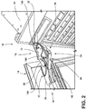
FIG. 2 is a top perspective view of the articulating hinge ofFIG. 1 with an enclosure member removed; -
FIG. 3 is an exploded perspective view of an aspect of the articulating wire chase and the articulating hinge; -
FIG. 4 is a top perspective view of the articulating hinge and a base member of the articulating wire chase, shown in an extended position; -
FIG. 5 is a top perspective view of the articulating hinge ofFIG. 4 and showing an aspect of the flexible conduit positioned within the articulating wire chase and shown in the elongated position; -
FIG. 6 is an enlarged perspective view of the articulating hinge ofFIG. 5 taken at area VI-VI; -
FIG. 7 is a top perspective view of the articulating hinge ofFIG. 5 and showing the enclosure member coupled with the base member; -
FIG. 8 is a top plan view of the articulating hinge in the collapsed position and the articulating wire chase shown in a serpentine position, with the enclosure member removed; -
FIG. 9 is a top plan view of the articulating hinge ofFIG. 8 and showing the articulating hinge and the articulating wire chase moving toward the elongated position; -
FIG. 10 is a top plan view of the articulating hinge ofFIG. 9 and showing the articulating hinge moving toward the extended position; and -
FIG. 11 is a top plan view of the articulating hinge in the extended position and the articulating wire chase in the elongated position. - For purposes of description herein the terms "upper," "lower," "right," "left," "rear," "front," "vertical," "horizontal," and derivatives thereof shall relate to the device as oriented in
FIG. 1 . However, it is to be understood that the device may assume various alternative orientations and step sequences, except where expressly specified to the contrary. It is also to be understood that the specific devices and processes illustrated in the attached drawings, and described in the following specification are simply exemplary embodiments of the inventive concepts defined in the appended claims. Hence, specific dimensions and other physical characteristics relating to the embodiments disclosed herein are not to be considered as limiting, unless the claims expressly state otherwise. - With respect to
FIGS. 1-11 ,reference numeral 10 generally refers to an articulating wire chase that is incorporated within anarticulating hinge 12 for operating adoor panel 14 for anappliance 16 between open and closedpositions position 20 of thedoor panel 14 corresponds to a collapsedposition 22 of thearticulating hinge 12. Additionally, theopen position 18 of thedoor panel 14 typically corresponds to an extendedposition 24 of thearticulating hinge 12. According to various aspects of the device, ahinge assembly 26 for anappliance 16, typically a refrigerating appliance, includes anarticulating hinge 12 positioned at top and bottom portions of thedoor panel 14. The articulatinghinge 12 can include a doorengaging member 28 or bracket that is configured to attach to thedoor panel 14. During operation of thedoor panel 14, the doorengaging member 28 operates through anoperational path 30 for thearticulating hinge 12. Acabinet engaging member 32 or bracket is configured to attach to thestructural cabinet 34. Anarticulating mechanism 36 extends between the doorengaging member 28 and thecabinet engaging member 32. Thearticulating mechanism 36 partially defines theoperational path 30 of the doorengaging member 28. An articulatingwire chase 10 is rotationally coupled to thecabinet engaging member 32 and is slidably coupled to a portion of the articulatingmechanism 36 at aguide slot 38 of the articulatingwire chase 10. The articulatingmechanism 36 is operable between a collapsedposition 22 and an extendedposition 24. Operation of the articulatingmechanism 36 contemporaneously operates the articulatingwire chase 10 between aserpentine position 40 that corresponds to the collapsedposition 22 and anelongated position 42 that corresponds to the extendedposition 24 of thearticulating hinge 12. Through this configuration, thedoor engaging member 28, thecabinet engaging member 32 and thearticulating mechanism 36 define a four-part linkage 44 that operates thedoor panel 14 between the open and closedpositions cabinet engaging member 32 and part of the articulatingmechanism 36 to define a three-part linkage 46 that cooperatively operates with the four-part linkage 44 between the collapsed and extendedpositions - Referring again to
FIGS. 1-11 , thearticulating hinge 12 of thehinge assembly 26 serves to operate thedoor panel 14 between the closedposition 20 and anopen position 18 through theoperational path 30 of the doorengaging member 28. Thearticulating hinge 12 having the articulatingwire chase 10 can be located proximate a top portion of thedoor panel 14 or proximate a bottom portion of thedoor panel 14, or both. Through the operation of thearticulating hinge 12, thedoor panel 14 operates to theopen position 18 in a simultaneous rotational and outward translatingmotion 60 that rotates thedoor panel 14 away from thestructural cabinet 34 and also translates a position of thedoor panel 14 away from thestructural cabinet 34. The use of the articulatinghinge 12 provides for placement of theappliance 16 in a relatively confined space and in a generally flush configuration with surrounding millwork and cabinetry. The use of thearticulating hinge 12 also provides the user with a gliding-type feel and aesthetic for thedoor panel 14 as it moves between the open and closedpositions hinge 12 can also provide for a preciseopen position 18 of thedoor panel 14 where thearticulating hinge 12 stops the outward translatingmotion 60 of thedoor panel 14 at the extendedposition 24 of thearticulating hinge 12. - In using the
articulating hinge 12 in connection with thedoor panel 14, various services including electricity and water can be delivered from thestructural cabinet 34 and into thedoor panel 14. These services are delivered via thearticulating hinge 12 and into various components contained within thedoor panel 14. These components can include, but are not limited to, electrical controls, water dispensers, ice dispensers, user interface mechanisms, connectivity devices, combinations thereof, and other similar devices that may require electrical communication and/or fluid communication between thedoor panel 14 and thestructural cabinet 34. - Referring again to
FIGS. 3-11 , the articulatingwire chase 10 can include ahousing 70 that includes abase member 72 and anenclosure member 74. Thebase member 72 is typically coupled with portions of the articulatinghinge 12 and includes theguide slot 38. Through this connection, the articulating wire chase 10 forms a simultaneous rotating and translatingmotion 60 that cooperates with the translatingmotion 60 of thearticulating hinge 12. Aflexible conduit 76 extends from thestructural cabinet 34 and to thedoor panel 14 and is retained within the articulatingwire chase 10 in each of the serpentine andelongated positions flexible conduit 76 is typically secured within the articulatingwire chase 10 by a plurality of hold-down features 78 that are defined within the articulatingwire chase 10. The plurality of hold-down features 78 that secure theflexible conduit 76 can at least partially define a securingportion 80 of the articulatingwire chase 10. An adjustingportion 82 of theflexible conduit 76 is typically positioned outside of the securingportion 80 and is slidably operable with respect to the articulatingmechanism 36 and the articulatingwire chase 10. Astable portion 84 of theflexible conduit 76 is located within the securingportion 80 of the articulatingwire chase 10. Thestable portion 84 of theflexible conduit 76 is configured to maintain aconsistent position 86 or a substantiallyconsistent position 86 with respect to the articulatingwire chase 10 as the articulatingwire chase 10 operates between theserpentine position 40 and theelongated position 42. Maintaining portions of theflexible conduit 76 in theconsistent position 86 serves to define a substantially repeatable motion of theflexible conduit 76 as it moves with respect to the articulatingwire chase 10 between theserpentine position 40 and theelongated position 42. - As discussed above, the
serpentine position 40 and theelongated position 42 correspond to thecollapsed position 22 and theextended position 24, respectively, of the articulatinghinge 12. Using the substantiallyconsistent position 86 of theflexible conduit 76, and the substantially repeatable motion, pinching, crimping and other undesirable folding of theflexible conduit 76 can be prevented, that might otherwise cause damage to the wiring, tubing, andother service conduits 90 contained within theflexible conduit 76. - Referring again to
FIGS. 3-11 , thehousing 70 for the articulatingwire chase 10 can include the hold-down features 78 that may extend from thebase member 72 of thehousing 70 or from theenclosure member 74 of thehousing 70. Typically, the hold-down features 78 includearcuate retainers 100 that substantially encircle portions of theflexible conduit 76. Theflexible conduit 76 can rest within the arcuate shape of thearcuate retainers 100. Additionally, in certain aspects of the device, theflexible conduit 76 can snap into, or under, portions of thearcuate retainers 100 to be held in place between anupper surface 102 of thebase member 72 and thearcuate retainers 100. - As exemplified in
FIGS. 3-6 , thearcuate retainers 100 include a firstcurved portions 120 that extends upward from theupper surface 102 of thebase member 72 and curves generally perpendicular to form at least a portion of the securingportion 80 of the articulatingwire chase 10. Additionally, thearcuate retainers 100 can also include a secondcurved portion 122 that curves along the shape of the securingportion 80 to formpredetermined bending locations 124 for theflexible conduit 76. Thesepredetermined bending locations 124 are typically used to define thestable portion 84 of theflexible conduit 76 located within the securingportion 80 for the articulatingwire chase 10. Accordingly, as the articulatingwire chase 10 and the articulatinghinge 12 are moved from thecollapsed position 22 to theextended position 24, theflexible conduit 76 can be substantially retained within thearcuate retainers 100 to define thestable portion 84 that remains in the substantiallyconsistent position 86 through the movement of the articulatinghinge 12 and the articulatingwire chase 10. In this manner, the positioning of thestable portion 84 of theflexible conduit 76 in theserpentine position 40 is substantially similar to that of thestable portion 84 for theflexible conduit 76 in theelongated position 42. As discussed above, this configuration of thearcuate retainers 100 for the articulatingwire chase 10 are configured to prevent unwanted crimping, folding, or other damage to theflexible conduit 76 or theservice conduits 90 contained therein. Thearcuate retainers 100 also provide for a limited amount of controlled bending at the secondcurved portion 122 that defines the bendinglocations 124. - In addition to the
arcuate retainers 100, thebase member 72 of thehousing 70 can include anouter wall 130 that at least partially defines acabinet side aperture 132 of thehousing 70. Thiscabinet side aperture 132 can at least partially define the securingportion 80 of thehousing 70. Within thecabinet side aperture 132 of thehousing 70, theflexible conduit 76 is maintained within the substantiallyconsistent position 86 and can form part of thestable portion 84 of theflexible conduit 76 during operation of the articulatingwire chase 10 and the articulatinghinge 12. Theouter wall 130 for thebase member 72 can include acabinet side bumper 134 that forms a portion of thecabinet side aperture 132. Thecabinet side aperture 132 can also be defined by apivot 136 that rotationally engages apost 138 of the articulatinghinge 12. During operation of the articulatingwire chase 10 and the articulatinghinge 12, thehousing 70 of the articulatingwire chase 10 rotationally operates about thepivot 136. Thepost 138 extending upward from the articulatinghinge 12 extends through thepivot 136 and can define a portion of thecabinet side aperture 132 that partially defines the securingportion 80 of thewire chase 10. Accordingly, thecabinet side aperture 132 of thehousing 70 is defined by thecabinet side bumper 134 and thepivot 136 that rotationally engages thepost 138 of the articulatinghinge 12. - Referring again to
FIGS. 3-11 , thehousing 70 also defines adoor side aperture 150 that defines a slidingpath 152 through which theflexible conduit 76 operates to define serpentine andelongated positions flexible conduit 76 that slides within thedoor side aperture 150 is part of the adjustingportion 82 of theflexible conduit 76. Theouter wall 130 of thebase member 72 also includes adoor side bumper 154. Thedoor side bumper 154 defines an outer extent of the slidingpath 152 for the adjustingportion 82 of theflexible conduit 76. In certain embodiments, thedoor side bumper 154 also defines theelongated position 42 of theflexible conduit 76, wherein theflexible conduit 76 is positioned against or near thedoor side bumper 154 in theelongated position 42. Thedoor side bumper 154 of thehousing 70 and a slidingmember 156 that extends upward from the articulatinghinge 12 may cooperate to maintain theflexible conduit 76 in a predetermined position that is indicative of theelongated position 42 of theflexible conduit 76. The slidingmember 156 slidably operates through theguide slot 38 defined within thebase member 72 of thehousing 70 for the articulatingwire chase 10. - In various aspects of the device, operation of the sliding
member 156 through theguide slot 38 from thecollapsed position 22 to theextended position 24 may bias theflexible conduit 76 toward a predetermined state of theelongated position 42 for theflexible conduit 76. As the slidingmember 156 moves through theguide slot 38, the slidingmember 156 may bias theflexible conduit 76 toward thedoor side bumper 154. - In certain aspects of the device, the sliding
member 156 that operates through theguide slot 38 may have a substantially low profile such that as the slidingmember 156 moves through theguide slot 38, the slidingmember 156 may pass under portions of theflexible conduit 76 as the articulatinghinge 12 and the articulatingwire chase 10 operate between thecollapsed position 22 and theextended position 24. - Referring again to
FIGS. 1-11 , various aspects of theappliance 16 can include thestructural cabinet 34 and theoperable door panel 14 that is coupled to thestructural cabinet 34 to define open andclosed positions hinge assembly 26 that includes the articulatinghinge 12 operationally engages thedoor panel 14 to thestructural cabinet 34 to define anoperational path 30 of thedoor panel 14 that includes the open andclosed positions wire chase 10 extends from thestructural cabinet 34 to the operable door. The articulatinghinge 12 includes a four-part linkage 44 and the articulatingwire chase 10 includes a three-part linkage 46 that incorporates a portion of the four-part linkage 44. The articulatinghinge assembly 26 and the articulatingwire chase 10 cooperatively operate between the collapsed andextended positions hinge 12 and the articulatingwire chase 10, theflexible conduit 76 includes astable portion 84 that maintains the consistent or substantiallyconsistent position 86 with respect to the articulatingwire chase 10 and the securingportion 80 of thewire chase 10. Additionally, an adjustingportion 82 of theflexible conduit 76 slidingly operates with respect to the articulatinghinge 12 and the articulatingwire chase 10 in a substantially repeatable fashion as thedoor panel 14 operates between the open andclosed positions - Referring again to
FIGS. 1-11 , the articulatingwire chase 10 includes aguide slot 38 that slidably engages the slidingmember 156 of the articulatinghinge 12. Theguide slot 38 is configured to be a slot defined within thebase member 72 of thehousing 70 that forms the articulatingwire chase 10. Movement of the slidingmember 156 through theguide slot 38 serves to guide arotational operation 170 of thebase member 72 with respect to thepivot 136 that is positioned at the opposite end of thehousing 70. Therotational operation 170 of thebase member 72, in conjunction with the translatingmotion 60 of thedoor engaging member 28 define the translatingmotion 60 of thedoor engaging member 28 define the translatingmotion 60 of the articulatingwire chase 10. - In certain aspects of the device, the translating
motion 60 of the articulatinghinge 12 cooperates with theguide slot 38 of the articulatingwire chase 10 to promote a rotational movement of thehousing 70 about thepivot 136. Through this configuration, thestable portion 84 of theflexible conduit 76 that is positioned at thedoor side aperture 150 at least partially rotates about thepivot 136 as the articulatingwire chase 10 operates between the serpentine andextended positions cabinet side aperture 132 remains relatively close to thestructural cabinet 34 to prevent tugging of theflexible conduit 76 away from thestructural cabinet 34. Conversely, theserpentine position 40 of theflexible conduit 76 within the articulatingwire chase 10 in thecollapsed position 22 provides for an accumulatedslack 180 of theflexible conduit 76 within the articulatingwire chase 10. As the articulatingwire chase 10 operates from theserpentine position 40 toward theelongated position 42, the accumulatedslack 180 of theflexible conduit 76 within the articulatingwire chase 10 is substantially straightened to define theelongated position 42 of theflexible conduit 76 that moves through thestable portion 84 of theflexible conduit 76 and the adjustingportion 82 of theflexible conduit 76. - Referring again to
FIGS. 3-11 , thebase member 72 and theenclosure member 74 that form thehousing 70 can be coupled together viavarious clipping mechanisms 190 that extend between thebase member 72 and theenclosure member 74. Theclipping mechanism 190 of thebase member 72 is positioned so as not to disturb the movement of theflexible conduit 76 between theserpentine position 40 and theelongated position 42. - Referring again to
FIGS. 6-11 , thepivot 136 that engages thepost 138 of the articulatinghinge 12 can include ashield member 196 that extends at least partially around thepost 138. In this manner, theshield member 196 serves to at least partially define thecabinet side aperture 132 of thehousing 70 and also maintains a separation between theflexible conduit 76 and thepivot 136 and thepost 138 during operation of the articulatinghinge 12 between the collapsed andextended positions - Referring again to
FIGS. 3-11 , thebase member 72 of the articulatingwire chase 10 can include at least onearcuate retainer 100 for maintaining thestable portion 84 of theflexible conduit 76 within the substantiallyconsistent position 86. In various aspects, thebase member 72 can include three separatearcuate retainers 100 that are positioned in a generally serpentine or sinusoidal configuration within thehousing 70. During operation of the articulatinghinge 12 between the collapsed andextended positions stable portion 84 of theflexible conduit 76 maintains the substantiallyconsistent position 86 within thehousing 70 as the articulatingwire chase 10 moves between theserpentine position 40 and theelongated position 42. - During this movement of the
flexible conduit 76, the adjustingportion 82 of theflexible conduit 76 slidably operates along thehousing 70 and also along portions of the articulatinghinge 12 as the door moves between theclosed position 20 and theopen position 18. - According to various aspects of the device, the articulating
hinge 12 having the integrated articulatingwire chase 10 can be used invarious appliances 16.Such appliances 16 can include, but are not limited to, refrigerators, freezers, laundry appliances, dishwashers, small appliances, and other similar appliances that require use of an operable panel that may operate between open andclosed positions - In various aspects of the device, the
housing 70 for the articulatingwire chase 10 can be made of various materials. Such materials can include, but are not limited to, plastic, various polymers, composite materials, metals, combinations thereof, and other similar materials. It is also contemplated that thebase member 72 and theenclosure member 74 for thehousing 70 can be made of different materials where various finishes are desired near the articulatinghinge 12.
Claims (15)
- A hinge assembly (26) for a refrigerating appliance (16), the hinge assembly (26) comprising:a door engaging member (28) that is configured to attach to a door panel (14) through an operational path (30) of the door engaging member (28);a cabinet engaging member (32) that is configured to attach to a structural cabinet (34);an articulating mechanism (36) extending between the door engaging member (28) and the cabinet engaging member (32), wherein the articulating mechanism (36) partially defines the operational path (30) of the door engaging member (28);an articulating wire chase (10) that is coupled to the cabinet engaging member (32) and slidably coupled to the articulating mechanism (36) at a guide slot (38), wherein the articulating mechanism (36) is operable between a collapsed position (22) and an extended position (24), and wherein operation of the articulating mechanism (36) operates the articulating wire chase (10) between a serpentine position (40) and an elongated position (42).
- The hinge assembly (26) of claim 1, wherein the door engaging member (28), the cabinet engaging member (32) and the articulating mechanism (36) defines a four-part linkage and the articulating wire chase (10) couples with the cabinet engaging member (32) and part of the articulating mechanism (36) to define a three-part linkage (46) that cooperatively operates with the four-part linkage (44) between the collapsed and extended positions (22, 24).
- The hinge assembly (26) of any one or more of claims 1-2, wherein the articulating wire chase (10) includes a housing (70) having a base member (72) and an enclosure member (74).
- The hinge assembly (26) of claim 3, wherein the housing (70) includes hold-down features (78) that secure a flexible conduit (76) within a securing portion (80) of the articulating wire chase (10).
- The hinge assembly (26) of claim 4, wherein an adjusting portion (82) of the flexible conduit (76) outside of the securing portion (80) is slidably operable with the articulating mechanism (36) and the articulating wire chase (10).
- The hinge assembly (26) of claim 5, wherein a portion of the flexible conduit (76) located within the securing portion (80) maintains a substantially consistent position (86) with respect to the articulating wire chase (10) as the articulating wire chase (10) operates between the serpentine position (40) and the elongated position (42).
- The hinge assembly (26) of any one or more of claims 4-6, wherein the hold-down features (78) include arcuate retainers (100) that substantially encircle portions of the flexible conduit (76).
- The hinge assembly (26) of any one or more of claims 3-7, wherein the door engaging member (28) is configured to attach to the door panel (14) proximate a top portion of the door panel (14).
- The hinge assembly (26) of any one or more of claims 5-8, wherein the housing (70) defines a cabinet side aperture (132) that partially defines the securing portion (80) of the flexible conduit (76).
- The hinge assembly (26) of claim 8, wherein the housing (70) defines a door side aperture (150) that defines a sliding path (152) through which the flexible conduit (76) operates to define the serpentine and elongated positions (40, 42).
- The hinge assembly (26) of claim 9, wherein the base member (72) includes an outer wall (130) having a door side bumper (154) and a cabinet side bumper (134).
- The hinge assembly (26) of claim 11, wherein the cabinet side bumper (134) partially defines the securing portion (80) and the door side bumper (154) defines an outer extent of the sliding path (152) and the elongated position (42).
- The hinge assembly (26) of claim 12, wherein the door side bumper (154) and a sliding member (156) cooperate to maintain the flexible conduit (76) in a predetermined position indicative of the elongated position (42), and wherein the sliding member (156) operates through the guide slot (38).
- The hinge assembly (26) of claim 13, wherein operation of the sliding member (156) through the guide slot (38) from the collapsed position (22) to the extended position (24) biases the flexible conduit (76) toward the predetermined position of the elongated position (42).
- A refrigerating appliance (16) incorporating the hinge assembly (26) of any one or more of claims 1-14, wherein the refrigerating appliance (16) includes a structural cabinet (34) that is coupled with the cabinet engaging member (32) and a door panel (14) that coupled with the door engaging member (28).
Applications Claiming Priority (1)
| Application Number | Priority Date | Filing Date | Title |
|---|---|---|---|
| US16/236,389 US11091943B2 (en) | 2018-12-29 | 2018-12-29 | Articulating wire chase for use with an articulating hinge for an appliance door |
Publications (2)
| Publication Number | Publication Date |
|---|---|
| EP3674504A1 true EP3674504A1 (en) | 2020-07-01 |
| EP3674504B1 EP3674504B1 (en) | 2021-07-28 |
Family
ID=68696251
Family Applications (1)
| Application Number | Title | Priority Date | Filing Date |
|---|---|---|---|
| EP19211361.1A Active EP3674504B1 (en) | 2018-12-29 | 2019-11-25 | Articulating wire chase for use with an articulating hinge for an appliance door |
Country Status (3)
| Country | Link |
|---|---|
| US (1) | US11091943B2 (en) |
| EP (1) | EP3674504B1 (en) |
| CN (1) | CN111379489B (en) |
Cited By (2)
| Publication number | Priority date | Publication date | Assignee | Title |
|---|---|---|---|---|
| EP3957936A1 (en) * | 2020-08-18 | 2022-02-23 | LG Electronics Inc. | Refrigerator |
| AU2021209313B2 (en) * | 2020-07-30 | 2023-08-10 | Eptech Co., Ltd. | Multi-joint link hinge and refrigerator including the same |
Families Citing this family (6)
| Publication number | Priority date | Publication date | Assignee | Title |
|---|---|---|---|---|
| KR102253487B1 (en) * | 2017-01-03 | 2021-05-18 | 삼성전자주식회사 | A built-in refrigerator including a wire cover unit |
| KR102841675B1 (en) * | 2020-05-19 | 2025-08-01 | 엘지전자 주식회사 | Center hinge and refrigerator having this |
| CN113685104B (en) | 2020-05-19 | 2023-03-14 | Lg电子株式会社 | Multi-joint connecting rod hinge and refrigerator comprising same |
| TR2021018742A2 (en) * | 2021-11-30 | 2023-06-21 | Bsh Ev Aletleri Sanayi Ve Ticaret Anonim Sirketi | A COOLING DEVICE WITH A PIPE ARRANGEMENT |
| TR2021020751A1 (en) | 2021-12-23 | 2023-07-21 | Bsh Ev Aletleri Sanayi Ve Ticaret Anonim Sirketi | A COOLING DEVICE HAVING A HUMIDITY CONTROLLED CONTAINER |
| EP4450906A1 (en) * | 2023-04-20 | 2024-10-23 | LG Electronics Inc. | Refrigerator |
Citations (2)
| Publication number | Priority date | Publication date | Assignee | Title |
|---|---|---|---|---|
| US3883201A (en) * | 1972-10-20 | 1975-05-13 | San Giorgio Elettrodomesti | Washing machine on the loading door of which is mounted an electrically operated component |
| DE202007008106U1 (en) * | 2007-06-09 | 2008-10-23 | Liebherr-Hausgeräte Lienz Gmbh | Fridge and / or freezer |
Family Cites Families (17)
| Publication number | Priority date | Publication date | Assignee | Title |
|---|---|---|---|---|
| BR0205050A (en) | 2002-11-25 | 2004-06-29 | Multibras Eletrodomesticos Sa | Refrigerator and freezer door power supply system |
| US7146766B2 (en) * | 2004-03-16 | 2006-12-12 | Manitowoc Foodservice Companies, Inc. | Door control assembly |
| DE102005004957B4 (en) * | 2005-02-02 | 2013-05-08 | Hettich-Oni Gmbh & Co. Kg | Multilink hinge |
| KR101349986B1 (en) | 2007-05-23 | 2014-01-24 | 엘지전자 주식회사 | A lead wire connecting structure for refrigerator |
| CN101086194A (en) * | 2007-07-03 | 2007-12-12 | 海尔集团公司 | All-purpose refrigerator threading hinge |
| KR20090074936A (en) | 2008-01-03 | 2009-07-08 | 주식회사 대우일렉트로닉스 | Refrigerator upper hinge structure |
| KR101469980B1 (en) | 2008-04-02 | 2014-12-05 | 엘지전자 주식회사 | Hinge assembly |
| TR201301119A2 (en) * | 2013-01-30 | 2014-08-21 | Bsh Ev Aletleri San Ve Tic As | A household appliance that includes a transmission element between a body and a door. |
| EP2978916A1 (en) * | 2013-03-26 | 2016-02-03 | Arçelik Anonim Sirketi | Cooling device hinge mechanism and cable installation device |
| JP6092027B2 (en) * | 2013-07-12 | 2017-03-08 | 東芝ライフスタイル株式会社 | refrigerator |
| ITTO20130710A1 (en) * | 2013-09-02 | 2015-03-03 | Indesit Co Spa | REFRIGERATION APPLIANCE WITH PASSAGE FOR FLEXIBLE TUBULAR ELEMENT BETWEEN CABINET AND DOOR |
| EP3155336B1 (en) | 2015-06-11 | 2020-10-21 | LG Electronics Inc. | Refrigerator and control method for refrigerator |
| KR101862564B1 (en) | 2016-01-05 | 2018-05-30 | 엘지전자 주식회사 | Refrigerator |
| DE102016123498A1 (en) * | 2016-12-05 | 2018-06-07 | Hettich-Oni Gmbh & Co. Kg | Multilink hinge |
| US10544983B2 (en) * | 2017-01-03 | 2020-01-28 | Samsung Electronics Co., Ltd. | Refrigerator |
| KR102253487B1 (en) * | 2017-01-03 | 2021-05-18 | 삼성전자주식회사 | A built-in refrigerator including a wire cover unit |
| CN108826814A (en) * | 2018-07-11 | 2018-11-16 | 青岛海尔特种电冰柜有限公司 | A kind of ice-box hinge, refrigerator Wiring structure and refrigerator |
-
2018
- 2018-12-29 US US16/236,389 patent/US11091943B2/en active Active
-
2019
- 2019-11-25 EP EP19211361.1A patent/EP3674504B1/en active Active
- 2019-12-05 CN CN201911233791.1A patent/CN111379489B/en not_active Expired - Fee Related
Patent Citations (2)
| Publication number | Priority date | Publication date | Assignee | Title |
|---|---|---|---|---|
| US3883201A (en) * | 1972-10-20 | 1975-05-13 | San Giorgio Elettrodomesti | Washing machine on the loading door of which is mounted an electrically operated component |
| DE202007008106U1 (en) * | 2007-06-09 | 2008-10-23 | Liebherr-Hausgeräte Lienz Gmbh | Fridge and / or freezer |
Cited By (7)
| Publication number | Priority date | Publication date | Assignee | Title |
|---|---|---|---|---|
| AU2021209313B2 (en) * | 2020-07-30 | 2023-08-10 | Eptech Co., Ltd. | Multi-joint link hinge and refrigerator including the same |
| US12130072B2 (en) | 2020-07-30 | 2024-10-29 | Lg Electronics Inc. | Multi-joint link hinge and refrigerator including the same |
| US12449187B2 (en) | 2020-07-30 | 2025-10-21 | Lg Electronics Inc. | Multi-joint link hinge and refrigerator including the same |
| EP3957936A1 (en) * | 2020-08-18 | 2022-02-23 | LG Electronics Inc. | Refrigerator |
| US11774165B2 (en) | 2020-08-18 | 2023-10-03 | Lg Electronics Inc. | Refrigerator |
| EP4368927A3 (en) * | 2020-08-18 | 2024-06-26 | LG Electronics Inc. | Refrigerator |
| US12181207B2 (en) | 2020-08-18 | 2024-12-31 | Lg Electronics Inc. | Refrigerator |
Also Published As
| Publication number | Publication date |
|---|---|
| US11091943B2 (en) | 2021-08-17 |
| US20200208450A1 (en) | 2020-07-02 |
| EP3674504B1 (en) | 2021-07-28 |
| CN111379489A (en) | 2020-07-07 |
| CN111379489B (en) | 2023-03-24 |
Similar Documents
| Publication | Publication Date | Title |
|---|---|---|
| EP3674504B1 (en) | Articulating wire chase for use with an articulating hinge for an appliance door | |
| US5263509A (en) | Refrigerator with door mounted dispenser supply mechanism | |
| US9297572B2 (en) | Appliance with an articulating handle | |
| CN103069234B (en) | There is the refrigerator shelf regulating system that frame throws light on | |
| EP3042137B1 (en) | A refrigerating appliance with a passage for flexible tubular element between cabinet and door | |
| US20090179539A1 (en) | Refrigerator door stop | |
| CN113272609B (en) | Linear hinge for appliances | |
| EP3332670B1 (en) | Adjustable slide rail mechanism for drawers | |
| EP2881029B1 (en) | Built-in domestic appliance with decorative panel applied to the door | |
| EP1821052A2 (en) | Refrigerator having a door with integrated control panel | |
| US20060049730A1 (en) | Drawer frame | |
| KR102445184B1 (en) | refrigerator | |
| AU2019235965B2 (en) | Refrigerator | |
| KR100465121B1 (en) | article storage apparatus | |
| CN106705546A (en) | Refrigerator | |
| RU2440542C2 (en) | Domestic appliance casing | |
| USRE43013E1 (en) | Cigarette holding and dispensing apparatus | |
| US20210000256A1 (en) | Piece of furniture or domestic appliance and method for mounting a functional unit of a drawer element in a piece of furniture or domestic appliance | |
| US10234020B2 (en) | Shutter member for a motor vehicle control lever, and tunnel console provided with such shutter member | |
| ES2215979T3 (en) | ELECTRICAL APPLIANCE INCORPORATED WITH DECORATIVE PANEL APPLIED TO THE DOOR. | |
| EP0744521A1 (en) | Hinge with movable axis of rotation in particular for the panel-finished doors of built-in dish washing machines | |
| CN113329667A (en) | Drawer | |
| US12578138B2 (en) | Refrigerator | |
| KR102920016B1 (en) | A refrigerator | |
| KR102065741B1 (en) | Dishwasher |
Legal Events
| Date | Code | Title | Description |
|---|---|---|---|
| PUAI | Public reference made under article 153(3) epc to a published international application that has entered the european phase |
Free format text: ORIGINAL CODE: 0009012 |
|
| STAA | Information on the status of an ep patent application or granted ep patent |
Free format text: STATUS: THE APPLICATION HAS BEEN PUBLISHED |
|
| AK | Designated contracting states |
Kind code of ref document: A1 Designated state(s): AL AT BE BG CH CY CZ DE DK EE ES FI FR GB GR HR HU IE IS IT LI LT LU LV MC MK MT NL NO PL PT RO RS SE SI SK SM TR |
|
| AX | Request for extension of the european patent |
Extension state: BA ME |
|
| STAA | Information on the status of an ep patent application or granted ep patent |
Free format text: STATUS: REQUEST FOR EXAMINATION WAS MADE |
|
| 17P | Request for examination filed |
Effective date: 20201215 |
|
| RBV | Designated contracting states (corrected) |
Designated state(s): AL AT BE BG CH CY CZ DE DK EE ES FI FR GB GR HR HU IE IS IT LI LT LU LV MC MK MT NL NO PL PT RO RS SE SI SK SM TR |
|
| GRAP | Despatch of communication of intention to grant a patent |
Free format text: ORIGINAL CODE: EPIDOSNIGR1 |
|
| STAA | Information on the status of an ep patent application or granted ep patent |
Free format text: STATUS: GRANT OF PATENT IS INTENDED |
|
| RIC1 | Information provided on ipc code assigned before grant |
Ipc: E05D 3/16 20060101AFI20210412BHEP Ipc: E05D 11/00 20060101ALI20210412BHEP Ipc: F25D 23/02 20060101ALI20210412BHEP |
|
| INTG | Intention to grant announced |
Effective date: 20210429 |
|
| GRAS | Grant fee paid |
Free format text: ORIGINAL CODE: EPIDOSNIGR3 |
|
| GRAA | (expected) grant |
Free format text: ORIGINAL CODE: 0009210 |
|
| STAA | Information on the status of an ep patent application or granted ep patent |
Free format text: STATUS: THE PATENT HAS BEEN GRANTED |
|
| AK | Designated contracting states |
Kind code of ref document: B1 Designated state(s): AL AT BE BG CH CY CZ DE DK EE ES FI FR GB GR HR HU IE IS IT LI LT LU LV MC MK MT NL NO PL PT RO RS SE SI SK SM TR |
|
| REG | Reference to a national code |
Ref country code: GB Ref legal event code: FG4D |
|
| REG | Reference to a national code |
Ref country code: CH Ref legal event code: EP |
|
| REG | Reference to a national code |
Ref country code: AT Ref legal event code: REF Ref document number: 1414878 Country of ref document: AT Kind code of ref document: T Effective date: 20210815 |
|
| REG | Reference to a national code |
Ref country code: IE Ref legal event code: FG4D |
|
| REG | Reference to a national code |
Ref country code: DE Ref legal event code: R096 Ref document number: 602019006433 Country of ref document: DE |
|
| REG | Reference to a national code |
Ref country code: LT Ref legal event code: MG9D |
|
| REG | Reference to a national code |
Ref country code: NL Ref legal event code: MP Effective date: 20210728 |
|
| REG | Reference to a national code |
Ref country code: AT Ref legal event code: MK05 Ref document number: 1414878 Country of ref document: AT Kind code of ref document: T Effective date: 20210728 |
|
| PG25 | Lapsed in a contracting state [announced via postgrant information from national office to epo] |
Ref country code: RS Free format text: LAPSE BECAUSE OF FAILURE TO SUBMIT A TRANSLATION OF THE DESCRIPTION OR TO PAY THE FEE WITHIN THE PRESCRIBED TIME-LIMIT Effective date: 20210728 Ref country code: SE Free format text: LAPSE BECAUSE OF FAILURE TO SUBMIT A TRANSLATION OF THE DESCRIPTION OR TO PAY THE FEE WITHIN THE PRESCRIBED TIME-LIMIT Effective date: 20210728 Ref country code: ES Free format text: LAPSE BECAUSE OF FAILURE TO SUBMIT A TRANSLATION OF THE DESCRIPTION OR TO PAY THE FEE WITHIN THE PRESCRIBED TIME-LIMIT Effective date: 20210728 Ref country code: NL Free format text: LAPSE BECAUSE OF FAILURE TO SUBMIT A TRANSLATION OF THE DESCRIPTION OR TO PAY THE FEE WITHIN THE PRESCRIBED TIME-LIMIT Effective date: 20210728 Ref country code: PT Free format text: LAPSE BECAUSE OF FAILURE TO SUBMIT A TRANSLATION OF THE DESCRIPTION OR TO PAY THE FEE WITHIN THE PRESCRIBED TIME-LIMIT Effective date: 20211129 Ref country code: NO Free format text: LAPSE BECAUSE OF FAILURE TO SUBMIT A TRANSLATION OF THE DESCRIPTION OR TO PAY THE FEE WITHIN THE PRESCRIBED TIME-LIMIT Effective date: 20211028 Ref country code: HR Free format text: LAPSE BECAUSE OF FAILURE TO SUBMIT A TRANSLATION OF THE DESCRIPTION OR TO PAY THE FEE WITHIN THE PRESCRIBED TIME-LIMIT Effective date: 20210728 Ref country code: FI Free format text: LAPSE BECAUSE OF FAILURE TO SUBMIT A TRANSLATION OF THE DESCRIPTION OR TO PAY THE FEE WITHIN THE PRESCRIBED TIME-LIMIT Effective date: 20210728 Ref country code: AT Free format text: LAPSE BECAUSE OF FAILURE TO SUBMIT A TRANSLATION OF THE DESCRIPTION OR TO PAY THE FEE WITHIN THE PRESCRIBED TIME-LIMIT Effective date: 20210728 Ref country code: BG Free format text: LAPSE BECAUSE OF FAILURE TO SUBMIT A TRANSLATION OF THE DESCRIPTION OR TO PAY THE FEE WITHIN THE PRESCRIBED TIME-LIMIT Effective date: 20211028 Ref country code: LT Free format text: LAPSE BECAUSE OF FAILURE TO SUBMIT A TRANSLATION OF THE DESCRIPTION OR TO PAY THE FEE WITHIN THE PRESCRIBED TIME-LIMIT Effective date: 20210728 |
|
| PG25 | Lapsed in a contracting state [announced via postgrant information from national office to epo] |
Ref country code: PL Free format text: LAPSE BECAUSE OF FAILURE TO SUBMIT A TRANSLATION OF THE DESCRIPTION OR TO PAY THE FEE WITHIN THE PRESCRIBED TIME-LIMIT Effective date: 20210728 Ref country code: LV Free format text: LAPSE BECAUSE OF FAILURE TO SUBMIT A TRANSLATION OF THE DESCRIPTION OR TO PAY THE FEE WITHIN THE PRESCRIBED TIME-LIMIT Effective date: 20210728 Ref country code: GR Free format text: LAPSE BECAUSE OF FAILURE TO SUBMIT A TRANSLATION OF THE DESCRIPTION OR TO PAY THE FEE WITHIN THE PRESCRIBED TIME-LIMIT Effective date: 20211029 |
|
| PG25 | Lapsed in a contracting state [announced via postgrant information from national office to epo] |
Ref country code: DK Free format text: LAPSE BECAUSE OF FAILURE TO SUBMIT A TRANSLATION OF THE DESCRIPTION OR TO PAY THE FEE WITHIN THE PRESCRIBED TIME-LIMIT Effective date: 20210728 |
|
| REG | Reference to a national code |
Ref country code: DE Ref legal event code: R097 Ref document number: 602019006433 Country of ref document: DE |
|
| PG25 | Lapsed in a contracting state [announced via postgrant information from national office to epo] |
Ref country code: SM Free format text: LAPSE BECAUSE OF FAILURE TO SUBMIT A TRANSLATION OF THE DESCRIPTION OR TO PAY THE FEE WITHIN THE PRESCRIBED TIME-LIMIT Effective date: 20210728 Ref country code: SK Free format text: LAPSE BECAUSE OF FAILURE TO SUBMIT A TRANSLATION OF THE DESCRIPTION OR TO PAY THE FEE WITHIN THE PRESCRIBED TIME-LIMIT Effective date: 20210728 Ref country code: RO Free format text: LAPSE BECAUSE OF FAILURE TO SUBMIT A TRANSLATION OF THE DESCRIPTION OR TO PAY THE FEE WITHIN THE PRESCRIBED TIME-LIMIT Effective date: 20210728 Ref country code: EE Free format text: LAPSE BECAUSE OF FAILURE TO SUBMIT A TRANSLATION OF THE DESCRIPTION OR TO PAY THE FEE WITHIN THE PRESCRIBED TIME-LIMIT Effective date: 20210728 Ref country code: CZ Free format text: LAPSE BECAUSE OF FAILURE TO SUBMIT A TRANSLATION OF THE DESCRIPTION OR TO PAY THE FEE WITHIN THE PRESCRIBED TIME-LIMIT Effective date: 20210728 Ref country code: AL Free format text: LAPSE BECAUSE OF FAILURE TO SUBMIT A TRANSLATION OF THE DESCRIPTION OR TO PAY THE FEE WITHIN THE PRESCRIBED TIME-LIMIT Effective date: 20210728 |
|
| PLBE | No opposition filed within time limit |
Free format text: ORIGINAL CODE: 0009261 |
|
| STAA | Information on the status of an ep patent application or granted ep patent |
Free format text: STATUS: NO OPPOSITION FILED WITHIN TIME LIMIT |
|
| PG25 | Lapsed in a contracting state [announced via postgrant information from national office to epo] |
Ref country code: MC Free format text: LAPSE BECAUSE OF FAILURE TO SUBMIT A TRANSLATION OF THE DESCRIPTION OR TO PAY THE FEE WITHIN THE PRESCRIBED TIME-LIMIT Effective date: 20210728 |
|
| 26N | No opposition filed |
Effective date: 20220429 |
|
| PG25 | Lapsed in a contracting state [announced via postgrant information from national office to epo] |
Ref country code: LU Free format text: LAPSE BECAUSE OF NON-PAYMENT OF DUE FEES Effective date: 20211125 Ref country code: BE Free format text: LAPSE BECAUSE OF NON-PAYMENT OF DUE FEES Effective date: 20211130 |
|
| REG | Reference to a national code |
Ref country code: BE Ref legal event code: MM Effective date: 20211130 |
|
| PG25 | Lapsed in a contracting state [announced via postgrant information from national office to epo] |
Ref country code: IE Free format text: LAPSE BECAUSE OF NON-PAYMENT OF DUE FEES Effective date: 20211125 |
|
| P01 | Opt-out of the competence of the unified patent court (upc) registered |
Effective date: 20230522 |
|
| PG25 | Lapsed in a contracting state [announced via postgrant information from national office to epo] |
Ref country code: CY Free format text: LAPSE BECAUSE OF FAILURE TO SUBMIT A TRANSLATION OF THE DESCRIPTION OR TO PAY THE FEE WITHIN THE PRESCRIBED TIME-LIMIT Effective date: 20210728 |
|
| REG | Reference to a national code |
Ref country code: CH Ref legal event code: PL |
|
| PG25 | Lapsed in a contracting state [announced via postgrant information from national office to epo] |
Ref country code: LI Free format text: LAPSE BECAUSE OF NON-PAYMENT OF DUE FEES Effective date: 20221130 Ref country code: HU Free format text: LAPSE BECAUSE OF FAILURE TO SUBMIT A TRANSLATION OF THE DESCRIPTION OR TO PAY THE FEE WITHIN THE PRESCRIBED TIME-LIMIT; INVALID AB INITIO Effective date: 20191125 Ref country code: CH Free format text: LAPSE BECAUSE OF NON-PAYMENT OF DUE FEES Effective date: 20221130 |
|
| PG25 | Lapsed in a contracting state [announced via postgrant information from national office to epo] |
Ref country code: MK Free format text: LAPSE BECAUSE OF FAILURE TO SUBMIT A TRANSLATION OF THE DESCRIPTION OR TO PAY THE FEE WITHIN THE PRESCRIBED TIME-LIMIT Effective date: 20210728 |
|
| PG25 | Lapsed in a contracting state [announced via postgrant information from national office to epo] |
Ref country code: TR Free format text: LAPSE BECAUSE OF FAILURE TO SUBMIT A TRANSLATION OF THE DESCRIPTION OR TO PAY THE FEE WITHIN THE PRESCRIBED TIME-LIMIT Effective date: 20210728 |
|
| PG25 | Lapsed in a contracting state [announced via postgrant information from national office to epo] |
Ref country code: MT Free format text: LAPSE BECAUSE OF FAILURE TO SUBMIT A TRANSLATION OF THE DESCRIPTION OR TO PAY THE FEE WITHIN THE PRESCRIBED TIME-LIMIT Effective date: 20210728 |
|
| PGFP | Annual fee paid to national office [announced via postgrant information from national office to epo] |
Ref country code: DE Payment date: 20251126 Year of fee payment: 7 |
|
| PGFP | Annual fee paid to national office [announced via postgrant information from national office to epo] |
Ref country code: GB Payment date: 20251125 Year of fee payment: 7 |
|
| PGFP | Annual fee paid to national office [announced via postgrant information from national office to epo] |
Ref country code: IT Payment date: 20251107 Year of fee payment: 7 |
|
| PGFP | Annual fee paid to national office [announced via postgrant information from national office to epo] |
Ref country code: FR Payment date: 20251124 Year of fee payment: 7 |