EP3674464A1 - Liquid discharge device, and liquid discharge apparatus and dyeing apparatus including same - Google Patents
Liquid discharge device, and liquid discharge apparatus and dyeing apparatus including same Download PDFInfo
- Publication number
- EP3674464A1 EP3674464A1 EP19215062.1A EP19215062A EP3674464A1 EP 3674464 A1 EP3674464 A1 EP 3674464A1 EP 19215062 A EP19215062 A EP 19215062A EP 3674464 A1 EP3674464 A1 EP 3674464A1
- Authority
- EP
- European Patent Office
- Prior art keywords
- liquid
- head
- discharge
- receptacle
- opening
- Prior art date
- Legal status (The legal status is an assumption and is not a legal conclusion. Google has not performed a legal analysis and makes no representation as to the accuracy of the status listed.)
- Granted
Links
Images




Classifications
-
- D—TEXTILES; PAPER
- D05—SEWING; EMBROIDERING; TUFTING
- D05C—EMBROIDERING; TUFTING
- D05C13/00—Auxiliary devices incorporated in embroidering machines, not otherwise provided for; Ancillary apparatus for use with embroidering machines
-
- D—TEXTILES; PAPER
- D06—TREATMENT OF TEXTILES OR THE LIKE; LAUNDERING; FLEXIBLE MATERIALS NOT OTHERWISE PROVIDED FOR
- D06B—TREATING TEXTILE MATERIALS USING LIQUIDS, GASES OR VAPOURS
- D06B11/00—Treatment of selected parts of textile materials, e.g. partial dyeing
- D06B11/002—Treatment of selected parts of textile materials, e.g. partial dyeing of moving yarns
- D06B11/0023—Treatment of selected parts of textile materials, e.g. partial dyeing of moving yarns by spraying or pouring
-
- B—PERFORMING OPERATIONS; TRANSPORTING
- B41—PRINTING; LINING MACHINES; TYPEWRITERS; STAMPS
- B41J—TYPEWRITERS; SELECTIVE PRINTING MECHANISMS, i.e. MECHANISMS PRINTING OTHERWISE THAN FROM A FORME; CORRECTION OF TYPOGRAPHICAL ERRORS
- B41J11/00—Devices or arrangements of selective printing mechanisms, e.g. ink-jet printers or thermal printers, for supporting or handling copy material in sheet or web form
- B41J11/0015—Devices or arrangements of selective printing mechanisms, e.g. ink-jet printers or thermal printers, for supporting or handling copy material in sheet or web form for treating before, during or after printing or for uniform coating or laminating the copy material before or after printing
- B41J11/002—Curing or drying the ink on the copy materials, e.g. by heating or irradiating
- B41J11/0021—Curing or drying the ink on the copy materials, e.g. by heating or irradiating using irradiation
- B41J11/00216—Curing or drying the ink on the copy materials, e.g. by heating or irradiating using irradiation using infrared [IR] radiation or microwaves
-
- B—PERFORMING OPERATIONS; TRANSPORTING
- B41—PRINTING; LINING MACHINES; TYPEWRITERS; STAMPS
- B41J—TYPEWRITERS; SELECTIVE PRINTING MECHANISMS, i.e. MECHANISMS PRINTING OTHERWISE THAN FROM A FORME; CORRECTION OF TYPOGRAPHICAL ERRORS
- B41J2/00—Typewriters or selective printing mechanisms characterised by the printing or marking process for which they are designed
- B41J2/005—Typewriters or selective printing mechanisms characterised by the printing or marking process for which they are designed characterised by bringing liquid or particles selectively into contact with a printing material
- B41J2/01—Ink jet
- B41J2/135—Nozzles
- B41J2/145—Arrangement thereof
-
- B—PERFORMING OPERATIONS; TRANSPORTING
- B41—PRINTING; LINING MACHINES; TYPEWRITERS; STAMPS
- B41J—TYPEWRITERS; SELECTIVE PRINTING MECHANISMS, i.e. MECHANISMS PRINTING OTHERWISE THAN FROM A FORME; CORRECTION OF TYPOGRAPHICAL ERRORS
- B41J2/00—Typewriters or selective printing mechanisms characterised by the printing or marking process for which they are designed
- B41J2/005—Typewriters or selective printing mechanisms characterised by the printing or marking process for which they are designed characterised by bringing liquid or particles selectively into contact with a printing material
- B41J2/01—Ink jet
- B41J2/135—Nozzles
- B41J2/165—Prevention or detection of nozzle clogging, e.g. cleaning, capping or moistening for nozzles
- B41J2/16505—Caps, spittoons or covers for cleaning or preventing drying out
- B41J2/16508—Caps, spittoons or covers for cleaning or preventing drying out connected with the printer frame
- B41J2/16511—Constructions for cap positioning
- B41J2/16514—Constructions for cap positioning creating a distance between cap and printhead, e.g. for suction or pressurising
-
- B—PERFORMING OPERATIONS; TRANSPORTING
- B41—PRINTING; LINING MACHINES; TYPEWRITERS; STAMPS
- B41J—TYPEWRITERS; SELECTIVE PRINTING MECHANISMS, i.e. MECHANISMS PRINTING OTHERWISE THAN FROM A FORME; CORRECTION OF TYPOGRAPHICAL ERRORS
- B41J2/00—Typewriters or selective printing mechanisms characterised by the printing or marking process for which they are designed
- B41J2/005—Typewriters or selective printing mechanisms characterised by the printing or marking process for which they are designed characterised by bringing liquid or particles selectively into contact with a printing material
- B41J2/01—Ink jet
- B41J2/135—Nozzles
- B41J2/165—Prevention or detection of nozzle clogging, e.g. cleaning, capping or moistening for nozzles
- B41J2/16517—Cleaning of print head nozzles
- B41J2/1652—Cleaning of print head nozzles by driving a fluid through the nozzles to the outside thereof, e.g. by applying pressure to the inside or vacuum at the outside of the print head
- B41J2/16523—Waste ink transport from caps or spittoons, e.g. by suction
-
- B—PERFORMING OPERATIONS; TRANSPORTING
- B41—PRINTING; LINING MACHINES; TYPEWRITERS; STAMPS
- B41J—TYPEWRITERS; SELECTIVE PRINTING MECHANISMS, i.e. MECHANISMS PRINTING OTHERWISE THAN FROM A FORME; CORRECTION OF TYPOGRAPHICAL ERRORS
- B41J2/00—Typewriters or selective printing mechanisms characterised by the printing or marking process for which they are designed
- B41J2/005—Typewriters or selective printing mechanisms characterised by the printing or marking process for which they are designed characterised by bringing liquid or particles selectively into contact with a printing material
- B41J2/01—Ink jet
- B41J2/135—Nozzles
- B41J2/165—Prevention or detection of nozzle clogging, e.g. cleaning, capping or moistening for nozzles
- B41J2/16517—Cleaning of print head nozzles
- B41J2/1652—Cleaning of print head nozzles by driving a fluid through the nozzles to the outside thereof, e.g. by applying pressure to the inside or vacuum at the outside of the print head
- B41J2/16526—Cleaning of print head nozzles by driving a fluid through the nozzles to the outside thereof, e.g. by applying pressure to the inside or vacuum at the outside of the print head by applying pressure only
-
- B—PERFORMING OPERATIONS; TRANSPORTING
- B41—PRINTING; LINING MACHINES; TYPEWRITERS; STAMPS
- B41J—TYPEWRITERS; SELECTIVE PRINTING MECHANISMS, i.e. MECHANISMS PRINTING OTHERWISE THAN FROM A FORME; CORRECTION OF TYPOGRAPHICAL ERRORS
- B41J3/00—Typewriters or selective printing or marking mechanisms characterised by the purpose for which they are constructed
- B41J3/407—Typewriters or selective printing or marking mechanisms characterised by the purpose for which they are constructed for marking on special material
- B41J3/4078—Printing on textile
-
- D—TEXTILES; PAPER
- D05—SEWING; EMBROIDERING; TUFTING
- D05C—EMBROIDERING; TUFTING
- D05C11/00—Devices for guiding, feeding, handling, or treating the threads in embroidering machines; Machine needles; Operating or control mechanisms therefor
- D05C11/24—Devices for guiding, feeding, handling, or treating the threads in embroidering machines; Machine needles; Operating or control mechanisms therefor incorporating devices for dyeing or impregnating the threads
-
- D—TEXTILES; PAPER
- D06—TREATMENT OF TEXTILES OR THE LIKE; LAUNDERING; FLEXIBLE MATERIALS NOT OTHERWISE PROVIDED FOR
- D06P—DYEING OR PRINTING TEXTILES; DYEING LEATHER, FURS OR SOLID MACROMOLECULAR SUBSTANCES IN ANY FORM
- D06P5/00—Other features in dyeing or printing textiles, or dyeing leather, furs, or solid macromolecular substances in any form
- D06P5/30—Ink jet printing
-
- B—PERFORMING OPERATIONS; TRANSPORTING
- B41—PRINTING; LINING MACHINES; TYPEWRITERS; STAMPS
- B41J—TYPEWRITERS; SELECTIVE PRINTING MECHANISMS, i.e. MECHANISMS PRINTING OTHERWISE THAN FROM A FORME; CORRECTION OF TYPOGRAPHICAL ERRORS
- B41J11/00—Devices or arrangements of selective printing mechanisms, e.g. ink-jet printers or thermal printers, for supporting or handling copy material in sheet or web form
- B41J11/0015—Devices or arrangements of selective printing mechanisms, e.g. ink-jet printers or thermal printers, for supporting or handling copy material in sheet or web form for treating before, during or after printing or for uniform coating or laminating the copy material before or after printing
-
- B—PERFORMING OPERATIONS; TRANSPORTING
- B41—PRINTING; LINING MACHINES; TYPEWRITERS; STAMPS
- B41J—TYPEWRITERS; SELECTIVE PRINTING MECHANISMS, i.e. MECHANISMS PRINTING OTHERWISE THAN FROM A FORME; CORRECTION OF TYPOGRAPHICAL ERRORS
- B41J11/00—Devices or arrangements of selective printing mechanisms, e.g. ink-jet printers or thermal printers, for supporting or handling copy material in sheet or web form
- B41J11/0015—Devices or arrangements of selective printing mechanisms, e.g. ink-jet printers or thermal printers, for supporting or handling copy material in sheet or web form for treating before, during or after printing or for uniform coating or laminating the copy material before or after printing
- B41J11/002—Curing or drying the ink on the copy materials, e.g. by heating or irradiating
-
- B—PERFORMING OPERATIONS; TRANSPORTING
- B41—PRINTING; LINING MACHINES; TYPEWRITERS; STAMPS
- B41J—TYPEWRITERS; SELECTIVE PRINTING MECHANISMS, i.e. MECHANISMS PRINTING OTHERWISE THAN FROM A FORME; CORRECTION OF TYPOGRAPHICAL ERRORS
- B41J2/00—Typewriters or selective printing mechanisms characterised by the printing or marking process for which they are designed
- B41J2/005—Typewriters or selective printing mechanisms characterised by the printing or marking process for which they are designed characterised by bringing liquid or particles selectively into contact with a printing material
- B41J2/01—Ink jet
- B41J2/135—Nozzles
- B41J2/165—Prevention or detection of nozzle clogging, e.g. cleaning, capping or moistening for nozzles
- B41J2/16505—Caps, spittoons or covers for cleaning or preventing drying out
- B41J2/16508—Caps, spittoons or covers for cleaning or preventing drying out connected with the printer frame
-
- B—PERFORMING OPERATIONS; TRANSPORTING
- B41—PRINTING; LINING MACHINES; TYPEWRITERS; STAMPS
- B41J—TYPEWRITERS; SELECTIVE PRINTING MECHANISMS, i.e. MECHANISMS PRINTING OTHERWISE THAN FROM A FORME; CORRECTION OF TYPOGRAPHICAL ERRORS
- B41J2/00—Typewriters or selective printing mechanisms characterised by the printing or marking process for which they are designed
- B41J2/005—Typewriters or selective printing mechanisms characterised by the printing or marking process for which they are designed characterised by bringing liquid or particles selectively into contact with a printing material
- B41J2/01—Ink jet
- B41J2/135—Nozzles
- B41J2/165—Prevention or detection of nozzle clogging, e.g. cleaning, capping or moistening for nozzles
- B41J2/16517—Cleaning of print head nozzles
- B41J2/16535—Cleaning of print head nozzles using wiping constructions
- B41J2/16538—Cleaning of print head nozzles using wiping constructions with brushes or wiper blades perpendicular to the nozzle plate
-
- B—PERFORMING OPERATIONS; TRANSPORTING
- B41—PRINTING; LINING MACHINES; TYPEWRITERS; STAMPS
- B41J—TYPEWRITERS; SELECTIVE PRINTING MECHANISMS, i.e. MECHANISMS PRINTING OTHERWISE THAN FROM A FORME; CORRECTION OF TYPOGRAPHICAL ERRORS
- B41J2/00—Typewriters or selective printing mechanisms characterised by the printing or marking process for which they are designed
- B41J2/005—Typewriters or selective printing mechanisms characterised by the printing or marking process for which they are designed characterised by bringing liquid or particles selectively into contact with a printing material
- B41J2/01—Ink jet
- B41J2/135—Nozzles
- B41J2/165—Prevention or detection of nozzle clogging, e.g. cleaning, capping or moistening for nozzles
- B41J2/16517—Cleaning of print head nozzles
- B41J2/16535—Cleaning of print head nozzles using wiping constructions
- B41J2/16544—Constructions for the positioning of wipers
- B41J2/16547—Constructions for the positioning of wipers the wipers and caps or spittoons being on the same movable support
-
- D—TEXTILES; PAPER
- D05—SEWING; EMBROIDERING; TUFTING
- D05D—INDEXING SCHEME ASSOCIATED WITH SUBCLASSES D05B AND D05C, RELATING TO SEWING, EMBROIDERING AND TUFTING
- D05D2305/00—Operations on the work before or after sewing
- D05D2305/22—Physico-chemical treatments
Definitions
- the present disclosure relates to a liquid discharge device, and a liquid discharge apparatus and a dyeing apparatus including the liquid discharge device.
- Apparatuses including a liquid discharge head discharge liquid that does not contribute to liquid application to a target, for maintenance and recovery of the liquid discharge head.
- the liquid not contributing to liquid application is discharged toward, for example, a liquid receptacle.
- Such an operation is called dummy discharge (also called flushing or purging).
- JP-2007-152885-A discloses an apparatus that includes a movable ink receptacle to receive liquid that lands off a recording sheet, for example, when performing full bleed printing.
- the ink receptacle is disposed with a long side thereof aligned in the direction of conveyance of the recording sheet and movable in a short-side direction of the ink receptacle.
- liquid application target the target of liquid application
- an object of the present disclosure is to enable an efficient dummy discharge operation.
- the liquid discharge device includes a head including a nozzle plate having a plurality of nozzles lined in a row and configured to discharge a liquid, and a liquid receptacle configured to receive the liquid discharged from the head.
- the liquid receptacle has an opening through which the liquid discharged from the head passes.
- a longitudinal direction of the opening is along a movement direction of a liquid application target to which the head applies the liquid.
- a width of the opening is greater than a width of the liquid application target.
- a liquid discharge apparatus includes the liquid discharge device and a conveyor defining a conveyance passage of the liquid application target.
- the conveyor is configured to convey the liquid application target.
- the dummy discharge operation can be performed efficiently.
- FIG. 1 is a schematic view of the liquid discharge apparatus.
- FIG. 2 is a view of a liquid application unit of the liquid discharge apparatus.
- FIG. 3 is a view of a row of heads of the liquid application unit as viewed from below.
- a liquid discharge apparatus 100 in FIG. 1 is an in-line embroidery machine.
- the liquid discharge apparatus 100 includes a supply reel 102 on which a thread 101 (a liquid application target) is wound, a liquid application unit 103 (a liquid application device), a fixing unit 104, a post-treatment unit 105, and an embroidery head 106.
- the thread 101 drawn from the supply reel 102 is guided by rollers 108 and 109 as conveyors and continuously stretched to the embroidery head 106.
- the liquid application unit 103 (the liquid discharge device) includes a plurality of heads 1 (1a to 1d) and a plurality of individual maintenance units 2 (2a to 2d) serving as maintenance devices.
- the liquid application unit 103 discharges a liquid of a required color onto the thread 101 which is drawn out from the supply reel 102.
- the individual maintenance units 2 perform maintenance of the heads 1, respectively.
- the heads 1a to 1d discharge, for example, cyan (C), magenta (M), yellow (Y), and black (K) color liquids.
- each of the heads 1 (1a to 1d) includes a nozzle plate 12 in which a plurality of nozzles 11 to discharge a liquid is formed. Specifically, on a face (hereinafter "nozzle face") of the nozzle plate 12, the plurality of nozzles 11 is lined in a row (a nozzle row 10). Each head 1 is disposed such that the direction (a nozzle row direction in which the nozzles 11 are lined) matches the direction of conveyance (movement direction) of the thread 101.
- the individual maintenance units 2 respectively include liquid receptacles 21 (21a to 21d, illustrated in FIG. 2 ) disposed opposite the heads 1 with the thread 101 (the liquid application target) interposed therebetween.
- the fixing unit 104 performs a fixing process (drying process) of the thread 101 to which the liquid is applied from the liquid application unit 103.
- the fixing unit 104 includes, for example, a heater such as an infrared irradiation device and a hot air sprayer, and heats the thread 101 to dry.
- the post-treatment unit 105 includes, for example, a cleaning device that cleans the thread 101, a tension adjustment device that adjusts the tension of the thread 101, a feed amount detector that detects the amount of movement of the thread 101, and a lubricant application device that lubricates the surface of the thread 101.
- the embroidery head 106 embroiders a pattern, for example, on a cloth with the thread 101.
- liquid discharge apparatus in the present embodiment is an embroidery machine
- the present disclosure is not limited thereto. Aspects of the present disclosure are applicable to devices, such as weaving machines and sewing machines, that use linear objects such as threads. Further, aspects of the present disclosure can be applied not only to apparatuses having a post-process, such as an embroidery machine, but also to dyeing apparatuses and the like that dye and wind threads, etc. as described later.
- “thread” includes glass fiber thread, wool thread, cotton thread, synthetic thread, metal thread, wool, cotton, polymer, mixed metal thread, yarn, filament, and linear objects (continuous base materials) to which liquid is applicable.
- the “thread” also includes braids and flat cords (flat braids).
- FIG. 4 is a plan view illustrating a liquid receptacle according to the present embodiment.
- FIG. 5 is a cross-sectional view illustrating the liquid receptacle along a short-side direction thereof.
- the liquid receptacle 21 is a box-shaped container having an opening 22 through which a liquid (droplet) 300 discharged from the head 1 passes.
- the longitudinal direction of the opening 22 of the liquid receptacle 21 is along the movement direction (conveyance direction) of the thread 101 to which the liquid discharged from the head 1 is applied.
- the "direction along the movement direction” is not limited to directions parallel to the movement direction but includes, for example, the direction illustrated in FIG. 11A .
- a width W (a short-side length) of the opening 22 is greater than a width W0 of the thread 101 (liquid application target) in the direction orthogonal to the movement direction, that is, the conveyance direction thereof (W>W0).
- a length L (a long-side length) of the opening 22 is longer than the length of the nozzle row 10 of the head 1.
- the head 1 In the direction orthogonal to the conveyance direction of the thread 101 (orthogonal to the nozzle row direction), the head 1 is movable between a discharge position opposite the thread 101 and a dummy discharge position not opposite the thread 101 (for example, a dummy discharge position Dp indicated by a broken line in FIG. 4 ).
- both the head 1 at the discharge position and the head 1 at the dummy discharge position Dp oppose the opening 22 of the liquid receptacle 21.
- the head 1 constantly oppose the opening 22 during the movement from the discharge position to the dummy discharge position and the movement from the dummy discharge position to the discharge position.
- the head 1 discharges the liquid 300 at the discharge position where the nozzle row 10 thereof is opposite the thread 101 illustrated in FIG. 4 .
- the liquid 300 that does not adhere to the thread 101 passes through the opening 22 of the liquid receptacle 21 positioned below and is collected in the liquid receptacle 21.
- the dummy discharge from the head 1 is performed as follows. At the dummy discharge position Dp indicated by the broken line in FIG. 4 , the head 1 discharges the liquid 300 that does not adhere to the thread 101. In this time, the liquid 300 discharged in the dummy discharge also passes through the opening 22 of the liquid receptacle 21 positioned below and is collected in the liquid receptacle 21.
- the head 1 is kept opposed the opening 22 of the liquid receptacle 21 while moving from the discharge position to the dummy discharge position, to perform the dummy discharge. Accordingly, the dummy discharge can be performed at a position near the position where the liquid is applied to the thread 101. Accordingly, the distance by which the head 1 moves for the dummy discharge is short, and the dummy discharge operation can be performed efficiently, reducing the downtime.
- the liquid receptacle 21 is disposed at a distance from the thread conveyance passage so that the thread 101 (the liquid application target) is contactless with the liquid receptacle 21.
- the thread conveyance passage is an example of a target conveyance passage and defined by the rollers 108 and 109, thread guides, and the like (serving as a conveyor to convey the target).
- Such an arrangement is advantageous when the liquid is applied to a target that is liquid-permeable, like the thread 101, such that the time for the liquid to permeate from the landing side of the target to the opposite side is short. Since the target is contactless with the liquid receptacle 21, color bleeding can be inhibited.
- the liquid application target is disposed between the head 1 and the liquid receptacle 21 (in particular, the opening 22 thereof).
- a distance Gb from the liquid application target (the thread 101) to the liquid receptacle 21 is longer than a distance Ga between the head 1 and the liquid application target (the thread 101).
- Such an arrangement can increase the accuracy of liquid landing position on the thread 101. Additionally, securing the distance Gb from the liquid receptacle 21 to the thread 101 can reduce unintended dyeing of the thread 101 due to dirt accumulated in the liquid receptacle 21.
- the shape of the opening of the liquid receptacle in plane is a rectangular shape having a short side and a long side, but the shape of the opening is not limited thereto.
- the opening of the liquid receptacle can be elliptical in a plan view as illustrated in FIG. 11B .
- the above-described the width W (the short-side length) of the opening 22 is the length of the opening 22 in the direction orthogonal to the nozzle row direction of the head 1. Therefore, the width W of the opening 22 in the direction orthogonal to the nozzle row direction of the head 1 is set greater than the width W0 of the thread 101 (the liquid application target) in the direction orthogonal to the direction of movement of the thread 101 (W>W0). Such setting can provide the effects equivalent to those by the above-described embodiment.
- the width W of the opening 22 in the direction orthogonal to the nozzle row direction of the head 1 is set greater than a distance W1 between the discharge position and the dummy discharge position Dp (W>W1).
- W>W1 a distance between the discharge position and the dummy discharge position Dp
- the discharge position (the position of the thread 101) can be shifted to one side from the center, and the dummy discharge position Dp can be shifted to the other side (opposite to the discharge position) from the center.
- Such an arrangement enables more effective use of the area of the opening 22 and accordingly enables further reduction of the width of the opening 22 in the short-side direction.
- FIG. 6 is a cross-sectional view of a liquid receptacle along the short-side direction thereof according to the second embodiment.
- the liquid receptacle 21 includes a flange 23 that extends down inward from the mouth defining the opening 22.
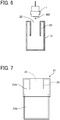
- FIG. 7 is a cross-sectional view of a liquid receptacle along the short-side direction thereof according to the third embodiment.
- the liquid receptacle 21 is constructed of two parts coupled together: an upper container 21A having an opening 22 and a flange 23; and a lower container 21B fitted to the upper container 21A.
- the liquid receptacle 21 can be easily manufactured by injection molding.
- FIG. 8 is a schematic plan view of a maintenance unit according to the fourth embodiment.
- the maintenance unit 2 illustrated in FIG. 8 includes a cap 25, a wiper 26, and a liquid receptacle 27 disposed in a housing 28.
- the cap 25 covers the nozzle face of the head 1.
- the wiper 26 wipes the nozzle face.
- the liquid receptacle 27 receives the liquid discharged in dummy discharge.
- the liquid receptacle 21 is removably attached to the outer face of the housing 28 of the maintenance unit 2.
- the liquid receptacle 21 includes engagement portions 31 and 32 to fit with bosses 28a and 28b (projections) of the housing 28, respectively, so that the liquid receptacle 21 can be attached to and detached from the housing 28.
- liquid receptacle 21 Since the liquid receptacle 21 is removably attached to the maintenance unit 2, only the liquid receptacle 21 can be easily replaced when the liquid receptacle 21 is full.
- the maintenance unit 2 includes the liquid receptacle 27 so that the liquid discharged in dummy discharge can be collected in the liquid receptacle 21 or 27.
- This structure enables separate use of the liquid receptacles 21 and 27 in accordance with contents of dummy discharge operation. For example, when the number of droplets discharged by dummy discharge is large and the amount of mist increases, the dummy discharge is performed to the liquid receptacle 27 that is far from the thread 101. Thus, adhesion of mist to the thread 101 can be inhibited.
- FIG. 9 is a perspective view of a structure of the liquid application unit relating to movement of one head, according to the first embodiment.
- the head 1 is mounted on a carriage 501 that can reciprocate in the direction indicated by arrow X, and the head 1 is moved between a home position where the head 1 is capped with the cap 25 of the individual maintenance unit 2 and a discharge position (dyeing position) where the head 1 discharges the liquid onto the thread 101.
- the carriage 501 is held by a main guide rod 502 and a sub-guide member 503 and reciprocally movable.
- the carriage 501 is provided with a driver 510 that reciprocates the carriage 501.
- the driver 510 includes a motor 511 and a crank 512 that is a drive force transmission member and moved by the motor 511.
- the carriage 501, the driver 510, and relating components serve as a head conveyor to move the head 1.
- a rear end of the crank 512 is rotatably attached, with a shaft 514, to an arm 513 coupled to a motor shaft 511a.
- a front end of the crank 512 is rotatably coupled to the carriage 501 by a support shaft 515.
- a tension coil spring 520 which is an elastic member, is disposed between the carriage 501 and a fixed portion.
- the tension coil spring 520 pulls the carriage 501 in the direction indicated by arrow A.
- Arrow Z indicates the direction of height.
- the carriage 501 In order to maintain and recover the head 1, the carriage 501 is repeatedly moved between the home position opposite the cap 25 that caps the head 1 and the discharge position where the liquid is applied to the thread 101 (liquid application target) for dyeing (printing) and stopped at the home position and the discharge position.
- the above-described structure regarding the movement of the head 1 according to the present embodiment can be used as the structure mentioned in the first embodiment, to move the head 1 between the discharge position (position of the thread 101) and the dummy discharge position Dp.
- FIG. 10 is a schematic view of the dyeing apparatus.
- a dyeing apparatus 1000 the embroidery head 106 in the liquid discharge apparatus 100 is replaced with a take-up reel 107 (a winder) to wind the thread 101 after dyeing.
- the dyeing apparatus 1000 supplies the thread 101 from the supply reel 102, discharges a liquid of a required color from the liquid application unit 103, dyes the thread 101 into a target color, and winds the dyed thread 101 with the take-up reel 107.
- liquid discharged from a liquid discharge head is not particularly limited as long as the liquid has a viscosity and surface tension of degrees dischargeable from the liquid discharge head.
- the liquid include a solution, a suspension, or an emulsion that contains, for example, a solvent, such as water or an organic solvent, a colorant, such as dye or pigment, a functional material, such as a polymerizable compound, a resin, or a surfactant, a biocompatible material, such as deoxyribonucleic acid (DNA), amino acid, protein, or calcium, or an edible material, such as a natural colorant.
Landscapes
- Engineering & Computer Science (AREA)
- Textile Engineering (AREA)
- Environmental & Geological Engineering (AREA)
- Chemical & Material Sciences (AREA)
- Materials Engineering (AREA)
- Health & Medical Sciences (AREA)
- General Health & Medical Sciences (AREA)
- Toxicology (AREA)
- Treatment Of Fiber Materials (AREA)
- Ink Jet (AREA)
Abstract
Description
- The present disclosure relates to a liquid discharge device, and a liquid discharge apparatus and a dyeing apparatus including the liquid discharge device.
- Apparatuses including a liquid discharge head discharge liquid that does not contribute to liquid application to a target, for maintenance and recovery of the liquid discharge head. The liquid not contributing to liquid application is discharged toward, for example, a liquid receptacle. Such an operation is called dummy discharge (also called flushing or purging).
-
JP-2007-152885-A - When the head discharges the liquid toward the ink receptacle as dummy discharge, if the position of dummy discharge is away from the position of liquid discharge to the target of liquid application (hereinafter "liquid application target"), downtime caused by the dummy discharge is long, which is inconvenient.
- In view of the foregoing, an object of the present disclosure is to enable an efficient dummy discharge operation.
- In order to achieve the above-described object, there is provided a liquid discharge device as described in appended claims. Advantageous embodiments are defined by the dependent claims.
- Advantageously, the liquid discharge device includes a head including a nozzle plate having a plurality of nozzles lined in a row and configured to discharge a liquid, and a liquid receptacle configured to receive the liquid discharged from the head. The liquid receptacle has an opening through which the liquid discharged from the head passes. A longitudinal direction of the opening is along a movement direction of a liquid application target to which the head applies the liquid. In a short-side direction of the opening, which is orthogonal to the movement direction, a width of the opening is greater than a width of the liquid application target.
- Advantageously, a liquid discharge apparatus includes the liquid discharge device and a conveyor defining a conveyance passage of the liquid application target. The conveyor is configured to convey the liquid application target.
- Accordingly, the dummy discharge operation can be performed efficiently.
- A more complete appreciation of the disclosure and many of the attendant advantages thereof will be readily obtained as the same becomes better understood by reference to the following detailed description when considered in connection with the accompanying drawings, wherein:
-
FIG. 1 is a schematic side view of a liquid discharge apparatus according to an embodiment of the present disclosure; -
FIG. 2 is a schematic view of a liquid application unit (a liquid application device) of the liquid discharge apparatus illustrated inFIG. 1 ; -
FIG. 3 is a plan view of a row of heads of the liquid application unit illustrated inFIG. 2 , as viewed from below; -
FIG. 4 is a plan view illustrating a liquid receptacle according to a first embodiment; -
FIG. 5 is a cross-sectional view illustrating the liquid receptacle illustrated inFIG. 4 , along a short-side direction thereof; -
FIG. 6 is a cross-sectional view illustrating a liquid receptacle according to a second embodiment, along a short-side direction thereof; -
FIG. 7 is a cross-sectional view illustrating a liquid receptacle according to a third embodiment, along a short-side direction thereof; -
FIG. 8 is a schematic plan view of a maintenance unit according to a fourth embodiment; -
FIG. 9 is a perspective view of a structure of the liquid application unit relating to movement of one head, according to the fourth embodiment; and -
FIG. 10 is a schematic view of a dyeing apparatus according to an embodiment of the present disclosure; and -
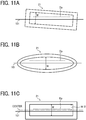
FIGS. 11A to 11C are plan views illustrating liquid receptacles according to variations of the structure illustrated inFIG. 4 . - The accompanying drawings are intended to depict embodiments of the present invention and should not be interpreted to limit the scope thereof. The accompanying drawings are not to be considered as drawn to scale unless explicitly noted.
- In describing embodiments illustrated in the drawings, specific terminology is employed for the sake of clarity. However, the disclosure of this patent specification is not intended to be limited to the specific terminology so selected, and it is to be understood that each specific element includes all technical equivalents that operate in a similar manner and achieve a similar result.
- Referring now to the drawings, wherein like reference numerals designate identical or corresponding parts throughout the several views thereof, and particularly to
FIGS. 1 to 3 , a liquid discharge apparatus according to an embodiment of this disclosure is described. As used herein, the singular forms "a", "an", and "the" are intended to include the plural forms as well, unless the context clearly indicates otherwise. -
FIG. 1 is a schematic view of the liquid discharge apparatus.FIG. 2 is a view of a liquid application unit of the liquid discharge apparatus.FIG. 3 is a view of a row of heads of the liquid application unit as viewed from below. - A
liquid discharge apparatus 100 inFIG. 1 is an in-line embroidery machine. Theliquid discharge apparatus 100 includes asupply reel 102 on which a thread 101 (a liquid application target) is wound, a liquid application unit 103 (a liquid application device), afixing unit 104, apost-treatment unit 105, and anembroidery head 106. - The
thread 101 drawn from thesupply reel 102 is guided byrollers embroidery head 106. - The liquid application unit 103 (the liquid discharge device) includes a plurality of heads 1 (1a to 1d) and a plurality of individual maintenance units 2 (2a to 2d) serving as maintenance devices. The
liquid application unit 103 discharges a liquid of a required color onto thethread 101 which is drawn out from thesupply reel 102. Theindividual maintenance units 2 perform maintenance of theheads 1, respectively. Theheads 1a to 1d discharge, for example, cyan (C), magenta (M), yellow (Y), and black (K) color liquids. - As illustrated in
FIG. 3 , each of the heads 1 (1a to 1d) includes anozzle plate 12 in which a plurality ofnozzles 11 to discharge a liquid is formed. Specifically, on a face (hereinafter "nozzle face") of thenozzle plate 12, the plurality ofnozzles 11 is lined in a row (a nozzle row 10). Eachhead 1 is disposed such that the direction (a nozzle row direction in which thenozzles 11 are lined) matches the direction of conveyance (movement direction) of thethread 101. - The
individual maintenance units 2 respectively include liquid receptacles 21 (21a to 21d, illustrated inFIG. 2 ) disposed opposite theheads 1 with the thread 101 (the liquid application target) interposed therebetween. - The
fixing unit 104 performs a fixing process (drying process) of thethread 101 to which the liquid is applied from theliquid application unit 103. Thefixing unit 104 includes, for example, a heater such as an infrared irradiation device and a hot air sprayer, and heats thethread 101 to dry. - The
post-treatment unit 105 includes, for example, a cleaning device that cleans thethread 101, a tension adjustment device that adjusts the tension of thethread 101, a feed amount detector that detects the amount of movement of thethread 101, and a lubricant application device that lubricates the surface of thethread 101. - The embroidery head 106 embroiders a pattern, for example, on a cloth with the
thread 101. - Although the liquid discharge apparatus in the present embodiment is an embroidery machine, the present disclosure is not limited thereto. Aspects of the present disclosure are applicable to devices, such as weaving machines and sewing machines, that use linear objects such as threads. Further, aspects of the present disclosure can be applied not only to apparatuses having a post-process, such as an embroidery machine, but also to dyeing apparatuses and the like that dye and wind threads, etc. as described later.
- Further, "thread" includes glass fiber thread, wool thread, cotton thread, synthetic thread, metal thread, wool, cotton, polymer, mixed metal thread, yarn, filament, and linear objects (continuous base materials) to which liquid is applicable. Thus, the "thread" also includes braids and flat cords (flat braids).
- Next, a first embodiment of the present disclosure is described with reference to
FIGS. 4 and 5. FIG. 4 is a plan view illustrating a liquid receptacle according to the present embodiment.FIG. 5 is a cross-sectional view illustrating the liquid receptacle along a short-side direction thereof. - The
liquid receptacle 21 is a box-shaped container having anopening 22 through which a liquid (droplet) 300 discharged from thehead 1 passes. - As illustrated in
FIG. 4 , the longitudinal direction of theopening 22 of theliquid receptacle 21 is along the movement direction (conveyance direction) of thethread 101 to which the liquid discharged from thehead 1 is applied. The "direction along the movement direction" is not limited to directions parallel to the movement direction but includes, for example, the direction illustrated inFIG. 11A . - In the
liquid receptacle 21, a width W (a short-side length) of theopening 22 is greater than a width W0 of the thread 101 (liquid application target) in the direction orthogonal to the movement direction, that is, the conveyance direction thereof (W>W0). - In the
liquid receptacle 21, a length L (a long-side length) of theopening 22 is longer than the length of thenozzle row 10 of thehead 1. - In the direction orthogonal to the conveyance direction of the thread 101 (orthogonal to the nozzle row direction), the
head 1 is movable between a discharge position opposite thethread 101 and a dummy discharge position not opposite the thread 101 (for example, a dummy discharge position Dp indicated by a broken line inFIG. 4 ). - That is, both the
head 1 at the discharge position and thehead 1 at the dummy discharge position Dp oppose theopening 22 of theliquid receptacle 21. Thehead 1 constantly oppose theopening 22 during the movement from the discharge position to the dummy discharge position and the movement from the dummy discharge position to the discharge position. - With this configuration, to apply the liquid 300 to the
thread 101, thehead 1 discharges the liquid 300 at the discharge position where thenozzle row 10 thereof is opposite thethread 101 illustrated inFIG. 4 . At this time, the liquid 300 that does not adhere to thethread 101 passes through theopening 22 of theliquid receptacle 21 positioned below and is collected in theliquid receptacle 21. - The dummy discharge from the
head 1 is performed as follows. At the dummy discharge position Dp indicated by the broken line inFIG. 4 , thehead 1 discharges the liquid 300 that does not adhere to thethread 101. In this time, the liquid 300 discharged in the dummy discharge also passes through theopening 22 of theliquid receptacle 21 positioned below and is collected in theliquid receptacle 21. - As described above, the
head 1 is kept opposed theopening 22 of theliquid receptacle 21 while moving from the discharge position to the dummy discharge position, to perform the dummy discharge. Accordingly, the dummy discharge can be performed at a position near the position where the liquid is applied to thethread 101. Accordingly, the distance by which thehead 1 moves for the dummy discharge is short, and the dummy discharge operation can be performed efficiently, reducing the downtime. - The
liquid receptacle 21 is disposed at a distance from the thread conveyance passage so that the thread 101 (the liquid application target) is contactless with theliquid receptacle 21. The thread conveyance passage is an example of a target conveyance passage and defined by therollers - Such an arrangement is advantageous when the liquid is applied to a target that is liquid-permeable, like the
thread 101, such that the time for the liquid to permeate from the landing side of the target to the opposite side is short. Since the target is contactless with theliquid receptacle 21, color bleeding can be inhibited. - Referring to
FIG. 2 , in the height direction, the liquid application target is disposed between thehead 1 and the liquid receptacle 21 (in particular, theopening 22 thereof). A distance Gb from the liquid application target (the thread 101) to theliquid receptacle 21 is longer than a distance Ga between thehead 1 and the liquid application target (the thread 101). - Such an arrangement can increase the accuracy of liquid landing position on the
thread 101. Additionally, securing the distance Gb from theliquid receptacle 21 to thethread 101 can reduce unintended dyeing of thethread 101 due to dirt accumulated in theliquid receptacle 21. - In the example described above, the shape of the opening of the liquid receptacle in plane (a shape in a plan view) is a rectangular shape having a short side and a long side, but the shape of the opening is not limited thereto. For example, the opening of the liquid receptacle can be elliptical in a plan view as illustrated in
FIG. 11B . - That is, the above-described the width W (the short-side length) of the
opening 22 is the length of theopening 22 in the direction orthogonal to the nozzle row direction of thehead 1. Therefore, the width W of theopening 22 in the direction orthogonal to the nozzle row direction of thehead 1 is set greater than the width W0 of the thread 101 (the liquid application target) in the direction orthogonal to the direction of movement of the thread 101 (W>W0). Such setting can provide the effects equivalent to those by the above-described embodiment. - Further, in the configuration in which the
head 1 is movable between the discharge position (where thethread 101 is located) and the dummy discharge position Dp in the direction orthogonal to the nozzle row direction as in the above embodiment, as illustrated inFIG. 4 , the width W of theopening 22 in the direction orthogonal to the nozzle row direction of thehead 1 is set greater than a distance W1 between the discharge position and the dummy discharge position Dp (W>W1). Such setting can provide the effects equivalent to those by the above-described embodiment. - Further, as illustrated in
FIG. 11C , in the short-side direction of the opening, the discharge position (the position of the thread 101) can be shifted to one side from the center, and the dummy discharge position Dp can be shifted to the other side (opposite to the discharge position) from the center. Such an arrangement enables more effective use of the area of theopening 22 and accordingly enables further reduction of the width of theopening 22 in the short-side direction. - In addition, these configurations can be combined with features of subsequent embodiments and a dyeing apparatus described later.
- Next, a second embodiment of the present disclosure is described with reference to
FIG. 6. FIG. 6 is a cross-sectional view of a liquid receptacle along the short-side direction thereof according to the second embodiment. - The
liquid receptacle 21 includes aflange 23 that extends down inward from the mouth defining theopening 22. - Mist arises from the liquid 30 entering the
liquid receptacle 21, and theflange 23 can reduce the amount of the mist scattering outside from theopening 22. - Next, a third embodiment of the present disclosure is described with reference to
FIG. 7. FIG. 7 is a cross-sectional view of a liquid receptacle along the short-side direction thereof according to the third embodiment. - The
liquid receptacle 21 is constructed of two parts coupled together: anupper container 21A having anopening 22 and aflange 23; and alower container 21B fitted to theupper container 21A. - Accordingly, the
liquid receptacle 21 can be easily manufactured by injection molding. - Next, a fourth embodiment of the present disclosure is described with reference to
FIG. 8. FIG. 8 is a schematic plan view of a maintenance unit according to the fourth embodiment. - The
maintenance unit 2 illustrated inFIG. 8 includes acap 25, awiper 26, and aliquid receptacle 27 disposed in ahousing 28. Thecap 25 covers the nozzle face of thehead 1. Thewiper 26 wipes the nozzle face. Theliquid receptacle 27 receives the liquid discharged in dummy discharge. - The
liquid receptacle 21 is removably attached to the outer face of thehousing 28 of themaintenance unit 2. For example, theliquid receptacle 21 includesengagement portions bosses housing 28, respectively, so that theliquid receptacle 21 can be attached to and detached from thehousing 28. - Since the
liquid receptacle 21 is removably attached to themaintenance unit 2, only theliquid receptacle 21 can be easily replaced when theliquid receptacle 21 is full. - Further, the
maintenance unit 2 includes theliquid receptacle 27 so that the liquid discharged in dummy discharge can be collected in theliquid receptacle liquid receptacles liquid receptacle 27 that is far from thethread 101. Thus, adhesion of mist to thethread 101 can be inhibited. - Next, a description is given of an example of a structure relating to the movement of the head according to the fourth embodiment, with reference to
FIG. 9. FIG. 9 is a perspective view of a structure of the liquid application unit relating to movement of one head, according to the first embodiment. - The
head 1 is mounted on acarriage 501 that can reciprocate in the direction indicated by arrow X, and thehead 1 is moved between a home position where thehead 1 is capped with thecap 25 of theindividual maintenance unit 2 and a discharge position (dyeing position) where thehead 1 discharges the liquid onto thethread 101. - In the present embodiment, the
carriage 501 is held by amain guide rod 502 and asub-guide member 503 and reciprocally movable. - The
carriage 501 is provided with adriver 510 that reciprocates thecarriage 501. Thedriver 510 includes amotor 511 and a crank 512 that is a drive force transmission member and moved by themotor 511. Thecarriage 501, thedriver 510, and relating components serve as a head conveyor to move thehead 1. - A rear end of the
crank 512 is rotatably attached, with ashaft 514, to anarm 513 coupled to amotor shaft 511a. A front end of thecrank 512 is rotatably coupled to thecarriage 501 by asupport shaft 515. - A
tension coil spring 520, which is an elastic member, is disposed between thecarriage 501 and a fixed portion. Thetension coil spring 520 pulls thecarriage 501 in the direction indicated by arrow A. Arrow Z indicates the direction of height. - With this structure, as the
motor 511 of thedriver 510 is driven, thecarriage 501 reciprocates along themain guide rod 502 and thesub-guide member 503 via thecrank 512. - In order to maintain and recover the
head 1, thecarriage 501 is repeatedly moved between the home position opposite thecap 25 that caps thehead 1 and the discharge position where the liquid is applied to the thread 101 (liquid application target) for dyeing (printing) and stopped at the home position and the discharge position. - The above-described structure regarding the movement of the
head 1 according to the present embodiment can be used as the structure mentioned in the first embodiment, to move thehead 1 between the discharge position (position of the thread 101) and the dummy discharge position Dp. - A description is given below of a dyeing apparatus according to an embodiment of the present disclosure, with reference to
FIG. 10. FIG. 10 is a schematic view of the dyeing apparatus. - In a
dyeing apparatus 1000, theembroidery head 106 in theliquid discharge apparatus 100 is replaced with a take-up reel 107 (a winder) to wind thethread 101 after dyeing. - The
dyeing apparatus 1000 supplies thethread 101 from thesupply reel 102, discharges a liquid of a required color from theliquid application unit 103, dyes thethread 101 into a target color, and winds the dyedthread 101 with the take-upreel 107. - In the present disclosure, "liquid" discharged from a liquid discharge head is not particularly limited as long as the liquid has a viscosity and surface tension of degrees dischargeable from the liquid discharge head. Examples of the liquid include a solution, a suspension, or an emulsion that contains, for example, a solvent, such as water or an organic solvent, a colorant, such as dye or pigment, a functional material, such as a polymerizable compound, a resin, or a surfactant, a biocompatible material, such as deoxyribonucleic acid (DNA), amino acid, protein, or calcium, or an edible material, such as a natural colorant.
Claims (12)
- A liquid discharge device (21,103) comprising:a head (1) including a nozzle plate (12) having a plurality of nozzles (11) lined in a row and configured to discharge a liquid; anda liquid receptacle (21) configured to receive the liquid discharged from the head (1), the liquid receptacle (21) having an opening (22) through which the liquid discharged from the head (1) passes,wherein a longitudinal direction of the opening (22) is along a movement direction of a liquid application target to which the head (1) applies the liquid, andwherein, in a direction orthogonal to the movement direction, a width of the opening (22) is greater than a width of the liquid application target.
- A liquid discharge apparatus (100) comprising:the liquid discharge device (21,103) according to claim 1; anda conveyor (108,109) defining a conveyance passage of the liquid application target, the conveyor (108,109) configured to convey the liquid application target.
- The liquid discharge apparatus (100) according to claim 2,
wherein the liquid application target is a linear object. - The liquid discharge apparatus (100) according to claim 2 or 3,
wherein the liquid receptacle (21) is at a distance from the conveyance passage of the liquid application target. - The liquid discharge apparatus (100) according to claim 2, 3, or 4,
wherein the conveyance passage of the liquid application target is between the head (1) and the opening (22) of the liquid receptacle (21) in a height direction of the liquid discharge apparatus (100), and
wherein a distance from the conveyance passage to the liquid receptacle (21) is longer than a distance between the head (1) and the conveyance passage in the height direction. - The liquid discharge apparatus (100) according to any one of claims 2 to 5, further comprising a head conveyor (501,510) configured to move the head (1), at least, between a discharge position opposite the conveyance passage, the discharge position at which the head (1) discharges the liquid, and a dummy discharge position away from the conveyance passage in a direction orthogonal to a nozzle row direction in which the plurality of nozzles is lined in the row,
wherein the opening (22) of the liquid receptacle (21) has a width greater than a distance from the discharge position to the dummy discharge position in the direction orthogonal to the nozzle row direction. - The liquid discharge apparatus (100) according to claim 6,
wherein the discharge position is shifted to one side from a center in a short-side direction of the opening (22), and the dummy discharge position is shifted to the other side from the center in the short-side direction of the opening (22). - The liquid discharge apparatus (100) according to any one of claims 2 to 7, further comprising a maintenance device (2) configured to maintain the head (1),
wherein the liquid receptacle (21) is detachably attached to the maintenance device (2). - The liquid discharge apparatus (100) according to claim 8, wherein the head (1) is movable between a discharge position opposite the conveyance passage, the discharge position at which the head (1) discharges the liquid, and a position opposite the maintenance device (2).
- The liquid discharge apparatus (100) according to any one of claims 2 to 9,
wherein the movement direction of the liquid application target matches a nozzle row direction, and
wherein the head (1) is one of a plurality of heads (1a, 1b, 1c, 1d) arranged along the movement direction of the liquid application target. - The liquid discharge apparatus (100) according to claim 10,
wherein the liquid receptacle (21) is one of a plurality of liquid receptacles (21a,21b,21c,21d) respectively for the plurality of heads (1a, 1b, 1c, 1d). - A dyeing apparatus (1000) comprising the liquid discharge device according to claim 1.
Applications Claiming Priority (2)
| Application Number | Priority Date | Filing Date | Title |
|---|---|---|---|
| JP2018248156 | 2018-12-28 | ||
| JP2019203605 | 2019-11-09 |
Publications (2)
| Publication Number | Publication Date |
|---|---|
| EP3674464A1 true EP3674464A1 (en) | 2020-07-01 |
| EP3674464B1 EP3674464B1 (en) | 2023-05-24 |
Family
ID=68848184
Family Applications (1)
| Application Number | Title | Priority Date | Filing Date |
|---|---|---|---|
| EP19215062.1A Active EP3674464B1 (en) | 2018-12-28 | 2019-12-11 | Liquid discharge device, and liquid discharge apparatus and dyeing apparatus including same |
Country Status (3)
| Country | Link |
|---|---|
| US (1) | US10974511B2 (en) |
| EP (1) | EP3674464B1 (en) |
| JP (1) | JP7388186B2 (en) |
Families Citing this family (5)
| Publication number | Priority date | Publication date | Assignee | Title |
|---|---|---|---|---|
| US11913152B2 (en) * | 2018-12-28 | 2024-02-27 | Ricoh Company, Ltd. | Liquid discharge apparatus, dyeing apparatus, embroidery machine, and maintenance device |
| JP7600807B2 (en) * | 2021-03-23 | 2024-12-17 | 株式会社リコー | Dyeing device, embroidery system, dyeing device control method, and dyeing device control program |
| US12436988B2 (en) | 2022-11-14 | 2025-10-07 | International Business Machines Corporation | Keyphrase generation |
| US12072841B2 (en) | 2022-11-14 | 2024-08-27 | International Business Machines Corporation | Keyphrase generation leveraging public repository categories |
| JP2024075227A (en) | 2022-11-22 | 2024-06-03 | 株式会社リコー | Liquid ejection device |
Citations (9)
| Publication number | Priority date | Publication date | Assignee | Title |
|---|---|---|---|---|
| US3863310A (en) * | 1969-08-11 | 1975-02-04 | Arnold Ochsner | Process for producing colored patterns in embroidery machines |
| US4029006A (en) * | 1975-06-26 | 1977-06-14 | The Boeing Company | Method and apparatus for printing indicia on a continuous, elongate, flexible three-dimensional member |
| JPH06304359A (en) * | 1993-04-23 | 1994-11-01 | Canon Inc | Sewing machine and its embroidery products |
| US5444466A (en) * | 1991-03-11 | 1995-08-22 | Electronic Cable Specialists, Inc. | Wire marking system and method |
| US6134924A (en) * | 1995-10-13 | 2000-10-24 | Ciba-Geigy Corporation | Apparatus for carrying out a process for the continuous dyeing of yarns with reactive dyes |
| US6189989B1 (en) * | 1993-04-12 | 2001-02-20 | Canon Kabushiki Kaisha | Embroidering using ink jet printing apparatus |
| JP2007152885A (en) | 2005-12-08 | 2007-06-21 | Fujifilm Corp | Image recording device |
| CH697623B1 (en) * | 2005-04-05 | 2008-12-31 | Textilma Ag | Textile machine formed as a ribbon needle loom, as knitting machine, sewing machine or as knitting machine, comprises a thread supply device having a color station, a thread processing device and/or a pattern control device |
| US20140053347A1 (en) * | 2010-12-21 | 2014-02-27 | Shaw Industries Group, Inc. | System and method for space-dyeing yarn |
Family Cites Families (12)
| Publication number | Priority date | Publication date | Assignee | Title |
|---|---|---|---|---|
| JP3066937B2 (en) * | 1993-04-12 | 2000-07-17 | キヤノン株式会社 | Inkjet dyeing embroidery method and apparatus |
| JPH06305129A (en) | 1993-04-23 | 1994-11-01 | Canon Inc | Ink jet printing apparatus and method and embroidering machine equipped with ink jet printing apparatus |
| JP2002035462A (en) * | 2000-07-31 | 2002-02-05 | Brother Ind Ltd | Automatic sewing color conversion sewing machine |
| JP2005103849A (en) | 2003-09-29 | 2005-04-21 | Konica Minolta Medical & Graphic Inc | Inkjet recording apparatus |
| JP4583896B2 (en) | 2004-12-03 | 2010-11-17 | 株式会社リコー | Image forming apparatus |
| JP5211859B2 (en) * | 2008-05-30 | 2013-06-12 | セイコーエプソン株式会社 | Fluid ejection device |
| JP6348841B2 (en) | 2011-09-14 | 2018-06-27 | インヴェンテック・ヨーロッパ・エイビーInventech Europe Ab | Coating apparatus for coating longitudinal substrates |
| SE538584C2 (en) | 2015-06-17 | 2016-09-27 | Inventech Europe Ab | Device and method for controlling the fixation of an in-linethread treatment |
| SE540990C2 (en) | 2015-06-17 | 2019-02-19 | Inventech Europe Ab | Device and method for in-line thread treatment |
| SE539534C2 (en) | 2016-03-07 | 2017-10-10 | Inventech Europe Ab | A system and method for in-line treatment of thread for use with a thread consumption device |
| SE539759C2 (en) | 2016-05-17 | 2017-11-21 | Inventech Europe Ab | A system for in-line treatment of thread |
| SE1651157A1 (en) | 2016-08-28 | 2018-02-20 | Inventech Europe Ab | A treatment unit for in-line treatment of threads |
-
2019
- 2019-12-11 EP EP19215062.1A patent/EP3674464B1/en active Active
- 2019-12-16 US US16/714,843 patent/US10974511B2/en not_active Expired - Fee Related
- 2019-12-26 JP JP2019235484A patent/JP7388186B2/en active Active
Patent Citations (9)
| Publication number | Priority date | Publication date | Assignee | Title |
|---|---|---|---|---|
| US3863310A (en) * | 1969-08-11 | 1975-02-04 | Arnold Ochsner | Process for producing colored patterns in embroidery machines |
| US4029006A (en) * | 1975-06-26 | 1977-06-14 | The Boeing Company | Method and apparatus for printing indicia on a continuous, elongate, flexible three-dimensional member |
| US5444466A (en) * | 1991-03-11 | 1995-08-22 | Electronic Cable Specialists, Inc. | Wire marking system and method |
| US6189989B1 (en) * | 1993-04-12 | 2001-02-20 | Canon Kabushiki Kaisha | Embroidering using ink jet printing apparatus |
| JPH06304359A (en) * | 1993-04-23 | 1994-11-01 | Canon Inc | Sewing machine and its embroidery products |
| US6134924A (en) * | 1995-10-13 | 2000-10-24 | Ciba-Geigy Corporation | Apparatus for carrying out a process for the continuous dyeing of yarns with reactive dyes |
| CH697623B1 (en) * | 2005-04-05 | 2008-12-31 | Textilma Ag | Textile machine formed as a ribbon needle loom, as knitting machine, sewing machine or as knitting machine, comprises a thread supply device having a color station, a thread processing device and/or a pattern control device |
| JP2007152885A (en) | 2005-12-08 | 2007-06-21 | Fujifilm Corp | Image recording device |
| US20140053347A1 (en) * | 2010-12-21 | 2014-02-27 | Shaw Industries Group, Inc. | System and method for space-dyeing yarn |
Also Published As
| Publication number | Publication date |
|---|---|
| JP7388186B2 (en) | 2023-11-29 |
| US10974511B2 (en) | 2021-04-13 |
| US20200207087A1 (en) | 2020-07-02 |
| JP2021075024A (en) | 2021-05-20 |
| EP3674464B1 (en) | 2023-05-24 |
Similar Documents
| Publication | Publication Date | Title |
|---|---|---|
| EP3674464B1 (en) | Liquid discharge device, and liquid discharge apparatus and dyeing apparatus including same | |
| US12070950B2 (en) | Liquid ejecting apparatus and cleaning device | |
| US9573375B2 (en) | Liquid ejecting apparatus and maintenance method | |
| US9789692B2 (en) | Liquid ejecting apparatus and cleaning device | |
| US20240253355A1 (en) | Inkjet recording device | |
| JP2025060640A (en) | Method for in-line processing of yarns and a system therefor comprising a processing unit and a control unit configured to determine whether a maintenance sequence is required - Patents.com | |
| CN115107366A (en) | Liquid ejecting apparatus, embroidery system, control method, and computer-readable storage medium | |
| EP4201680A1 (en) | Liquid discharge unit, liquid discharge apparatus, and linear medium treatment system | |
| US11939715B2 (en) | Liquid discharge device, liquid discharge apparatus, and dyeing apparatus | |
| JP2021112871A (en) | Device for discharging liquid, coloring device, embroidering device, liquid recovery method | |
| CN102152637B (en) | fluid ejection device | |
| JP2021112883A (en) | Discharge receiver, device that discharges liquid | |
| JP2023001350A (en) | Wiping device, maintenance device, and liquid jet device | |
| JP2022064780A (en) | Liquid discharge device, dyeing device | |
| JP6950729B2 (en) | Liquid injection device and cleaning device | |
| KR20110127078A (en) | Inkjet Printing Method and Inkjet Printing Device | |
| JP2023111316A (en) | Liquid ejector | |
| JP2022069138A (en) | Device that discharges liquid |
Legal Events
| Date | Code | Title | Description |
|---|---|---|---|
| PUAI | Public reference made under article 153(3) epc to a published international application that has entered the european phase |
Free format text: ORIGINAL CODE: 0009012 |
|
| STAA | Information on the status of an ep patent application or granted ep patent |
Free format text: STATUS: REQUEST FOR EXAMINATION WAS MADE |
|
| 17P | Request for examination filed |
Effective date: 20191211 |
|
| AK | Designated contracting states |
Kind code of ref document: A1 Designated state(s): AL AT BE BG CH CY CZ DE DK EE ES FI FR GB GR HR HU IE IS IT LI LT LU LV MC MK MT NL NO PL PT RO RS SE SI SK SM TR |
|
| AX | Request for extension of the european patent |
Extension state: BA ME |
|
| STAA | Information on the status of an ep patent application or granted ep patent |
Free format text: STATUS: EXAMINATION IS IN PROGRESS |
|
| 17Q | First examination report despatched |
Effective date: 20220916 |
|
| GRAP | Despatch of communication of intention to grant a patent |
Free format text: ORIGINAL CODE: EPIDOSNIGR1 |
|
| STAA | Information on the status of an ep patent application or granted ep patent |
Free format text: STATUS: GRANT OF PATENT IS INTENDED |
|
| RIC1 | Information provided on ipc code assigned before grant |
Ipc: B41J 11/00 20060101ALI20221104BHEP Ipc: B05B 5/14 20060101ALI20221104BHEP Ipc: D05C 11/24 20060101ALI20221104BHEP Ipc: B41J 3/407 20060101ALI20221104BHEP Ipc: B41J 2/165 20060101ALI20221104BHEP Ipc: D06P 5/30 20060101ALI20221104BHEP Ipc: D06B 11/00 20060101AFI20221104BHEP |
|
| INTG | Intention to grant announced |
Effective date: 20221213 |
|
| GRAS | Grant fee paid |
Free format text: ORIGINAL CODE: EPIDOSNIGR3 |
|
| GRAA | (expected) grant |
Free format text: ORIGINAL CODE: 0009210 |
|
| STAA | Information on the status of an ep patent application or granted ep patent |
Free format text: STATUS: THE PATENT HAS BEEN GRANTED |
|
| AK | Designated contracting states |
Kind code of ref document: B1 Designated state(s): AL AT BE BG CH CY CZ DE DK EE ES FI FR GB GR HR HU IE IS IT LI LT LU LV MC MK MT NL NO PL PT RO RS SE SI SK SM TR |
|
| REG | Reference to a national code |
Ref country code: GB Ref legal event code: FG4D |
|
| REG | Reference to a national code |
Ref country code: CH Ref legal event code: EP |
|
| REG | Reference to a national code |
Ref country code: DE Ref legal event code: R096 Ref document number: 602019029226 Country of ref document: DE |
|
| REG | Reference to a national code |
Ref country code: AT Ref legal event code: REF Ref document number: 1569537 Country of ref document: AT Kind code of ref document: T Effective date: 20230615 |
|
| P01 | Opt-out of the competence of the unified patent court (upc) registered |
Effective date: 20230517 |
|
| REG | Reference to a national code |
Ref country code: IE Ref legal event code: FG4D |
|
| REG | Reference to a national code |
Ref country code: LT Ref legal event code: MG9D |
|
| REG | Reference to a national code |
Ref country code: NL Ref legal event code: MP Effective date: 20230524 |
|
| REG | Reference to a national code |
Ref country code: AT Ref legal event code: MK05 Ref document number: 1569537 Country of ref document: AT Kind code of ref document: T Effective date: 20230524 |
|
| PG25 | Lapsed in a contracting state [announced via postgrant information from national office to epo] |
Ref country code: SE Free format text: LAPSE BECAUSE OF FAILURE TO SUBMIT A TRANSLATION OF THE DESCRIPTION OR TO PAY THE FEE WITHIN THE PRESCRIBED TIME-LIMIT Effective date: 20230524 Ref country code: PT Free format text: LAPSE BECAUSE OF FAILURE TO SUBMIT A TRANSLATION OF THE DESCRIPTION OR TO PAY THE FEE WITHIN THE PRESCRIBED TIME-LIMIT Effective date: 20230925 Ref country code: NO Free format text: LAPSE BECAUSE OF FAILURE TO SUBMIT A TRANSLATION OF THE DESCRIPTION OR TO PAY THE FEE WITHIN THE PRESCRIBED TIME-LIMIT Effective date: 20230824 Ref country code: NL Free format text: LAPSE BECAUSE OF FAILURE TO SUBMIT A TRANSLATION OF THE DESCRIPTION OR TO PAY THE FEE WITHIN THE PRESCRIBED TIME-LIMIT Effective date: 20230524 Ref country code: ES Free format text: LAPSE BECAUSE OF FAILURE TO SUBMIT A TRANSLATION OF THE DESCRIPTION OR TO PAY THE FEE WITHIN THE PRESCRIBED TIME-LIMIT Effective date: 20230524 Ref country code: AT Free format text: LAPSE BECAUSE OF FAILURE TO SUBMIT A TRANSLATION OF THE DESCRIPTION OR TO PAY THE FEE WITHIN THE PRESCRIBED TIME-LIMIT Effective date: 20230524 |
|
| PG25 | Lapsed in a contracting state [announced via postgrant information from national office to epo] |
Ref country code: RS Free format text: LAPSE BECAUSE OF FAILURE TO SUBMIT A TRANSLATION OF THE DESCRIPTION OR TO PAY THE FEE WITHIN THE PRESCRIBED TIME-LIMIT Effective date: 20230524 Ref country code: PL Free format text: LAPSE BECAUSE OF FAILURE TO SUBMIT A TRANSLATION OF THE DESCRIPTION OR TO PAY THE FEE WITHIN THE PRESCRIBED TIME-LIMIT Effective date: 20230524 Ref country code: LV Free format text: LAPSE BECAUSE OF FAILURE TO SUBMIT A TRANSLATION OF THE DESCRIPTION OR TO PAY THE FEE WITHIN THE PRESCRIBED TIME-LIMIT Effective date: 20230524 Ref country code: LT Free format text: LAPSE BECAUSE OF FAILURE TO SUBMIT A TRANSLATION OF THE DESCRIPTION OR TO PAY THE FEE WITHIN THE PRESCRIBED TIME-LIMIT Effective date: 20230524 Ref country code: IS Free format text: LAPSE BECAUSE OF FAILURE TO SUBMIT A TRANSLATION OF THE DESCRIPTION OR TO PAY THE FEE WITHIN THE PRESCRIBED TIME-LIMIT Effective date: 20230924 Ref country code: HR Free format text: LAPSE BECAUSE OF FAILURE TO SUBMIT A TRANSLATION OF THE DESCRIPTION OR TO PAY THE FEE WITHIN THE PRESCRIBED TIME-LIMIT Effective date: 20230524 Ref country code: GR Free format text: LAPSE BECAUSE OF FAILURE TO SUBMIT A TRANSLATION OF THE DESCRIPTION OR TO PAY THE FEE WITHIN THE PRESCRIBED TIME-LIMIT Effective date: 20230825 |
|
| PG25 | Lapsed in a contracting state [announced via postgrant information from national office to epo] |
Ref country code: FI Free format text: LAPSE BECAUSE OF FAILURE TO SUBMIT A TRANSLATION OF THE DESCRIPTION OR TO PAY THE FEE WITHIN THE PRESCRIBED TIME-LIMIT Effective date: 20230524 |
|
| PG25 | Lapsed in a contracting state [announced via postgrant information from national office to epo] |
Ref country code: SK Free format text: LAPSE BECAUSE OF FAILURE TO SUBMIT A TRANSLATION OF THE DESCRIPTION OR TO PAY THE FEE WITHIN THE PRESCRIBED TIME-LIMIT Effective date: 20230524 |
|
| PG25 | Lapsed in a contracting state [announced via postgrant information from national office to epo] |
Ref country code: SM Free format text: LAPSE BECAUSE OF FAILURE TO SUBMIT A TRANSLATION OF THE DESCRIPTION OR TO PAY THE FEE WITHIN THE PRESCRIBED TIME-LIMIT Effective date: 20230524 Ref country code: SK Free format text: LAPSE BECAUSE OF FAILURE TO SUBMIT A TRANSLATION OF THE DESCRIPTION OR TO PAY THE FEE WITHIN THE PRESCRIBED TIME-LIMIT Effective date: 20230524 Ref country code: RO Free format text: LAPSE BECAUSE OF FAILURE TO SUBMIT A TRANSLATION OF THE DESCRIPTION OR TO PAY THE FEE WITHIN THE PRESCRIBED TIME-LIMIT Effective date: 20230524 Ref country code: EE Free format text: LAPSE BECAUSE OF FAILURE TO SUBMIT A TRANSLATION OF THE DESCRIPTION OR TO PAY THE FEE WITHIN THE PRESCRIBED TIME-LIMIT Effective date: 20230524 Ref country code: DK Free format text: LAPSE BECAUSE OF FAILURE TO SUBMIT A TRANSLATION OF THE DESCRIPTION OR TO PAY THE FEE WITHIN THE PRESCRIBED TIME-LIMIT Effective date: 20230524 Ref country code: CZ Free format text: LAPSE BECAUSE OF FAILURE TO SUBMIT A TRANSLATION OF THE DESCRIPTION OR TO PAY THE FEE WITHIN THE PRESCRIBED TIME-LIMIT Effective date: 20230524 |
|
| REG | Reference to a national code |
Ref country code: DE Ref legal event code: R097 Ref document number: 602019029226 Country of ref document: DE |
|
| PLBE | No opposition filed within time limit |
Free format text: ORIGINAL CODE: 0009261 |
|
| STAA | Information on the status of an ep patent application or granted ep patent |
Free format text: STATUS: NO OPPOSITION FILED WITHIN TIME LIMIT |
|
| 26N | No opposition filed |
Effective date: 20240227 |
|
| PG25 | Lapsed in a contracting state [announced via postgrant information from national office to epo] |
Ref country code: SI Free format text: LAPSE BECAUSE OF FAILURE TO SUBMIT A TRANSLATION OF THE DESCRIPTION OR TO PAY THE FEE WITHIN THE PRESCRIBED TIME-LIMIT Effective date: 20230524 |
|
| PG25 | Lapsed in a contracting state [announced via postgrant information from national office to epo] |
Ref country code: SI Free format text: LAPSE BECAUSE OF FAILURE TO SUBMIT A TRANSLATION OF THE DESCRIPTION OR TO PAY THE FEE WITHIN THE PRESCRIBED TIME-LIMIT Effective date: 20230524 Ref country code: IT Free format text: LAPSE BECAUSE OF FAILURE TO SUBMIT A TRANSLATION OF THE DESCRIPTION OR TO PAY THE FEE WITHIN THE PRESCRIBED TIME-LIMIT Effective date: 20230524 |
|
| REG | Reference to a national code |
Ref country code: CH Ref legal event code: PL |
|
| PG25 | Lapsed in a contracting state [announced via postgrant information from national office to epo] |
Ref country code: LU Free format text: LAPSE BECAUSE OF NON-PAYMENT OF DUE FEES Effective date: 20231211 |
|
| PG25 | Lapsed in a contracting state [announced via postgrant information from national office to epo] |
Ref country code: MC Free format text: LAPSE BECAUSE OF FAILURE TO SUBMIT A TRANSLATION OF THE DESCRIPTION OR TO PAY THE FEE WITHIN THE PRESCRIBED TIME-LIMIT Effective date: 20230524 |
|
| REG | Reference to a national code |
Ref country code: BE Ref legal event code: MM Effective date: 20231231 |
|
| PG25 | Lapsed in a contracting state [announced via postgrant information from national office to epo] |
Ref country code: MC Free format text: LAPSE BECAUSE OF FAILURE TO SUBMIT A TRANSLATION OF THE DESCRIPTION OR TO PAY THE FEE WITHIN THE PRESCRIBED TIME-LIMIT Effective date: 20230524 Ref country code: LU Free format text: LAPSE BECAUSE OF NON-PAYMENT OF DUE FEES Effective date: 20231211 |
|
| REG | Reference to a national code |
Ref country code: IE Ref legal event code: MM4A |
|
| PG25 | Lapsed in a contracting state [announced via postgrant information from national office to epo] |
Ref country code: IE Free format text: LAPSE BECAUSE OF NON-PAYMENT OF DUE FEES Effective date: 20231211 |
|
| PG25 | Lapsed in a contracting state [announced via postgrant information from national office to epo] |
Ref country code: BE Free format text: LAPSE BECAUSE OF NON-PAYMENT OF DUE FEES Effective date: 20231231 |
|
| PG25 | Lapsed in a contracting state [announced via postgrant information from national office to epo] |
Ref country code: CH Free format text: LAPSE BECAUSE OF NON-PAYMENT OF DUE FEES Effective date: 20231231 |
|
| PG25 | Lapsed in a contracting state [announced via postgrant information from national office to epo] |
Ref country code: IE Free format text: LAPSE BECAUSE OF NON-PAYMENT OF DUE FEES Effective date: 20231211 Ref country code: CH Free format text: LAPSE BECAUSE OF NON-PAYMENT OF DUE FEES Effective date: 20231231 Ref country code: BE Free format text: LAPSE BECAUSE OF NON-PAYMENT OF DUE FEES Effective date: 20231231 |
|
| PG25 | Lapsed in a contracting state [announced via postgrant information from national office to epo] |
Ref country code: BG Free format text: LAPSE BECAUSE OF FAILURE TO SUBMIT A TRANSLATION OF THE DESCRIPTION OR TO PAY THE FEE WITHIN THE PRESCRIBED TIME-LIMIT Effective date: 20230524 |
|
| PG25 | Lapsed in a contracting state [announced via postgrant information from national office to epo] |
Ref country code: BG Free format text: LAPSE BECAUSE OF FAILURE TO SUBMIT A TRANSLATION OF THE DESCRIPTION OR TO PAY THE FEE WITHIN THE PRESCRIBED TIME-LIMIT Effective date: 20230524 |
|
| PG25 | Lapsed in a contracting state [announced via postgrant information from national office to epo] |
Ref country code: CY Free format text: LAPSE BECAUSE OF FAILURE TO SUBMIT A TRANSLATION OF THE DESCRIPTION OR TO PAY THE FEE WITHIN THE PRESCRIBED TIME-LIMIT; INVALID AB INITIO Effective date: 20191211 |
|
| PG25 | Lapsed in a contracting state [announced via postgrant information from national office to epo] |
Ref country code: HU Free format text: LAPSE BECAUSE OF FAILURE TO SUBMIT A TRANSLATION OF THE DESCRIPTION OR TO PAY THE FEE WITHIN THE PRESCRIBED TIME-LIMIT; INVALID AB INITIO Effective date: 20191211 |
|
| PG25 | Lapsed in a contracting state [announced via postgrant information from national office to epo] |
Ref country code: TR Free format text: LAPSE BECAUSE OF FAILURE TO SUBMIT A TRANSLATION OF THE DESCRIPTION OR TO PAY THE FEE WITHIN THE PRESCRIBED TIME-LIMIT Effective date: 20230524 |
|
| PGFP | Annual fee paid to national office [announced via postgrant information from national office to epo] |
Ref country code: DE Payment date: 20251211 Year of fee payment: 7 |
|
| PGFP | Annual fee paid to national office [announced via postgrant information from national office to epo] |
Ref country code: GB Payment date: 20251219 Year of fee payment: 7 |
|
| PGFP | Annual fee paid to national office [announced via postgrant information from national office to epo] |
Ref country code: FR Payment date: 20251229 Year of fee payment: 7 |