EP3674444A1 - An electrochemical process for producing magnetic iron oxide nanoparticles - Google Patents
An electrochemical process for producing magnetic iron oxide nanoparticles Download PDFInfo
- Publication number
- EP3674444A1 EP3674444A1 EP18248064.0A EP18248064A EP3674444A1 EP 3674444 A1 EP3674444 A1 EP 3674444A1 EP 18248064 A EP18248064 A EP 18248064A EP 3674444 A1 EP3674444 A1 EP 3674444A1
- Authority
- EP
- European Patent Office
- Prior art keywords
- iron oxide
- iron
- solution
- oxidant gas
- soluble
- Prior art date
- Legal status (The legal status is an assumption and is not a legal conclusion. Google has not performed a legal analysis and makes no representation as to the accuracy of the status listed.)
- Granted
Links
Images


Classifications
-
- C—CHEMISTRY; METALLURGY
- C25—ELECTROLYTIC OR ELECTROPHORETIC PROCESSES; APPARATUS THEREFOR
- C25B—ELECTROLYTIC OR ELECTROPHORETIC PROCESSES FOR THE PRODUCTION OF COMPOUNDS OR NON-METALS; APPARATUS THEREFOR
- C25B1/00—Electrolytic production of inorganic compounds or non-metals
- C25B1/01—Products
- C25B1/28—Per-compounds
- C25B1/30—Peroxides
-
- C—CHEMISTRY; METALLURGY
- C25—ELECTROLYTIC OR ELECTROPHORETIC PROCESSES; APPARATUS THEREFOR
- C25B—ELECTROLYTIC OR ELECTROPHORETIC PROCESSES FOR THE PRODUCTION OF COMPOUNDS OR NON-METALS; APPARATUS THEREFOR
- C25B1/00—Electrolytic production of inorganic compounds or non-metals
- C25B1/50—Processes
-
- C—CHEMISTRY; METALLURGY
- C25—ELECTROLYTIC OR ELECTROPHORETIC PROCESSES; APPARATUS THEREFOR
- C25B—ELECTROLYTIC OR ELECTROPHORETIC PROCESSES FOR THE PRODUCTION OF COMPOUNDS OR NON-METALS; APPARATUS THEREFOR
- C25B11/00—Electrodes; Manufacture thereof not otherwise provided for
- C25B11/02—Electrodes; Manufacture thereof not otherwise provided for characterised by shape or form
- C25B11/03—Electrodes; Manufacture thereof not otherwise provided for characterised by shape or form perforated or foraminous
- C25B11/031—Porous electrodes
- C25B11/032—Gas diffusion electrodes
-
- C—CHEMISTRY; METALLURGY
- C25—ELECTROLYTIC OR ELECTROPHORETIC PROCESSES; APPARATUS THEREFOR
- C25B—ELECTROLYTIC OR ELECTROPHORETIC PROCESSES FOR THE PRODUCTION OF COMPOUNDS OR NON-METALS; APPARATUS THEREFOR
- C25B13/00—Diaphragms; Spacing elements
- C25B13/04—Diaphragms; Spacing elements characterised by the material
- C25B13/08—Diaphragms; Spacing elements characterised by the material based on organic materials
-
- C—CHEMISTRY; METALLURGY
- C25—ELECTROLYTIC OR ELECTROPHORETIC PROCESSES; APPARATUS THEREFOR
- C25B—ELECTROLYTIC OR ELECTROPHORETIC PROCESSES FOR THE PRODUCTION OF COMPOUNDS OR NON-METALS; APPARATUS THEREFOR
- C25B9/00—Cells or assemblies of cells; Constructional parts of cells; Assemblies of constructional parts, e.g. electrode-diaphragm assemblies; Process-related cell features
- C25B9/17—Cells comprising dimensionally-stable non-movable electrodes; Assemblies of constructional parts thereof
- C25B9/19—Cells comprising dimensionally-stable non-movable electrodes; Assemblies of constructional parts thereof with diaphragms
Definitions
- the present invention relates to an electrochemical process for producing magnetic iron oxide nanoparticles with a desired saturation magnetization, from a solution of at least one soluble Fe n+ precursor salt in a solvent according to the preamble of the first claim.
- IONPs magnetic iron oxide nanoparticles
- iron oxide nanoparticles are determined by their physicochemical characteristics. Therefore, size, dispersity, composition, and structure, are amongst the aspects that must be precisely tailored for each specific use.
- Fe 3 O 4 is the iron oxide that exhibits the largest saturation magnetization (92 A m 2 kg -1 ) and a high Curie temperature (840 K) in the bulk ( Rochelle M Cornell and Udo Schwertmann, The iron oxides: structure, properties, reactions, occurrences and uses. John Wiley & Sons, 2003 ).
- the particle size becomes smaller than the magnetic domain size (approximately 25 nm-30 nm)
- magnetite transitions from ferrimagnetic to superparamagnetic ( Kannan M Krishnan, IEEE transactions on magnetics, 46(7):2523-2558, 2010 ).
- Iron oxide nanoparticles can exhibit close to bulk magnetization at relatively large sizes of around or above 20 nm. Further below the ferrimagnetic-superparamagnetic transition size, the saturation magnetization decreases ( ein Laurent, Delphine Forge, Marc Port, Alain Roch, Caroline Robic, Luce Vander Elst, and Robert N Muller, Chemical reviews, 108(6):2064-2110, 2008 ).
- IONPs as opposed to larger ferrimagnetic particles, are better suited for preparing stable dispersions, a key feature for various applications.
- Of crucial importance in the optimization of IONP synthesis is the ability to control the phase composition of the IONP, and the ability to synthesise ⁇ 20 nm particles with a narrow particle size distribution, i.e.
- optimal magnetization may be achieved, while fine control over the phase composition (Fe 3 O 4 vs. ⁇ -Fe 2 O 3 ) may enable the formulation of precise structure-property relations ( Yury V Kolenko, et. alThe Journal of Physical Chemistry C, 118(16): 8691-8701, 2014 ).
- US8940179 discloses a method for preparing magnetite nanoparticles from low-grade iron ore, comprising the steps of :
- the method disclosed in US8940179 however presents the disadvantage that one single reaction product is produced, i.e., magnetite with a defined set of immovable characteristics. Moreover, the method does not permit producing other forms of iron oxides, it does not permit controlling the stoichiometry, and other relevant physicochemical properties of the iron oxides, such as the precise chemical composition, the oxidation state of the iron in the oxides produced, the crystallite size of the nanoparticles, the lattice parameters of the iron oxide crystals, the concentration of defects (i.e., vacancies), and the saturation magnetization.
- US20130126394A1 discloses a method of preparing magnetic iron oxide nanoparticles, comprising the steps of:
- the method disclosed in US20130126394A1 however relies on the co-precipitation reaction of specific iron salts, in particular water soluble ferric- and ferrous- salts, in a specific molar ratio of 1:2.
- the magnetic iron oxide particles produced have an average particle diameter of 1000-1400 nm, and can therefore not be formally classified as nanoparticles which are typically defined as particles with an average particle size of below 100 nm.
- US20080003159A1 discloses a method for producing single component magnetic or metal oxide nanoparticles, which comprises:
- the surfactant is used to stabilize the magnetic or metal oxide nanoparticles, and is added in an amount of 8-50 times that of the precursor.
- the solvent is added in an amount of 5-40 times that of the precursor.
- the size of the magnetic oxide nanoparticle can be controlled by the concentration of the magnetic precursor, and the higher concentration of the precursor the size of the magnetic oxide nanoparticle.
- the diameter of the metal oxide nanoparticles can be controlled by the nature and concentration of the surfactant.
- the present invention therefore seeks to provide a process for the production of magnetic iron oxide nanoparticles with a desired degree of magnetization, which permits to control at the same time the particle size, the stoichiometry and Fe speciation of the iron oxide nanoparticles obtained from that process.
- the present invention relates to an electrochemical process for producing from a solution of at least one soluble Fe n+ precursor salt in a solvent, magnetic iron oxide nanoparticles with a desired saturation magnetization, the process comprising the steps of
- the present invention provides a one step, process for converting a dissolved Fe n+ precursor salt into nanoparticles of one or more magnetic iron oxides with a desired or defined stoichiometry, which may be carried out in one single reactor.
- the precursor salt may contain exclusively Fe ions in the divalent state as Fe 2+ , but the precursor salt may also comprise a mixture of iron salts with Fe ions in different oxidation states. Usually these oxidation states will be higher than 2+. However, the skilled person can recognize that the use of an elemental Fe0 sacrificial anode is possible for the provision of such oxidized states (i.e., by anodic dissolution).
- the process of the present invention permits producing from an iron salt, one or more iron oxide reaction products which are magnetic and have a desired degree of magnetization, and which have a desired, tailored stoichiometry.
- the present invention in particular permits tailoring the oxidation state of the Fe atoms (i.e., Fe speciation) of which the magnetic iron oxide is composed, as well as the concentration of each Fe-atom of a certain oxidation state within the iron oxide reaction product.
- the process of this invention permits producing iron oxides which contain a desired amount of one or more iron atoms or a mixture of iron atoms in a desired oxidation state.
- the process of this invention permits producing iron oxides with magnetic properties, with a desired degree of magnetization.
- the present invention additionally presents the advantage that the process permits to additionally control the particle size, crystallite size, lattice parameter and concentration of vacancies in the magnetic iron oxide nanoparticles.
- the iron oxides produced may range from maghemite to magnetite, i.e., iron oxides may be obtained with a stoichiometric composition ranging from Fe(III) 2.67 O 4 to Fe(II)Fe(III) 2 O 4 , in particular from Fe(II) 0.22 Fe(III) 2.52 O 4 to Fe(II) 0.76 Fe(III) 2.16 O 4 .
- iron oxides may be produced with a desired saturation magnetization, in particular the saturation magnetization may be tailored to range from 15 to 100 Am 2 kg -1 , preferably from 20 to 92 Am 2 kg -1 , more preferably between 23 and 73 Am 2 kg -1 .
- the method of the present invention also permits producing solid powders or dispersions of the naked or capped magnetic iron oxides.
- the reaction product may therefore be used either the way it has been produced, it may be freed of water and dried, shielding agents may be added to shield the oxides from the solution (or its remainders), for example to counteract particle agglomeration and growth or to achieve a certain function at the particle surface.
- the selected O 2 mole fraction range employed in the process of this invention ensures that the reactants needed to achieve oxidation of the Fe n+ into iron oxide with a higher oxidation state and saturation magnetization, in particular OH- and H 2 O 2 , are formed in situ in the electrolyte (catholyte).
- the inventors confirmed that the reduction of the O 2 containing oxidant gas at the cathode gives rise to the formation of at least OH- and peroxide species or intermediates, which are needed to obtain iron oxides with a sufficiently high oxidation state, so that the magnetic Fe 2 O 3 oxide may be formed.
- the inventors have also observed that electrochemical potentials leading to current densities below 10 Am -2 slow down the production of the oxidizing agents that lead to the oxidation reaction and promote formation of iron oxide particles above nanoparticle size ranges. With this low charge applied, the time needed to obtain the desired forms of iron oxide would significantly increase to values that are no longer economically feasible, and mainly lead to the formation of under-oxidized species, a.o., FeO(OH) species.
- the risk increases to the formation of iron oxides which do not show the desired saturation magnetization, like FeOOH and Fe 2 O 3 .
- the time during which current is applied should be carefully selected to limit oxidation to a desired extent.
- the skilled person will be capable of selecting the time during which the current is applied, i.e., of selecting the charge applied, taking into account the other circumstances prevailing in the reaction mixture, the nature of the iron oxide to be produced and the saturation magnetization desired.
- the electrochemical potential to which the gas-diffusion cathode is subjected is a reducing potential relative to a reference electrode, preferably below the thermodynamic pH-potential equilibrium region of stability of the O 2 oxidant gas in the reaction medium preferably a reducing potential relative to a reference electrode, which is below the thermodynamic pH potential equilibrium region of stability of the oxidant gas O 2 in water.
- the pH may change in the course of the reaction, which may involve the need to adapt the electrochemical potential in the course of the reaction so that it remains below the thermodynamic limits of O 2 reduction at a pH prevailing in the cathode compartment.
- the electrochemical potential is preferably selected such that it is below the region of thermodynamic stability of water and outside of the region of thermodynamic stability of hydrogen. This way the risk to the occurrence of water electrolysis to form hydrogen may be minimized.
- reaction mixture contains a mixture of Fe 3+ and Fe 2+
- magnetite Tet [Fe 3+ ] Oct [Fe 2+ 1-3 ⁇ Fe 3+ 1+2 ⁇ ⁇ ⁇ ]O 4 (wherein ⁇ refers to the content of vacancies in the structure) is enabled, as described by reaction 8 below : Fe 2+ (aq) + 2Fe 3+ (aq) + 8OH - (aq) ⁇ Fe 3 O 4 (s) + 4H 2 O(l)
- a common mechanism during co-precipitation processes involves the formation of goethite Fe III OOH as represented by reaction 9, followed by a topotactic transformation to magnetite if in the presence of ferrous ions as shown in reaction 10 : Fe 3+ (aq) + 3OH - (aq) ⁇ FeOOH(s) + H 2 O(l) (9)
- the solution of at least one soluble Fe n+ precursor salt in a solvent is a solution comprising at least one soluble Fe 2+ precursor salt.
- the at least one soluble Fe n+ precursor salt contains a mixture of Fe 3+ and Fe 2+ salts.
- the presence of a single Fe n+ precursor in the catholyte is preferred, as it facilitates controlling the reactions that take place and therefore the product formed, and makes the process more economic.
- the concentration of the at least one soluble Fe n+ precursor salt in the reaction medium is below 20.0 mM, preferably below 10.0 mM.
- Selection of an appropriate concentration in the afore-mentioned range will permit to tailor both the size of the iron oxide crystals and the iron oxide particles formed. In particular it has been observed that an increasing concentration of the soluble Fe n+ precursor salt in the reaction medium favours formation of larger crystals.
- selection of an appropriate concentration within the afore-mentioned range permits to tailor the crystallite size in a range between 5 and 20 nm, preferably between 5.5 and 18.5 nm.
- selection of an appropriate concentration permits to tailor the particle size of the magnetic iron oxide in a range between 20 and 75 nm, preferably between 20 and 55 nm, more preferably between 35 and 55 nm.
- the concentration of the at least one soluble Fe n+ precursor salt in the solution ranges between 0.001 mM and 20.0 mM, preferably between 0.01 mM and 20.0 mM, more preferably between 0.1 mM and 20.0 mM, most preferably between 1.0 and 20.0 mM.
- Concentrations below 1.0 mM generally lead to low yields of magnetic iron oxides, whereas with concentrations above 20 mM the risk increases to crystal aggregation and the formation of larger iron oxide particles of micro meter size which risk to clog the electrochemical cell and have a limited stability in relation to particle size.
- the saturation magnetic hysteresis has been found to depend on the crystallite and particle size, as well as on the lattice parameter, and the concentration of vacancies, which are in turn controlled by the iron precursor concentration.
- the concentration of the soluble iron precursor salt as described above additionally the chemical composition, stoichiometry, oxidation state, and lattice parameter of the iron oxide crystallites may be controlled by varying the concentration of the water soluble iron precursor salt in the aqueous solution between 1 and 10 mM.
- concentration of the water soluble iron precursor salt in the aqueous solution between 1 and 10 mM.
- the concentration of the soluble Fe n+ precursor salt in the catholyte may for example be varied by varying the rate with which the soluble Fe n+ precursor containing catholyte is supplied to the cathode. Such variation will in particular be done when variation of the crystal size of the reaction product is envisaged, since varying the concentration of the Fe n+ precursor salt permits varying the crystal size of the reaction product, as well as the particle size.
- iron oxide particles with a desired stoichiometry and particle size may be achieved by operating the process of this invention with a catholyte supply rate that ranges between 5.0 and 150.0 ml/min, preferably between 5.0 and 100.0 ml/min, most preferably between 5.0 and 50 ml/min. Higher the supply rates generally lead to magnetic iron oxide particles with a smaller particle size, whereas lower supply rates lead to magnetic iron oxide particles with a larger particle size. Thus by varying the catholyte supply rate, the average particle size of the iron oxide particles may be tuned, as well as their effective surface area.
- the pH of the catholyte is preferably adjusted to a value which ranges between 2.0 and 6.0, preferably between 2.0 and 5.0, more preferably between 2.5 and 3.5 to achieve a sufficiently high yield of precipitated iron oxide particles.
- the pH is smaller than the pH range within which a relative predominance exists of the iron precursor in the ionic form.
- the pH is namely smaller than the pKa of the Fe n+ precursor salt.
- the method of this invention may be carried out in aqueous solution, which only contains water as the liquid phase or solvent.
- the method of this invention may however also be carried out in a liquid phase or solvent which contains a mixture of water and one or more organic solvents, or in an organic solvent or a mixture of two or more organic solvents.
- the process of this invention may be carried out in water or a polar organic solvent for the at least one Fe n+ oxide or in an apolar organic solvent, or a mixture of two or more of the afore-mentioned solvents.
- the skilled person will be capable of selecting the most appropriate solvent, taking into account a.o. the particle size to be achieved and the envisaged application of the iron oxide.
- An appropriate selection of the solvent will permit controlling the dimensions of the magnetic iron oxide particles.
- the inventors have namely observed that the use of water as the solvent or a polar organic solvent favours crystallite and particle aggregation and may give rise to the formation of particles with a larger average particle size. Therefore, such solvents will generally be used when the formation of larger iron oxide particles is envisaged.
- the use of an apolar organic solvent counteracts particle aggregation and may give rise to the formation of particles with a smaller average crystal and particle size often smaller than 20 nm and preferably smaller than 10 nm).
- an apolar organic solvent may be preferred.
- the nature of the solvent may further be varied taking into account the envisaged application, for example in case biocompatibility is desired. In this case water will still be the preferred solvent.
- the process of this invention is suitable for use with a wide variety of iron precursor salts.
- the nature of the soluble iron precursor salt may be varied and may be for example be selected from the group of a chloride, nitrate, sulfate, phosphate, perchlorate or a mixture comprising two or more of the afore-mentioned compounds. It shall however be clear that other precursor salts known to the skilled person may be used as well. It has been observed that different geometries of the nanoparticles may be obtained (e.g., triangular, spherical, etc.) by varying the nature of the soluble iron precursor salt.
- the oxidant gas used in the process of this invention may consist of pure O 2 or a mixture of O 2 with one or more other gases, which preferably are inert to the electrochemical reaction, in particular N 2 , or a noble gas, more particularly Ar.
- a mixture of gases e.g., O 2 and N 2
- the skilled person will be capable of adjusting the partial pressure of the oxidant gas in such a way that it is sufficiently high to enable its electrochemical reduction, as low oxygen partial pressures may limit the extent of reaction due to production of O containing species with low reactivity and/or give rise to the formation of too small crystals and too small nanoparticles.
- the rate with which the O 2 containing oxidant gas is supplied to the cathode is preferably variable.
- a supply rate with which the oxidant gas is supplied to the gas diffusion electrode ranges between 5.0 and 300.0 ml/min, preferably between 5.0 and 250.0 ml/min, more preferably between 5.0 and 150.0 ml/min.
- a partial pressure of the oxidant gas that is supplied to the gas diffusion electrode is variable.
- the O 2 mole fraction in the O 2 containing oxidant gas is at least 0.15, preferably at least 0.20, more preferably at least 0.21.
- the O 2 partial pressure in the oxidant gas ranges between 0.20 and 1.0.
- the working potential of the cathode is set at a value between -50.0 and -750 mV vs. Ag/AgCl, preferably at a value between -100.0 and -650 mV, more preferably between -250 and -500 mV, as within these ranges iron oxides with the desired stoichiometry, with iron in a desired oxidation state for iron oxides with magnetic properties, may be obtained. It has been observed that by varying the electric or electrochemical potential at the cathode, the oxidation state of the Fe ions in the iron oxide or iron oxides formed, may be controlled, and iron oxide may be formed which vary from maghemite to magnetite. Working potentials more negative than -750 mV are generally not preferred as they support formation of hydrogen, reducing the efficiency of the targeted reactions.
- the process of this invention is carried out in a catholyte with an ionic conductivity that is sufficiently high, to ensure that the electrochemical conversion proceeds sufficiently fast to permit keeping the average size of the iron oxide crystals small and limiting crystal aggregation to form larger particles within a desired extent.
- a catholyte with and an ionic conductivity of at least 1.0 mS/cm, preferably at least 10 mS/cm. This conductivity may be achieved by the addition of a supporting electrolyte, such as but not limited to, NaCl.
- the electrolytic conductivity may be increased to at least 5, preferably to at least 10, more preferably between 20 and 80 and even more preferably between 20 and 50 mS.cm -1 and thereby the risk to a varying conductivity as a result of the removal of the reactant iron precursor salt due to its oxidation may be minimised.
- an amount of a weak protonic electrolyte may be supplied to the catholyte.
- the weak protonic electrolyte is assumed to act as a catalyst or co-catalyst in the formation of reactive peroxide and/or radical species from the oxidant gas at the cathode, and to accelerate the oxidation of the iron ion of the soluble iron precursor salt. Addition of the weak protonic electrolyte may not only increase the conductivity of the catholyte, but that it may also increase the current density over the cathode.
- the presence of the weak protonic electrolyte has the effect that variations in the pH of the catholyte in the course of the oxidation reaction may be reduced to a minimum. This contributes to minimizing the risk to the occurrence of unwanted side reactions which would lead to the formation of nonmagnetic iron oxides.
- the amount of weak protonic electrolyte may vary within wide ranges but is preferably not less than a 10 mM solution and preferably not more than a 1.5 M solution, more preferably the concentration of the weak electrolyte varies between 10 and 500 mM, most preferably around 100 mM.
- the weak protonic electrolyte will usually be a weak protonic acid.
- a weak protonic acid is a protonic acid which only partially dissociates in water : HA aq ⁇ H + aq + A ⁇ aq
- a weak polyprotonic acid is a weak acid which has more than one ionisable proton per molecule.
- Preferred weak protonic acids for use with the present invention have a pKa of between 2.0 and 6.0, preferably between 3.0 and 5.0, more preferably about 3.0.
- Examples of weak protonic acids suitable for use with the present invention include those selected from the group of weak organic and weak inorganic acids, in particular acetic acid, citric acid, oxalic acid, lactic acid, gluconic acid, ascorbic acid, formic acid, glycolic acid, potassium monohydrogen phosphate, potassium dihydrogen phosphate, ammonium chloride, boric acid, sodium hydrogen sulphate, sodium hydrogen carbonate, ammonium chloride, and mixtures of two or more hereof.
- the weak protonic acid may be a monoprotonic acid, but preferably is a polyprotonic acid.
- Particularly preferred weak protonic acids are those having a pKa which is at least one unit higher than the pH of the catholyte at the initial processing conditions.
- the electrolyte may further contain a surfactant, capping agent or stabilizer additive.
- the electrochemically active material of the gas diffusion electrode which forms part of the cathode used in the process of this invention preferably comprises an active surface having a plurality of active sites with a weak protonic acid functionality, i.e. active sites which only partially dissociate in water.
- Various electrochemically active materials may be used to achieve this. Preferred are those materials which have a surface comprising protonic acid functional groups. Particularly preferred are those materials which comprise electrically conductive particles of carbonaceous origin, more preferably those comprising electrically conductive particles of carbonaceous origin with a catalytically active surface comprising a plurality of protonic acid groups.
- the protonic acidic functional groups present on the catalytically active surface may partly dissociate at a corresponding pH.
- the inventors also believe that the thus dissociated surface groups have a high oxygen affinity and thus intervene in the oxidation of the metal ion or the metalloid ion.
- porous materials in particular those which contain weak protonic acid functional groups.
- porous metals and metalloids for example porous nickel or copper, porous carbon based materials, porous ion exchange resins, carbon aerogels, silicon, conductive polymers, conductive foams or conductive gels, among others.
- porous carbon based material as or in the electrochemically active surface is preferred, because of its catalytic activity in combination with a reasonable cost and abundant availability in comparison to other materials.
- suitable materials include graphite, carbon nanotubes, graphene, carbon black, acetylene black, activated carbon or synthetic carbons such as vulcan.
- Other electrochemically active materials suitable for use with this invention include carbonaceous materials the surface of which has been chemically modified to adapt its catalytic activity and compatibility with the reaction medium. Without wanting to be bound by this theory, it is believed that the presence of oxygen-containing functional groups support the oxidation reaction. Particularly preferred carbon materials have a surface with quinone-type functional groups.
- Suitable porous material for use as the electrochemically active layer of the gas diffusion electrode preferably have a high specific surface area as measured by the BET method described in ASTM D5665, in particular a BET surface area of at least 50 m 2 /g, preferably at least 100 m 2 /g, more preferably at least 200 m 2 /g, most preferably at least 400 or 500 m 2 /g, but those having a surface area larger than 750 or 1000 m 2 /g or even more may be particularly preferred.
- Porous materials particularly suitable for use as the electrochemically active layer include carbonaceous particles selected from the group of graphite, carbon nanotubes, graphene, carbon black, activated carbon or synthetic carbons.
- Preferred conductive carbonaceous particles have a BET surface area of at least 50 m 2 /g, preferably at least 100 m 2 /g, more preferably at least 200 or 250 m 2 /g, most preferably at least 400 or 500 m 2 /g, but those having a surface area larger than 750 or 1000 m 2 /g or even more may be particularly preferred.
- Suitable porous material for use as the electrochemically active layer preferably form a continuous layer on the cathode.
- use can be made of a polymer material which functions as a support for the electrochemically active material.
- the electrochemically active porous material is a solid which is dispersible or flowable in the water based electrolyte.
- the solid may be made of one or more of the above described materials.
- a cathode comprising a porous gas diffusion electrode, wherein one side of the gas diffusion electrode comprises a layer of at least one electrochemically active material active for or capable of catalyzing the reduction of oxygen to hydrogen peroxide.
- electrochemically active material for or capable of catalyzing the reduction of oxygen to hydrogen peroxide.
- Preferred active materials have been described above.
- convective mass transfer may be created at least in the cathodic gas compartment.
- the present invention also relates to an iron oxide with a desired saturation magnetisation, which responds to the chemical formula or stoichiometric composition ranging from Fe(III) 2.67 O 4 to Fe(II)Fe(III) 2 O 4 , in particular from Fe(II) 0.22 Fe(III) 2.52 O 4 to Fe(II) 0.76 Fe(III) 2.16 O 4 , obtainable with the method of this invention.
- the saturation magnetization of such iron oxides as measured with a Vibrational Sample Magnetometer (VSM) generally ranges from 20 to 92 Am 2 kg -1 , preferably between 23 and 73 Am 2 kg -1 . In a preferred embodiment, these magnetic iron oxides are obtained with the process of this invention described above.
- the present invention further relates to an iron oxide with a desired saturation magnetisation, which responds to the chemical formula or stoichiometric composition ranging from Fe(III) 2.67 O 4 to Fe(II)Fe(III) 2 O 4 , in particular from Fe(II) 0.22 Fe(III) 2.52 O 4 to Fe(II) 0.76 Fe(III) 2.16 O 4 , obtainable with the method of this invention provided with a coating, e.g., to contain products to be released on-demand, to achieve core-shell structures, etc.
- the present invention also relates to a composition
- a composition comprising at least one aggregate particle of nano crystals of one or more magnetic iron oxides obtained by the process described above wherein the iron oxide nano crystals have a crystal size of between 0.2 and 30.0 nm.
- the nano crystals will usually have a lattice parameter of between 1.0 and 18.0 nm, and any aggregate particles formed will have an average particle size of ⁇ 30 nm.
- the reaction product may take the form of a dispersion of the reaction product in the reaction medium or solvent, with a solids content of between 1.0 and 30.0 wt. %, preferably between 5.0 and 10.0 wt. %.
- the aqueous medium may comprise the electrolyte, an organic solvent, water, etc.
- the reaction product obtained according to the present invention in the form of nano crystals, may have a wide variety of uses. Possible uses include, without being limited thereto, the use in contrast agents for magnetic resonance imaging (MRI), diagnostics, energy applications such as capacitors, super-capacitors, batteries, as well as their use as catalysts.
- MRI magnetic resonance imaging
- diagnostics energy applications such as capacitors, super-capacitors, batteries, as well as their use as catalysts.
- energy applications such as capacitors, super-capacitors, batteries, as well as their use as catalysts.
- the present invention presents many advantages.
- the present invention provides a single-step process which allows for fast processing times, use of limited reactor space and an easy to control process.
- the process of this invention may be carried out using a single iron precursor Fe 2+ , allowing for a better control of the reactions and of the properties of the nanoparticles. If so desired however, the method of this invention may use a mixture of two or more precursors Fe 2+ and Fe 3+ .
- Alkaline reaction conditions are generated in situ, through an electrochemical (heterogeneous) process, this being substantially more economical than a process in which chemical base needs to be added.
- iron oxide may be produced, with high control of stoichiometry, oxidation state, crystallite size, lattice parameter, and saturation magnetization.
- the stoichiometry and valence state of the IONPs may be controlled and a range or IONPs may be produced varying from Fe(OH) 2 , Fe 3 O 4 , ⁇ -Fe 2 O 3 , to FeOOH.
- the structure, stoichiometry and valence state of magnetite can be controlled i.e., Tet [Fe 3+ ] Oct [Fe 2+ 1-3 ⁇ Fe 3+ 1+2 ⁇ ⁇ ⁇ ]O 4 , wherein ⁇ refers to vacancies, ⁇ refers to the content of vacancies in the structure, and the scripts "tet” and "oct” refer to tetrahedral and octahedral structural sites, respectively, and ⁇ 0 wherein ⁇ 0 represents iron-deficient magnetite.
- H 2 O 2 needed to oxidize Fe(II) to Fe(III) is generated in-situ as well as other strong oxidizing agents that can replace the function of the chemically-added H 2 O 2 , such as O 2- or its radical, among others.
- the process of the present invention does not need to make use of highly-reactive reducing agents like borohydrides (NaBH 4 and even worse, LiBH 4 ). These are extremely effective, but also very reactive and have to be kept away from moisture and other environmental agents. It's a cumbersome chemical to handle and use. Our method does not use any of these or equivalent reagents.
- highly-reactive reducing agents like borohydrides (NaBH 4 and even worse, LiBH 4 ).
- the process of this invention can be carried out at relatively low temperatures, i.e. below 70 °C, and more preferably room temperature (i.e., 18 -30 °C), and is therefore energy saving.
- the process of this invention may be carried out at elevated pressures above atmospheric pressure, but is preferably carried but at atmospheric pressure.
- the iron oxide nanoparticles obtained with the method of this invention may have controlled properties in relation to stoichiometry, composition, lattice parameter and saturation magnetization, beyond particle size only.
- Some features of utmost important to define a precise iron oxide nanoparticles synthetic identity are: nanoparticle size, crystallite (grain) size, lattice parameter, valence state, stoichiometry, structure, morphology. Ideally, monodispersity for all these features should be achieved to reproducibly yield a certain function or activity. Most prior art only shows control in particle size and its monodispersity.
- the process of the present invention may be carried out in one single reactor, which means that the oxidation and precipitation steps may be carried out in one single reactor and take place through a unique process, for compactness, energy and chemical efficiency, and process control.
- the process of the present invention needs not make use of hazardous chemicals, it may be carried out in water or in safe solvents/media. As no stabilizers, reducing agents, etc need to be used, the risk to contamination of the particles of the reaction product may be reduced to a minimum.
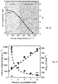
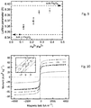
- the solid lines delimiting the shaded region are calculated curves from equation 14 for ideal magnetite and maghemite, as annotated.
- the arrows show the effect on the saturation magnetization of the initial precursor concentration, and the charge-to-mol ratio.
- a routine GDEx experiment performed for the synthesis of these particles includes the elements shown in figure 1 .
- the electrochemical cell itself contains 3 chambers.
- the leftmost chamber faces a hydrophobic layer of the GD electrode, through which an incoming gas flows at fixed rate, with a set overpressure.
- the catholyte and anolyte flow from, and to 3-necked glass bottles serving as reservoirs through the respective cell compartment.
- the anolyte and catholyte in the cell are separated by a Zirfon® separator.
- the anode is a platinum disk. Both electrodes and the separator have a projected cross section of 10 cm 2 .
- the circuit is completed with a potentiostat and a Ag/AgCl reference electrode is placed via a Luggin capillary close to the GD electrode.
- Iron oxide nanoparticles were synthesized using concentrations of FeCl 2 ranging from 1, 3, 5 and 7 mM to 9 mM. Use was made of. 0.25, 0.75, 1.25, 1.75 and 2.25 mmol of FeCl2 ⁇ 4H2O (99%,Sigma-Aldrich), dissolved in 250 mL of distilled water, respectively together with 7.5 g of NaCl. The anolyte solution consisted of the70 same NaCl electrolyte without the Fe precursor salt.
- the pH of every solution was adjusted to 2.7 with 30% HCl.
- the solutions were cycled through the GDEx cell with a peristatic pump (530, Watson-72 Marlow) at 42 mL min-1. Air was pumped through the gas compartment of the cell at 100 mL/min with an overpressure of 20 mbar. The solution and gas were flushed through the cell for 30 min prior to each experiment (without electrode polarization).
- a potential of -350 mV (vs. Ag/AgCl) was applied to the GDE using a Bio-Logic VMP3 potentiostat. At regular intervals, 1 mL samples of the catholyte solution were taken, centrifuged and filtered with a 0.3 ⁇ m filter.
- the filtered solutions were analyzed with an inductive coupled plasma-mass spectrometer (ICP-MS) for the iron content.
- ICP-MS inductive coupled plasma-mass spectrometer
- the pH of the catholyte was continuously monitored until a value of 11.5 was reached, at which point the polarization was stopped and the suspension of particles was collected.
- the suspension of particles as-synthesized was centrifuged 3at 12000 rpm for 15 minutes 3 times, using a Thermo Scientific Sorvall RC 6+ centrifuge. Each time, the particles were re-dispersed with deionized (DI) water to clean any remaining NaCl and NaOH. After the conductivity of the dispersions reached a stable83 value between centrifuge rounds, the samples are centrifuged one last time and dried under a nitrogen atmosphere for further characterization.
- DI deionized
- the dry samples were analyzed by powder x-ray diffraction (XRD) in a Pan Alytical X' Pert Pro diffractometer using a Cu K ⁇ radiation source. Samples were crushed and placed in standard monocrystal sample holders. Measurements were performed with a spinner at 40 mA-40 kV spending 4 s per step with a step size of 0.04° 2 ⁇ in the 10-110° 2 ⁇ range. Rietvield refinements were performed in all samples to fit the profiles and extract the lattice parameters from the data using HighScore Plus software. Crystallite sizes were calculated using the Scherrer equation.
- Additional XRD characterization was performed in a PanAlytical Empyrean diffractometer using Co K ⁇ radiation with 40 mA-45 kV and a finer step size of 0.013° 2 ⁇ in the same scan range.
- the small step size and the Co source were chosen to probe the possibility of multi-phase detection by95 observing peak splitting at wide angles.
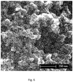
- Micrographs of the dry samples were taken with a FEI Nova NanoSEM 450. Images presented were taken with secondary electrons and an acceleration voltage of 5.00 kV.
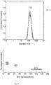
- a Zetasizer Nano ZS (Malvern) was used to perform Dynamic Light Scattering (DLS) measurements on colloidal suspensions. After synthesizing the samples, and removing excess salt and hydroxide by centrifugation as explained previously, but before drying, 1 mL aliquots of the products were collected for DLS analysis. The concentrated samples were diluted in DI water to the range of 0.1 mg/ml of particles to water. The pH was adjusted to 10 with a 1 M/l solution of NaOH. A refractive index of 2.5 and an extinction coefficient of 0.13 were used for DLS measurements.
- FTIR Fourier Transform Infrared Spectroscopy
- the solid samples were measured in a Nexus® Spectrometer (Thermo Nicolet).
- the powders were mounted on a stage with a diamond ATR for direct sampling of the materials.
- Permanganate titrations were performed to measure the concentration of ferrous ions in solution as the synthesis process occurs. Samples from 1 to 5 ml were taken from the catholyte reservoir at various points during the synthesis. The samples were mixed with 1 ml concentrated HCl to dissolve any present particles. The mixture was diluted by adding 70 ml of distilled water. A 10 mM solution of NaMnO 4 was prepared and used to titrate the iron samples.
- the charge consumed (shown in Figure 2b ) to carry the synthesis is the same, and depends only on the pH ranges, and the metal concentration.
- Current densities (80 A m -2 ) throughout the synthesis were constant for all precursor concentrations, as well as for the blank electrolyte solution.
- Chronoamperometric data from experiments concerning each studied concentration can be found in SI Figure 7 .
- the volume charge density ( Q t , C L -1 ) consumed by the synthesis can then be modelled by equation 7 below, as shown in Figure 1 .
- the diffractograms in figure 3 show similar characteristics across all samples.
- the patterns are face centered cubic (fcc) inverse spinels of Fd3m space group pointing to single phase, crystalline, Fe3O4. Nonetheless, total or partial lack of Fe 2+ may be compensated by iron vacancies to form the structurally-similar maghemite ( ⁇ -Fe 2 O 3 ).
- FTIR spectra shown in Figure 4 , reveal expected features for magnetite. All 5 samples exhibit the same absorption peak at 550 cm-1, indexed to vibrations from Fe-O bonds. Samples synthesized from 3 mM Fe 2+ solutions and under, especially from 1 mM, show O-H stretching vibrations ( ⁇ 3410 cm -1 ) and deformed vibrations ( ⁇ 1630 cm -1 ). 15 The noise around 2200 cm -1 in all the traces arises from atmospheric CO 2 . Samples synthesized from 3 mM Fe 2+ solutions, and specially from 1 mM, show O-H stretching vibrations ( ⁇ 3410 cm -1 )135 and deformed vibrations ( ⁇ 1630 cm -1 ).
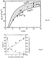
- Crystallite sizes were calculated from the diffractograms using the Scherrer equation, the results are shown in figure in Figure 5b .
- Several techniques were employed to determine the size of the particles in different manners. The naked particles were transferred and analyzed in the dry state by SEM and XRD, while size distribution in dispersions was measured by DLS and spICP-MS represented in figure 5b . Due to the nature of the techniques, crystallites, particles and aggregates can be studied to obtain a full characterization of the size regimes.
- the charge needed to precipitate the metals is only part of the total contribution to the overall charge spent, as part of the generated hydroxides are consumed to increase the pH.
- Stoichiometric magnetite is composed of a face-centered cubic oxygen sub-lattice with Fe 3+ ions in tetrahedral sites, and Fe 3+ and Fe 2+ in octahedral ones. Over-oxidation can be expressed as ferrous vacancies in the lattice. Exposure of Fe 3 O 4 to oxygen can create such vacancies by surface oxidation and subsequent inward diffusion of defect. Structurally, magnetite can be written as (Fe 3+ ) tet (Fe 2+ Fe 3+ ) oct O 4 with subscripts 'tet' and 'oct' referring to tetrahedral and octahedral sites respectively.
- Table 1 Summary of measured properties. Average particle sizes are extracted from SEM, crystallite sizes and lattice parameters from XRD data and Rietvield refinements, saturation magnetization (M s ) and coercivity (H e ) from VSM data.
- Precursor Crystallite Particle size Lattice M s H c concentration (mM) size (nm) SEM (nm) parameter ( ⁇ ) (emu g -1 ) (Oe). Fe conc. (mM) Crystallite size (nm) Lattice parameter ( ⁇ ) M s (A m 2 kg -1 ) H c (kA m - 1 ) 1 5 8.34 23.6 1.5 3 10 8.35 50.5 1.2 5 11 8.36 52.3 1.0 7 16 8.38 62.2 1.8 9 18 8.39 73.0 3.9
- the magnetization curves are shown in Figure 10 for the 5 precursor concentrations mentioned above.
- the curves show little hysteresis, the samples have small coercivity.
- the sample with the largest crystallite size (18 nm) exhibits also the largest coercivity of 3.9 kA m -1.
- the smallest coercivity (1.0 kA m -1 ) is seen with samples synthesized from 5 mM of Fe 2+ and with a 11 nm crystallite size.
- Table 1 contains the full results.
- the maximum saturation magnetization is observed from the largest crystallites, ⁇ 80% that of bulk magnetite (taken as 92 Am 2 kg -1 ). M s is correlated to size, decreasing sizes commonly show decreasing magnetization.
Landscapes
- Chemical & Material Sciences (AREA)
- Engineering & Computer Science (AREA)
- Chemical Kinetics & Catalysis (AREA)
- Electrochemistry (AREA)
- Materials Engineering (AREA)
- Metallurgy (AREA)
- Organic Chemistry (AREA)
- Inorganic Chemistry (AREA)
- Compounds Of Iron (AREA)
Abstract
Description
- The present invention relates to an electrochemical process for producing magnetic iron oxide nanoparticles with a desired saturation magnetization, from a solution of at least one soluble Fen+precursor salt in a solvent according to the preamble of the first claim.
- As nanomaterials make their way to the forefront of a variety of applications, synthesis, characterization, and functionality of magnetic iron oxide nanoparticles (IONPs) have been the focus of significant research. With good chemical stability, IONPs are one of the benchmark nanomaterials for a diverse range of practical applications ( Rochelle M Cornell and Udo Schwertmann, Advanced drug delivery reviews, 58(14):1471-1504, 250, 2006 ). They show encouraging potential in diagnostics, biosensing, energy and data storage, and as contrast agents for functional Magnetic Resonance Imaging (fMRI), besides other emerging uses ( Sophie Laurent, Delphine Forge, Marc Port, Alain Roch, Caroline Robic, Luce Vander Elst, and Robert N, Chemical reviews, 108(6):2064-2110, 2008 ).
- Generally, the properties and potential applications of iron oxide nanoparticles are determined by their physicochemical characteristics. Therefore, size, dispersity, composition, and structure, are amongst the aspects that must be precisely tailored for each specific use.
- Among the commonly-found iron oxides, of main interest is Fe3O4 (magnetite). Fe3O4 is the iron oxide that exhibits the largest saturation magnetization (92 A m2 kg-1) and a high Curie temperature (840 K) in the bulk ( Rochelle M Cornell and Udo Schwertmann, The iron oxides: structure, properties, reactions, occurrences and uses. John Wiley & Sons, 2003 ). When the particle size becomes smaller than the magnetic domain size (approximately 25 nm-30 nm), magnetite transitions from ferrimagnetic to superparamagnetic ( Kannan M Krishnan, IEEE transactions on magnetics, 46(7):2523-2558, 2010 ).
- Iron oxide nanoparticles can exhibit close to bulk magnetization at relatively large sizes of around or above 20 nm. Further below the ferrimagnetic-superparamagnetic transition size, the saturation magnetization decreases ( Sophie Laurent, Delphine Forge, Marc Port, Alain Roch, Caroline Robic, Luce Vander Elst, and Robert N Muller, Chemical reviews, 108(6):2064-2110, 2008 ). IONPs, as opposed to larger ferrimagnetic particles, are better suited for preparing stable dispersions, a key feature for various applications. Of crucial importance in the optimization of IONP synthesis is the ability to control the phase composition of the IONP, and the ability to synthesise ∼20 nm particles with a narrow particle size distribution, i.e. a dispersity index of smaller than 0.2. measured according to DLS. By controlling the size of the particles, optimal magnetization may be achieved, while fine control over the phase composition (Fe3O4 vs. γ-Fe2O3) may enable the formulation of precise structure-property relations ( Yury V Kolenko, et. alThe Journal of Physical Chemistry C, 118(16): 8691-8701, 2014 ).
- Numerous synthesis techniques exist for the synthesis or IONPs and they vary in nature and focus. Sol-gel, coprecipitation, microemulsion, hydrothermal, electrochemical, thermolysis of precursors, and spray pyrolysis, are the most often used processes ( Yury V Kolenko, et al., The Journal of Physical Chemistry C, 118(16): 8691-8701, 2014 ; Maria Starowicz et al., Journal of Nanoparticle Research, 13(12):7167-7176, 2011 ; Dipak Maity, et al., Journal of Magnetism and Magnetic Materials, 321(9):1256-1259, 2009 ). All these techniques lead to a different degree of control over the aforementioned properties, like the phase composition of the IONPs and the average particle size and particle size distribution of the particles. For many applications, the chemical (stoichiometric) coprecipitation of mixed iron salts (i.e., Fe3+ and Fe2+) is the most commonly found synthesis route ( Sophie Laurentet al., Chemical reviews, 108(6):2064-2110, 2008 ).
-
US8940179 discloses a method for preparing magnetite nanoparticles from low-grade iron ore, comprising the steps of : - (1) adding iron ore powder to an acidic solution and stirring the mixture to obtain iron ore leachate;
- (2) centrifuging the iron ore leachate and separating and discharging residual powder to obtain a supernatant;
- (3) adding an oxidant to the supernatant to oxidize all Fe2+ ions to Fe3+ ions, adding a solvent extractant thereto to form an iron-solvent extractant complex, separating the iron-solvent extractant complex from the solution, and adding distilled water to the separated iron-solvent extractant complex to obtain an aqueous solution containing Fe3+ ions;
- (4) preparing an aqueous solution containing Fe2+ ions by adding a reducing agent to a volume of one-third to one-half of the aqueous solution containing Fe3+ ions obtained in step (3) such that Fe3+ ions are reduced to Fe2+ ions, and preparing an iron salt mixed solution by adding the aqueous solution containing Fe2+ ions to the remaining aqueous solution containing Fe3+ ions; and
- (5) adding the iron salt mixed solution to an alkaline aqueous solution to prepare magnetite nanoparticles.
- The method disclosed in
US8940179 however presents the disadvantage that one single reaction product is produced, i.e., magnetite with a defined set of immovable characteristics. Moreover, the method does not permit producing other forms of iron oxides, it does not permit controlling the stoichiometry, and other relevant physicochemical properties of the iron oxides, such as the precise chemical composition, the oxidation state of the iron in the oxides produced, the crystallite size of the nanoparticles, the lattice parameters of the iron oxide crystals, the concentration of defects (i.e., vacancies), and the saturation magnetization. -
US20130126394A1 discloses a method of preparing magnetic iron oxide nanoparticles, comprising the steps of: - i) reacting a water-soluble ferrous salt with a water-soluble ferric salt in a mole ratio of 1:2 in the presence of a base and a citrate to give an iron oxide particle surface-coated with the citrate (c-MNP);
- ii) reacting the c-MNP obtained in step (i) with a thiophilic compound to give a thiophilic compound-bounded iron oxide particle surface-coated with the citrate (thiophilic-c-MNP); and
- iii) modifying the thiophilic-c-MNP obtained in step (ii) using a surfactant for phase transfer of the thiophilic-c-MNP from aqueous phase to organic phase.
- The method disclosed in
US20130126394A1 however relies on the co-precipitation reaction of specific iron salts, in particular water soluble ferric- and ferrous- salts, in a specific molar ratio of 1:2. The magnetic iron oxide particles produced have an average particle diameter of 1000-1400 nm, and can therefore not be formally classified as nanoparticles which are typically defined as particles with an average particle size of below 100 nm. -
US20080003159A1 discloses a method for producing single component magnetic or metal oxide nanoparticles, which comprises: - (1) adding a magnetic or metal precursor to a surfactant or a high boiling solvent containing the surfactant to produce a mixed solution,
- (2) heating the mixed solution to 50-600 °C, preferably 240-400 °C, to decompose the magnetic or metal precursor by heating and form the magnetic or metal oxide nanoparticles, and
- (3) separating the magnetic or metal oxide nanoparticles. Suitable precursors include metal nitrate-based compounds, metal sulfate-, metal fluoroacetoacetate-, metal halide-, metal perchlorate-, metal sulfamate, metal stearate-based compounds and organometallic compounds.
- The surfactant is used to stabilize the magnetic or metal oxide nanoparticles, and is added in an amount of 8-50 times that of the precursor. The solvent is added in an amount of 5-40 times that of the precursor. The size of the magnetic oxide nanoparticle can be controlled by the concentration of the magnetic precursor, and the higher concentration of the precursor the size of the magnetic oxide nanoparticle. The diameter of the metal oxide nanoparticles can be controlled by the nature and concentration of the surfactant. Although the method disclosed in
US20080003159A1 does not require the use of an oxidizing or a reducing agent to mass-produce uniform magnetic or metal oxide nanoparticles having desired particle sizes, it is carried out at high temperatures and the particle size is controlled by the surfactant. - Although various processes have been developed for the production of magnetic iron oxide nanoparticles from iron oxide precursors, none of the prior art processes permits at the same time controlling the particle size, crystallite size, lattice parameter, concentration of defects (i.e., vacancies), and the stoichiometry of the magnetic iron oxide nanoparticles, in order to obtain iron oxide particles with a precisely-controlled and predictable degree of magnetization.
- The present invention therefore seeks to provide a process for the production of magnetic iron oxide nanoparticles with a desired degree of magnetization, which permits to control at the same time the particle size, the stoichiometry and Fe speciation of the iron oxide nanoparticles obtained from that process.
- This is achieved according to the present invention with a process which shows the technical features of the characterizing portion of the first claim.
- Thereto, the present invention relates to an electrochemical process for producing from a solution of at least one soluble Fen+ precursor salt in a solvent, magnetic iron oxide nanoparticles with a desired saturation magnetization, the process comprising the steps of
- supplying the solution containing the at least one Fen+ precursor salt to a cathode compartment of an electrochemical cell, containing a catholyte and equipped with a cathode comprising a gas diffusion electrode provided with a porous electrochemically active material,
- supplying an O2-containing oxidant gas to the gas diffusion electrode, wherein the O2 mole fraction in the oxidant gas ranges between 0.10 and 1.0,
- subjecting the cathode to an electrochemical potential which is below the thermodynamic limits of O2 reduction at a pH prevailing in the cathode compartment,
- rendering a current between 10 and 1000 Am-2 to cause reduction of the O2 contained in the oxidant gas, to one or more of the corresponding peroxide, OH-, ionic and/or radical reactive species to oxidize the Fen+ ion into one or more magnetic iron oxides Fe2+xO3+x, with 0 < x < 1, with the Fe ion in an oxidation state that is higher than n+,
- and isolating nanoparticles of the one or more magnetic iron oxides.
- The present invention provides a one step, process for converting a dissolved Fen+ precursor salt into nanoparticles of one or more magnetic iron oxides with a desired or defined stoichiometry, which may be carried out in one single reactor. The precursor salt may contain exclusively Fe ions in the divalent state as Fe2+, but the precursor salt may also comprise a mixture of iron salts with Fe ions in different oxidation states. Usually these oxidation states will be higher than 2+. However, the skilled person can recognize that the use of an elemental Fe0 sacrificial anode is possible for the provision of such oxidized states (i.e., by anodic dissolution).
- The inventors have observed that the process of the present invention permits producing from an iron salt, one or more iron oxide reaction products which are magnetic and have a desired degree of magnetization, and which have a desired, tailored stoichiometry. The present invention in particular permits tailoring the oxidation state of the Fe atoms (i.e., Fe speciation) of which the magnetic iron oxide is composed, as well as the concentration of each Fe-atom of a certain oxidation state within the iron oxide reaction product. This means that the process of this invention permits producing iron oxides which contain a desired amount of one or more iron atoms or a mixture of iron atoms in a desired oxidation state. As a result, the process of this invention permits producing iron oxides with magnetic properties, with a desired degree of magnetization.
- The present invention additionally presents the advantage that the process permits to additionally control the particle size, crystallite size, lattice parameter and concentration of vacancies in the magnetic iron oxide nanoparticles.
- In particular it has been observed that by adapting the O2 partial pressure and the electrochemical potential applied to the cathode, the iron oxides produced may range from maghemite to magnetite, i.e., iron oxides may be obtained with a stoichiometric composition ranging from Fe(III)2.67O4 to Fe(II)Fe(III)2O4, in particular from Fe(II)0.22Fe(III)2.52O4 to Fe(II)0.76Fe(III)2.16O4.
- It has further been observed that by adapting the O2 mole fraction in the gas-phase, the electrochemical potential applied to the cathode, and the initial concentration of the iron precursor salt(s), iron oxides may be produced with a desired saturation magnetization, in particular the saturation magnetization may be tailored to range from 15 to 100 Am2 kg-1, preferably from 20 to 92 Am2 kg-1, more preferably between 23 and 73 Am2 kg-1.
- The method of the present invention also permits producing solid powders or dispersions of the naked or capped magnetic iron oxides. The reaction product may therefore be used either the way it has been produced, it may be freed of water and dried, shielding agents may be added to shield the oxides from the solution (or its remainders), for example to counteract particle agglomeration and growth or to achieve a certain function at the particle surface.
- The inventors have observed that the selected O2 mole fraction range employed in the process of this invention ensures that the reactants needed to achieve oxidation of the Fen+ into iron oxide with a higher oxidation state and saturation magnetization, in particular OH- and H2O2, are formed in situ in the electrolyte (catholyte). The inventors confirmed that the reduction of the O2 containing oxidant gas at the cathode gives rise to the formation of at least OH- and peroxide species or intermediates, which are needed to obtain iron oxides with a sufficiently high oxidation state, so that the magnetic Fe2O3 oxide may be formed.
- Lower O2 mole fractions, in particular below 0.1 have been found to limit current transfer in the catholyte and to promote formation of intermediate species that do not favor the formation of iron oxides with a desired saturation magnetization, but rather promote formation of a.o., FeO(OH).
- The inventors have also observed that electrochemical potentials leading to current densities below 10 Am-2 slow down the production of the oxidizing agents that lead to the oxidation reaction and promote formation of iron oxide particles above nanoparticle size ranges. With this low charge applied, the time needed to obtain the desired forms of iron oxide would significantly increase to values that are no longer economically feasible, and mainly lead to the formation of under-oxidized species, a.o., FeO(OH) species. When applying larger currents, i.e., above 1000 Am2, the risk increases to the formation of iron oxides which do not show the desired saturation magnetization, like FeOOH and Fe2O3. Thus, the time during which current is applied should be carefully selected to limit oxidation to a desired extent. It seems therefore that by adapting the charge that is applied to the reaction medium, the rate with which oxidants produced in the reaction, and therefore the rate with which these further react with the iron ions in the reaction mixture is controlled. It further seems that the O2 mole fraction range and the current density (and hence electrochemical potential) applied to the cathode surface for a given time, co-operate to form the desired reactive species which support the conversion of an iron oxide into nanoparticles of iron oxide with magnetic properties.
- The skilled person will be capable of selecting the time during which the current is applied, i.e., of selecting the charge applied, taking into account the other circumstances prevailing in the reaction mixture, the nature of the iron oxide to be produced and the saturation magnetization desired.
- The electrochemical potential to which the gas-diffusion cathode is subjected, is a reducing potential relative to a reference electrode, preferably below the thermodynamic pH-potential equilibrium region of stability of the O2 oxidant gas in the reaction medium preferably a reducing potential relative to a reference electrode, which is below the thermodynamic pH potential equilibrium region of stability of the oxidant gas O2 in water. As will be clear from the detailed description of the invention below, the pH may change in the course of the reaction, which may involve the need to adapt the electrochemical potential in the course of the reaction so that it remains below the thermodynamic limits of O2 reduction at a pH prevailing in the cathode compartment. Where water is used as the solvent or one of the solvents of the reaction medium, the electrochemical potential is preferably selected such that it is below the region of thermodynamic stability of water and outside of the region of thermodynamic stability of hydrogen. This way the risk to the occurrence of water electrolysis to form hydrogen may be minimized.
- The reactions considered to intervene in the process of the present invention are assumed to be as follows :
Fe2+(aq) + H2O2(aq) → Fe3+(aq) + OH-(aq) + OH·(aq) (1)
Fe2+(aq) + OH·(aq) → Fe3+(aq) + OH-(aq) (2)
Fe3+(aq) + H2O2(aq) → Fe2+(aq) + HO·2(aq) + H+(aq) (3)
OH(aq) + H2O2(aq) → HO2(aq) + H2O(l) (4)
The charge needed to precipitate the metal oxides is only part of the total contribution to the overall charge spent, as part of the hydroxides generated are consumed to increase the pH. Regardless of the mechanism for oxygen reduction at the electrode (4- vs 2-electron process) the same ratio of 1 mol of hydroxide produced (or protons consumed) per electron remains (seeReactions
O2 +4e-+ 2H2O(l) → 4OH-(aq) (5)
O2(g)+2e-+ 2H2O → HO2(aq) + 2OH-(aq) (6)
The presence of reactive oxygen species, such as peroxide produced at the surface of the gas diffusion electrode, provides the conditions for oxidizing ferrous ions, as is described byReaction 1. Where the reaction mixture contains a mixture of Fe3+ and Fe2+ the formation of magnetite Tet [Fe3+] Oct [Fe2+ 1-3δFe3+ 1+2δ□δ]O4 (wherein δ refers to the content of vacancies in the structure)
is enabled, as described byreaction 8 below :
Fe2+(aq) + 2Fe3+(aq) + 8OH-(aq) → Fe3O4(s) + 4H2O(l) (8)
A common mechanism during co-precipitation processes involves the formation of goethite FeIIIOOH as represented byreaction 9, followed by a topotactic transformation to magnetite if in the presence of ferrous ions as shown in reaction 10 :
Fe3+(aq) + 3OH-(aq) → FeOOH(s) + H2O(l) (9)
- Fe2+(aq) + 2FeOOH + 2OH-(aq) → Fe3O4(s) + 2H2O (1) (10) From the above it becomes clear that the degree of iron oxidation plays a crucial role in the precipitation process. By controlling the charge applied to the reaction medium, the rate with which oxidants are produced may be controlled, and the nature and amount of oxidized iron species may be controlled.
- In the process of this invention, preferably the solution of at least one soluble Fen+ precursor salt in a solvent is a solution comprising at least one soluble Fe2+ precursor salt. According to another preferred embodiment, the at least one soluble Fen+ precursor salt contains a mixture of Fe3+ and Fe2+ salts. In an embodiment, the presence of a single Fen+ precursor in the catholyte is preferred, as it facilitates controlling the reactions that take place and therefore the product formed, and makes the process more economic.
- In the process of this invention preferably, the concentration of the at least one soluble Fen+ precursor salt in the reaction medium is below 20.0 mM, preferably below 10.0 mM.. Selection of an appropriate concentration in the afore-mentioned range, will permit to tailor both the size of the iron oxide crystals and the iron oxide particles formed. In particular it has been observed that an increasing concentration of the soluble Fen+ precursor salt in the reaction medium favours formation of larger crystals. Besides this, selection of an appropriate concentration within the afore-mentioned range permits to tailor the crystallite size in a range between 5 and 20 nm, preferably between 5.5 and 18.5 nm. Furthermore, selection of an appropriate concentration permits to tailor the particle size of the magnetic iron oxide in a range between 20 and 75 nm, preferably between 20 and 55 nm, more preferably between 35 and 55 nm.
- More preferably, the concentration of the at least one soluble Fen+ precursor salt in the solution ranges between 0.001 mM and 20.0 mM, preferably between 0.01 mM and 20.0 mM, more preferably between 0.1 mM and 20.0 mM, most preferably between 1.0 and 20.0 mM. Concentrations below 1.0 mM generally lead to low yields of magnetic iron oxides, whereas with concentrations above 20 mM the risk increases to crystal aggregation and the formation of larger iron oxide particles of micro meter size which risk to clog the electrochemical cell and have a limited stability in relation to particle size. The saturation magnetic hysteresis has been found to depend on the crystallite and particle size, as well as on the lattice parameter, and the concentration of vacancies, which are in turn controlled by the iron precursor concentration.
- More in particular, by varying the concentration of the soluble iron precursor salt as described above, additionally the chemical composition, stoichiometry, oxidation state, and lattice parameter of the iron oxide crystallites may be controlled by varying the concentration of the water soluble iron precursor salt in the aqueous solution between 1 and 10 mM. The fact that the magnetic iron oxide nanoparticles may be produced from such diluted solutions is an advantage in particular as it allows for fast nucleation and limited risk to particle agglomeration.
- The concentration of the soluble Fen+ precursor salt in the catholyte may for example be varied by varying the rate with which the soluble Fen+ precursor containing catholyte is supplied to the cathode. Such variation will in particular be done when variation of the crystal size of the reaction product is envisaged, since varying the concentration of the Fen+ precursor salt permits varying the crystal size of the reaction product, as well as the particle size. The inventors have observed that iron oxide particles with a desired stoichiometry and particle size may be achieved by operating the process of this invention with a catholyte supply rate that ranges between 5.0 and 150.0 ml/min, preferably between 5.0 and 100.0 ml/min, most preferably between 5.0 and 50 ml/min. Higher the supply rates generally lead to magnetic iron oxide particles with a smaller particle size, whereas lower supply rates lead to magnetic iron oxide particles with a larger particle size. Thus by varying the catholyte supply rate, the average particle size of the iron oxide particles may be tuned, as well as their effective surface area.
- In the process of this invention the pH of the catholyte is preferably adjusted to a value which ranges between 2.0 and 6.0, preferably between 2.0 and 5.0, more preferably between 2.5 and 3.5 to achieve a sufficiently high yield of precipitated iron oxide particles. Within the indicated pH ranges, the pH is smaller than the pH range within which a relative predominance exists of the iron precursor in the ionic form. Within the indicated pH ranges, the pH is namely smaller than the pKa of the Fen+ precursor salt.
- The method of this invention may be carried out in aqueous solution, which only contains water as the liquid phase or solvent. The method of this invention may however also be carried out in a liquid phase or solvent which contains a mixture of water and one or more organic solvents, or in an organic solvent or a mixture of two or more organic solvents. The process of this invention may be carried out in water or a polar organic solvent for the at least one Fen+ oxide or in an apolar organic solvent, or a mixture of two or more of the afore-mentioned solvents.
- The skilled person will be capable of selecting the most appropriate solvent, taking into account a.o. the particle size to be achieved and the envisaged application of the iron oxide. An appropriate selection of the solvent will permit controlling the dimensions of the magnetic iron oxide particles. The inventors have namely observed that the use of water as the solvent or a polar organic solvent favours crystallite and particle aggregation and may give rise to the formation of particles with a larger average particle size. Therefore, such solvents will generally be used when the formation of larger iron oxide particles is envisaged. The use of an apolar organic solvent on the other hand counteracts particle aggregation and may give rise to the formation of particles with a smaller average crystal and particle size often smaller than 20 nm and preferably smaller than 10 nm). Therefore, if the formation of particles with a small average crystal size and a small particle size of maximum 20 nm and preferably below 10 nm is envisaged, the use of an apolar organic solvent may be preferred. The nature of the solvent may further be varied taking into account the envisaged application, for example in case biocompatibility is desired. In this case water will still be the preferred solvent.
- The process of this invention is suitable for use with a wide variety of iron precursor salts. The nature of the soluble iron precursor salt may be varied and may be for example be selected from the group of a chloride, nitrate, sulfate, phosphate, perchlorate or a mixture comprising two or more of the afore-mentioned compounds. It shall however be clear that other precursor salts known to the skilled person may be used as well. It has been observed that different geometries of the nanoparticles may be obtained (e.g., triangular, spherical, etc.) by varying the nature of the soluble iron precursor salt.
- The oxidant gas used in the process of this invention may consist of pure O2 or a mixture of O2 with one or more other gases, which preferably are inert to the electrochemical reaction, in particular N2, or a noble gas, more particularly Ar. When using a mixture of gases (e.g., O2 and N2) the skilled person will be capable of adjusting the partial pressure of the oxidant gas in such a way that it is sufficiently high to enable its electrochemical reduction, as low oxygen partial pressures may limit the extent of reaction due to production of O containing species with low reactivity and/or give rise to the formation of too small crystals and too small nanoparticles.
- The rate with which the O2 containing oxidant gas is supplied to the cathode is preferably variable. In a preferred embodiment a supply rate with which the oxidant gas is supplied to the gas diffusion electrode ranges between 5.0 and 300.0 ml/min, preferably between 5.0 and 250.0 ml/min, more preferably between 5.0 and 150.0 ml/min. In a further preferred embodiment, a partial pressure of the oxidant gas that is supplied to the gas diffusion electrode is variable. Thereby, preferably the O2 mole fraction in the O2 containing oxidant gas is at least 0.15, preferably at least 0.20, more preferably at least 0.21. Lower partial pressures are expected to result in an insufficient production of reactive oxygen species such as peroxide, and to favour formation of less reactive species such as OH-, etc. In a further preferred embodiment, the O2 partial pressure in the oxidant gas ranges between 0.20 and 1.0.
- In the process of this invention, usually the working potential of the cathode is set at a value between -50.0 and -750 mV vs. Ag/AgCl, preferably at a value between -100.0 and -650 mV, more preferably between -250 and -500 mV, as within these ranges iron oxides with the desired stoichiometry, with iron in a desired oxidation state for iron oxides with magnetic properties, may be obtained. It has been observed that by varying the electric or electrochemical potential at the cathode, the oxidation state of the Fe ions in the iron oxide or iron oxides formed, may be controlled, and iron oxide may be formed which vary from maghemite to magnetite. Working potentials more negative than -750 mV are generally not preferred as they support formation of hydrogen, reducing the efficiency of the targeted reactions.
- Preferably, the process of this invention is carried out in a catholyte with an ionic conductivity that is sufficiently high, to ensure that the electrochemical conversion proceeds sufficiently fast to permit keeping the average size of the iron oxide crystals small and limiting crystal aggregation to form larger particles within a desired extent. To that end, preferably use is made of a catholyte with and an ionic conductivity of at least 1.0 mS/cm, preferably at least 10 mS/cm. This conductivity may be achieved by the addition of a supporting electrolyte, such as but not limited to, NaCl.
- If needed, unwanted variations in the conductivity of the reaction medium may be compensated by supplying additional electrolyte or by incorporating into the catholyte a binary electrolyte. This may be of particular importance when the process of this invention is operated in a continuous manner, and continuous supply of metal and/or metalloid ions to be recovered takes place. By the presence of the binary electrolyte, the electrolytic conductivity may be increased to at least 5, preferably to at least 10, more preferably between 20 and 80 and even more preferably between 20 and 50 mS.cm-1 and thereby the risk to a varying conductivity as a result of the removal of the reactant iron precursor salt due to its oxidation may be minimised.
- If so desired, to keep the pH within the desired limits as described above, an amount of a weak protonic electrolyte may be supplied to the catholyte. The inventors have found that the oxidation rate may thereby be accelerated. The weak protonic electrolyte is assumed to act as a catalyst or co-catalyst in the formation of reactive peroxide and/or radical species from the oxidant gas at the cathode, and to accelerate the oxidation of the iron ion of the soluble iron precursor salt. Addition of the weak protonic electrolyte may not only increase the conductivity of the catholyte, but that it may also increase the current density over the cathode. Moreover, the presence of the weak protonic electrolyte has the effect that variations in the pH of the catholyte in the course of the oxidation reaction may be reduced to a minimum. This contributes to minimizing the risk to the occurrence of unwanted side reactions which would lead to the formation of nonmagnetic iron oxides. In practice, the amount of weak protonic electrolyte may vary within wide ranges but is preferably not less than a 10 mM solution and preferably not more than a 1.5 M solution, more preferably the concentration of the weak electrolyte varies between 10 and 500 mM, most preferably around 100 mM.
- The weak protonic electrolyte will usually be a weak protonic acid. A weak protonic acid is a protonic acid which only partially dissociates in water :

- Preferred weak protonic acids for use with the present invention have a pKa of between 2.0 and 6.0, preferably between 3.0 and 5.0, more preferably about 3.0. Examples of weak protonic acids suitable for use with the present invention include those selected from the group of weak organic and weak inorganic acids, in particular acetic acid, citric acid, oxalic acid, lactic acid, gluconic acid, ascorbic acid, formic acid, glycolic acid, potassium monohydrogen phosphate, potassium dihydrogen phosphate, ammonium chloride, boric acid, sodium hydrogen sulphate, sodium hydrogen carbonate, ammonium chloride, and mixtures of two or more hereof. The weak protonic acid may be a monoprotonic acid, but preferably is a polyprotonic acid. Particularly preferred weak protonic acids are those having a pKa which is at least one unit higher than the pH of the catholyte at the initial processing conditions.
- The electrolyte may further contain a surfactant, capping agent or stabilizer additive.
- The electrochemically active material of the gas diffusion electrode which forms part of the cathode used in the process of this invention preferably comprises an active surface having a plurality of active sites with a weak protonic acid functionality, i.e. active sites which only partially dissociate in water. Various electrochemically active materials may be used to achieve this. Preferred are those materials which have a surface comprising protonic acid functional groups. Particularly preferred are those materials which comprise electrically conductive particles of carbonaceous origin, more preferably those comprising electrically conductive particles of carbonaceous origin with a catalytically active surface comprising a plurality of protonic acid groups. It is believed that the protonic acidic functional groups present on the catalytically active surface, in particular acidic functional groups of the type R- H, may partly dissociate at a corresponding pH. The inventors also believe that the thus dissociated surface groups have a high oxygen affinity and thus intervene in the oxidation of the metal ion or the metalloid ion.
- As electrochemically active material, a wide variety of conductive materials may be used, but preferred are porous materials, in particular those which contain weak protonic acid functional groups. Examples of such materials are well known to the skilled person and include porous metals and metalloids, for example porous nickel or copper, porous carbon based materials, porous ion exchange resins, carbon aerogels, silicon, conductive polymers, conductive foams or conductive gels, among others. The use of a porous carbon based material as or in the electrochemically active surface is preferred, because of its catalytic activity in combination with a reasonable cost and abundant availability in comparison to other materials. Examples of suitable materials include graphite, carbon nanotubes, graphene, carbon black, acetylene black, activated carbon or synthetic carbons such as vulcan. Other electrochemically active materials suitable for use with this invention include carbonaceous materials the surface of which has been chemically modified to adapt its catalytic activity and compatibility with the reaction medium. Without wanting to be bound by this theory, it is believed that the presence of oxygen-containing functional groups support the oxidation reaction. Particularly preferred carbon materials have a surface with quinone-type functional groups.
- Suitable porous material for use as the electrochemically active layer of the gas diffusion electrode preferably have a high specific surface area as measured by the BET method described in ASTM D5665, in particular a BET surface area of at least 50 m2/g, preferably at least 100 m2/g, more preferably at least 200 m2/g, most preferably at least 400 or 500 m2/g, but those having a surface area larger than 750 or 1000 m2/g or even more may be particularly preferred. Porous materials particularly suitable for use as the electrochemically active layer include carbonaceous particles selected from the group of graphite, carbon nanotubes, graphene, carbon black, activated carbon or synthetic carbons. Preferred conductive carbonaceous particles have a BET surface area of at least 50 m2/g, preferably at least 100 m2/g, more preferably at least 200 or 250 m2/g, most preferably at least 400 or 500 m2/g, but those having a surface area larger than 750 or 1000 m2/g or even more may be particularly preferred.
- Suitable porous material for use as the electrochemically active layer preferably form a continuous layer on the cathode. Thereto, use can be made of a polymer material which functions as a support for the electrochemically active material.
- According to another preferred embodiment, the electrochemically active porous material is a solid which is dispersible or flowable in the water based electrolyte. Hereby, the solid may be made of one or more of the above described materials.
- In the method of the present invention, preferably use is made of a cathode comprising a porous gas diffusion electrode, wherein one side of the gas diffusion electrode comprises a layer of at least one electrochemically active material active for or capable of catalyzing the reduction of oxygen to hydrogen peroxide. Preferred active materials have been described above. In order to increase the reaction rate, convective mass transfer may be created at least in the cathodic gas compartment.
- The present invention also relates to an iron oxide with a desired saturation magnetisation, which responds to the chemical formula or stoichiometric composition ranging from Fe(III)2.67O4 to Fe(II)Fe(III)2O4, in particular from Fe(II)0.22Fe(III)2.52O4 to Fe(II)0.76Fe(III)2.16O4, obtainable with the method of this invention. The saturation magnetization of such iron oxides, as measured with a Vibrational Sample Magnetometer (VSM) generally ranges from 20 to 92 Am2 kg-1, preferably between 23 and 73 Am2 kg-1. In a preferred embodiment, these magnetic iron oxides are obtained with the process of this invention described above.
- The present invention further relates to an iron oxide with a desired saturation magnetisation, which responds to the chemical formula or stoichiometric composition ranging from Fe(III)2.67O4 to Fe(II)Fe(III)2O4, in particular from Fe(II)0.22Fe(III)2.52O4 to Fe(II)0.76Fe(III)2.16O4, obtainable with the method of this invention provided with a coating, e.g., to contain products to be released on-demand, to achieve core-shell structures, etc.
- The present invention also relates to a composition comprising at least one aggregate particle of nano crystals of one or more magnetic iron oxides obtained by the process described above wherein the iron oxide nano crystals have a crystal size of between 0.2 and 30.0 nm. Where a crystalline product is obtained, the nano crystals will usually have a lattice parameter of between 1.0 and 18.0 nm, and any aggregate particles formed will have an average particle size of < 30 nm. The reaction product may take the form of a dispersion of the reaction product in the reaction medium or solvent, with a solids content of between 1.0 and 30.0 wt. %, preferably between 5.0 and 10.0 wt. %. The aqueous medium may comprise the electrolyte, an organic solvent, water, etc.
- The reaction product obtained according to the present invention, in the form of nano crystals, may have a wide variety of uses. Possible uses include, without being limited thereto, the use in contrast agents for magnetic resonance imaging (MRI), diagnostics, energy applications such as capacitors, super-capacitors, batteries, as well as their use as catalysts.
- The present invention presents many advantages.
- In particular the present invention provides a single-step process which allows for fast processing times, use of limited reactor space and an easy to control process. The process of this invention may be carried out using a single iron precursor Fe2+ , allowing for a better control of the reactions and of the properties of the nanoparticles. If so desired however, the method of this invention may use a mixture of two or more precursors Fe2+ and Fe3+.
- Alkaline reaction conditions are generated in situ, through an electrochemical (heterogeneous) process, this being substantially more economical than a process in which chemical base needs to be added.
- Besides magnetite, also other forms of iron oxide may be produced, with high control of stoichiometry, oxidation state, crystallite size, lattice parameter, and saturation magnetization. In other words, the stoichiometry and valence state of the IONPs may be controlled and a range or IONPs may be produced varying from Fe(OH)2, Fe3O4, γ-Fe2O3, to FeOOH. Furthermore, the structure, stoichiometry and valence state of magnetite can be controlled i.e., Tet [Fe3+] Oct [Fe2+ 1-3δFe3+ 1+2δ□δ]O4, wherein □ refers to vacancies, δ refers to the content of vacancies in the structure, and the scripts "tet" and "oct" refer to tetrahedral and octahedral structural sites, respectively, and δ≤0 wherein δ<0 represents iron-deficient magnetite.
- H2O2 needed to oxidize Fe(II) to Fe(III) is generated in-situ as well as other strong oxidizing agents that can replace the function of the chemically-added H2O2, such as O2- or its radical, among others.
- The process of the present invention does not need to make use of highly-reactive reducing agents like borohydrides (NaBH4 and even worse, LiBH4). These are extremely effective, but also very reactive and have to be kept away from moisture and other environmental agents. It's a cumbersome chemical to handle and use. Our method does not use any of these or equivalent reagents.
- The use of solvents and surfactants can be dispensed with, as it is not essential to obtain iron oxide nanoparticles.
- The process of this invention can be carried out at relatively low temperatures, i.e. below 70 °C, and more preferably room temperature (i.e., 18 -30 °C), and is therefore energy saving. The process of this invention may be carried out at elevated pressures above atmospheric pressure, but is preferably carried but at atmospheric pressure.
- The iron oxide nanoparticles obtained with the method of this invention may have controlled properties in relation to stoichiometry, composition, lattice parameter and saturation magnetization, beyond particle size only. Some features of utmost important to define a precise iron oxide nanoparticles synthetic identity are: nanoparticle size, crystallite (grain) size, lattice parameter, valence state, stoichiometry, structure, morphology. Ideally, monodispersity for all these features should be achieved to reproducibly yield a certain function or activity. Most prior art only shows control in particle size and its monodispersity.
- The process of the present invention may be carried out in one single reactor, which means that the oxidation and precipitation steps may be carried out in one single reactor and take place through a unique process, for compactness, energy and chemical efficiency, and process control. The process of the present invention needs not make use of hazardous chemicals, it may be carried out in water or in safe solvents/media. As no stabilizers, reducing agents, etc need to be used, the risk to contamination of the particles of the reaction product may be reduced to a minimum.
- Further advantages of the present invention include that
- The Fe2+ precursor can be supplied to the electrochemical cell in very diluted concentrations
- The matrix or composition of the solution in which the process of this invention is carried out can match physiological conditions, and may for example contain only NaCl in isotonic quantities. The reaction products obtained may comply with biocompatibility requirements
- The process of this invention limits the risk to the production of toxic side products or streams, or residual streams
- The process of this invention can be used to form solid powders or dispersions of the naked or capped materials as described above
- he cost of the final product can be significantly reduced compared to prior art processes.
- The invention is further illustrated in the examples below.
- With reference to the examples below, the appended figures relate to
-
Figure 1 shows a schematic representation of a GDEx reactor comprising a gas diffusion electrode, suitable for use in the method of this invention. -
Figure 2a shows the evolution of the iron concentration and pH in solution as charge is applied, for the examples outlined below. -
Figure 2b shows the total charge applied (left) and charge per mol of Fe2+ precursor as FeCl2 ranging from 1, 3, 5 and 7 mM to 9 mM.Equation 7, for the total charge, and charge per mmol were used to model the dashed lines, respectively, for the examples outlined below. -
Figure 3a shows X-Ray Diffraction patterns taken with Cu Ka radiation (λ = 1.540 Å) of samples synthesized from varying FeCl2 precursor concentrations outlined above. The peaks are indexed to the corresponding crystallographic planes of Fe3O4. -
Figure 3b shows the crystallite size calculated from XRD data of the samples synthesized from solutions with varying FeCl2 concentrations outlined above. -
Figure 4 shows FTIR spectra of the samples synthesized using precursor concentrations outlined above. Highlighted are characteristic peaks indexed to Fe-O and O-H bonds. -
Figure 5a shows sample DLS measurements for dispersion of the IONPs in water. -
Figure 5b shows a comparison of the crystallite size calculated from XRD and SEM data of dry particles synthesized from the various FeCl2 precursor solutions outlined above, and agglomerates in water (DLS). -
Figure 6 shows a micrograph of a sample synthesized from a 5 mM FeCl2 solution. -
Figure 7 shows the mole fraction of Fe2+ relative to total iron concentration vs the total charge applied for the FeCl2 precursor solutions in the concentrations outlined above. The dashed line points at the ideal Fe(II) content of magnetite. The shaded region intercepts the curves at the points were samples were taken for further characterization. -
Figure 8 shows the total charge applied (left) and charge per mol of Fe2+ precursor (right) for the concentrations of the precursor solutions outlined above, as well as the charge applied for a background electrolyte solution (0.5 M NaCl) which did not contain any precursor. -
Figure 9 shows the lattice parameter vs iron content in the IONPs based on the Fe3-xO4 formula. The dashed lines are the reference values for bulk magnetite and maghemite respectively. -
Figure 10 shows the magnetization hysteresis curves measured at 300 K in a VSM for samples synthesized using FeCl2 precursor concentrations of respectively 1 mM, 3 mM, 5 mM, 7 mM and 9 mM as outlined above. -
Figure 11 shows the saturation magnetization vs crystallite size in the IONPs for samples synthesized from FeCl2 precursor solutions with the concentrations of respectively 1 mM, 3 mM, 5 mM, 7 mM and 9 mM as outlined above. - The solid lines delimiting the shaded region are calculated curves from equation 14 for ideal magnetite and maghemite, as annotated. The arrows show the effect on the saturation magnetization of the initial precursor concentration, and the charge-to-mol ratio.
- A routine GDEx experiment performed for the synthesis of these particles includes the elements shown in
figure 1 . The electrochemical cell itself contains 3 chambers. The leftmost chamber faces a hydrophobic layer of the GD electrode, through which an incoming gas flows at fixed rate, with a set overpressure. The catholyte and anolyte flow from, and to 3-necked glass bottles serving as reservoirs through the respective cell compartment. The anolyte and catholyte in the cell are separated by a Zirfon® separator. The anode is a platinum disk. Both electrodes and the separator have a projected cross section of 10 cm2. The circuit is completed with a potentiostat and a Ag/AgCl reference electrode is placed via a Luggin capillary close to the GD electrode. - Iron oxide nanoparticles were synthesized using concentrations of FeCl2 ranging from 1, 3, 5 and 7 mM to 9 mM. Use was made of. 0.25, 0.75, 1.25, 1.75 and 2.25 mmol of FeCl2·4H2O (99%,Sigma-Aldrich), dissolved in 250 mL of distilled water, respectively together with 7.5 g of NaCl. The anolyte solution consisted of the70 same NaCl electrolyte without the Fe precursor salt.
- The pH of every solution was adjusted to 2.7 with 30% HCl. The solutions were cycled through the GDEx cell with a peristatic pump (530, Watson-72 Marlow) at 42 mL min-1. Air was pumped through the gas compartment of the cell at 100 mL/min with an overpressure of 20 mbar. The solution and gas were flushed through the cell for 30 min prior to each experiment (without electrode polarization). A potential of -350 mV (vs. Ag/AgCl) was applied to the GDE using a Bio-Logic VMP3 potentiostat. At regular intervals, 1 mL samples of the catholyte solution were taken, centrifuged and filtered with a 0.3 µm filter. The filtered solutions were analyzed with an inductive coupled plasma-mass spectrometer (ICP-MS) for the iron content. The pH of the catholyte was continuously monitored until a value of 11.5 was reached, at which point the polarization was stopped and the suspension of particles was collected. The suspension of particles as-synthesized was centrifuged 3at 12000 rpm for 15
minutes 3 times, using a ThermoScientific Sorvall RC 6+ centrifuge. Each time, the particles were re-dispersed with deionized (DI) water to clean any remaining NaCl and NaOH. After the conductivity of the dispersions reached a stable83 value between centrifuge rounds, the samples are centrifuged one last time and dried under a nitrogen atmosphere for further characterization. - The dry samples were analyzed by powder x-ray diffraction (XRD) in a Pan Alytical X' Pert Pro diffractometer using a Cu Kα radiation source. Samples were crushed and placed in standard monocrystal sample holders. Measurements were performed with a spinner at 40 mA-40 kV spending 4 s per step with a step size of 0.04° 2θ in the 10-110° 2θ range. Rietvield refinements were performed in all samples to fit the profiles and extract the lattice parameters from the data using HighScore Plus software. Crystallite sizes were calculated using the Scherrer equation.
- Additional XRD characterization was performed in a PanAlytical Empyrean diffractometer using Co Kα radiation with 40 mA-45 kV and a finer step size of 0.013° 2θ in the same scan range. The small step size and the Co source were chosen to probe the possibility of multi-phase detection by95 observing peak splitting at wide angles.
- Micrographs of the dry samples were taken with a FEI Nova NanoSEM 450. Images presented were taken with secondary electrons and an acceleration voltage of 5.00 kV.
- A Zetasizer Nano ZS (Malvern) was used to perform Dynamic Light Scattering (DLS) measurements on colloidal suspensions. After synthesizing the samples, and removing excess salt and hydroxide by centrifugation as explained previously, but before drying, 1 mL aliquots of the products were collected for DLS analysis. The concentrated samples were diluted in DI water to the range of 0.1 mg/ml of particles to water. The pH was adjusted to 10 with a 1 M/l solution of NaOH. A refractive index of 2.5 and an extinction coefficient of 0.13 were used for DLS measurements.
- The solid samples were measured in a Nexus® Spectrometer (Thermo Nicolet). The powders were mounted on a stage with a diamond ATR for direct sampling of the materials.
- Permanganate titrations were performed to measure the concentration of ferrous ions in solution as the synthesis process occurs. Samples from 1 to 5 ml were taken from the catholyte reservoir at various points during the synthesis. The samples were mixed with 1 ml concentrated HCl to dissolve any present particles. The mixture was diluted by adding 70 ml of distilled water. A 10 mM solution of NaMnO4 was prepared and used to titrate the iron samples.
- After polarizing the GDE, the initially colorless solution turns into an opalescent yellow/brown dispersion. In
Figure 2a the concentration profile of iron in solution is shown together with the pH evolution profile (right), about 7% of the iron is removed from the solution upon reaching a pH of 3. - The inventors believe that the color change can be attributed to the formation of ferric chloride complexes, followed by the early precipitation of iron(III) oxide hydroxide, FeOOH, pointing to the oxidation of Fe2+ soon after the process has started as represented by the reactions below. It is assumed that at a pH of 8.5 the Fe2+ ions are fully removed from solution, and that at the end point, the entirety of the iron has transformed into targeted precipitates :

- At a pH of 8.5, the Fe+2/+3 ions are fully removed from solution, and by the end point, the entirety of the iron has transformed into targeted precipitates. A common mechanism during co-precipitation processes involves the formation of goethite (FeIIIOOH) followed by a topotactic transformation to magnetite if in the presence of ferrous ions :

- Regardless of the form of the precipitate, the charge consumed (shown in
Figure 2b ) to carry the synthesis is the same, and depends only on the pH ranges, and the metal concentration. Current densities (80 A m-2) throughout the synthesis were constant for all precursor concentrations, as well as for the blank electrolyte solution. Chronoamperometric data from experiments concerning each studied concentration can be found in SIFigure 7 . The volume charge density (Qt, C L-1) consumed by the synthesis can then be modelled byequation 7 below, as shown inFigure 1 . Furthermore, a more useful parameter is that of the total charge, Qt, divided by the moles of iron present, Qt /nFe (C L-1 mmol-1) as shown infigure 2b . Equation 7 :
- Where Q0 (C) is the charge required for the pH change from 2.7 to 11.5 (500 C L-1), [Fe2+]0 (mM) is the initial concentration of ferrous ions, V (L) is the total volume and F (96485 C mol-1) is Faraday's constant.
- The diffractograms in
figure 3 show similar characteristics across all samples. The patterns are face centered cubic (fcc) inverse spinels of Fd3m space group pointing to single phase, crystalline, Fe3O4. Nonetheless, total or partial lack of Fe2+ may be compensated by iron vacancies to form the structurally-similar maghemite (γ-Fe2O3). - With control over the charge needed to precipitate and carefully oxidize Fe(II) solutions to different degrees, 5 different synthesis conditions were explored, with precursor concentrations of: 1 mM, 3 mM, 5 mM, 7 mM and 9 mM. The diffractograms in
figure 3a show similar characteristics across all samples. The patterns are face centered cubic (fcc) inverse spinels of Fd3m space group pointing to single phase, crystalline, Fe3O4 . Nonetheless, total or partial lack of Fe2+ may be compensated by iron vacancies to form the structurally-similar maghemite (γ-Fe2O3). The differences between both oxides cannot easily be resolved by XRD and both phases are usually present in most magnetic iron oxide nanoparticles. No peaks were found between 20° and 30° 2θ, and the (511) and (440) peaks showed no doublets; single peaks were found with both Cu and Co Ka radiation supporting the existence of a single phase. - FTIR spectra, shown in
Figure 4 , reveal expected features for magnetite. All 5 samples exhibit the same absorption peak at 550 cm-1, indexed to vibrations from Fe-O bonds. Samples synthesized from 3 mM Fe2+ solutions and under, especially from 1 mM, show O-H stretching vibrations (∼3410 cm-1) and deformed vibrations (∼1630 cm-1).15 The noise around 2200 cm-1 in all the traces arises from atmospheric CO2. Samples synthesized from 3 mM Fe2+ solutions, and specially from 1 mM, show O-H stretching vibrations (∼3410 cm-1)135 and deformed vibrations (∼1630 cm-1). The noise around 2200 cm-1 in all the traces arises from atmospheric CO2. Significant peak broadening is observed, a feature of nanoscopic crystals. The samples synthesized from a solution of 1 mM Fe2+ shows the largest peak broadening, and a trend is clear: broader peaks for samples synthesized from lower iron precursor concentrations in GDEx. - Several techniques were employed to determine the size of the particles in different manners. The particles were transferred and analyzed in the dry state by SEM and XRD, while size distribution in dispersions was measured by DLS. Due to the nature of the techniques, crystallites, particles and aggregates can be studied to obtain a full characterization of the different sizes.
- Crystallite sizes were calculated from the diffractograms using the Scherrer equation, the results are shown in figure in
Figure 5b . Several techniques were employed to determine the size of the particles in different manners. The naked particles were transferred and analyzed in the dry state by SEM and XRD, while size distribution in dispersions was measured by DLS and spICP-MS represented infigure 5b . Due to the nature of the techniques, crystallites, particles and aggregates can be studied to obtain a full characterization of the size regimes. - Significant peak broadening is observed in
Figure 3a , a feature of nanoscopic crystals. The samples synthesized from a solution of 1 mM Fe2+ shows the largest peak broadening, and a trend is clear: broader peaks for samples synthesized from lower iron precursor concentrations in GDEx. Crystallite sizes were calculated from the diffractograms using the Scherrer equation,17 the results are shown inFigure 3b . The crystallite size was found to be controllable within a 5 nm to 20 nm range. At the opposite end of the spectrum, DLS measurements showedsizes 5 to 20 times larger than the individual crystallites (figures 8 and9 ), a common occurrence in bare IONPs as the hydrodynamic size of colloidal aggregates is measured.18 Stable dispersions (|ζ-potentials| > 25 mV) were readily prepared and measured, mean size of approximately 140 nm were obtained. SEM was used to measure the particle size in the dry state.Figure 4 shows the micrograph of sample particles resulting from solutions of the 5 aforementioned concentrations of iron precursor. Individual particles of the same, roughly, spherical shape and similar size distribution with mean sizes in the range of 40-50 nm are seen. - The oxidation state of the iron ions in solution during the synthesis process was studied with redox titrations, in particular permanganate titrations. The results of titrations for 5 experimental conditions with increasing precursor concentration are shown in
Figure 7 . A decrease in Fe2+ from the pure solutions to almost fully oxidized iron was observed for all precursor concentrations studied. The solid lines inFigure 7 are modeled using an electrofenton approach for the reactions between peroxide and iron ions. The reactions considered for the model are shown below.
Fe2+(aq) + H2O2(aq) → Fe3+(aq) + OH-(aq) +OH.(aq) (3.1)
Fe2+(aq) + OH.(aq) →Fe3+(aq) + OH-(aq) (3.2)
Fe3+(aq) + H2O2(aq) → Fe2+(aq) + HO.2(aq) +H+(aq) (3.3)
OH.(aq) + H2O2(aq) →HO.2(aq) + H2O(l) (3.4)
- The generation of peroxide at the electrode is taken from the moles of electrons (I/F) times an 165 efficiency factor (η) for the generation of peroxide as opposed to hydroxide. The fitted model resulted in efficiencies between 17 to 25%. The total charge applied, shown in
Figure 8 (left), follows a monotonic increase with respect to the iron precursor concentration, as expected. Additional charge was spent to generate the hydroxide needed to precipitate larger amounts of iron. Currents throughout the synthesis were constant for all precursor concentrations as well as for the blank electrolyte solution. Current densities remained ∼80 A m-2 regardless of precursor concentration. - The charge needed to precipitate the metals is only part of the total contribution to the overall charge spent, as part of the generated hydroxides are consumed to increase the pH.
- An excess of oxidants may lead to a deficiency in Fe2+, and an over-oxidized material containing significant amounts of goethite or one of the ferric oxides. Control over the rate of production of oxidants is exerted with the applied charge. Rietvield refinements from the previously shown diffractograms yielded the lattice parameters shown in
Figure 11 . A similar proportional trend as with the crystallite size is seen here. From 8.34 to 8.39 Å a large lattice expansion is seen when the samples are synthesized using a higher Qtn Fe (lower precursor concentrations). Changes in lattice parameters for metal oxide nanocrystals commonly arise from defects that distort the structure. Reference values for the lattice parameters of γ-Fe2O3 (JCPDS 39-1346) and Fe3O4 (JCPDS 19-629) are presented with dotted lines inFigure 9 . - These values likely arise from an overall non-stoichiometry in the particles, the presence of a γ-Fe2O3/Fe3O4 mixture. Outermost layers of the magnetite NPs are commonly oxidized resulting in pseudo core-shell patterns or other mixtures. The presence of more hydroxides groups, as seen in
figure 3a , can be attributed to the higher oxidation of the materials synthesized with a higher Qtn Fe. An outer layer rich in ferric ions leads to hydration and the formation of oxyhydroxides. Stoichiometric magnetite is composed of a face-centered cubic oxygen sub-lattice with Fe3+ ions in tetrahedral sites, and Fe3+ and Fe2+ in octahedral ones. Over-oxidation can be expressed as ferrous vacancies in the lattice. Exposure of Fe3O4 to oxygen can create such vacancies by surface oxidation and subsequent inward diffusion of defect. Structurally, magnetite can be written as (Fe3+)tet(Fe2+Fe3+)octO4 with subscripts 'tet' and 'oct' referring to tetrahedral and octahedral sites respectively. The oxidation of magnetite and the description of its defect structure is commonly described using O2 as the oxidant species. The generation of vacancies and electron holes via other oxygen reactive species such as peroxide can be written in analogous way to that of diatomic oxygen:
O2 + 4e-+ 2H2O (1) → 4OH-(aq)
O2(g) + 2e-+ 2H2O → HO- 2(aq) + 2 OH-(aq)
Table 1: Summary of measured properties. Average particle sizes are extracted from SEM, crystallite sizes and lattice parameters from XRD data and Rietvield refinements, saturation magnetization (Ms) and coercivity (He) from VSM data. Precursor Crystallite Particle size, Lattice Ms Hc concentration (mM) size (nm) SEM (nm) parameter (Å) (emu g-1) (Oe). Fe conc. (mM) Crystallite size (nm) Lattice parameter (Å) Ms (A m2 kg-1) Hc (kA m- 1) 1 5 8.34 23.6 1.5 3 10 8.35 50.5 1.2 5 11 8.36 52.3 1.0 7 16 8.38 62.2 1.8 9 18 8.39 73.0 3.9 - The magnetization curves are shown in
Figure 10 for the 5 precursor concentrations mentioned above. The curves show little hysteresis, the samples have small coercivity. The sample with the largest crystallite size (18 nm) exhibits also the largest coercivity of 3.9 kA m-1. The smallest coercivity (1.0 kA m-1) is seen with samples synthesized from 5 mM of Fe2+ and with a 11 nm crystallite size. Table 1 contains the full results. The maximum saturation magnetization is observed from the largest crystallites, ∼80% that of bulk magnetite (taken as 92 Am2 kg-1). Ms is correlated to size, decreasing sizes commonly show decreasing magnetization. Spincanting, blockinglayers, and surface oxidation may lead to decreased magnetization on the surface of particles. With smaller crystallite sizes the surface composition becomes more significant to the bulk properties. Iron deficient magnetite, Fe3-δO4, has a reduced bulk magnetization as well, down to 81 Am2 kg-1 for γ-Fe2O3. The samples synthesized with a higher charge/mol ratio have a lattice parameter approaching that of bulk maghemite, and diminished Ms. The combination of size and composition variations gives rise to the large range of saturation magnetization values observed.Fe conc. (mM) Crystallite size (nm) Lattice parameter (Å) Ms (A m2 kg-1) Hc (kA m-1) 1 5 8.34 23.6 1.5 3 10 8.35 50.5 1.2 5 11 8.36 52.3 1.0 7 16 8.38 62.2 1.8 9 18 8.39 73.0 3.9 - From the above it may be concluded that the production of magnetic iron oxide nanoparticles IONP synthesis using a gas diffusion electrode shows remarkable control over the size, composition and magnetization properties for the synthesis of IONP. Using a single iron precursor, the oxidative nature of the GDEx process allows for easy control over these properties. A clear trend is seen in charge applied and resulting lattice parameters, where the lower charge/Fe experiments yield larger lattice parameters closer to the ideal value of bulk Fe3O4. Correlations between operational parameters such as initial concentration of Fe2+, and charge applied, were established with resulting material properties. This process presents an attractive alternative to reproducibly synthesize IONPs with minimal chemicals, and resources, with a view on biomedical applications.
Claims (15)
- An electrochemical process for producing from a solution of at least one soluble Fen+ precursor salt in a solvent, magnetic iron oxide nanoparticles with a desired saturation magnetization, the process comprising the steps of- supplying the solution containing the at least one Fen+ precursor salt to a cathode compartment of an electrochemical cell, containing a catholyte and equipped with a cathode comprising a gas diffusion electrode provided with a porous electrochemically active material,- supplying an O2-containing oxidant gas to the gas diffusion electrode, wherein the O2 mole fraction in the oxidant gas ranges between 0.10 and 1.0,- subjecting the cathode to an electrochemical potential which is below the thermodynamic limits of O2 reduction at a pH prevailing in the cathode compartment,- rendering a current between 10 and 1000 Am-2 to cause reduction of the O2 contained in the oxidant gas, to one or more of the corresponding peroxide, OH-, ionic and/or radical reactive species to oxidize the Fen+ ion into one or more magnetic iron oxides Fe2+xO3+x, with 0 < x < 1, with the Fe ion in an oxidation state that is higher than n+,- and isolating nanoparticles of the one or more magnetic iron oxides.
- The process as claimed in claim 1, wherein the solution of at least one soluble Fen+ precursor salt in a solvent is a solution of at least one soluble Fe2+ precursor salt.
- The process as claimed in claim 1 or 2, wherein the concentration of the at least one soluble Fen+ precursor salt in the solution is below 20.0 mM, preferably below 10.0 mM.
- The process as claimed in claim 3, wherein the concentration of the at least one soluble Fen+ precursor salt in the solution ranges between 0.001 mM and 20.0 mM, preferably between 0.01 mM and 20.0 mM, more preferably between 0.1 mM and 20.0 mM, most preferably between 0.5 and 15.0 mM, in particular between 0.5 and 10 mM.
- The process as claimed in any one of claims 1-4, wherein the O2 mole fraction in the oxidant gas ranges between 0.10 and 1.0 mole fraction, preferably between 0.20 and 1.0 mole fraction.
- The process as claimed in any one of claims 1-5, wherein the pH of the catholyte at the onset of the process is adjusted to a value which ranges between 2.0 and 6.0, preferably between 2.0 and 5.0, more preferably between 2.5 and 3.5.
- A process as claimed in any one of claims 1-6, wherein as the solvent for the Fen+ oxide use is made of water or an organic solvent, or a mixture of two or more hereof.
- A process as claimed in any of the previous claims, wherein the soluble iron precursor salt is selected from the group of a chloride, perchlorate nitrate, sulfate, or a mixture comprising two or more of the afore-mentioned compounds.
- A process as claimed in any of the previous claims, wherein the as the oxidant gas use is made of pure O2 or a mixture thereof with one or more inorganic gases, which are inert to the electrochemical reaction, in particular N2, or a noble gas, more particularly Ar.
- A process as claimed in claim 9, wherein the O2 partial pressure is at least 0.15, preferably at least 0.20, more preferably at least 0.21.
- A process according to any one of the previous claims, wherein a partial pressure of the oxidant gas that is supplied to the gas diffusion electrode is variable.
- A process according to any one of the previous claims, wherein a supply rate with which the oxidant gas is supplied to the gas diffusion electrode ranges between 5.0 and 300.0 ml/min, preferably between 5.0 and 250.0 ml/min, more preferably between 5.0 and 150.0 ml/min.
- A process according to any one of the previous claims, wherein the electrolyte supply rate ranges between 5.0 and 150.0 ml/min, preferably between 5.0 and 100.0 ml/min, most preferably between 5.0 and 50 ml/min.
- An iron oxide obtained with the process according to any one of claims 1-13, which responds to the stoichiometric composition ranging from Fe(III)2.67O4 to Fe(II)Fe(III)2O4, preferably from Fe(II)0.22Fe(III)2.52O4 to Fe(II)0.76Fe(III)2.16O4..
- The iron oxide according to claim 14, wherein the iron oxide has a saturation magnetization of between 15 to 125 emu g-1, preferably from 20 to 100 emu g-1.
Priority Applications (1)
| Application Number | Priority Date | Filing Date | Title |
|---|---|---|---|
| EP18248064.0A EP3674444B1 (en) | 2018-12-27 | 2018-12-27 | An electrochemical process for producing magnetic iron oxide nanoparticles |
Applications Claiming Priority (1)
| Application Number | Priority Date | Filing Date | Title |
|---|---|---|---|
| EP18248064.0A EP3674444B1 (en) | 2018-12-27 | 2018-12-27 | An electrochemical process for producing magnetic iron oxide nanoparticles |
Publications (3)
| Publication Number | Publication Date |
|---|---|
| EP3674444A1 true EP3674444A1 (en) | 2020-07-01 |
| EP3674444C0 EP3674444C0 (en) | 2023-08-16 |
| EP3674444B1 EP3674444B1 (en) | 2023-08-16 |
Family
ID=65010442
Family Applications (1)
| Application Number | Title | Priority Date | Filing Date |
|---|---|---|---|
| EP18248064.0A Active EP3674444B1 (en) | 2018-12-27 | 2018-12-27 | An electrochemical process for producing magnetic iron oxide nanoparticles |
Country Status (1)
| Country | Link |
|---|---|
| EP (1) | EP3674444B1 (en) |
Cited By (1)
| Publication number | Priority date | Publication date | Assignee | Title |
|---|---|---|---|---|
| CN119707037A (en) * | 2024-11-27 | 2025-03-28 | 湖南农业大学 | Method for recovering ferrous iron from mine acid wastewater and synthesizing ferroferric oxide |
Citations (5)
| Publication number | Priority date | Publication date | Assignee | Title |
|---|---|---|---|---|
| US20080003159A1 (en) | 2004-11-10 | 2008-01-03 | Yonsei University | Preparation Method of Magnetic and Metal Oxide Nanoparticles |
| US20130126394A1 (en) | 2011-11-08 | 2013-05-23 | Nanopetro Company Limited | Iron oxide magnetic nanoparticle, its preparation and its use in desulfurization |
| US8940179B2 (en) | 2012-11-05 | 2015-01-27 | Korea Institute Of Geoscience And Mineral Resources | Method for preparing magnetite nanoparticles from low-grade iron ore using solvent extraction and magnetite nanoparticles prepared by the same |
| US20150200082A1 (en) * | 2012-05-31 | 2015-07-16 | Ulvac, Inc. | Method of manufacturing metal hydroxides and method of manufacturing ito sputtering target |
| US20180023201A1 (en) * | 2015-01-09 | 2018-01-25 | Vito Nv | An electrochemical process for preparing a compound comprising a metal or metalloid and a peroxide, ionic or radical species |
-
2018
- 2018-12-27 EP EP18248064.0A patent/EP3674444B1/en active Active
Patent Citations (5)
| Publication number | Priority date | Publication date | Assignee | Title |
|---|---|---|---|---|
| US20080003159A1 (en) | 2004-11-10 | 2008-01-03 | Yonsei University | Preparation Method of Magnetic and Metal Oxide Nanoparticles |
| US20130126394A1 (en) | 2011-11-08 | 2013-05-23 | Nanopetro Company Limited | Iron oxide magnetic nanoparticle, its preparation and its use in desulfurization |
| US20150200082A1 (en) * | 2012-05-31 | 2015-07-16 | Ulvac, Inc. | Method of manufacturing metal hydroxides and method of manufacturing ito sputtering target |
| US8940179B2 (en) | 2012-11-05 | 2015-01-27 | Korea Institute Of Geoscience And Mineral Resources | Method for preparing magnetite nanoparticles from low-grade iron ore using solvent extraction and magnetite nanoparticles prepared by the same |
| US20180023201A1 (en) * | 2015-01-09 | 2018-01-25 | Vito Nv | An electrochemical process for preparing a compound comprising a metal or metalloid and a peroxide, ionic or radical species |
Non-Patent Citations (10)
| Title |
|---|
| DIPAK MAITY ET AL., JOURNAL OF MAGNETISM AND MAGNETIC MATERIALS, vol. 321, no. 9, 2009, pages 1256 - 1259 |
| KANNAN M KRISHNAN, IEEE TRANSACTIONS ON MAGNETICS, vol. 46, no. 7, 2010, pages 2523 - 2558 |
| MARIA STAROWICZ ET AL., JOURNAL OF NANOPARTICLE RESEARCH, vol. 13, no. 12, 2011, pages 7167 - 7176 |
| ROCHELLE M CORNELL; UDO SCHWERTMANN, ADVANCED DRUG DELIVERY REVIEWS, vol. 58, no. 14, 2006, pages 1471 - 15O4 |
| ROCHELLE M CORNELL; UDO SCHWERTMANN: "The iron oxides: structure, properties, reactions, occurrences and uses", 2003, JOHN WILEY & SONS |
| SOPHIE LAURENT; DELPHINE FORGE; MARC PORT; ALAIN ROCH; CAROLINE ROBIC; LUCE VANDER ELST; ROBERT N MULLER, CHEMICAL REVIEWS, vol. 108, no. 6, 2008, pages 2064 - 2110 |
| SOPHIE LAURENT; DELPHINE FORGE; MARC PORT; ALAIN ROCH; CAROLINE ROBIC; LUCE VANDER ELST; ROBERT N, CHEMICAL REVIEWS, vol. 108, no. 6, 2008, pages 2064 - 2110 |
| SOPHIE LAURENTET, CHEMICAL REVIEWS, vol. 108, no. 6, 2008, pages 2064 - 2110 |
| YURY VKOLENKO ET AL., THE JOURNAL OF PHYSICAL CHEMISTRY C, vol. 118, no. 16, 2014, pages 8691 - 8701 |
| YURY VKOLENKO, THE JOURNAL OF PHYSICAL CHEMISTRY C, vol. 118, no. 16, 2014, pages 8691 - 8701 |
Cited By (1)
| Publication number | Priority date | Publication date | Assignee | Title |
|---|---|---|---|---|
| CN119707037A (en) * | 2024-11-27 | 2025-03-28 | 湖南农业大学 | Method for recovering ferrous iron from mine acid wastewater and synthesizing ferroferric oxide |
Also Published As
| Publication number | Publication date |
|---|---|
| EP3674444C0 (en) | 2023-08-16 |
| EP3674444B1 (en) | 2023-08-16 |
Similar Documents
| Publication | Publication Date | Title |
|---|---|---|
| Ma et al. | Rapid and long-lasting acceleration of zero-valent iron nanoparticles@ Ti 3 C 2-based MXene/peroxymonosulfate oxidation with bi-active centers toward ranitidine removal | |
| Bharath et al. | Enhanced electrocatalytic activity of gold nanoparticles on hydroxyapatite nanorods for sensitive hydrazine sensors | |
| Chen et al. | Titanium dioxide nanomaterials: synthesis, properties, modifications, and applications | |
| Xu et al. | Iridium-based electrocatalysts for the acidic oxygen evolution reaction: engineering strategies to enhance the activity and stability | |
| WO2015021177A1 (en) | Production of non-sintered transition metal carbide nanoparticles | |
| Wan et al. | Efficient Co@ CoO core-shell nanocrystals as catalysts for visible-light-driven water oxidation | |
| CN106975490A (en) | Iron compound particle, the method for the manufacture iron compound particle and the oxidation catalyst using the iron compound particle | |
| Zakharov et al. | Synthesis of nanostructured FePt systems | |
| Noviyanto et al. | Anomalous temperature-Induced particle size reduction in Manganese Oxide nanoparticles | |
| KR101922193B1 (en) | Hollow nanoreactor comprising supported metal catalysts inside the cavity and manufacturing method thereof | |
| Manrique-Julio et al. | Production of magnetite by electrolytic reduction of ferric oxyhydroxide | |
| Benavente et al. | Fabrication of copper nanoparticles: advances in synthesis, morphology control, and chemical stability | |
| EP3674444B1 (en) | An electrochemical process for producing magnetic iron oxide nanoparticles | |
| Raj et al. | Synthesis of nickel nanoparticles with fcc and hcp crystal structures | |
| KR101227389B1 (en) | Synthetic Methods for Monodisperse Iron Oxide Nanoparticles | |
| Byrappa | Novel hydrothermal solution routes of advanced high melting nanomaterials processing | |
| Kim et al. | Transforming bad electrocatalysts into good ones: Dual functional hot H2S treatment | |
| Sun et al. | Controllable fabrication of platinum nanospheres with a polyoxometalate-assisted process | |
| CN116079046B (en) | A Ru-Ir-M ternary alloy hollow nanocrystal and its synthesis method and application | |
| CN119551704A (en) | Coral-like copper oxide powder, copper powder and preparation method | |
| EP3792376A1 (en) | A process for producing mixed metal oxides and hydroxides | |
| KR20170099797A (en) | A Method for preparing metal oxide nanoparticle and metal hydroxide nanoparticle in aqueous solution | |
| Khalaf et al. | Novel electrocatalysts for ethylene glycol oxidation based on functionalized phosphates of bimetals Mn/Ni: Morphology, crystallinity, and electrocatalytic performance | |
| López-Cisneros et al. | Synthesis by spray pyrolysis of gold nano species confined in iron oxide nanospheres effective in the reduction of 4-nitrophenol to 4-aminophenol | |
| Liu et al. | Nanoparticulate materials and core/shell structures derived from wet chemistry methods |
Legal Events
| Date | Code | Title | Description |
|---|---|---|---|
| PUAI | Public reference made under article 153(3) epc to a published international application that has entered the european phase |
Free format text: ORIGINAL CODE: 0009012 |
|
| STAA | Information on the status of an ep patent application or granted ep patent |
Free format text: STATUS: THE APPLICATION HAS BEEN PUBLISHED |
|
| AK | Designated contracting states |
Kind code of ref document: A1 Designated state(s): AL AT BE BG CH CY CZ DE DK EE ES FI FR GB GR HR HU IE IS IT LI LT LU LV MC MK MT NL NO PL PT RO RS SE SI SK SM TR |
|
| AX | Request for extension of the european patent |
Extension state: BA ME |
|
| RAP1 | Party data changed (applicant data changed or rights of an application transferred) |
Owner name: VITO NV |
|
| STAA | Information on the status of an ep patent application or granted ep patent |
Free format text: STATUS: REQUEST FOR EXAMINATION WAS MADE |
|
| 17P | Request for examination filed |
Effective date: 20201214 |
|
| RBV | Designated contracting states (corrected) |
Designated state(s): AL AT BE BG CH CY CZ DE DK EE ES FI FR GB GR HR HU IE IS IT LI LT LU LV MC MK MT NL NO PL PT RO RS SE SI SK SM TR |
|
| REG | Reference to a national code |
Ref legal event code: R079 Ipc: C25B0001010000 Ref country code: DE Ref legal event code: R079 Ref document number: 602018055388 Country of ref document: DE Free format text: PREVIOUS MAIN CLASS: C25B0001000000 Ipc: C25B0001010000 |
|
| GRAP | Despatch of communication of intention to grant a patent |
Free format text: ORIGINAL CODE: EPIDOSNIGR1 |
|
| STAA | Information on the status of an ep patent application or granted ep patent |
Free format text: STATUS: GRANT OF PATENT IS INTENDED |
|
| RIC1 | Information provided on ipc code assigned before grant |
Ipc: C25B 13/08 20060101ALI20230221BHEP Ipc: C25B 11/032 20210101ALI20230221BHEP Ipc: C25B 9/19 20210101ALI20230221BHEP Ipc: C25B 1/30 20060101ALI20230221BHEP Ipc: C25B 1/00 20060101AFI20230221BHEP |
|
| RIC1 | Information provided on ipc code assigned before grant |
Ipc: C25B 13/08 20060101ALI20230306BHEP Ipc: C25B 11/032 20210101ALI20230306BHEP Ipc: C25B 9/19 20210101ALI20230306BHEP Ipc: C25B 1/30 20060101ALI20230306BHEP Ipc: C25B 1/50 20210101ALI20230306BHEP Ipc: C25B 1/01 20210101AFI20230306BHEP |
|
| INTG | Intention to grant announced |
Effective date: 20230320 |
|
| GRAS | Grant fee paid |
Free format text: ORIGINAL CODE: EPIDOSNIGR3 |
|
| GRAA | (expected) grant |
Free format text: ORIGINAL CODE: 0009210 |
|
| STAA | Information on the status of an ep patent application or granted ep patent |
Free format text: STATUS: THE PATENT HAS BEEN GRANTED |
|
| AK | Designated contracting states |
Kind code of ref document: B1 Designated state(s): AL AT BE BG CH CY CZ DE DK EE ES FI FR GB GR HR HU IE IS IT LI LT LU LV MC MK MT NL NO PL PT RO RS SE SI SK SM TR |
|
| REG | Reference to a national code |
Ref country code: CH Ref legal event code: EP |
|
| REG | Reference to a national code |
Ref country code: DE Ref legal event code: R096 Ref document number: 602018055388 Country of ref document: DE |
|
| REG | Reference to a national code |
Ref country code: IE Ref legal event code: FG4D |
|
| U01 | Request for unitary effect filed |
Effective date: 20230824 |
|
| U07 | Unitary effect registered |
Designated state(s): AT BE BG DE DK EE FI FR IT LT LU LV MT NL PT SE SI Effective date: 20230831 |
|
| U20 | Renewal fee for the european patent with unitary effect paid |
Year of fee payment: 6 Effective date: 20231121 |
|
| PG25 | Lapsed in a contracting state [announced via postgrant information from national office to epo] |
Ref country code: GR Free format text: LAPSE BECAUSE OF FAILURE TO SUBMIT A TRANSLATION OF THE DESCRIPTION OR TO PAY THE FEE WITHIN THE PRESCRIBED TIME-LIMIT Effective date: 20231117 |
|
| PG25 | Lapsed in a contracting state [announced via postgrant information from national office to epo] |
Ref country code: IS Free format text: LAPSE BECAUSE OF FAILURE TO SUBMIT A TRANSLATION OF THE DESCRIPTION OR TO PAY THE FEE WITHIN THE PRESCRIBED TIME-LIMIT Effective date: 20231216 |
|
| PG25 | Lapsed in a contracting state [announced via postgrant information from national office to epo] |
Ref country code: RS Free format text: LAPSE BECAUSE OF FAILURE TO SUBMIT A TRANSLATION OF THE DESCRIPTION OR TO PAY THE FEE WITHIN THE PRESCRIBED TIME-LIMIT Effective date: 20230816 Ref country code: NO Free format text: LAPSE BECAUSE OF FAILURE TO SUBMIT A TRANSLATION OF THE DESCRIPTION OR TO PAY THE FEE WITHIN THE PRESCRIBED TIME-LIMIT Effective date: 20231116 Ref country code: IS Free format text: LAPSE BECAUSE OF FAILURE TO SUBMIT A TRANSLATION OF THE DESCRIPTION OR TO PAY THE FEE WITHIN THE PRESCRIBED TIME-LIMIT Effective date: 20231216 Ref country code: HR Free format text: LAPSE BECAUSE OF FAILURE TO SUBMIT A TRANSLATION OF THE DESCRIPTION OR TO PAY THE FEE WITHIN THE PRESCRIBED TIME-LIMIT Effective date: 20230816 Ref country code: GR Free format text: LAPSE BECAUSE OF FAILURE TO SUBMIT A TRANSLATION OF THE DESCRIPTION OR TO PAY THE FEE WITHIN THE PRESCRIBED TIME-LIMIT Effective date: 20231117 |
|
| PG25 | Lapsed in a contracting state [announced via postgrant information from national office to epo] |
Ref country code: PL Free format text: LAPSE BECAUSE OF FAILURE TO SUBMIT A TRANSLATION OF THE DESCRIPTION OR TO PAY THE FEE WITHIN THE PRESCRIBED TIME-LIMIT Effective date: 20230816 |
|
| PG25 | Lapsed in a contracting state [announced via postgrant information from national office to epo] |
Ref country code: ES Free format text: LAPSE BECAUSE OF FAILURE TO SUBMIT A TRANSLATION OF THE DESCRIPTION OR TO PAY THE FEE WITHIN THE PRESCRIBED TIME-LIMIT Effective date: 20230816 |
|
| PG25 | Lapsed in a contracting state [announced via postgrant information from national office to epo] |
Ref country code: SM Free format text: LAPSE BECAUSE OF FAILURE TO SUBMIT A TRANSLATION OF THE DESCRIPTION OR TO PAY THE FEE WITHIN THE PRESCRIBED TIME-LIMIT Effective date: 20230816 Ref country code: RO Free format text: LAPSE BECAUSE OF FAILURE TO SUBMIT A TRANSLATION OF THE DESCRIPTION OR TO PAY THE FEE WITHIN THE PRESCRIBED TIME-LIMIT Effective date: 20230816 Ref country code: ES Free format text: LAPSE BECAUSE OF FAILURE TO SUBMIT A TRANSLATION OF THE DESCRIPTION OR TO PAY THE FEE WITHIN THE PRESCRIBED TIME-LIMIT Effective date: 20230816 Ref country code: CZ Free format text: LAPSE BECAUSE OF FAILURE TO SUBMIT A TRANSLATION OF THE DESCRIPTION OR TO PAY THE FEE WITHIN THE PRESCRIBED TIME-LIMIT Effective date: 20230816 Ref country code: SK Free format text: LAPSE BECAUSE OF FAILURE TO SUBMIT A TRANSLATION OF THE DESCRIPTION OR TO PAY THE FEE WITHIN THE PRESCRIBED TIME-LIMIT Effective date: 20230816 |
|
| REG | Reference to a national code |
Ref country code: DE Ref legal event code: R097 Ref document number: 602018055388 Country of ref document: DE |
|
| PLBE | No opposition filed within time limit |
Free format text: ORIGINAL CODE: 0009261 |
|
| STAA | Information on the status of an ep patent application or granted ep patent |
Free format text: STATUS: NO OPPOSITION FILED WITHIN TIME LIMIT |
|
| 26N | No opposition filed |
Effective date: 20240517 |
|
| REG | Reference to a national code |
Ref country code: CH Ref legal event code: PL |
|
| PG25 | Lapsed in a contracting state [announced via postgrant information from national office to epo] |
Ref country code: MC Free format text: LAPSE BECAUSE OF FAILURE TO SUBMIT A TRANSLATION OF THE DESCRIPTION OR TO PAY THE FEE WITHIN THE PRESCRIBED TIME-LIMIT Effective date: 20230816 |
|
| PG25 | Lapsed in a contracting state [announced via postgrant information from national office to epo] |
Ref country code: MC Free format text: LAPSE BECAUSE OF FAILURE TO SUBMIT A TRANSLATION OF THE DESCRIPTION OR TO PAY THE FEE WITHIN THE PRESCRIBED TIME-LIMIT Effective date: 20230816 |
|
| REG | Reference to a national code |
Ref country code: IE Ref legal event code: MM4A |
|
| PG25 | Lapsed in a contracting state [announced via postgrant information from national office to epo] |
Ref country code: IE Free format text: LAPSE BECAUSE OF NON-PAYMENT OF DUE FEES Effective date: 20231227 |
|
| PG25 | Lapsed in a contracting state [announced via postgrant information from national office to epo] |
Ref country code: CH Free format text: LAPSE BECAUSE OF NON-PAYMENT OF DUE FEES Effective date: 20231231 |
|
| PG25 | Lapsed in a contracting state [announced via postgrant information from national office to epo] |
Ref country code: IE Free format text: LAPSE BECAUSE OF NON-PAYMENT OF DUE FEES Effective date: 20231227 Ref country code: CH Free format text: LAPSE BECAUSE OF NON-PAYMENT OF DUE FEES Effective date: 20231231 |
|
| U20 | Renewal fee for the european patent with unitary effect paid |
Year of fee payment: 7 Effective date: 20241121 |
|
| PG25 | Lapsed in a contracting state [announced via postgrant information from national office to epo] |
Ref country code: CY Free format text: LAPSE BECAUSE OF FAILURE TO SUBMIT A TRANSLATION OF THE DESCRIPTION OR TO PAY THE FEE WITHIN THE PRESCRIBED TIME-LIMIT; INVALID AB INITIO Effective date: 20181227 |
|
| PG25 | Lapsed in a contracting state [announced via postgrant information from national office to epo] |
Ref country code: HU Free format text: LAPSE BECAUSE OF FAILURE TO SUBMIT A TRANSLATION OF THE DESCRIPTION OR TO PAY THE FEE WITHIN THE PRESCRIBED TIME-LIMIT; INVALID AB INITIO Effective date: 20181227 |
|
| PG25 | Lapsed in a contracting state [announced via postgrant information from national office to epo] |
Ref country code: TR Free format text: LAPSE BECAUSE OF FAILURE TO SUBMIT A TRANSLATION OF THE DESCRIPTION OR TO PAY THE FEE WITHIN THE PRESCRIBED TIME-LIMIT Effective date: 20230816 |
|
| U20 | Renewal fee for the european patent with unitary effect paid |
Year of fee payment: 8 Effective date: 20251119 |
|
| PGFP | Annual fee paid to national office [announced via postgrant information from national office to epo] |
Ref country code: GB Payment date: 20251119 Year of fee payment: 8 |