EP3674248A1 - An elevator car parking brake - Google Patents
An elevator car parking brake Download PDFInfo
- Publication number
- EP3674248A1 EP3674248A1 EP18215986.3A EP18215986A EP3674248A1 EP 3674248 A1 EP3674248 A1 EP 3674248A1 EP 18215986 A EP18215986 A EP 18215986A EP 3674248 A1 EP3674248 A1 EP 3674248A1
- Authority
- EP
- European Patent Office
- Prior art keywords
- guide rail
- housing
- parking brake
- elevator car
- braking
- Prior art date
- Legal status (The legal status is an assumption and is not a legal conclusion. Google has not performed a legal analysis and makes no representation as to the accuracy of the status listed.)
- Granted
Links
Images


Classifications
-
- B—PERFORMING OPERATIONS; TRANSPORTING
- B66—HOISTING; LIFTING; HAULING
- B66B—ELEVATORS; ESCALATORS OR MOVING WALKWAYS
- B66B17/00—Hoistway equipment
- B66B17/34—Safe lift clips; Keps
-
- B—PERFORMING OPERATIONS; TRANSPORTING
- B66—HOISTING; LIFTING; HAULING
- B66B—ELEVATORS; ESCALATORS OR MOVING WALKWAYS
- B66B1/00—Control systems of elevators in general
- B66B1/34—Details, e.g. call counting devices, data transmission from car to control system, devices giving information to the control system
- B66B1/36—Means for stopping the cars, cages, or skips at predetermined levels
- B66B1/365—Means for stopping the cars, cages, or skips at predetermined levels mechanical
-
- B—PERFORMING OPERATIONS; TRANSPORTING
- B66—HOISTING; LIFTING; HAULING
- B66B—ELEVATORS; ESCALATORS OR MOVING WALKWAYS
- B66B11/00—Main component parts of lifts in, or associated with, buildings or other structures
- B66B11/02—Cages, i.e. cars
- B66B11/026—Attenuation system for shocks, vibrations, imbalance, e.g. passengers on the same side
- B66B11/0293—Suspension locking or inhibiting means to avoid movement when car is stopped at a floor
-
- B—PERFORMING OPERATIONS; TRANSPORTING
- B66—HOISTING; LIFTING; HAULING
- B66B—ELEVATORS; ESCALATORS OR MOVING WALKWAYS
- B66B3/00—Applications of devices for indicating or signalling operating conditions of elevators
- B66B3/002—Indicators
-
- B—PERFORMING OPERATIONS; TRANSPORTING
- B66—HOISTING; LIFTING; HAULING
- B66B—ELEVATORS; ESCALATORS OR MOVING WALKWAYS
- B66B5/00—Applications of checking, fault-correcting, or safety devices in elevators
- B66B5/0006—Monitoring devices or performance analysers
- B66B5/0018—Devices monitoring the operating condition of the elevator system
- B66B5/0025—Devices monitoring the operating condition of the elevator system for maintenance or repair
-
- B—PERFORMING OPERATIONS; TRANSPORTING
- B66—HOISTING; LIFTING; HAULING
- B66B—ELEVATORS; ESCALATORS OR MOVING WALKWAYS
- B66B5/00—Applications of checking, fault-correcting, or safety devices in elevators
- B66B5/02—Applications of checking, fault-correcting, or safety devices in elevators responsive to abnormal operating conditions
- B66B5/16—Braking or catch devices operating between cars, cages, or skips and fixed guide elements or surfaces in hoistway or well
- B66B5/18—Braking or catch devices operating between cars, cages, or skips and fixed guide elements or surfaces in hoistway or well and applying frictional retarding forces
-
- B—PERFORMING OPERATIONS; TRANSPORTING
- B66—HOISTING; LIFTING; HAULING
- B66B—ELEVATORS; ESCALATORS OR MOVING WALKWAYS
- B66B5/00—Applications of checking, fault-correcting, or safety devices in elevators
- B66B5/02—Applications of checking, fault-correcting, or safety devices in elevators responsive to abnormal operating conditions
- B66B5/16—Braking or catch devices operating between cars, cages, or skips and fixed guide elements or surfaces in hoistway or well
- B66B5/18—Braking or catch devices operating between cars, cages, or skips and fixed guide elements or surfaces in hoistway or well and applying frictional retarding forces
- B66B5/22—Braking or catch devices operating between cars, cages, or skips and fixed guide elements or surfaces in hoistway or well and applying frictional retarding forces by means of linearly-movable wedges
Definitions
- An elevator car needs to be kept within a door zone at a landing so that the car door sill and the landing door sill are on the same level for safe boarding and exit of passengers. Due to elasticity of hoisting ropes, a load change in the elevator car and the resulting tension change in hoisting ropes will move the car and create a step between the car and landing posing a tripping hazard. Relevelling of the car by machinery is a known method for preventing such tripping hazard. However, precision positioning of the car is a complex task and the dynamic load change during loading and unloading of the car will most likely make the process iterative.
- a parking brake solves the problem that is due the suspension elasticity during loading and unloading.
- the parking brake holds the elevator in its place during loading and unloading and releases its grip after the load has been transferred to the suspension ropes and the car and landing doors have been closed, before the elevator starts to run again.
- an elevator car parking brake comprising a housing having an opening configured to receive at least part of a guide rail; an actuator; an operating fork configured to move within the housing in a direction perpendicular to an end surface of the guide rail in response to operating the actuator; braking wedges arranged within the housing at opposite sides of the opening to face side surfaces of the guide rail; and detaching means attached to each braking wedge.
- the actuator is operated to move the operating fork within the housing towards the guide rail to achieve a braking state
- the operating fork is configured to push the braking wedges towards the side surfaces of the guide rail to contact the side surfaces.
- the detaching means are configured to pull the braking wedges away from the side surfaces of the guide rail.
- the braking wedges are arranged within the housing so that slanted surfaces of the braking wedges face slanted surfaces of the operating fork.
- the housing is configured to limit movement of the braking wedges only in a direction substantially perpendicular to the side surfaces of the guide rail.
- the detaching means comprise a spring.
- one end of the detaching means is attached to the housing or the operating fork.
- the actuator comprises an electric motor.
- the elevator car parking brake further comprises a controller configured to calculate revolutions of the electric motor when the actuator is operated to move the operating fork within the housing towards the guide rail to achieve the braking state; and determine wearing of the braking wedges based on the calculated revolutions.
- the controller is configured to issue a wearing alert when the number of revolutions exceeds a predefined threshold value.
- an elevator comprising an elevator car parking brake of the first aspect.
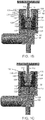
- FIG. 1A illustrates an elevator car parking brake according to an embodiment.
- the elevator car parking brake comprises a housing 108.
- the housing 108 comprises an opening configured to receive a guide rail 110.
- the guide rail 110 moves in the opening without touching any parts of the housing 108.
- the housing 108 may comprise a top plate and a base plate between which an operating fork or an operating member 102 is arranged.
- the operating fork 102 may have a cross-sectional shape of a stable or a saddle.
- the operating fork 102 is configured to move within the housing 108 in a direction perpendicular to an end surface 116 of the guide rail 110.
- a width of the operating fork 102 may be configured to be slightly smaller than an inner width of the housing 108 to enable the operating fork 102 to move within the housing 108 in a direction perpendicular to the end surface 116 of the guide rail 110.
- the elevator car parking brake comprises also an actuator 100.
- the operating fork 102 is configured to be moved within the housing 108 in a direction perpendicular to the end surface of the guide rail 110 in response to operation of the actuator 100.
- the actuator 100 may comprise a bar 120 or other element that moves to push the operating fork 102 when the parking brake is engaged and pull the operating fork 102 when the parking brake is disengaged.
- the elevator car parking brake further comprises braking wedges 106 arranged within the housing 108 at opposite sides of the opening 114 to face side surfaces 118 of the guide rail 110.
- an inner surface of the braking wedge 106 may be arranged in parallel with respect to the side surface 118 of the guide rail 110.
- An outer surface 126 of the braking wedge 106 may be slanted with respect to the inner surface 122 of the braking wedge 106.
- the braking wedges 106 may be arranged within the housing 108 so that slanted surfaces of the braking wedges 106 face slanted surfaces 128 of the operating fork 102.
- the elevator car parking brake also comprises detaching means 104 attached to each braking wedge 106.
- the detaching means 104 may comprise springs or any other means that are able to pull the braking wedges 106 away from the side surfaces 118 of the guide rail 110 upon disengaging of the parking brake.
- FIG. 1B illustrates a cross-sectional top view of the elevator car parking brake illustrated in FIG. 1A . More specifically, FIG. 1B illustrates a situation where the actuator 100 (or the bar 120) has started to push the operating fork 102 towards the guide rail 110 to engage the parking brake.
- the actuator 100 is operated to move the operating fork 102 within the housing 108 towards the guide rail 110 to achieve a braking state
- the operating fork 102 is configured to push the braking wedges 106 towards the side surfaces 118 of the guide rail 110 to contact the side surfaces 118.
- FIG. 1B illustrates a cross-sectional top view of the elevator car parking brake illustrated in FIG. 1A . More specifically, FIG. 1B illustrates a situation where the actuator 100 (or the bar 120) has started to push the operating fork 102 towards the guide rail 110 to engage the parking brake.
- the actuator 100 is operated to move the operating fork 102 within the housing 108 towards the guide rail 110 to achieve a braking state
- the operating fork 102
- a first space 132 between a lower end portion 134 of the operating fork 102 and an inner surface of the housing 108 grows and a second space 130 between an upper end portion 136 of the operating fork 102 and an inner surface of the housing 108 decreases.
- the slanted surface 128 of the operating fork 108 pushes against the slanted surface 126 of the braking wedge 106, thus causing the braking wedge 106 to move towards the side surface 118 of the guide rail 110.
- the housing 108 may be configured to limit movement of the braking wedges 106 only in a direction substantially perpendicular to the side surfaces 118 of the guide rail 110.
- the movement limitation may be achieved, for example, with a guide 124, supported between the top and base plates of the housing 108, and end surfaces 112 of the housing 108.
- the top and base plates of the housing 108 may be machined to accommodate braking wedges 106 that are slightly higher than the operating fork 102 such that only a braking wedge 106 movement perpendicular to operating fork 102 movement is enabled.
- FIG. 1C illustrates another cross-sectional top view of the elevator car parking brake illustrated in FIG. 1A . More specifically, FIG. 1C illustrates a situation where the elevator car parking brake has reached a braking state. In the braking state, the braking wedges 106 press against the side surfaces 118 of the guide rail 110 and the detaching means 104 are in an extended state. As can be seen by comparing FIGS. 1B and 1C , the first space 132 between the lower end portion 134 of the operating fork 102 and the inner surface of the housing 108 has grown significantly and the second space 130 between the upper end portion 136 of the operating fork 102 and the inner surface of the housing 108 has decreased significantly.
- the detaching means 104 are configured to pull the braking wedges 106 away from the side surfaces 118 of the guide rail 110.
- one end of the detaching means 104 may be attached or fixed to the housing 108. In another, alternative embodiment, one end of the detaching means 104 may be attached or fixed to the operating fork 102.
- the elevator car parking brake works in such a way that when the elevator is ready to move and suspension rope forces are balanced, the operating fork 102 is pulled back to a retracted position within the housing 108 and the detaching means 104 pull the braking wedges 106 off from the guide rail 110 and elevator is free to move.
- the movement of the braking wedges 106 may be designed so that a gap between the side surfaces 118 of the guide rail 110 and braking wedges 106 is big enough when the elevator moves.
- the housing 108 may prevent the movement of the braking wedges 106 in other directions that towards the guide rail 110 / away from the guide rail 110.
- the housing 108 may be fixed to a sling of an elevator car. As illustrated in FIG. 2 , when the load inside the car changes, the elevator car would move up or down due to the changed tension in the suspension ropes without the parking brake keeping it stationary by transmitting the force resulting from the load change to the guide rails.
- the actuator 100 comprises an electric motor.
- the elevator car parking brake may comprise a controller configured to calculate revolutions of the electric motor, for example by an encoder, when the actuator 100 is operated to move the operating fork 102 within the housing 108 towards the guide rail 110 to achieve the braking state, and determine wearing of the braking wedges 106 based on the calculated revolutions.
- the braking wedges 106 wear out, they need to be moved a longer distance towards the side surfaces 118 of the guide rail 110 in order to achieve a proper braking state.
- the controller may also be configured to issue a wearing alert when the number of revolutions exceeds a predefined threshold value. This may also mean that the braking wedges may need to be replaced with new ones.
- the actuator may comprise an electro-mechanical linear actuator, a hydraulic cylinder or a pneumatic cylinder.
- An elevator of an elevator system may comprise at least one elevator car parking brake discussed above.
- the illustrated solution provides a compact elevator car parking brake. Further, the actuator can be placed between top beams of a sling and under a roller guide bracket.
- the working principle of the solution is simple and it does not need an extensive number of components. This means that the solution is reliable and long-lasting.
- braking wedges when using braking wedges, they amplify the thrust so that the actuator can be relatively small. As an example, when a 10-degree wedge angle is used, a 25kN compression force can be reached approximately with a 5kN thrust force. Further, to achieve a 5mm air gap between the guide rail 110 and braking wedges 106, the movement of the operating fork 102 is approximately 25mm.
Landscapes
- Engineering & Computer Science (AREA)
- Mechanical Engineering (AREA)
- Automation & Control Theory (AREA)
- Structural Engineering (AREA)
- Computer Networks & Wireless Communication (AREA)
- Civil Engineering (AREA)
- Braking Arrangements (AREA)
- Maintenance And Inspection Apparatuses For Elevators (AREA)
Abstract
Description
- An elevator car needs to be kept within a door zone at a landing so that the car door sill and the landing door sill are on the same level for safe boarding and exit of passengers. Due to elasticity of hoisting ropes, a load change in the elevator car and the resulting tension change in hoisting ropes will move the car and create a step between the car and landing posing a tripping hazard. Relevelling of the car by machinery is a known method for preventing such tripping hazard. However, precision positioning of the car is a complex task and the dynamic load change during loading and unloading of the car will most likely make the process iterative.
- A parking brake solves the problem that is due the suspension elasticity during loading and unloading. The parking brake holds the elevator in its place during loading and unloading and releases its grip after the load has been transferred to the suspension ropes and the car and landing doors have been closed, before the elevator starts to run again.
- As the parking brakes are engaged at every landing stop of the elevator car, they need to be reliable and endure long-term use. Therefore, there is a need for a parking brake solution that would provide a simple but efficient parking brake.
- According to a first aspect, there is provided an elevator car parking brake comprising a housing having an opening configured to receive at least part of a guide rail; an actuator; an operating fork configured to move within the housing in a direction perpendicular to an end surface of the guide rail in response to operating the actuator; braking wedges arranged within the housing at opposite sides of the opening to face side surfaces of the guide rail; and detaching means attached to each braking wedge. When the actuator is operated to move the operating fork within the housing towards the guide rail to achieve a braking state, the operating fork is configured to push the braking wedges towards the side surfaces of the guide rail to contact the side surfaces. Further, when the actuator is operated to move the operating fork within the housing away from the guide rail to achieve a brake release state, the detaching means are configured to pull the braking wedges away from the side surfaces of the guide rail.
- In an embodiment, the braking wedges are arranged within the housing so that slanted surfaces of the braking wedges face slanted surfaces of the operating fork.
- In an embodiment, alternatively or in addition, the housing is configured to limit movement of the braking wedges only in a direction substantially perpendicular to the side surfaces of the guide rail.
- In an embodiment, alternatively or in addition, the detaching means comprise a spring.
- In an embodiment, alternatively or in addition, one end of the detaching means is attached to the housing or the operating fork.
- In an embodiment, the actuator comprises an electric motor.
- In an embodiment, the elevator car parking brake further comprises a controller configured to calculate revolutions of the electric motor when the actuator is operated to move the operating fork within the housing towards the guide rail to achieve the braking state; and determine wearing of the braking wedges based on the calculated revolutions.
- In an embodiment, alternatively or in addition, the controller is configured to issue a wearing alert when the number of revolutions exceeds a predefined threshold value.
- According to a second aspect, there is provided an elevator comprising an elevator car parking brake of the first aspect.
- The accompanying drawings, which are included to provide a further understanding of the invention and constitute a part of this specification, illustrate embodiments of the invention and together with the description help to explain the principles of the invention. In the drawings:
-
FIG. 1A illustrates an elevator car parking brake according to an embodiment. -
FIG. 1B illustrates a top view of the elevator car parking brake illustrated inFIG. 1A . -
FIG. 1C illustrates another top view of the elevator car parking brake illustrated inFIG. 1A . -
FIG. 2 illustrates an embodiment where the housing transmits a change of load to braking wedges. - The following description illustrates a solution for an elevator car parking brake.
-
FIG. 1A illustrates an elevator car parking brake according to an embodiment. The elevator car parking brake comprises ahousing 108. Thehousing 108 comprises an opening configured to receive aguide rail 110. When the parking brake is not used and the elevator moves, theguide rail 110 moves in the opening without touching any parts of thehousing 108. - The
housing 108 may comprise a top plate and a base plate between which an operating fork or anoperating member 102 is arranged. Theoperating fork 102 may have a cross-sectional shape of a stable or a saddle. Theoperating fork 102 is configured to move within thehousing 108 in a direction perpendicular to anend surface 116 of theguide rail 110. As can be seen fromFIG. 1A (and more clearly fromFIGS. 1B and 1C ), a width of theoperating fork 102 may be configured to be slightly smaller than an inner width of thehousing 108 to enable theoperating fork 102 to move within thehousing 108 in a direction perpendicular to theend surface 116 of theguide rail 110. - The elevator car parking brake comprises also an
actuator 100. Theoperating fork 102 is configured to be moved within thehousing 108 in a direction perpendicular to the end surface of theguide rail 110 in response to operation of theactuator 100. Theactuator 100 may comprise abar 120 or other element that moves to push theoperating fork 102 when the parking brake is engaged and pull theoperating fork 102 when the parking brake is disengaged. - The elevator car parking brake further comprises braking
wedges 106 arranged within thehousing 108 at opposite sides of the opening 114 toface side surfaces 118 of theguide rail 110. As can be seen fromFIG. 1A , an inner surface of thebraking wedge 106 may be arranged in parallel with respect to theside surface 118 of theguide rail 110. Anouter surface 126 of thebraking wedge 106 may be slanted with respect to theinner surface 122 of thebraking wedge 106. In one embodiment, as illustrated inFIG. 1A , thebraking wedges 106 may be arranged within thehousing 108 so that slanted surfaces of thebraking wedges 106 faceslanted surfaces 128 of theoperating fork 102. - The elevator car parking brake also comprises detaching means 104 attached to each
braking wedge 106. The detaching means 104 may comprise springs or any other means that are able to pull thebraking wedges 106 away from theside surfaces 118 of theguide rail 110 upon disengaging of the parking brake. -
FIG. 1B illustrates a cross-sectional top view of the elevator car parking brake illustrated inFIG. 1A . More specifically,FIG. 1B illustrates a situation where the actuator 100 (or the bar 120) has started to push theoperating fork 102 towards theguide rail 110 to engage the parking brake. When theactuator 100 is operated to move theoperating fork 102 within thehousing 108 towards theguide rail 110 to achieve a braking state, theoperating fork 102 is configured to push thebraking wedges 106 towards theside surfaces 118 of theguide rail 110 to contact theside surfaces 118. As can be seen fromFIG. 1B , afirst space 132 between alower end portion 134 of theoperating fork 102 and an inner surface of thehousing 108 grows and asecond space 130 between anupper end portion 136 of theoperating fork 102 and an inner surface of thehousing 108 decreases. - At the same time, the
slanted surface 128 of theoperating fork 108 pushes against the slantedsurface 126 of thebraking wedge 106, thus causing thebraking wedge 106 to move towards theside surface 118 of theguide rail 110. - As can be seen from
FIG. 1B , thehousing 108 may be configured to limit movement of the brakingwedges 106 only in a direction substantially perpendicular to the side surfaces 118 of theguide rail 110. The movement limitation may be achieved, for example, with aguide 124, supported between the top and base plates of thehousing 108, and endsurfaces 112 of thehousing 108. The top and base plates of thehousing 108 may be machined to accommodatebraking wedges 106 that are slightly higher than theoperating fork 102 such that only abraking wedge 106 movement perpendicular to operatingfork 102 movement is enabled. -
FIG. 1C illustrates another cross-sectional top view of the elevator car parking brake illustrated inFIG. 1A . More specifically,FIG. 1C illustrates a situation where the elevator car parking brake has reached a braking state. In the braking state, the brakingwedges 106 press against the side surfaces 118 of theguide rail 110 and the detaching means 104 are in an extended state. As can be seen by comparingFIGS. 1B and 1C , thefirst space 132 between thelower end portion 134 of theoperating fork 102 and the inner surface of thehousing 108 has grown significantly and thesecond space 130 between theupper end portion 136 of theoperating fork 102 and the inner surface of thehousing 108 has decreased significantly. - When the
actuator 100 is operated again to move theoperating fork 102 within thehousing 108 away from theguide rail 110 to achieve a brake release state, the detaching means 104 are configured to pull thebraking wedges 106 away from the side surfaces 118 of theguide rail 110. In an embodiment, one end of the detaching means 104 may be attached or fixed to thehousing 108. In another, alternative embodiment, one end of the detaching means 104 may be attached or fixed to theoperating fork 102. - As a summary of
FIGS. 1A-1C , the elevator car parking brake works in such a way that when the elevator is ready to move and suspension rope forces are balanced, theoperating fork 102 is pulled back to a retracted position within thehousing 108 and the detaching means 104 pull thebraking wedges 106 off from theguide rail 110 and elevator is free to move. The movement of the brakingwedges 106 may be designed so that a gap between the side surfaces 118 of theguide rail 110 and brakingwedges 106 is big enough when the elevator moves. When the elevator stops for loading and unloading, the parking brake is engaged by pushing theoperating fork 102 forward by theactuator 100. Theoperating fork 102 then pushes the brakingwedges 106 against the side surfaces 118 of theguide rail 110. - Although not shown in
FIGS. 1A-1C , thehousing 108 may prevent the movement of the brakingwedges 106 in other directions that towards theguide rail 110 / away from theguide rail 110. - In one embodiment, the
housing 108 may be fixed to a sling of an elevator car. As illustrated inFIG. 2 , when the load inside the car changes, the elevator car would move up or down due to the changed tension in the suspension ropes without the parking brake keeping it stationary by transmitting the force resulting from the load change to the guide rails. - In one embodiment, the
actuator 100 comprises an electric motor. Further, the elevator car parking brake may comprise a controller configured to calculate revolutions of the electric motor, for example by an encoder, when theactuator 100 is operated to move theoperating fork 102 within thehousing 108 towards theguide rail 110 to achieve the braking state, and determine wearing of the brakingwedges 106 based on the calculated revolutions. In other words, when the brakingwedges 106 wear out, they need to be moved a longer distance towards the side surfaces 118 of theguide rail 110 in order to achieve a proper braking state. This means that the electric motor has to be operated longer (i.e. the number of revolutions performed by the electric motor increases) in order to achieve a proper braking state. The controller may also be configured to issue a wearing alert when the number of revolutions exceeds a predefined threshold value. This may also mean that the braking wedges may need to be replaced with new ones. - In other embodiments, the actuator may comprise an electro-mechanical linear actuator, a hydraulic cylinder or a pneumatic cylinder.
- An elevator of an elevator system may comprise at least one elevator car parking brake discussed above.
- The illustrated solution provides a compact elevator car parking brake. Further, the actuator can be placed between top beams of a sling and under a roller guide bracket. The working principle of the solution is simple and it does not need an extensive number of components. This means that the solution is reliable and long-lasting.
- Further, when using braking wedges, they amplify the thrust so that the actuator can be relatively small. As an example, when a 10-degree wedge angle is used, a 25kN compression force can be reached approximately with a 5kN thrust force. Further, to achieve a 5mm air gap between the
guide rail 110 and brakingwedges 106, the movement of theoperating fork 102 is approximately 25mm. - While there have been shown and described and pointed out fundamental novel features as applied to preferred embodiments thereof, it will be understood that various omissions and substitutions and changes in the form and details of the devices and methods described may be made by those skilled in the art without departing from the spirit of the disclosure. Moreover, it should be recognized that structures and/or elements and/or method steps shown and/or described in connection with any disclosed form or embodiments may be incorporated in any other disclosed or described or suggested form or embodiment as a general matter of design choice. Furthermore, in the claims means-plus-function clauses are intended to cover the structures described herein as performing the recited function and not only structural equivalents, but also equivalent structures.
- The applicant hereby discloses in isolation each individual feature described herein and any combination of two or more such features, to the extent that such features or combinations are capable of being carried out based on the present specification as a whole, in the light of the common general knowledge of a person skilled in the art, irrespective of whether such features or combinations of features solve any problems disclosed herein, and without limitation to the scope of the claims. The applicant indicates that the disclosed aspects/embodiments may consist of any such individual feature or combination of features. In view of the foregoing description it will be evident to a person skilled in the art that various modifications may be made within the scope of the disclosure.
Claims (9)
- An elevator car parking brake comprising:a housing (108) having an opening (114) configured to receive at least part of a guide rail (110) ;an actuator (100);an operating fork (102) configured to move within the housing (108) in a direction perpendicular to an end surface of the guide rail (110) in response to operating the actuator (100);braking wedges (106) arranged within the housing (108) at opposite sides of the opening (114) to face side surfaces (118) of the guide rail (110);detaching means (104) attached to each braking wedge (106);when the actuator (100) is operated to move the operating fork (102) within the housing (108) towards the guide rail (110) to achieve a braking state, the operating fork (102) is configured to push the braking wedges (106) towards the side surfaces (118) of the guide rail (110) to contact the side surfaces (118); andwhen the actuator (100) is operated to move the operating fork (102) within the housing (108) away from the guide rail (110) to achieve a brake release state, the detaching means (104) are configured to pull the braking wedges (106) away from the side surfaces (118) of the guide rail (110).
- The elevator car parking brake of claim 1, wherein the braking wedges (106) are arranged within the housing (108) so that slanted surfaces of the braking wedges (106) face slanted surfaces of the operating fork (102) .
- The elevator car parking brake of claim 1 or 2, wherein the housing (108) is configured to limit movement of the braking wedges (106) only in a direction substantially perpendicular to the side surfaces (118) of the guide rail (110).
- The elevator car parking brake of any of claims 1 - 3, wherein the detaching means (104) comprise a spring.
- The elevator car parking brake of any of claims 1 - 4, wherein one end of the detaching means (104) is attached to the housing (108) or the operating fork (102).
- The elevator car parking brake of any of claims 1 - 5, wherein the actuator (100) comprises an electric motor.
- The elevator car parking brake of claim 6, further comprising a controller configured to:calculate revolutions of the electric motor when the actuator (100) is operated to move the operating fork (102) within the housing (108) towards the guide rail (110) to achieve the braking state; anddetermine wearing of the braking wedges (106) based on the calculated revolutions.
- The elevator car parking brake of claim 7, wherein the controller is configured to issue a wearing alert when the number of revolutions exceeds a predefined threshold value.
- An elevator comprising an elevator car parking brake of any of claims 1 - 8.
Priority Applications (3)
| Application Number | Priority Date | Filing Date | Title |
|---|---|---|---|
| EP18215986.3A EP3674248B1 (en) | 2018-12-31 | 2018-12-31 | An elevator car parking brake |
| US16/720,701 US11498803B2 (en) | 2018-12-31 | 2019-12-19 | Elevator car parking brake |
| CN201911395077.2A CN111377339B (en) | 2018-12-31 | 2019-12-30 | Elevator car parking brake and elevator |
Applications Claiming Priority (1)
| Application Number | Priority Date | Filing Date | Title |
|---|---|---|---|
| EP18215986.3A EP3674248B1 (en) | 2018-12-31 | 2018-12-31 | An elevator car parking brake |
Publications (2)
| Publication Number | Publication Date |
|---|---|
| EP3674248A1 true EP3674248A1 (en) | 2020-07-01 |
| EP3674248B1 EP3674248B1 (en) | 2022-09-07 |
Family
ID=64949105
Family Applications (1)
| Application Number | Title | Priority Date | Filing Date |
|---|---|---|---|
| EP18215986.3A Active EP3674248B1 (en) | 2018-12-31 | 2018-12-31 | An elevator car parking brake |
Country Status (3)
| Country | Link |
|---|---|
| US (1) | US11498803B2 (en) |
| EP (1) | EP3674248B1 (en) |
| CN (1) | CN111377339B (en) |
Families Citing this family (4)
| Publication number | Priority date | Publication date | Assignee | Title |
|---|---|---|---|---|
| EP3674248B1 (en) * | 2018-12-31 | 2022-09-07 | KONE Corporation | An elevator car parking brake |
| AU2020405929B2 (en) * | 2019-12-17 | 2024-07-18 | Inventio Ag | Safety brake for an elevator |
| US11834300B2 (en) * | 2021-08-10 | 2023-12-05 | Tk Elevator Innovation And Operations Gmbh | Stabilizing assemblies and methods of use thereof |
| EP4393861A4 (en) * | 2021-08-26 | 2025-09-10 | Hitachi Ltd | ELEVATOR DEVICE |
Citations (4)
| Publication number | Priority date | Publication date | Assignee | Title |
|---|---|---|---|---|
| GB246387A (en) * | 1925-07-24 | 1926-01-28 | Jakob Lichtenberg | Improved safety-device for mine cages |
| US20070051563A1 (en) * | 2003-10-07 | 2007-03-08 | Jae-Hyuk Oh | Remotely resettable ropeless emergency stopping device for an elevator |
| WO2012128758A1 (en) * | 2011-03-22 | 2012-09-27 | Otis Elevator Company | Elevator braking system |
| EP2607287A1 (en) * | 2011-12-19 | 2013-06-26 | Inventio AG | Device for a lift and method of operating a lift |
Family Cites Families (21)
| Publication number | Priority date | Publication date | Assignee | Title |
|---|---|---|---|---|
| FI85129C (en) * | 1989-12-14 | 1992-03-10 | Kone Oy | catching device |
| US5518087A (en) * | 1993-09-11 | 1996-05-21 | Lg Industrial Systems Co., Ltd. | Rail brake apparatus for a linear motor elevator |
| US6371261B1 (en) * | 1997-11-06 | 2002-04-16 | Otis Elevator Company | Molybdenum alloy elevator safety brakes |
| US5819879A (en) * | 1997-11-06 | 1998-10-13 | Otis Elevator Company | Safety brake |
| ES2225530T3 (en) * | 2000-05-25 | 2005-03-16 | Inventio Ag | BRAKING DEVICE FOR AN ELEVATOR. |
| JP4927294B2 (en) * | 2000-06-22 | 2012-05-09 | インベンテイオ・アクテイエンゲゼルシヤフト | Brake restraint device with adaptable braking force for elevators |
| JP2002087727A (en) * | 2000-09-18 | 2002-03-27 | Toshiba Elevator Co Ltd | Elevator safety gear |
| DE112005000607B4 (en) * | 2004-03-15 | 2009-01-22 | Mitsubishi Denki K.K. | Braking device for a lift |
| BRPI0601926B1 (en) * | 2005-06-17 | 2018-06-12 | Inventio Aktiengesellschaft | BRAKE PARACHUTE DEVICE |
| DE602006021240D1 (en) * | 2006-11-08 | 2011-05-19 | Otis Elevator Co | ELEVATOR BRAKE DEVICE |
| DE102011053178B3 (en) * | 2011-08-31 | 2012-11-29 | Klaus-Peter Kapp | Friction brake with an acting perpendicular to the clamping actuator actuator |
| BR112013018423B1 (en) * | 2011-09-30 | 2021-03-16 | Inventio Ag | elevator braking device for braking a travel body of an elevator installation, elevator installation and method of operation of an elevator braking device |
| US9919899B2 (en) * | 2011-12-09 | 2018-03-20 | Inventio Ag | Actuation of a safety brake |
| WO2015126863A2 (en) * | 2014-02-21 | 2015-08-27 | Wurtec Elevator Products & Services | False car device |
| CN106219351B (en) * | 2016-08-30 | 2018-10-02 | 浙江西子富沃德电机有限公司 | a kind of bidirectional safety tongs |
| US11447365B2 (en) * | 2016-12-16 | 2022-09-20 | Inventio Ag | Parking brake |
| US10569993B2 (en) * | 2017-03-29 | 2020-02-25 | Otis Elevator Company | Safety brake actuation mechanism for a hoisted structure |
| DE102017209888A1 (en) * | 2017-06-12 | 2018-12-13 | Thyssenkrupp Ag | Brake for an elevator system |
| EP3674248B1 (en) * | 2018-12-31 | 2022-09-07 | KONE Corporation | An elevator car parking brake |
| DE202019101479U1 (en) * | 2019-03-15 | 2020-06-18 | Inventio Ag | Safety brake device |
| EP3932844A1 (en) * | 2020-07-01 | 2022-01-05 | KONE Corporation | Safety gear arrangement, elevator system, and method for operating a safety gear of an elevator system |
-
2018
- 2018-12-31 EP EP18215986.3A patent/EP3674248B1/en active Active
-
2019
- 2019-12-19 US US16/720,701 patent/US11498803B2/en active Active
- 2019-12-30 CN CN201911395077.2A patent/CN111377339B/en active Active
Patent Citations (4)
| Publication number | Priority date | Publication date | Assignee | Title |
|---|---|---|---|---|
| GB246387A (en) * | 1925-07-24 | 1926-01-28 | Jakob Lichtenberg | Improved safety-device for mine cages |
| US20070051563A1 (en) * | 2003-10-07 | 2007-03-08 | Jae-Hyuk Oh | Remotely resettable ropeless emergency stopping device for an elevator |
| WO2012128758A1 (en) * | 2011-03-22 | 2012-09-27 | Otis Elevator Company | Elevator braking system |
| EP2607287A1 (en) * | 2011-12-19 | 2013-06-26 | Inventio AG | Device for a lift and method of operating a lift |
Also Published As
| Publication number | Publication date |
|---|---|
| US20200207576A1 (en) | 2020-07-02 |
| EP3674248B1 (en) | 2022-09-07 |
| CN111377339B (en) | 2023-04-07 |
| CN111377339A (en) | 2020-07-07 |
| US11498803B2 (en) | 2022-11-15 |
Similar Documents
| Publication | Publication Date | Title |
|---|---|---|
| US11498803B2 (en) | Elevator car parking brake | |
| EP2688825B1 (en) | Elevator braking system | |
| KR102605526B1 (en) | Braking system for a hoisted structure and method of controlling braking a hoisted structure | |
| US20200207575A1 (en) | Elevator car parking brake | |
| RU2590799C2 (en) | Elevator brake system | |
| US20190047820A1 (en) | Traction sheave safety device and elevator car emergency stop method thereof | |
| WO2005102899A1 (en) | Emergency stop system of elevator | |
| CN102421693B (en) | Direct acting wheel brakes for elevators | |
| CN105819302B (en) | Rope brake | |
| CN106687404A (en) | elevator brake | |
| JP5603755B2 (en) | Elevator equipment | |
| JP5501995B2 (en) | Elevator equipment | |
| KR20090122934A (en) | lift | |
| JP2004523441A (en) | Emergency braking and shock absorbers for lift or suspended luggage | |
| EP3674244A1 (en) | An elevator car parking brake | |
| JP5548524B2 (en) | Lifting device with safety device | |
| CN106185528A (en) | The emergency braking device of elevator | |
| JP4594803B2 (en) | Elevator emergency stop device | |
| KR101698546B1 (en) | Safety device for an elevator | |
| CN204342217U (en) | One prevents the uncontrolled Displacement system of lift car | |
| CN1993289B (en) | Traction device for elevator | |
| KR102009999B1 (en) | Unidirectional emergency braking apparatus for elevators | |
| KR20210059380A (en) | Elevator auxiliary binding device | |
| KR20130088291A (en) | Emergency stop apparatus of elevator | |
| JP7665102B2 (en) | Elevator safety devices |
Legal Events
| Date | Code | Title | Description |
|---|---|---|---|
| PUAI | Public reference made under article 153(3) epc to a published international application that has entered the european phase |
Free format text: ORIGINAL CODE: 0009012 |
|
| STAA | Information on the status of an ep patent application or granted ep patent |
Free format text: STATUS: THE APPLICATION HAS BEEN PUBLISHED |
|
| AK | Designated contracting states |
Kind code of ref document: A1 Designated state(s): AL AT BE BG CH CY CZ DE DK EE ES FI FR GB GR HR HU IE IS IT LI LT LU LV MC MK MT NL NO PL PT RO RS SE SI SK SM TR |
|
| AX | Request for extension of the european patent |
Extension state: BA ME |
|
| STAA | Information on the status of an ep patent application or granted ep patent |
Free format text: STATUS: REQUEST FOR EXAMINATION WAS MADE |
|
| 17P | Request for examination filed |
Effective date: 20201231 |
|
| RBV | Designated contracting states (corrected) |
Designated state(s): AL AT BE BG CH CY CZ DE DK EE ES FI FR GB GR HR HU IE IS IT LI LT LU LV MC MK MT NL NO PL PT RO RS SE SI SK SM TR |
|
| GRAP | Despatch of communication of intention to grant a patent |
Free format text: ORIGINAL CODE: EPIDOSNIGR1 |
|
| STAA | Information on the status of an ep patent application or granted ep patent |
Free format text: STATUS: GRANT OF PATENT IS INTENDED |
|
| INTG | Intention to grant announced |
Effective date: 20220406 |
|
| GRAS | Grant fee paid |
Free format text: ORIGINAL CODE: EPIDOSNIGR3 |
|
| GRAA | (expected) grant |
Free format text: ORIGINAL CODE: 0009210 |
|
| STAA | Information on the status of an ep patent application or granted ep patent |
Free format text: STATUS: THE PATENT HAS BEEN GRANTED |
|
| AK | Designated contracting states |
Kind code of ref document: B1 Designated state(s): AL AT BE BG CH CY CZ DE DK EE ES FI FR GB GR HR HU IE IS IT LI LT LU LV MC MK MT NL NO PL PT RO RS SE SI SK SM TR |
|
| REG | Reference to a national code |
Ref country code: GB Ref legal event code: FG4D |
|
| REG | Reference to a national code |
Ref country code: CH Ref legal event code: EP Ref country code: AT Ref legal event code: REF Ref document number: 1516910 Country of ref document: AT Kind code of ref document: T Effective date: 20220915 |
|
| REG | Reference to a national code |
Ref country code: DE Ref legal event code: R096 Ref document number: 602018040284 Country of ref document: DE |
|
| REG | Reference to a national code |
Ref country code: IE Ref legal event code: FG4D |
|
| REG | Reference to a national code |
Ref country code: LT Ref legal event code: MG9D |
|
| REG | Reference to a national code |
Ref country code: NL Ref legal event code: MP Effective date: 20220907 |
|
| PG25 | Lapsed in a contracting state [announced via postgrant information from national office to epo] |
Ref country code: SE Free format text: LAPSE BECAUSE OF FAILURE TO SUBMIT A TRANSLATION OF THE DESCRIPTION OR TO PAY THE FEE WITHIN THE PRESCRIBED TIME-LIMIT Effective date: 20220907 Ref country code: RS Free format text: LAPSE BECAUSE OF FAILURE TO SUBMIT A TRANSLATION OF THE DESCRIPTION OR TO PAY THE FEE WITHIN THE PRESCRIBED TIME-LIMIT Effective date: 20220907 Ref country code: NO Free format text: LAPSE BECAUSE OF FAILURE TO SUBMIT A TRANSLATION OF THE DESCRIPTION OR TO PAY THE FEE WITHIN THE PRESCRIBED TIME-LIMIT Effective date: 20221207 Ref country code: LV Free format text: LAPSE BECAUSE OF FAILURE TO SUBMIT A TRANSLATION OF THE DESCRIPTION OR TO PAY THE FEE WITHIN THE PRESCRIBED TIME-LIMIT Effective date: 20220907 Ref country code: LT Free format text: LAPSE BECAUSE OF FAILURE TO SUBMIT A TRANSLATION OF THE DESCRIPTION OR TO PAY THE FEE WITHIN THE PRESCRIBED TIME-LIMIT Effective date: 20220907 Ref country code: FI Free format text: LAPSE BECAUSE OF FAILURE TO SUBMIT A TRANSLATION OF THE DESCRIPTION OR TO PAY THE FEE WITHIN THE PRESCRIBED TIME-LIMIT Effective date: 20220907 |
|
| REG | Reference to a national code |
Ref country code: AT Ref legal event code: MK05 Ref document number: 1516910 Country of ref document: AT Kind code of ref document: T Effective date: 20220907 |
|
| PG25 | Lapsed in a contracting state [announced via postgrant information from national office to epo] |
Ref country code: HR Free format text: LAPSE BECAUSE OF FAILURE TO SUBMIT A TRANSLATION OF THE DESCRIPTION OR TO PAY THE FEE WITHIN THE PRESCRIBED TIME-LIMIT Effective date: 20220907 Ref country code: GR Free format text: LAPSE BECAUSE OF FAILURE TO SUBMIT A TRANSLATION OF THE DESCRIPTION OR TO PAY THE FEE WITHIN THE PRESCRIBED TIME-LIMIT Effective date: 20221208 |
|
| PG25 | Lapsed in a contracting state [announced via postgrant information from national office to epo] |
Ref country code: SM Free format text: LAPSE BECAUSE OF FAILURE TO SUBMIT A TRANSLATION OF THE DESCRIPTION OR TO PAY THE FEE WITHIN THE PRESCRIBED TIME-LIMIT Effective date: 20220907 Ref country code: RO Free format text: LAPSE BECAUSE OF FAILURE TO SUBMIT A TRANSLATION OF THE DESCRIPTION OR TO PAY THE FEE WITHIN THE PRESCRIBED TIME-LIMIT Effective date: 20220907 Ref country code: PT Free format text: LAPSE BECAUSE OF FAILURE TO SUBMIT A TRANSLATION OF THE DESCRIPTION OR TO PAY THE FEE WITHIN THE PRESCRIBED TIME-LIMIT Effective date: 20230109 Ref country code: ES Free format text: LAPSE BECAUSE OF FAILURE TO SUBMIT A TRANSLATION OF THE DESCRIPTION OR TO PAY THE FEE WITHIN THE PRESCRIBED TIME-LIMIT Effective date: 20220907 Ref country code: CZ Free format text: LAPSE BECAUSE OF FAILURE TO SUBMIT A TRANSLATION OF THE DESCRIPTION OR TO PAY THE FEE WITHIN THE PRESCRIBED TIME-LIMIT Effective date: 20220907 Ref country code: AT Free format text: LAPSE BECAUSE OF FAILURE TO SUBMIT A TRANSLATION OF THE DESCRIPTION OR TO PAY THE FEE WITHIN THE PRESCRIBED TIME-LIMIT Effective date: 20220907 |
|
| PG25 | Lapsed in a contracting state [announced via postgrant information from national office to epo] |
Ref country code: SK Free format text: LAPSE BECAUSE OF FAILURE TO SUBMIT A TRANSLATION OF THE DESCRIPTION OR TO PAY THE FEE WITHIN THE PRESCRIBED TIME-LIMIT Effective date: 20220907 Ref country code: PL Free format text: LAPSE BECAUSE OF FAILURE TO SUBMIT A TRANSLATION OF THE DESCRIPTION OR TO PAY THE FEE WITHIN THE PRESCRIBED TIME-LIMIT Effective date: 20220907 Ref country code: IS Free format text: LAPSE BECAUSE OF FAILURE TO SUBMIT A TRANSLATION OF THE DESCRIPTION OR TO PAY THE FEE WITHIN THE PRESCRIBED TIME-LIMIT Effective date: 20230107 Ref country code: EE Free format text: LAPSE BECAUSE OF FAILURE TO SUBMIT A TRANSLATION OF THE DESCRIPTION OR TO PAY THE FEE WITHIN THE PRESCRIBED TIME-LIMIT Effective date: 20220907 |
|
| REG | Reference to a national code |
Ref country code: DE Ref legal event code: R097 Ref document number: 602018040284 Country of ref document: DE |
|
| PG25 | Lapsed in a contracting state [announced via postgrant information from national office to epo] |
Ref country code: NL Free format text: LAPSE BECAUSE OF FAILURE TO SUBMIT A TRANSLATION OF THE DESCRIPTION OR TO PAY THE FEE WITHIN THE PRESCRIBED TIME-LIMIT Effective date: 20220907 Ref country code: AL Free format text: LAPSE BECAUSE OF FAILURE TO SUBMIT A TRANSLATION OF THE DESCRIPTION OR TO PAY THE FEE WITHIN THE PRESCRIBED TIME-LIMIT Effective date: 20220907 |
|
| P01 | Opt-out of the competence of the unified patent court (upc) registered |
Effective date: 20230525 |
|
| PLBE | No opposition filed within time limit |
Free format text: ORIGINAL CODE: 0009261 |
|
| STAA | Information on the status of an ep patent application or granted ep patent |
Free format text: STATUS: NO OPPOSITION FILED WITHIN TIME LIMIT |
|
| PG25 | Lapsed in a contracting state [announced via postgrant information from national office to epo] |
Ref country code: DK Free format text: LAPSE BECAUSE OF FAILURE TO SUBMIT A TRANSLATION OF THE DESCRIPTION OR TO PAY THE FEE WITHIN THE PRESCRIBED TIME-LIMIT Effective date: 20220907 |
|
| REG | Reference to a national code |
Ref country code: CH Ref legal event code: PL |
|
| 26N | No opposition filed |
Effective date: 20230608 |
|
| REG | Reference to a national code |
Ref country code: BE Ref legal event code: MM Effective date: 20221231 |
|
| PG25 | Lapsed in a contracting state [announced via postgrant information from national office to epo] |
Ref country code: SI Free format text: LAPSE BECAUSE OF FAILURE TO SUBMIT A TRANSLATION OF THE DESCRIPTION OR TO PAY THE FEE WITHIN THE PRESCRIBED TIME-LIMIT Effective date: 20220907 Ref country code: LU Free format text: LAPSE BECAUSE OF NON-PAYMENT OF DUE FEES Effective date: 20221231 |
|
| PG25 | Lapsed in a contracting state [announced via postgrant information from national office to epo] |
Ref country code: LI Free format text: LAPSE BECAUSE OF NON-PAYMENT OF DUE FEES Effective date: 20221231 Ref country code: IE Free format text: LAPSE BECAUSE OF NON-PAYMENT OF DUE FEES Effective date: 20221231 Ref country code: CH Free format text: LAPSE BECAUSE OF NON-PAYMENT OF DUE FEES Effective date: 20221231 |
|
| PG25 | Lapsed in a contracting state [announced via postgrant information from national office to epo] |
Ref country code: BE Free format text: LAPSE BECAUSE OF NON-PAYMENT OF DUE FEES Effective date: 20221231 |
|
| PG25 | Lapsed in a contracting state [announced via postgrant information from national office to epo] |
Ref country code: HU Free format text: LAPSE BECAUSE OF FAILURE TO SUBMIT A TRANSLATION OF THE DESCRIPTION OR TO PAY THE FEE WITHIN THE PRESCRIBED TIME-LIMIT; INVALID AB INITIO Effective date: 20181231 |
|
| PG25 | Lapsed in a contracting state [announced via postgrant information from national office to epo] |
Ref country code: CY Free format text: LAPSE BECAUSE OF FAILURE TO SUBMIT A TRANSLATION OF THE DESCRIPTION OR TO PAY THE FEE WITHIN THE PRESCRIBED TIME-LIMIT Effective date: 20220907 |
|
| PG25 | Lapsed in a contracting state [announced via postgrant information from national office to epo] |
Ref country code: MK Free format text: LAPSE BECAUSE OF FAILURE TO SUBMIT A TRANSLATION OF THE DESCRIPTION OR TO PAY THE FEE WITHIN THE PRESCRIBED TIME-LIMIT Effective date: 20220907 Ref country code: IT Free format text: LAPSE BECAUSE OF FAILURE TO SUBMIT A TRANSLATION OF THE DESCRIPTION OR TO PAY THE FEE WITHIN THE PRESCRIBED TIME-LIMIT Effective date: 20220907 |
|
| PG25 | Lapsed in a contracting state [announced via postgrant information from national office to epo] |
Ref country code: MC Free format text: LAPSE BECAUSE OF FAILURE TO SUBMIT A TRANSLATION OF THE DESCRIPTION OR TO PAY THE FEE WITHIN THE PRESCRIBED TIME-LIMIT Effective date: 20220907 |
|
| PG25 | Lapsed in a contracting state [announced via postgrant information from national office to epo] |
Ref country code: TR Free format text: LAPSE BECAUSE OF FAILURE TO SUBMIT A TRANSLATION OF THE DESCRIPTION OR TO PAY THE FEE WITHIN THE PRESCRIBED TIME-LIMIT Effective date: 20220907 Ref country code: MC Free format text: LAPSE BECAUSE OF FAILURE TO SUBMIT A TRANSLATION OF THE DESCRIPTION OR TO PAY THE FEE WITHIN THE PRESCRIBED TIME-LIMIT Effective date: 20220907 |
|
| PG25 | Lapsed in a contracting state [announced via postgrant information from national office to epo] |
Ref country code: BG Free format text: LAPSE BECAUSE OF FAILURE TO SUBMIT A TRANSLATION OF THE DESCRIPTION OR TO PAY THE FEE WITHIN THE PRESCRIBED TIME-LIMIT Effective date: 20220907 |
|
| PG25 | Lapsed in a contracting state [announced via postgrant information from national office to epo] |
Ref country code: MT Free format text: LAPSE BECAUSE OF FAILURE TO SUBMIT A TRANSLATION OF THE DESCRIPTION OR TO PAY THE FEE WITHIN THE PRESCRIBED TIME-LIMIT Effective date: 20220907 |
|
| PGFP | Annual fee paid to national office [announced via postgrant information from national office to epo] |
Ref country code: DE Payment date: 20251211 Year of fee payment: 8 |
|
| PGFP | Annual fee paid to national office [announced via postgrant information from national office to epo] |
Ref country code: GB Payment date: 20251219 Year of fee payment: 8 |
|
| PGFP | Annual fee paid to national office [announced via postgrant information from national office to epo] |
Ref country code: FR Payment date: 20251229 Year of fee payment: 8 |