EP3674247A1 - Elevator with an electrical linear motor - Google Patents
Elevator with an electrical linear motor Download PDFInfo
- Publication number
- EP3674247A1 EP3674247A1 EP20157298.9A EP20157298A EP3674247A1 EP 3674247 A1 EP3674247 A1 EP 3674247A1 EP 20157298 A EP20157298 A EP 20157298A EP 3674247 A1 EP3674247 A1 EP 3674247A1
- Authority
- EP
- European Patent Office
- Prior art keywords
- car
- elevator
- stator
- brake
- elevator car
- Prior art date
- Legal status (The legal status is an assumption and is not a legal conclusion. Google has not performed a legal analysis and makes no representation as to the accuracy of the status listed.)
- Withdrawn
Links
- 238000012360 testing method Methods 0.000 claims description 25
- 238000012544 monitoring process Methods 0.000 claims description 8
- 230000005294 ferromagnetic effect Effects 0.000 claims description 4
- 230000001133 acceleration Effects 0.000 claims description 3
- 230000003247 decreasing effect Effects 0.000 abstract description 9
- 238000000034 method Methods 0.000 abstract description 8
- 238000004804 winding Methods 0.000 description 13
- 230000007246 mechanism Effects 0.000 description 10
- 239000011295 pitch Substances 0.000 description 7
- XEEYBQQBJWHFJM-UHFFFAOYSA-N Iron Chemical compound [Fe] XEEYBQQBJWHFJM-UHFFFAOYSA-N 0.000 description 4
- 238000012423 maintenance Methods 0.000 description 4
- 230000005484 gravity Effects 0.000 description 3
- 230000005540 biological transmission Effects 0.000 description 2
- 230000007423 decrease Effects 0.000 description 2
- 238000010586 diagram Methods 0.000 description 2
- 230000003993 interaction Effects 0.000 description 2
- 229910052742 iron Inorganic materials 0.000 description 2
- 235000000396 iron Nutrition 0.000 description 2
- 230000005291 magnetic effect Effects 0.000 description 2
- 239000002184 metal Substances 0.000 description 2
- 229910052751 metal Inorganic materials 0.000 description 2
- 230000008569 process Effects 0.000 description 2
- 230000002159 abnormal effect Effects 0.000 description 1
- 239000003990 capacitor Substances 0.000 description 1
- 230000008859 change Effects 0.000 description 1
- 238000004891 communication Methods 0.000 description 1
- 238000010276 construction Methods 0.000 description 1
- 230000001419 dependent effect Effects 0.000 description 1
- 238000013461 design Methods 0.000 description 1
- 230000004069 differentiation Effects 0.000 description 1
- 238000005516 engineering process Methods 0.000 description 1
- 230000000977 initiatory effect Effects 0.000 description 1
- 239000000725 suspension Substances 0.000 description 1
Images




Classifications
-
- B—PERFORMING OPERATIONS; TRANSPORTING
- B66—HOISTING; LIFTING; HAULING
- B66B—ELEVATORS; ESCALATORS OR MOVING WALKWAYS
- B66B11/00—Main component parts of lifts in, or associated with, buildings or other structures
- B66B11/04—Driving gear ; Details thereof, e.g. seals
- B66B11/0407—Driving gear ; Details thereof, e.g. seals actuated by an electrical linear motor
-
- B—PERFORMING OPERATIONS; TRANSPORTING
- B66—HOISTING; LIFTING; HAULING
- B66B—ELEVATORS; ESCALATORS OR MOVING WALKWAYS
- B66B7/00—Other common features of elevators
- B66B7/02—Guideways; Guides
- B66B7/04—Riding means, e.g. Shoes, Rollers, between car and guiding means, e.g. rails, ropes
- B66B7/041—Riding means, e.g. Shoes, Rollers, between car and guiding means, e.g. rails, ropes including active attenuation system for shocks, vibrations
- B66B7/044—Riding means, e.g. Shoes, Rollers, between car and guiding means, e.g. rails, ropes including active attenuation system for shocks, vibrations with magnetic or electromagnetic means
-
- B—PERFORMING OPERATIONS; TRANSPORTING
- B66—HOISTING; LIFTING; HAULING
- B66B—ELEVATORS; ESCALATORS OR MOVING WALKWAYS
- B66B1/00—Control systems of elevators in general
- B66B1/24—Control systems with regulation, i.e. with retroactive action, for influencing travelling speed, acceleration, or deceleration
- B66B1/28—Control systems with regulation, i.e. with retroactive action, for influencing travelling speed, acceleration, or deceleration electrical
-
- B—PERFORMING OPERATIONS; TRANSPORTING
- B66—HOISTING; LIFTING; HAULING
- B66B—ELEVATORS; ESCALATORS OR MOVING WALKWAYS
- B66B1/00—Control systems of elevators in general
- B66B1/24—Control systems with regulation, i.e. with retroactive action, for influencing travelling speed, acceleration, or deceleration
- B66B1/28—Control systems with regulation, i.e. with retroactive action, for influencing travelling speed, acceleration, or deceleration electrical
- B66B1/32—Control systems with regulation, i.e. with retroactive action, for influencing travelling speed, acceleration, or deceleration electrical effective on braking devices, e.g. acting on electrically controlled brakes
-
- B—PERFORMING OPERATIONS; TRANSPORTING
- B66—HOISTING; LIFTING; HAULING
- B66B—ELEVATORS; ESCALATORS OR MOVING WALKWAYS
- B66B1/00—Control systems of elevators in general
- B66B1/34—Details, e.g. call counting devices, data transmission from car to control system, devices giving information to the control system
- B66B1/3415—Control system configuration and the data transmission or communication within the control system
- B66B1/3446—Data transmission or communication within the control system
- B66B1/3453—Procedure or protocol for the data transmission or communication
-
- B—PERFORMING OPERATIONS; TRANSPORTING
- B66—HOISTING; LIFTING; HAULING
- B66B—ELEVATORS; ESCALATORS OR MOVING WALKWAYS
- B66B1/00—Control systems of elevators in general
- B66B1/34—Details, e.g. call counting devices, data transmission from car to control system, devices giving information to the control system
- B66B1/3415—Control system configuration and the data transmission or communication within the control system
- B66B1/3446—Data transmission or communication within the control system
- B66B1/3461—Data transmission or communication within the control system between the elevator control system and remote or mobile stations
-
- B—PERFORMING OPERATIONS; TRANSPORTING
- B66—HOISTING; LIFTING; HAULING
- B66B—ELEVATORS; ESCALATORS OR MOVING WALKWAYS
- B66B1/00—Control systems of elevators in general
- B66B1/34—Details, e.g. call counting devices, data transmission from car to control system, devices giving information to the control system
- B66B1/3476—Load weighing or car passenger counting devices
-
- B—PERFORMING OPERATIONS; TRANSPORTING
- B66—HOISTING; LIFTING; HAULING
- B66B—ELEVATORS; ESCALATORS OR MOVING WALKWAYS
- B66B1/00—Control systems of elevators in general
- B66B1/34—Details, e.g. call counting devices, data transmission from car to control system, devices giving information to the control system
- B66B1/3492—Position or motion detectors or driving means for the detector
-
- B—PERFORMING OPERATIONS; TRANSPORTING
- B66—HOISTING; LIFTING; HAULING
- B66B—ELEVATORS; ESCALATORS OR MOVING WALKWAYS
- B66B1/00—Control systems of elevators in general
- B66B1/34—Details, e.g. call counting devices, data transmission from car to control system, devices giving information to the control system
- B66B1/36—Means for stopping the cars, cages, or skips at predetermined levels
-
- B—PERFORMING OPERATIONS; TRANSPORTING
- B66—HOISTING; LIFTING; HAULING
- B66B—ELEVATORS; ESCALATORS OR MOVING WALKWAYS
- B66B5/00—Applications of checking, fault-correcting, or safety devices in elevators
- B66B5/0006—Monitoring devices or performance analysers
- B66B5/0018—Devices monitoring the operating condition of the elevator system
- B66B5/0025—Devices monitoring the operating condition of the elevator system for maintenance or repair
-
- B—PERFORMING OPERATIONS; TRANSPORTING
- B66—HOISTING; LIFTING; HAULING
- B66B—ELEVATORS; ESCALATORS OR MOVING WALKWAYS
- B66B5/00—Applications of checking, fault-correcting, or safety devices in elevators
- B66B5/0006—Monitoring devices or performance analysers
- B66B5/0018—Devices monitoring the operating condition of the elevator system
- B66B5/0031—Devices monitoring the operating condition of the elevator system for safety reasons
-
- B—PERFORMING OPERATIONS; TRANSPORTING
- B66—HOISTING; LIFTING; HAULING
- B66B—ELEVATORS; ESCALATORS OR MOVING WALKWAYS
- B66B5/00—Applications of checking, fault-correcting, or safety devices in elevators
- B66B5/0006—Monitoring devices or performance analysers
- B66B5/0037—Performance analysers
-
- B—PERFORMING OPERATIONS; TRANSPORTING
- B66—HOISTING; LIFTING; HAULING
- B66B—ELEVATORS; ESCALATORS OR MOVING WALKWAYS
- B66B5/00—Applications of checking, fault-correcting, or safety devices in elevators
- B66B5/0087—Devices facilitating maintenance, repair or inspection tasks
- B66B5/0093—Testing of safety devices
-
- B—PERFORMING OPERATIONS; TRANSPORTING
- B66—HOISTING; LIFTING; HAULING
- B66B—ELEVATORS; ESCALATORS OR MOVING WALKWAYS
- B66B5/00—Applications of checking, fault-correcting, or safety devices in elevators
- B66B5/02—Applications of checking, fault-correcting, or safety devices in elevators responsive to abnormal operating conditions
- B66B5/027—Applications of checking, fault-correcting, or safety devices in elevators responsive to abnormal operating conditions to permit passengers to leave an elevator car in case of failure, e.g. moving the car to a reference floor or unlocking the door
-
- B—PERFORMING OPERATIONS; TRANSPORTING
- B66—HOISTING; LIFTING; HAULING
- B66B—ELEVATORS; ESCALATORS OR MOVING WALKWAYS
- B66B5/00—Applications of checking, fault-correcting, or safety devices in elevators
- B66B5/02—Applications of checking, fault-correcting, or safety devices in elevators responsive to abnormal operating conditions
- B66B5/04—Applications of checking, fault-correcting, or safety devices in elevators responsive to abnormal operating conditions for detecting excessive speed
-
- B—PERFORMING OPERATIONS; TRANSPORTING
- B66—HOISTING; LIFTING; HAULING
- B66B—ELEVATORS; ESCALATORS OR MOVING WALKWAYS
- B66B5/00—Applications of checking, fault-correcting, or safety devices in elevators
- B66B5/02—Applications of checking, fault-correcting, or safety devices in elevators responsive to abnormal operating conditions
- B66B5/16—Braking or catch devices operating between cars, cages, or skips and fixed guide elements or surfaces in hoistway or well
-
- B—PERFORMING OPERATIONS; TRANSPORTING
- B66—HOISTING; LIFTING; HAULING
- B66B—ELEVATORS; ESCALATORS OR MOVING WALKWAYS
- B66B5/00—Applications of checking, fault-correcting, or safety devices in elevators
- B66B5/02—Applications of checking, fault-correcting, or safety devices in elevators responsive to abnormal operating conditions
- B66B5/16—Braking or catch devices operating between cars, cages, or skips and fixed guide elements or surfaces in hoistway or well
- B66B5/18—Braking or catch devices operating between cars, cages, or skips and fixed guide elements or surfaces in hoistway or well and applying frictional retarding forces
-
- B—PERFORMING OPERATIONS; TRANSPORTING
- B66—HOISTING; LIFTING; HAULING
- B66B—ELEVATORS; ESCALATORS OR MOVING WALKWAYS
- B66B9/00—Kinds or types of lifts in, or associated with, buildings or other structures
- B66B9/02—Kinds or types of lifts in, or associated with, buildings or other structures actuated mechanically otherwise than by rope or cable
-
- H—ELECTRICITY
- H02—GENERATION; CONVERSION OR DISTRIBUTION OF ELECTRIC POWER
- H02K—DYNAMO-ELECTRIC MACHINES
- H02K41/00—Propulsion systems in which a rigid body is moved along a path due to dynamo-electric interaction between the body and a magnetic field travelling along the path
- H02K41/02—Linear motors; Sectional motors
-
- H—ELECTRICITY
- H02—GENERATION; CONVERSION OR DISTRIBUTION OF ELECTRIC POWER
- H02K—DYNAMO-ELECTRIC MACHINES
- H02K41/00—Propulsion systems in which a rigid body is moved along a path due to dynamo-electric interaction between the body and a magnetic field travelling along the path
- H02K41/02—Linear motors; Sectional motors
- H02K41/03—Synchronous motors; Motors moving step by step; Reluctance motors
- H02K41/031—Synchronous motors; Motors moving step by step; Reluctance motors of the permanent magnet type
- H02K41/033—Synchronous motors; Motors moving step by step; Reluctance motors of the permanent magnet type with armature and magnets on one member, the other member being a flux distributor
-
- H—ELECTRICITY
- H02—GENERATION; CONVERSION OR DISTRIBUTION OF ELECTRIC POWER
- H02K—DYNAMO-ELECTRIC MACHINES
- H02K7/00—Arrangements for handling mechanical energy structurally associated with dynamo-electric machines, e.g. structural association with mechanical driving motors or auxiliary dynamo-electric machines
- H02K7/10—Structural association with clutches, brakes, gears, pulleys or mechanical starters
- H02K7/102—Structural association with clutches, brakes, gears, pulleys or mechanical starters with friction brakes
- H02K7/1021—Magnetically influenced friction brakes
- H02K7/1023—Magnetically influenced friction brakes using electromagnets
-
- H—ELECTRICITY
- H02—GENERATION; CONVERSION OR DISTRIBUTION OF ELECTRIC POWER
- H02P—CONTROL OR REGULATION OF ELECTRIC MOTORS, ELECTRIC GENERATORS OR DYNAMO-ELECTRIC CONVERTERS; CONTROLLING TRANSFORMERS, REACTORS OR CHOKE COILS
- H02P25/00—Arrangements or methods for the control of AC motors characterised by the kind of AC motor or by structural details
- H02P25/02—Arrangements or methods for the control of AC motors characterised by the kind of AC motor or by structural details characterised by the kind of motor
- H02P25/06—Linear motors
- H02P25/064—Linear motors of the synchronous type
-
- H—ELECTRICITY
- H02—GENERATION; CONVERSION OR DISTRIBUTION OF ELECTRIC POWER
- H02P—CONTROL OR REGULATION OF ELECTRIC MOTORS, ELECTRIC GENERATORS OR DYNAMO-ELECTRIC CONVERTERS; CONTROLLING TRANSFORMERS, REACTORS OR CHOKE COILS
- H02P3/00—Arrangements for stopping or slowing electric motors, generators, or dynamo-electric converters
- H02P3/06—Arrangements for stopping or slowing electric motors, generators, or dynamo-electric converters for stopping or slowing an individual dynamo-electric motor or dynamo-electric converter
- H02P3/08—Arrangements for stopping or slowing electric motors, generators, or dynamo-electric converters for stopping or slowing an individual dynamo-electric motor or dynamo-electric converter for stopping or slowing a DC motor
-
- B—PERFORMING OPERATIONS; TRANSPORTING
- B66—HOISTING; LIFTING; HAULING
- B66B—ELEVATORS; ESCALATORS OR MOVING WALKWAYS
- B66B2201/00—Aspects of control systems of elevators
-
- B—PERFORMING OPERATIONS; TRANSPORTING
- B66—HOISTING; LIFTING; HAULING
- B66B—ELEVATORS; ESCALATORS OR MOVING WALKWAYS
- B66B2201/00—Aspects of control systems of elevators
- B66B2201/30—Details of the elevator system configuration
-
- B—PERFORMING OPERATIONS; TRANSPORTING
- B66—HOISTING; LIFTING; HAULING
- B66B—ELEVATORS; ESCALATORS OR MOVING WALKWAYS
- B66B9/00—Kinds or types of lifts in, or associated with, buildings or other structures
- B66B9/003—Kinds or types of lifts in, or associated with, buildings or other structures for lateral transfer of car or frame, e.g. between vertical hoistways or to/from a parking position
Definitions
- the present invention relates to an elevator comprising an elevator car and one or more guide rails to define a path of movement of an elevator car.
- the elevator may comprise an electric linear motor as it is disclosed in the WO 2016/207136 A1 .
- the linear motor comprises a linear stator designed to be located in a fixed correlation to an environment, particularly a building.
- the elevator further comprises at least one mover designed for connection with an elevator car to be moved and co-acting with the stator to move the car.
- the motor comprises a stator beam supporting said at least one stator, which stator beam has at least one side face carrying ferromagnetic poles of said stator spaced apart by a pitch.
- the mover comprises at least one counter-face facing said side face of the stator beam, in which counter-face electromagnetic components of the mover are arranged to co-act with the ferromagnetic poles of the stator beam.
- a first aspect of the invention is an elevator comprising an elevator car and one or more guide rails to define the path of movement of an elevator car, the elevator further comprising an electric linear motor comprising at least one linear stator designed to be located in a fixed correlation to an environment, particularly building, and at least one mover designed for connection with an elevator car to be moved and co-acting with the stator to move the car.
- Motor comprises a stator beam supporting said at least one stator, which stator beam has at least one side face carrying ferromagnetic teeth of said stator spaced apart by a pitch, and which mover comprises at least one counter-face facing said side face(s) of the stator beam, the motor further comprising electro-magnetic components being mounted to the mover and / or to the stator to provide propulsion force to the elevator car, wherein the elevator comprises two or more elevator car brakes mounted to an elevator car, each of the car brakes comprising an actuator to control the car brake and each of the car brakes fitted to selectively engage against a guide rail of an elevator car to stop movement of an elevator car or to open to enable movement of an elevator car.
- One suitable car brake is represented in EP 0856485 A1 . It has as an actuator an electromagnet 15 with coil 16 and magnetic core to control opening / engaging of the brake against guide rail 2. When the car brake is engaged, elevator car is kept at its level via mere friction of braking surfaces of the car brake against the guide rail.
- the elevator comprises a backup-power supply and an emergency stop circuit, which emergency stop circuit is connected to a position and/or velocity and/or acceleration sensor of the elevator, and which emergency stop circuit is configured to adjust the energization of the electromagnetic components of the linear motor and / or the actuators of one or more car brakes depending on the signal of the above sensor(s).
- the emergency stop circuit ensures deceleration of the elevator car within allowed tolerances until the stop of the elevator car. This measure ensures the safety of the passengers in any case of power failure of the AC mains.
- the emergency stop circuit is configured to adjust the energization of the electromagnetic components and / or the actuators of one or more car brakes such that the car stops within a defined stopping distance.
- the elevator control comprises a brake test circuit configured to operate in a brake test mode wherein only one actuator is de-energized to apply elevator car brake when the car is not moving, particularly if it is stopping at a floor.
- a load sensor such as a strain gauge, arranged between the car and the car brake to measure total weight of car.
- a method for testing the operating condition of an elevator car brake in an elevator comprises the succession of following steps: an empty car is kept at standstill by providing a driving force upwards with the at least one mover mounted to the elevator car. One of the car brakes is applied while the others are kept open. The driving current of the at least one mover is gradually decreased, and movement of elevator car is observed. When movement of elevator car is detected, the total driving current of the at least one mover at the moment movement started is recorded, and the recorded current is compared to a reference value. If the recorded current is higher than the reference value, safety measures with the elevator are performed. Applying of the car brake means that, by controlling the actuator, brake is engaged against the guide rail to brake movement of the car / hold the car at level.
- a method for testing the operating condition of an elevator car brake in an elevator comprising associated with each of the car brakes a load sensor, such as a strain gauge, which is arranged between the car and the car brake to measure total weight of car, the method comprising the succession of following steps: one of the car brakes is applied while the others are kept open, and an empty car is kept at standstill by providing a driving force upwards with the at least one mover, such that the load sensor of the applied car brake indicates preferably zero weight.
- a load sensor such as a strain gauge
- the driving current of the at least one mover is gradually decreased, and the movement of elevator car is observed, and when the movement of the elevator car is detected, the reading of the load sensor of the applied car brake at the moment movement started is recorded, and the recorded reading is compared to a reference value. If the recorded reading of the load sensor is lower than the reference value, safety measures with the elevator are performed.
- the driving current of the at least one mover is gradually decreased, at the same time the reading of the load sensor of the engaged car brake is observed and compared to said driving current, to ensure that decreasing of the driving current causes reading of the load sensor to increase with a predefined pattern. This means that correct operation of the load sensor can be monitored.
- the car brakes are preferably tested one at a time, such that after one car brake has been tested, it is opened and another one is applied and then the testing method according to the second or third aspect of the invention is repeated.
- brake test mode is performed when the car is stopping at a floor.
- the safety measures comprises at least one of the following steps: sending a log report with the energization when the car starts moving to a maintenance center, sending a log report with the threshold value which the energization was compared to a maintenance center, putting the elevator out of service, issuing a maintenance request.
- this backup-power supply is a battery, but it also may be a series of super-capacitors and/or second independent power supply network.
- the elevator preferably comprises a battery monitoring circuit for monitoring the function or status of the battery.
- the current of the movers is compared with at least one threshold value, which allows the differentiation of brake in order/ brake has to be maintained or is not working in a sufficient manner to provided required safety.
- Preferably two threshold values are provided for comparison with the critical current value, so that three different operational status of the brake can be identified: brake in order, brake needs maintenance and brake is not safe as mentioned above in connection with the description of the inventive elevator.
- N 4 brakes
- M 800 Kg
- L 1000 Kg
- an elevator car is supported with two stator beams and two vertically spaced apart movers which means four movers per elevator car.
- the elevator car is supported by at least two car brakes, most preferably by at least 4 car brakes. This number of movers / car brakes per elevator car may differ from this value. If the stator beam is large enough as well as the mover is large and long enough, even one stator beam and one mover per elevator car may be sufficient to support the car and to implement the necessary brake interface. If there are only two car brakes per elevator car, they are preferably associated with separate guide rails to enhance reliability and safety.
- critical energization value - energization value when the car starts moving in the brake test mode
- elevator control - elevator motor control
- car elevator car
- brake interface - elevator brake
- Fig. 1 shows an elevator 10 comprising an elevator shaft 12 wherein an elevator car 16 moves up and down as an element to be moved, along a path of movement defined by two guide rails.
- the elevator 10 has a linear elevator motor 14.
- the linear elevator motor 14 comprises stators 50 (see Fig. 3 ) located in a side face of a stator beam 18 which is mounted with fastening elements 20 to a shaft wall 22 of the elevator shaft 12.
- the elevator 10 has two parallel stator beams 18, which can be seen in Fig. 2 .
- the elevator car 16 comprises two movers 24, 26 located one above the other.
- the lower mover 24 is located in the lower half of the elevator car whereas the upper mover 26 is located in the upper half of the elevator car.
- These two movers 24, 26 comprise electro-magnetic components as e.g. irons, windings and permanent magnets 70, 71, 72, 74, 76 ( Fig. 4 ) which co-act with stator poles 52 located in the side faces of the stator beam 18, formed by stator teeth. Accordingly, the elevator car travels upwards and downwards via corresponding control of both movers 24, 26 co-acting with the stator beams 18.
- the elevator car has a corresponding set of two movers 24, 26 for each vertical stator beam 18 so that the elevator car 16 has in total four movers, two lower movers 24 and two upper movers 26 to co-act with two stator beams 18.
- each stator beam 18 may have one or several stators 50 as it is shown in Figs. 2 and 3 .
- the windings may be provided in the stator and mover has permanents magnets.
- the propulsion force for the movers is provided by supplying current to the stator coils.
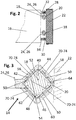
- Fig. 2 shows in one embodiment car guides 32, 34 of the elevator car 16 co-acting with guide rails 28 running vertically along the shaft wall 22 of Fig. 1 .
- the shaft wall 22 comprises two parallel guide rails 28, 30 co-acting with corresponding car guides 32, 34.
- Each car guide 32, 34 has a set of guide rollers co-acting with the car guide rails 28, 30.
- the corresponding guide system 28, 30, 32, 34 is configured to keep the car 16 horizontally in connection with the shaft wall 22 as these both car guide rails 28, 30 are the only guide rails of the elevator car 16 in the shaft 12.
- In connection with each elevator car there are four car brakes as well as for movers.
- the vertical stator beam 18 comprises a metal support structure 40 with a square cross-section.
- the support structure 40 carries a metal stator rod 50 comprising stator teeth 52, which form the four side faces 42, 44, 46, 48 of the stator beam 18.
- stator rods (or bars) 50 with the stator teeth 52 forms a stator of the linear motor 14 so that the stator beam 18 shown in Fig. 3 comprises four stators.
- the stator teeth 52 co-act with windings 74, 76 ( Fig. 4 ) and mover irons 70,72 and permanent magnets 71 located along counter-faces 54 in the four arms 56, 58, 60, 62 of the C-type profile of the mover 24, 26.
- This C-type profile of the mover surrounds the stator beam 18 but leaves an opening 64 for the adaption of the fastening elements 20, as the mover 24, 26 travels along the shaft 12.
- stator rods 50 on all four side faces 42, 44, 46, 48 have the same pitch d.
- first and third side face 42, 46 of the stator beam also have an identical teeth position in vertical direction whereas the second and fourth side face 44, 48 have the same pitch but the teeth position is vertically offset with respect to the stator teeth 52 on the first and third side face 42, 46 by a 1 ⁇ 4 pitch.
- Fig. 4 shows an elevator 100 having two elevator shafts 102, 104 which are connected by an upper horizontal passage 106 at the top end of both shafts 102, 104 as well as a lower horizontal passage 108 at the bottom end of both elevator shafts 102, 104.
- the both elevator shafts 102, 104 with the upper and lower horizontal passage 106, 108 form a closed loop whereby the movement of the elevator cars 16a-16d is only allowed in one direction according to the arrows shown in the figure.
- each shaft 102, 104 may comprise preferably two, three or four parallel stator beams 18, 114.
- the figure shows landing doors 110 located in the first elevator shaft 102 as well as in the second elevator shaft 104.
- the cars 16a-16d are horizontally moved in the horizontal passages 106, 108 in a not specified manner by horizontal moving mechanisms.
- Both elevator shafts are cut out along the cutting line 112 for clarity reasons, as normally this concept is preferably designed for high-rise elevators having 20 floors or more. Accordingly, the two shafts 102, 104 are able to accommodate a much larger number of elevator cars than the four cars 16a-16d shown in the figure. Each car 16a-16d is able to move largely independent of the others within the two shafts 102, 104 except the fact that collisions between cars have to be avoided. By the fact that in the first elevator shaft 102 the elevator cars 16a-16d only drive downwards and in the second elevator shaft 104 only drive upwards, the probability of mutual affection is decreased.
- Fig. 6 shows an elevator 200 comprising two elevator shafts 202, 204 which are preferably no longer separated by shaft walls.
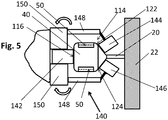
- the vertical stator beams 114 correspond to the stator beams shown in Fig. 5 and the car guides 140 of the cars 16a-16d of Fig. 6 correspond to the car guides 140 shown in Fig. 5 .
- horizontal guide tracks (see also Fig. 6 ) 206 are extending horizontally along horizontal passages 208 located between the two elevator shafts 202, 204 whereby the term "elevator shaft" in this connection designates the vertical moving paths of the elevator cars 16a-16d in this elevator 200.
- the two remaining shaft walls 22 which are opposite to the horizontal passages 208 do not only comprise the vertical stator beams but also the vertical bus bars which are not shown for clarity reasons, as Fig. 6 focuses on the horizontal moving mechanism 205.
- the horizontal moving mechanism 205 comprises the horizontal guide tracks 206 on each elevator floor and a horizontal moving means 210 located on top of each elevator car 16a-16d.
- the horizontal moving means 210 of the elevator car comprises support rollers 212 which can be moved between a retracted position and an operational position wherein the support rollers 212 run on the horizontal guide tracks 206.
- the moving pattern of the elevator cars in the elevator car 200 corresponds to that of Fig. 4 which means that in the first elevator shaft 202, the elevators all move in the same direction, i.e. upwards, whereas in the second elevator shaft 204 all elevator cars 16a-16d move downwards. Therefore, also in this elevator 200, a kind of circular movement is achieved whereby the circular movement can be shortened as the elevator cars can travel from one elevator shaft 202, 204 into the other at each elevator floor via the horizontal moving mechanism 205 comprising the horizontal guide tracks 206 and the horizontal moving means 210 of the elevator car.
- the elevator car 16a-16d comprises a car control 214 having a wireless transmission means 216 for wireless communication with the elevator control. Furthermore, the elevator car 16a-16d comprises a power source 218, preferably an accumulator, which feeds the movers 24, 26; 126 of the elevator car 16, 16a-16d as well as all other electrical components connected to the elevator car.
- the horizontal moving means 210 comprises of four roller arrangements 220. Each roller arrangement 220 comprises a mounting base 222 on which a support arm 224 is pivotally hinged.
- the support arm 224 can be moved between a retracted position (shown on the left side of the figure) and an operational position (shown on the right side) in which the support roller 212 runs on top of the horizontal guide track 206.
- a drive member 226 Connected with the support arm 224 is a drive member 226 on which the support roller is supported.
- the drive member comprises an electric motor which is configured to rotate the support roller 212 on the horizontal guide track 206. It is self-evident that any operation of the pivot mechanism in the mounting base 222 can be prohibited when the support roller is currently positioned in the retracted position shown on the left side as well as in the operational position of the support roller 212 on the horizontal guide track 206. Therefore, a locking mechanism (not shown) is preferably provided to lock the corresponding positions.
- Fig. 8 shows an embodiment of the invention with an elevator (motor) control 230, preferably comprising an emergency stop circuit 232 backed-up by a backup power supply 234, preferably a battery.
- elevator (motor) control 230 preferably comprising an emergency stop circuit 232 backed-up by a backup power supply 234, preferably a battery.
- the elevator control 230 selectively energizes the coils of the car brakes 301, 302 to open or apply the car brakes. When applied, the car brakes 301, 302 engage against guide rails (not shown in fig. 8 ).
- the elevator control 230 also energizes the windings 74, 76 of the movers 24, 26 on one hand as to regulate the air gap between stator side faces 42 - 48 and counterfaces 54 of the mover 24, 26. On the other hand the elevator control energizes the windings 74, 76 as to move the car along the stator beams 18.
- the elevator control 230 energizes the windings 74, 76 as to regulate the air gap and only afterwards starts to energize the windings in a way as to move the car.
- the car brakes 301, 302 are applied as to decelerate the car 16 to stop and hold the car at standstill.
- the elevator control 230 comprises a braking test circuit 236 which in a braking test mode (when the car brakes 301, 302 are applied (car is stopped) and the brake interface is active) energizes the movers, and opens only one car brake such that the other car brake is still engaged. Via decreasing upwards propulsion force of the movers 24 the force acting on the engaged car brake increases due to gravity until the engaged car brake is no longer able to withstand the force, which is when the car starts moving.
- the emergency stop circuit 232 of the elevator control ensures safe deceleration and stop of the elevator car in all abnormal operation conditions of the elevator, particularly in case of an AC power failure.
- the elevator control immediately switches the power supply for the mover windings 74, 76 to the backup power supply 234 and continues current supply to magnetizing coils of the car brakes from the backup power supply.
- the elevator control 230 decelerates the car to stop either with a defined deceleration and/or within a defined stopping distance.
- car brakes 301, 302 are applied so that the car 16 is safely supported on the stator beams 18.
- the car might be driven in an emergency car ride to the next floor in driving direction so that the passengers may leave the car.
- This option is only provided for emergency situations in which the elevator car is allowed to drive to the next floor, e.g. in case of a power failure of AC mains.
- the elevator control 230 may comprise a battery monitoring circuit 238 for the backup power supply 234 to ensure functionality of the backup power supply in emergency situations.
- This battery monitoring circuit may issue a battery change signal if the battery performance decreases.
- Fig. 9 shows a schematic diagram of the checking of the functional state of the car brake, formed by the brake interface 51, 55.
- the brake test circuit 236 applies one of the car brakes while the other ones remain open. Upwards propulsion force is provided by supplying current to the windings of the movers 24. In step 242 the current flow of the windings 74, 76 generating upwards propulsion force is decreased.
- the first deciding step 244 it is checked whether the elevator car starts moving which information is obtained via position sensors and/or velocity sensors and/or acceleration sensors of the elevator. If the elevator does not start moving the process loops back to step 242 wherein the current flow generating upwards propulsion force is further decreased. If the elevator starts moving the first deciding step 244 branches to log step 246 wherein the critical current flow when the car began moving is recorded. In the second deciding step 248 the critical current flow is compared with a first threshold value. If the critical current flow is below this first threshold value the process moves to the third deciding step 252. If the critical current flow value is above the first threshold value the elevator is taken out of service in step 250 and a notice is given to a remote maintenance center, possibly comprising the critical current flow value and optionally the first threshold value.
- the critical current flow value is compared with a second threshold value which is lower than the first threshold value.
- a maintenance signal is issued to a remote maintenance center in step 254. This signal may comprise information about the critical current flow value as well as about one or both threshold values.
- the braking mode is stopped in termination step 256 whereafter the normal operating mode of the elevator is started.
- the retracted and operational position of the support roller 212 is controlled in synchronization with the initiation and releasing of the contact between the movers 126 and the corresponding vertical stator beams 114. Via this arrangement, it is ensured that the car is always supported in vertical direction either by the force of the mover 126 on the vertical stator beam 114 or by the support of the support rollers 212 on the horizontal guide tracks 206.
Landscapes
- Engineering & Computer Science (AREA)
- Automation & Control Theory (AREA)
- Mechanical Engineering (AREA)
- Structural Engineering (AREA)
- Computer Networks & Wireless Communication (AREA)
- Power Engineering (AREA)
- Electromagnetism (AREA)
- Physics & Mathematics (AREA)
- Civil Engineering (AREA)
- Chemical & Material Sciences (AREA)
- Combustion & Propulsion (AREA)
- Types And Forms Of Lifts (AREA)
- Maintenance And Inspection Apparatuses For Elevators (AREA)
- Elevator Control (AREA)
- Cage And Drive Apparatuses For Elevators (AREA)
Abstract
Description
- The present invention relates to an elevator comprising an elevator car and one or more guide rails to define a path of movement of an elevator car.
- The elevator may comprise an electric linear motor as it is disclosed in the
WO 2016/207136 A1 . The linear motor comprises a linear stator designed to be located in a fixed correlation to an environment, particularly a building. The elevator further comprises at least one mover designed for connection with an elevator car to be moved and co-acting with the stator to move the car. The motor comprises a stator beam supporting said at least one stator, which stator beam has at least one side face carrying ferromagnetic poles of said stator spaced apart by a pitch. Accordingly, the mover comprises at least one counter-face facing said side face of the stator beam, in which counter-face electromagnetic components of the mover are arranged to co-act with the ferromagnetic poles of the stator beam. During the operation of the elevator, particularly when the elevator car is running, the magnetic field of the electromagnetic components of the mover keep the counter-face of the mover spaced apart from the side face of the stator by an air gap a. This new technology has proved to be quite efficient, particularly in elevator constructions in which the travelling of the car is not only vertical. For this reason, the general design of elevator brakes which were always based on the braking of the traction sheave driving an elevator car via the hoisting ropes is not applicable in this concept. Furthermore, if hoisting ropes are very long, as it is the case with high-rise elevators, movement of the elevator car due to sway or stretch of the hoisting ropes may cause unwanted movement of elevator car. For these reasons, among others, car brakes have been provided in connection with elevator car. By engaging the car brakes against guide rails, elevator car can be hold at standstill or movement of elevator car can be braked. - To improve elevator safety, by means of this invention a method for monitoring the operating condition of car brakes can be realized. The object is solved with an elevator according to claim 1. Advantageous embodiments of the invention are subject matter of the corresponding dependent claims. Preferred embodiments of the invention are also subject matter of the description and of the drawings.
- A first aspect of the invention is an elevator comprising an elevator car and one or more guide rails to define the path of movement of an elevator car, the elevator further comprising an electric linear motor comprising at least one linear stator designed to be located in a fixed correlation to an environment, particularly building, and at least one mover designed for connection with an elevator car to be moved and co-acting with the stator to move the car. Motor comprises a stator beam supporting said at least one stator, which stator beam has at least one side face carrying ferromagnetic teeth of said stator spaced apart by a pitch, and which mover comprises at least one counter-face facing said side face(s) of the stator beam, the motor further comprising electro-magnetic components being mounted to the mover and / or to the stator to provide propulsion force to the elevator car, wherein the elevator comprises two or more elevator car brakes mounted to an elevator car, each of the car brakes comprising an actuator to control the car brake and each of the car brakes fitted to selectively engage against a guide rail of an elevator car to stop movement of an elevator car or to open to enable movement of an elevator car. One suitable car brake is represented in
EP 0856485 A1 . It has as an actuator an electromagnet 15 withcoil 16 and magnetic core to control opening / engaging of the brake against guide rail 2. When the car brake is engaged, elevator car is kept at its level via mere friction of braking surfaces of the car brake against the guide rail. - According to an embodiment, the elevator comprises a backup-power supply and an emergency stop circuit, which emergency stop circuit is connected to a position and/or velocity and/or acceleration sensor of the elevator, and which emergency stop circuit is configured to adjust the energization of the electromagnetic components of the linear motor and / or the actuators of one or more car brakes depending on the signal of the above sensor(s). Via this means it can be ensured that in any case of power off, the elevator does not suddenly stop but via the backup power supply, the emergency stop circuit ensures deceleration of the elevator car within allowed tolerances until the stop of the elevator car. This measure ensures the safety of the passengers in any case of power failure of the AC mains.
- According to an embodiment, the emergency stop circuit is configured to adjust the energization of the electromagnetic components and / or the actuators of one or more car brakes such that the car stops within a defined stopping distance.
- According to an embodiment, the elevator control comprises a brake test circuit configured to operate in a brake test mode wherein only one actuator is de-energized to apply elevator car brake when the car is not moving, particularly if it is stopping at a floor.
- According to an embodiment, associated with each car brake there is a load sensor, such as a strain gauge, arranged between the car and the car brake to measure total weight of car.
- Therewith, a method for testing the operating condition of an elevator car brake in an elevator can be realized. The method comprises the succession of following steps: an empty car is kept at standstill by providing a driving force upwards with the at least one mover mounted to the elevator car. One of the car brakes is applied while the others are kept open. The driving current of the at least one mover is gradually decreased, and movement of elevator car is observed. When movement of elevator car is detected, the total driving current of the at least one mover at the moment movement started is recorded, and the recorded current is compared to a reference value. If the recorded current is higher than the reference value, safety measures with the elevator are performed. Applying of the car brake means that, by controlling the actuator, brake is engaged against the guide rail to brake movement of the car / hold the car at level.
- At least, a method for testing the operating condition of an elevator car brake in an elevator according to the first aspect of the invention can be realized, wherein the elevator further comprises associated with each of the car brakes a load sensor, such as a strain gauge, which is arranged between the car and the car brake to measure total weight of car, the method comprising the succession of following steps: one of the car brakes is applied while the others are kept open, and an empty car is kept at standstill by providing a driving force upwards with the at least one mover, such that the load sensor of the applied car brake indicates preferably zero weight. The driving current of the at least one mover is gradually decreased, and the movement of elevator car is observed, and when the movement of the elevator car is detected, the reading of the load sensor of the applied car brake at the moment movement started is recorded, and the recorded reading is compared to a reference value. If the recorded reading of the load sensor is lower than the reference value, safety measures with the elevator are performed. According to a refinement, as the driving current of the at least one mover is gradually decreased, at the same time the reading of the load sensor of the engaged car brake is observed and compared to said driving current, to ensure that decreasing of the driving current causes reading of the load sensor to increase with a predefined pattern. This means that correct operation of the load sensor can be monitored.
- The car brakes are preferably tested one at a time, such that after one car brake has been tested, it is opened and another one is applied and then the testing method according to the second or third aspect of the invention is repeated.
- According to an embodiment, brake test mode is performed when the car is stopping at a floor.
- According to an embodiment, the safety measures comprises at least one of the following steps: sending a log report with the energization when the car starts moving to a maintenance center, sending a log report with the threshold value which the energization was compared to a maintenance center, putting the elevator out of service, issuing a maintenance request.
- Preferably, this backup-power supply is a battery, but it also may be a series of super-capacitors and/or second independent power supply network.
- In case a battery is used as a backup-power supply, the elevator preferably comprises a battery monitoring circuit for monitoring the function or status of the battery. By this means it can be ensured that the functional status of the battery is such that the elevator stop circuit is always able to ensure a smooth elevator stop drive in case of power off as mentioned above.
- Preferably, on this behalf, the current of the movers is compared with at least one threshold value, which allows the differentiation of brake in order/ brake has to be maintained or is not working in a sufficient manner to provided required safety. Preferably two threshold values are provided for comparison with the critical current value, so that three different operational status of the brake can be identified: brake in order, brake needs maintenance and brake is not safe as mentioned above in connection with the description of the inventive elevator.
- Preferably, the upwards propulsion force of each mover is adjusted to a value corresponding to a test force F defined as follows:

- F is required test force for testing one brake at a time
- M is weight of empty elevator car in kilograms
- L is rated maximum load of elevator car in kilograms
- g is gravity constant 9,81
- N is number of brakes in one car.
- Example: N = 4 brakes, M = 800 Kg, L = 1000 Kg, then
F = 1800Kg∗9,81/3 = 5886 N. - This also fulfils the requirement that all N brakes must hold together (125% ∗ L+M)g
- In the above example the requirement is: (125%∗1000Kg+800Kg)9,81 = 20110 N. On the other hand, it has already been tested that 4 brakes can perform: 4∗5886 N = 23544 N which is sufficient.
- If this test force does not lead to the car starts moving, the brake test is terminated and the brake is evaluated as being in order.
- In some embodiments, it may be also necessary to not only decrease the upwards propulsion force during testing but also to further increase it in the opposite direction, e.g. in the downwards direction or otherwise in the direction of interaction of gravity, to increase the test force to a magnitude required for testing.
- It is clear for the skilled person that the above-mentioned embodiments can be combined with each other arbitrarily. It has been mentioned that preferably an elevator car is supported with two stator beams and two vertically spaced apart movers which means four movers per elevator car. Preferably the elevator car is supported by at least two car brakes, most preferably by at least 4 car brakes. This number of movers / car brakes per elevator car may differ from this value. If the stator beam is large enough as well as the mover is large and long enough, even one stator beam and one mover per elevator car may be sufficient to support the car and to implement the necessary brake interface. If there are only two car brakes per elevator car, they are preferably associated with separate guide rails to enhance reliability and safety.
- Following terms are used as synonyms: critical energization value - energization value when the car starts moving in the brake test mode; elevator control - elevator motor control; car - elevator car; brake interface - elevator brake
- The invention is hereinafter described via an example with the aid of the enclosed drawings.
- The invention is now described hereinafter with respect to the enclosed drawing. In this drawing
- Fig. 1
- shows a side view of an elevator shaft with a linear elevator motor comprising two parallel stator beams,
- Fig. 2
- shows a horizontal cross-section of the parts of the elevator motor and the guide rails in the area between the elevator car and the shaft wall of
Fig. 1 , - Fig. 3
- shows a cross-section through a stator beam and a mover of
Fig. 2 , - Fig. 4
- shows a side view of an elevator having two elevator shafts which are connected at their upper and lower ends with horizontal passages,
- Fig. 5
- shows a horizontal cross-section of the connecting part between the shaft wall and an elevator car at the car guide position, showing a guide element of the elevator car with two pivoted guide rollers which guide element is running along guide surfaces of the stator beam of
Fig. 7 , - Fig. 6
- shows a schematic side view of an elevator system having two elevator shafts which are connected with horizontal passages at each elevator floor whereby the landing doors are located in the area of the horizontal passages between each shaft,
- Fig. 7
- shows a horizontal moving mechanism with shaft-side horizontal guide tracks and a car-side horizontal moving means comprising rollers co-acting with the horizontal guide tracks,
- Fig. 8
- shows a schematic view of the elevator control controlling movers in a brake test mode,
- Fig. 9
- shows a diagram regarding the use of the critical energization for deriving brake status information/perform failure measures.
- It is emphasized that identical parts or parts with the same functionality are designated by the same reference numbers in all figures.
-
Fig. 1 shows anelevator 10 comprising anelevator shaft 12 wherein anelevator car 16 moves up and down as an element to be moved, along a path of movement defined by two guide rails. Theelevator 10 has alinear elevator motor 14. Thelinear elevator motor 14 comprises stators 50 (seeFig. 3 ) located in a side face of astator beam 18 which is mounted withfastening elements 20 to ashaft wall 22 of theelevator shaft 12. In this example theelevator 10 has two parallel stator beams 18, which can be seen inFig. 2 . - The
elevator car 16 comprises twomovers lower mover 24 is located in the lower half of the elevator car whereas theupper mover 26 is located in the upper half of the elevator car. These twomovers Fig. 4 ) which co-act withstator poles 52 located in the side faces of thestator beam 18, formed by stator teeth. Accordingly, the elevator car travels upwards and downwards via corresponding control of bothmovers - Of course, the elevator car has a corresponding set of two
movers vertical stator beam 18 so that theelevator car 16 has in total four movers, twolower movers 24 and twoupper movers 26 to co-act with two stator beams 18. - Of course, each
stator beam 18 may have one orseveral stators 50 as it is shown inFigs. 2 and 3 . - In some other embodiments, the windings may be provided in the stator and mover has permanents magnets. In this case, the propulsion force for the movers is provided by supplying current to the stator coils.
-
Fig. 2 shows in one embodiment car guides 32, 34 of theelevator car 16 co-acting withguide rails 28 running vertically along theshaft wall 22 ofFig. 1 . Theshaft wall 22 comprises twoparallel guide rails car guide car guide rails car guide rails corresponding guide system car 16 horizontally in connection with theshaft wall 22 as these bothcar guide rails elevator car 16 in theshaft 12. In connection with each elevator car there are four car brakes as well as for movers. Two of the car brakes are fitted to engage same guide rail (car brakes, which are not shown infig. 2 , are the same type as disclosed inEP 0856485 A1 ). The vertical stator beams 18 as well as themovers elevator car 16 are shown in more detail inFig. 3 . Generally, guide rails with a round cross-section may be used which are surrounded by rollers of the car guide, thereby fixing the car horizontally in connection with the guide rail. - According to
Fig. 3 thevertical stator beam 18 comprises ametal support structure 40 with a square cross-section. On each side thesupport structure 40 carries ametal stator rod 50 comprisingstator teeth 52, which form the four side faces 42, 44, 46, 48 of thestator beam 18. Each of these stator rods (or bars) 50 with thestator teeth 52 forms a stator of thelinear motor 14 so that thestator beam 18 shown inFig. 3 comprises four stators. Thestator teeth 52 co-act with windings 74, 76 (Fig. 4 ) and mover irons 70,72 and permanent magnets 71 located along counter-faces 54 in the fourarms mover stator beam 18 but leaves anopening 64 for the adaption of thefastening elements 20, as themover shaft 12. - The
stator rods 50 on all four side faces 42, 44, 46, 48 have the same pitch d. Anyway, the first andthird side face fourth side face stator teeth 52 on the first andthird side face - Via this arrangement, it is ensured that on one hand, the horizontal forces between the
stators 50 on opposite sides eliminate each other whereas the vertical offset of the pitches of the side faces oriented rectangular leads to a better efficiency and a smoother run of the elevator motor, as a moving step of such amotor 14 is a half pitch. By the fact that fourstators 50 are located within thestator beam 18 the force generated between themovers stator beam 18 is multiplied by four, thereby achieving less horizontal ripples and a smoother movement of themovers vertical stator beam 18. -
Fig. 4 shows anelevator 100 having twoelevator shafts horizontal passage 106 at the top end of bothshafts horizontal passage 108 at the bottom end of bothelevator shafts elevator shafts horizontal passage elevator cars 16a-16d is only allowed in one direction according to the arrows shown in the figure. By this measure it is ensured that cars run only in one direction in each of the shafts which lead to a higher transport capacity and to an easier control of the cars in the shaft. - In both
elevator shafts Figs. 4 are located which co-act withmovers elevator cars 16a-16d. Eachshaft doors 110 located in thefirst elevator shaft 102 as well as in thesecond elevator shaft 104. Thecars 16a-16d are horizontally moved in thehorizontal passages - Both elevator shafts are cut out along the cutting line 112 for clarity reasons, as normally this concept is preferably designed for high-rise elevators having 20 floors or more. Accordingly, the two
shafts cars 16a-16d shown in the figure. Eachcar 16a-16d is able to move largely independent of the others within the twoshafts first elevator shaft 102 theelevator cars 16a-16d only drive downwards and in thesecond elevator shaft 104 only drive upwards, the probability of mutual affection is decreased. Furthermore, by this circular moving scheme, the transport capacity of both shafts is drastically increased on one hand because now the two elevator shafts may comprise much more elevator cars than in conventional systems and on the other hand, because in each elevator shaft, all elevator cars only move in the same direction, avoiding counter-movements of cars which reduce an economic shaft use and necessitate extensive anti-collision control. -
Fig. 6 shows anelevator 200 comprising twoelevator shafts Fig. 5 and the car guides 140 of thecars 16a-16d ofFig. 6 correspond to the car guides 140 shown inFig. 5 . InFig. 6 , at each elevator floor, horizontal guide tracks (see alsoFig. 6 ) 206 are extending horizontally alonghorizontal passages 208 located between the twoelevator shafts elevator cars 16a-16d in thiselevator 200. The two remainingshaft walls 22 which are opposite to thehorizontal passages 208 do not only comprise the vertical stator beams but also the vertical bus bars which are not shown for clarity reasons, asFig. 6 focuses on thehorizontal moving mechanism 205. Thehorizontal moving mechanism 205 comprises the horizontal guide tracks 206 on each elevator floor and a horizontal moving means 210 located on top of eachelevator car 16a-16d. The horizontal moving means 210 of the elevator car comprisessupport rollers 212 which can be moved between a retracted position and an operational position wherein thesupport rollers 212 run on the horizontal guide tracks 206. - The moving pattern of the elevator cars in the
elevator car 200 corresponds to that ofFig. 4 which means that in thefirst elevator shaft 202, the elevators all move in the same direction, i.e. upwards, whereas in thesecond elevator shaft 204 allelevator cars 16a-16d move downwards. Therefore, also in thiselevator 200, a kind of circular movement is achieved whereby the circular movement can be shortened as the elevator cars can travel from oneelevator shaft horizontal moving mechanism 205 comprising the horizontal guide tracks 206 and the horizontal moving means 210 of the elevator car. - The function of the
horizontal moving mechanism 205 based on the interaction between the horizontal guide tracks 206 and the horizontal moving means 210 of theelevator car 16a-16d is described in more detail with respect toFig. 7 . Theelevator car 16a-16d comprises acar control 214 having a wireless transmission means 216 for wireless communication with the elevator control. Furthermore, theelevator car 16a-16d comprises apower source 218, preferably an accumulator, which feeds themovers elevator car roller arrangements 220. Eachroller arrangement 220 comprises a mountingbase 222 on which asupport arm 224 is pivotally hinged. Thesupport arm 224 can be moved between a retracted position (shown on the left side of the figure) and an operational position (shown on the right side) in which thesupport roller 212 runs on top of thehorizontal guide track 206. Connected with thesupport arm 224 is adrive member 226 on which the support roller is supported. The drive member comprises an electric motor which is configured to rotate thesupport roller 212 on thehorizontal guide track 206. It is self-evident that any operation of the pivot mechanism in the mountingbase 222 can be prohibited when the support roller is currently positioned in the retracted position shown on the left side as well as in the operational position of thesupport roller 212 on thehorizontal guide track 206. Therefore, a locking mechanism (not shown) is preferably provided to lock the corresponding positions. -
Fig. 8 shows an embodiment of the invention with an elevator (motor)control 230, preferably comprising anemergency stop circuit 232 backed-up by abackup power supply 234, preferably a battery. - The
elevator control 230 selectively energizes the coils of thecar brakes car brakes fig. 8 ). Theelevator control 230 also energizes the windings 74, 76 of themovers counterfaces 54 of themover - Before the car begins to move the
elevator control 230 energizes the windings 74, 76 as to regulate the air gap and only afterwards starts to energize the windings in a way as to move the car. In contrast when the car shall stop at a floor or in emergency cases thecar brakes car 16 to stop and hold the car at standstill. - The
elevator control 230 comprises abraking test circuit 236 which in a braking test mode (when thecar brakes movers 24 the force acting on the engaged car brake increases due to gravity until the engaged car brake is no longer able to withstand the force, which is when the car starts moving. - The
emergency stop circuit 232 of the elevator control ensures safe deceleration and stop of the elevator car in all abnormal operation conditions of the elevator, particularly in case of an AC power failure. In this case the elevator control immediately switches the power supply for the mover windings 74, 76 to thebackup power supply 234 and continues current supply to magnetizing coils of the car brakes from the backup power supply. Thereby theelevator control 230 decelerates the car to stop either with a defined deceleration and/or within a defined stopping distance. After car stop the mover windings 74, 76 are de-energized andcar brakes car 16 is safely supported on the stator beams 18. Preferably the car might be driven in an emergency car ride to the next floor in driving direction so that the passengers may leave the car. This option is only provided for emergency situations in which the elevator car is allowed to drive to the next floor, e.g. in case of a power failure of AC mains. - Optionally the
elevator control 230 may comprise abattery monitoring circuit 238 for thebackup power supply 234 to ensure functionality of the backup power supply in emergency situations. This battery monitoring circuit may issue a battery change signal if the battery performance decreases. -
Fig. 9 shows a schematic diagram of the checking of the functional state of the car brake, formed by the brake interface 51, 55. At thestart 240 of the brake test mode thebrake test circuit 236 applies one of the car brakes while the other ones remain open. Upwards propulsion force is provided by supplying current to the windings of themovers 24. Instep 242 the current flow of the windings 74, 76 generating upwards propulsion force is decreased. - In the first deciding
step 244 it is checked whether the elevator car starts moving which information is obtained via position sensors and/or velocity sensors and/or acceleration sensors of the elevator. If the elevator does not start moving the process loops back to step 242 wherein the current flow generating upwards propulsion force is further decreased. If the elevator starts moving the first decidingstep 244 branches to logstep 246 wherein the critical current flow when the car began moving is recorded. In the second decidingstep 248 the critical current flow is compared with a first threshold value. If the critical current flow is below this first threshold value the process moves to the third decidingstep 252. If the critical current flow value is above the first threshold value the elevator is taken out of service instep 250 and a notice is given to a remote maintenance center, possibly comprising the critical current flow value and optionally the first threshold value. - In the third deciding
step 252 the critical current flow value is compared with a second threshold value which is lower than the first threshold value. When the critical current flow (current) is above the second threshold value a maintenance signal is issued to a remote maintenance center instep 254. This signal may comprise information about the critical current flow value as well as about one or both threshold values.
The braking mode is stopped intermination step 256 whereafter the normal operating mode of the elevator is started. - It is clear for the skilled person that the retracted and operational position of the
support roller 212 is controlled in synchronization with the initiation and releasing of the contact between themovers 126 and the corresponding vertical stator beams 114. Via this arrangement, it is ensured that the car is always supported in vertical direction either by the force of themover 126 on thevertical stator beam 114 or by the support of thesupport rollers 212 on the horizontal guide tracks 206. - Thus, high safety of the elevator car may be maintained corresponding to a gripping device.
- The invention can be carried out within the scope of the appended patent claims. Thus, the above-mentioned embodiments should not be understood as delimiting the invention.
-
- 10
- elevator
- 12
- elevator shaft
- 14
- elevator motor
- 16
- elevator car
- 18
- stator beam
- 20
- fastening elements
- 22
- shaft wall /shaft side
- 24
- lower mover
- 26
- upper mover
- 28
- first guide rail
- 30
- second guide rail
- 32
- first car guide
- 34
- second car guide
- 40
- support structure
- 42
- first side face
- 44
- second side face
- 46
- third side face
- 48
- fourth side face
- 50
- stator / stator rod
- 51
- stator brake surface - stator braking pad
- 52
- stator teeth
- 53
- teeth gaps
- 54
- counter face of mover
- 55
- mover brake surface - mover braking pad
- 56
- first arm of C-profile mover
- 58
- second arm of C-profile mover
- 60
- third arm of C-profile mover
- 62
- fourth arm of C-profile mover
- 70
- first mover iron
- 71
- permanent magnet
- 72
- second mover iron
- 74
- first winding
- 76
- second winding
- 100
- elevator (second embodiment)
- 102
- first elevator shaft
- 104
- second elevator shaft
- 106
- upper horizontal passage
- 108
- lower horizontal passage
- 110
- landing door
- 114
- stator beam (second embodiment)
- 116
- first side face (first guide face)
- 118
- second side face
- 120
- third side face
- 122
- fourth side face (second guide face)
- 124
- fifth side face (third guide face)
- 126
- mover (second embodiment)
- 128
- mounting element
- 130
- bus bar
- 132
- connector rails
- 134
- contactor
- 136
- spring support
- 140
- car guide (second embodiment)
- 142
- first guide roller, at the car side
- 144
- second guide roller, at the shaft wall side
- 146
- third guide roller, at the shaft wall side
- 148
- pivot arm
- 150
- pivoting mechanism
- 200
- elevator (third embodiment)
- 202
- first elevator shaft
- 204
- second elevator shaft
- 205
- horizontal moving mechanism
- 206
- horizontal guide track
- 208
- horizontal passage
- 210
- horizontal moving means mounted to the elevator car
- 212
- support roller
- 214
- car control
- 216
- wireless transmission means
- 218
- power supply
- 220
- roller arrangement
- 222
- mounting base
- 224
- support arm
- 226
- drive member
- 230
- elevator control
- 232
- emergency stop circuit
- 234
- backup power supply
- 236
- brake test circuit
- 238
- battery monitoring circuit
- 240
- start of brake test mode - a part of the movers is energized, a part is de-energized
- 242
- increasing the energization/current of the energized mover
- 244
- first deciding step - car starts moving?
- 246
- recording the critical energization/current
- 248
- second deciding step - first threshold value passed by critical energization value?
- 250
- elevator taken out of service
- 252
- third deciding step - second threshold value passed by critical energization value?
- 254
- maintenance requested for the elevator
- 256
- end of the brake test mode
Claims (7)
- Elevator comprising an elevator car and one or more guide rails to define a path of movement of the elevator car, the elevator further comprising an electric linear motor (14) comprising at least one linear stator (50) designed to be located in a fixed correlation to an environment, particularly building, and at least one mover (24, 26; 126) designed for connection with the elevator car to be moved (16; 16a-16d) and co-acting with the stator to move the car,
which motor comprises a stator beam (18; 114) supporting said at least one stator (50), which stator beam has at least one side face (42-48; 116-124) carrying ferromagnetic teeth (52) of said stator spaced apart by a pitch (d), and which mover (24, 26; 126) comprises at least one counter-face (54) facing said side face(s) of the stator beam, the motor further comprising electro-magnetic components (70, 71, 72, 74, 76) being mounted to the mover (24, 26; 126) and / or to the stator (50) to provide propulsion force to the elevator car (16; 16a-16d), characterized in that elevator comprises two or more elevator car brakes mounted to the elevator car, each of the car brakes comprising an actuator to control the car brake and each of the car brakes fitted to selectively engage against a guide rail of an elevator car to stop movement of the elevator car or to open to enable movement of the elevator car. - Elevator according to claim 1, characterized in that the elevator comprises a backup-power supply (234) and an emergency stop circuit (232), which emergency stop circuit is connected to a position and/or velocity and/or acceleration sensor of the elevator, and which emergency stop circuit (232) is configured to adjust the energization of the electromagnetic components (74, 76) and / or the actuators of one or more car brakes depending on the signal of the above sensor(s).
- Elevator according to claim 2, wherein the backup-power supply (234) is a battery.
- Elevator according to claim 3, comprising a battery monitoring circuit (238) for monitoring the functional status of the battery.
- Elevator according to one of claims 2 to 4, characterized in that the emergency stop circuit (232) is configured to adjust the energization of the electromagnetic components (74, 76) and / or the actuators of one or more car brakes such that the car (16) stops within a defined stopping distance.
- Elevator according to one of the preceding claims, wherein the elevator control (230) comprises a brake test circuit (236) configured to operate in a brake test mode wherein only one actuator is de-energized to apply elevator car brake when the car (16) is not moving, particularly if it is stopping at a floor.
- Elevator according to any of preceding claims, wherein associated with each car brake (24, 26; 126) there is a load sensor, such as a strain gauge, arranged between the car and the car brake (24, 26; 126) to measure total weight of car.
Applications Claiming Priority (3)
| Application Number | Priority Date | Filing Date | Title |
|---|---|---|---|
| EP17158966.6A EP3369686B1 (en) | 2017-03-02 | 2017-03-02 | Elevator comprising an electric linear motor |
| EP18713793.0A EP3589573A2 (en) | 2017-03-02 | 2018-02-23 | Elevator with an electrical linear motor |
| PCT/EP2018/054476 WO2018158144A2 (en) | 2017-03-02 | 2018-02-23 | Elevator |
Related Parent Applications (1)
| Application Number | Title | Priority Date | Filing Date |
|---|---|---|---|
| EP18713793.0A Division EP3589573A2 (en) | 2017-03-02 | 2018-02-23 | Elevator with an electrical linear motor |
Publications (1)
| Publication Number | Publication Date |
|---|---|
| EP3674247A1 true EP3674247A1 (en) | 2020-07-01 |
Family
ID=58213029
Family Applications (3)
| Application Number | Title | Priority Date | Filing Date |
|---|---|---|---|
| EP17158966.6A Not-in-force EP3369686B1 (en) | 2017-03-02 | 2017-03-02 | Elevator comprising an electric linear motor |
| EP20157298.9A Withdrawn EP3674247A1 (en) | 2017-03-02 | 2018-02-23 | Elevator with an electrical linear motor |
| EP18713793.0A Withdrawn EP3589573A2 (en) | 2017-03-02 | 2018-02-23 | Elevator with an electrical linear motor |
Family Applications Before (1)
| Application Number | Title | Priority Date | Filing Date |
|---|---|---|---|
| EP17158966.6A Not-in-force EP3369686B1 (en) | 2017-03-02 | 2017-03-02 | Elevator comprising an electric linear motor |
Family Applications After (1)
| Application Number | Title | Priority Date | Filing Date |
|---|---|---|---|
| EP18713793.0A Withdrawn EP3589573A2 (en) | 2017-03-02 | 2018-02-23 | Elevator with an electrical linear motor |
Country Status (5)
| Country | Link |
|---|---|
| US (2) | US11084690B2 (en) |
| EP (3) | EP3369686B1 (en) |
| JP (1) | JP2018145011A (en) |
| CN (2) | CN110382394B (en) |
| WO (1) | WO2018158144A2 (en) |
Families Citing this family (19)
| Publication number | Priority date | Publication date | Assignee | Title |
|---|---|---|---|---|
| CN107207191A (en) * | 2015-02-04 | 2017-09-26 | 奥的斯电梯公司 | Position determination for ropeless elevator systems |
| EP3369686B1 (en) * | 2017-03-02 | 2020-08-26 | KONE Corporation | Elevator comprising an electric linear motor |
| CN108996364A (en) * | 2017-06-07 | 2018-12-14 | 奥的斯电梯公司 | Electromagnetism guidance set, elevator and its control method |
| US10618772B2 (en) * | 2017-06-20 | 2020-04-14 | Otis Elevator Company | Elevator termination assembly that provides an indication of elevator car load |
| US10940764B2 (en) | 2017-07-27 | 2021-03-09 | Hyperloop Technologies, Inc. | Augmented permanent magnet system |
| DE102019205898A1 (en) * | 2019-04-25 | 2020-10-29 | Thyssenkrupp Ag | Elevator system |
| EP3792210A1 (en) * | 2019-09-13 | 2021-03-17 | KONE Corporation | Passenger conveyor with a linear motor |
| EP4446269A3 (en) * | 2019-11-12 | 2024-11-06 | KONE Corporation | An elevator parking brake, a method for operating an elevator system and an elevator system |
| EP4061758A1 (en) * | 2019-11-19 | 2022-09-28 | Inventio Ag | Lift system with air-bearing linear motor |
| EP3825270B1 (en) * | 2019-11-22 | 2025-10-22 | KONE Corporation | Method for operating an elevator and elevator |
| US11390490B2 (en) * | 2020-01-21 | 2022-07-19 | Otis Elevator Company | Cantilevered climbing elevator |
| EP3922589A1 (en) * | 2020-06-12 | 2021-12-15 | KONE Corporation | Installation arrangement and construction-time elevator |
| DE102020115998A1 (en) * | 2020-06-17 | 2021-12-23 | Tk Elevator Innovation And Operations Gmbh | Elevator system |
| US12434943B2 (en) * | 2020-07-31 | 2025-10-07 | Otis Elevator Company | Beam climber active brake health monitoring system |
| EP3995424B1 (en) * | 2020-11-04 | 2026-05-20 | Kone Corp | BRAKING SYSTEM FOR A LIFT CABIN AND LIFT SYSTEM |
| CN112794190A (en) * | 2021-01-30 | 2021-05-14 | 深圳市嘉伯科技有限公司 | Be applied to magnetic levitation elevator's brake assembly and magnetic levitation elevator |
| CN114249210A (en) * | 2021-12-31 | 2022-03-29 | 快意电梯股份有限公司 | Elevator settlement prevention device and elevator car control device |
| ES3055690T3 (en) * | 2022-08-31 | 2026-02-13 | Otis Elevator Co | Frictionless safety brake actuator |
| CN120622267B (en) * | 2025-08-14 | 2025-10-31 | 嘉兴市特种设备检验检测院 | A method and system for controlling elevator safety brakes with multi-stage braking |
Citations (5)
| Publication number | Priority date | Publication date | Assignee | Title |
|---|---|---|---|---|
| EP0856485A1 (en) | 1997-01-30 | 1998-08-05 | Kone Oy | Rail brake |
| JP2009137707A (en) * | 2007-12-06 | 2009-06-25 | Mitsubishi Electric Corp | Braking force test apparatus and test method for elevator hoist brakes |
| WO2014113006A1 (en) * | 2013-01-17 | 2014-07-24 | Otis Elevator Company | Enhanced deceleration propulsion system for elevators |
| CN104876099A (en) * | 2015-05-16 | 2015-09-02 | 焦作市华鹰机电技术有限公司 | Direct-driven elevator system |
| WO2016207136A1 (en) | 2015-06-26 | 2016-12-29 | Kone Corporation | Electric linear motor |
Family Cites Families (29)
| Publication number | Priority date | Publication date | Assignee | Title |
|---|---|---|---|---|
| JPS54122546A (en) * | 1978-03-13 | 1979-09-22 | Hitachi Ltd | Position detector for elevator |
| ES2041910T3 (en) * | 1988-11-02 | 1993-12-01 | Inventio Ag | PROCEDURE AND DEVICE FOR ABSORPTION OF VIBRATIONS IN FAST RUN ELEVATOR CABINS. |
| JPH02233490A (en) * | 1989-02-28 | 1990-09-17 | Otis Elevator Co | Floor-stopping device linear motor driven elevator |
| US5062501A (en) * | 1989-03-03 | 1991-11-05 | Otis Elevator Company | Elevator with linear motor counterweight assembly |
| JPH0537847U (en) * | 1991-03-25 | 1993-05-21 | オーチス エレベータ カンパニー | Linear motor elevator |
| JP3420811B2 (en) * | 1993-12-17 | 2003-06-30 | オーチス エレベータ カンパニー | Linear motor type elevator |
| JPH09208153A (en) * | 1996-02-01 | 1997-08-12 | Toshiba Corp | Elevator traveling guide device and manufacturing method thereof |
| CN2263643Y (en) * | 1996-07-24 | 1997-10-01 | 杨声利 | Vertical moved electromagnetic elevator |
| JP2757861B2 (en) * | 1996-10-28 | 1998-05-25 | 株式会社日立製作所 | Elevator equipment |
| EP1850454B1 (en) * | 2006-04-24 | 2011-06-22 | Inventio AG | Traction drive for elevator |
| JP2008133096A (en) * | 2006-11-28 | 2008-06-12 | Toshiba Elevator Co Ltd | Elevator |
| WO2008136692A2 (en) * | 2007-05-02 | 2008-11-13 | Maglevvision Corporation | Multi-car cyclic magnetic elevator with gravity linear electric generator/motor |
| CN201154866Y (en) * | 2007-11-24 | 2008-11-26 | 宁波欣达电梯配件厂 | Driving gear for elevator |
| CN201406255Y (en) * | 2009-03-12 | 2010-02-17 | 杭州西子孚信科技有限公司 | Structure of elevator door driven by U-shaped linear motor |
| US9856111B1 (en) * | 2009-04-24 | 2018-01-02 | Paul Anderson | Elevator structure and brake system therefor |
| US9457988B1 (en) * | 2009-04-24 | 2016-10-04 | Federal Equipment Company | Elevator structure and brake system therefor |
| US10435273B1 (en) * | 2009-04-24 | 2019-10-08 | Federal Equipment Company | Elevator structure and brake system therefor |
| CN201419958Y (en) * | 2009-04-28 | 2010-03-10 | 河南理工大学 | Cordless elevator with magnetic force balance mechanism |
| CN101875464A (en) * | 2009-04-28 | 2010-11-03 | 河南理工大学 | Cordless elevator with magnetic force balance mechanism |
| DE102009048822A1 (en) * | 2009-10-09 | 2011-04-14 | Siemens Aktiengesellschaft | Transport system with electromagnetic brake |
| CN102198900B (en) * | 2010-03-23 | 2013-06-12 | 上海三菱电梯有限公司 | Backup source operation control system of energy feedback elevator |
| CN203372948U (en) * | 2013-05-30 | 2014-01-01 | 上海吉亿电机有限公司 | Magnetic suspension device of elevator |
| EP2923986B1 (en) * | 2014-03-26 | 2016-10-19 | Kone Corporation | A method and apparatus for automatic elevator drive configuration |
| US20170355560A1 (en) * | 2014-11-25 | 2017-12-14 | Otis Elevator Company | System and method for monitoring elevator brake capability |
| WO2016106275A1 (en) * | 2014-12-23 | 2016-06-30 | Otis Elevator Company | Elevator system having linear drive |
| CN204706991U (en) * | 2015-07-09 | 2015-10-14 | 苏州润吉驱动技术有限公司 | Magnetic-suspension high-speed outer rotor tractor |
| US10336577B2 (en) * | 2016-05-18 | 2019-07-02 | Otis Elevator Company | Braking system for an elevator system |
| EP3369686B1 (en) * | 2017-03-02 | 2020-08-26 | KONE Corporation | Elevator comprising an electric linear motor |
| EP3373428B1 (en) * | 2017-03-09 | 2022-07-13 | KONE Corporation | Electric linear motor for an elevator and method for controlling thereof |
-
2017
- 2017-03-02 EP EP17158966.6A patent/EP3369686B1/en not_active Not-in-force
-
2018
- 2018-02-22 US US15/901,987 patent/US11084690B2/en not_active Expired - Fee Related
- 2018-02-23 WO PCT/EP2018/054476 patent/WO2018158144A2/en not_active Ceased
- 2018-02-23 EP EP20157298.9A patent/EP3674247A1/en not_active Withdrawn
- 2018-02-23 CN CN201880015015.1A patent/CN110382394B/en active Active
- 2018-02-23 EP EP18713793.0A patent/EP3589573A2/en not_active Withdrawn
- 2018-03-02 JP JP2018037612A patent/JP2018145011A/en active Pending
- 2018-03-02 CN CN201810174272.1A patent/CN108529385A/en active Pending
-
2019
- 2019-08-06 US US16/532,972 patent/US20190359447A1/en not_active Abandoned
Patent Citations (5)
| Publication number | Priority date | Publication date | Assignee | Title |
|---|---|---|---|---|
| EP0856485A1 (en) | 1997-01-30 | 1998-08-05 | Kone Oy | Rail brake |
| JP2009137707A (en) * | 2007-12-06 | 2009-06-25 | Mitsubishi Electric Corp | Braking force test apparatus and test method for elevator hoist brakes |
| WO2014113006A1 (en) * | 2013-01-17 | 2014-07-24 | Otis Elevator Company | Enhanced deceleration propulsion system for elevators |
| CN104876099A (en) * | 2015-05-16 | 2015-09-02 | 焦作市华鹰机电技术有限公司 | Direct-driven elevator system |
| WO2016207136A1 (en) | 2015-06-26 | 2016-12-29 | Kone Corporation | Electric linear motor |
Also Published As
| Publication number | Publication date |
|---|---|
| US20190359447A1 (en) | 2019-11-28 |
| US20180251343A1 (en) | 2018-09-06 |
| CN108529385A (en) | 2018-09-14 |
| EP3369686B1 (en) | 2020-08-26 |
| CN110382394B (en) | 2021-07-13 |
| EP3369686A1 (en) | 2018-09-05 |
| EP3589573A2 (en) | 2020-01-08 |
| WO2018158144A3 (en) | 2018-12-13 |
| JP2018145011A (en) | 2018-09-20 |
| US11084690B2 (en) | 2021-08-10 |
| CN110382394A (en) | 2019-10-25 |
| WO2018158144A2 (en) | 2018-09-07 |
Similar Documents
| Publication | Publication Date | Title |
|---|---|---|
| US20190359447A1 (en) | Elevator | |
| US9434575B2 (en) | Method and device for a safe emergency stop of an elevator | |
| EP3643666B1 (en) | Elevator system | |
| CN110872041B (en) | Elevator electrical safety actuator control | |
| EP1140687B1 (en) | Ropeless governor mechanism for an elevator car | |
| CN108569613A (en) | Elevator including linear motor | |
| JP6267727B2 (en) | Advanced deceleration propulsion system for elevators | |
| US9604819B2 (en) | Elevator monitoring arrangement configured to monitor operation of a safety device of an elevator, a controller and method for performing same | |
| CN112678637B (en) | Method for monitoring braking drag of elevator | |
| HK40014163B (en) | Elevator with an electrical linear motor | |
| HK40014163A (en) | Elevator with an electrical linear motor | |
| JP3148436B2 (en) | Elevator braking system | |
| HK1261035A1 (en) | Elevator comprising an electric linear motor | |
| HK40069287A (en) | A method for testing machinery brakes in an elevator | |
| HK40046326A (en) | A method for monitoring brake dragging of an elevator | |
| CN119218852A (en) | How maglev escalator works | |
| HK1199437B (en) | Elevator monitoring arrangement and method for monitoring an elevator |
Legal Events
| Date | Code | Title | Description |
|---|---|---|---|
| PUAI | Public reference made under article 153(3) epc to a published international application that has entered the european phase |
Free format text: ORIGINAL CODE: 0009012 |
|
| STAA | Information on the status of an ep patent application or granted ep patent |
Free format text: STATUS: THE APPLICATION HAS BEEN PUBLISHED |
|
| AC | Divisional application: reference to earlier application |
Ref document number: 3589573 Country of ref document: EP Kind code of ref document: P |
|
| AK | Designated contracting states |
Kind code of ref document: A1 Designated state(s): AL AT BE BG CH CY CZ DE DK EE ES FI FR GB GR HR HU IE IS IT LI LT LU LV MC MK MT NL NO PL PT RO RS SE SI SK SM TR |
|
| AX | Request for extension of the european patent |
Extension state: BA ME |
|
| STAA | Information on the status of an ep patent application or granted ep patent |
Free format text: STATUS: REQUEST FOR EXAMINATION WAS MADE |
|
| 17P | Request for examination filed |
Effective date: 20201020 |
|
| RBV | Designated contracting states (corrected) |
Designated state(s): AL AT BE BG CH CY CZ DE DK EE ES FI FR GB GR HR HU IE IS IT LI LT LU LV MC MK MT NL NO PL PT RO RS SE SI SK SM TR |
|
| STAA | Information on the status of an ep patent application or granted ep patent |
Free format text: STATUS: EXAMINATION IS IN PROGRESS |
|
| 17Q | First examination report despatched |
Effective date: 20230310 |
|
| STAA | Information on the status of an ep patent application or granted ep patent |
Free format text: STATUS: THE APPLICATION IS DEEMED TO BE WITHDRAWN |
|
| 18D | Application deemed to be withdrawn |
Effective date: 20230721 |