EP3674224A1 - Multilayer container and method for inspecting air leaks in multilayer container - Google Patents
Multilayer container and method for inspecting air leaks in multilayer container Download PDFInfo
- Publication number
- EP3674224A1 EP3674224A1 EP18847821.8A EP18847821A EP3674224A1 EP 3674224 A1 EP3674224 A1 EP 3674224A1 EP 18847821 A EP18847821 A EP 18847821A EP 3674224 A1 EP3674224 A1 EP 3674224A1
- Authority
- EP
- European Patent Office
- Prior art keywords
- mobile part
- external space
- cavity
- inner bag
- valve member
- Prior art date
- Legal status (The legal status is an assumption and is not a legal conclusion. Google has not performed a legal analysis and makes no representation as to the accuracy of the status listed.)
- Granted
Links
Images







Classifications
-
- B—PERFORMING OPERATIONS; TRANSPORTING
- B65—CONVEYING; PACKING; STORING; HANDLING THIN OR FILAMENTARY MATERIAL
- B65D—CONTAINERS FOR STORAGE OR TRANSPORT OF ARTICLES OR MATERIALS, e.g. BAGS, BARRELS, BOTTLES, BOXES, CANS, CARTONS, CRATES, DRUMS, JARS, TANKS, HOPPERS, FORWARDING CONTAINERS; ACCESSORIES, CLOSURES, OR FITTINGS THEREFOR; PACKAGING ELEMENTS; PACKAGES
- B65D77/00—Packages formed by enclosing articles or materials in preformed containers, e.g. boxes, cartons, sacks or bags
- B65D77/22—Details
- B65D77/225—Pressure relief-valves incorporated in a container wall, e.g. valves comprising at least one elastic element
-
- B—PERFORMING OPERATIONS; TRANSPORTING
- B65—CONVEYING; PACKING; STORING; HANDLING THIN OR FILAMENTARY MATERIAL
- B65D—CONTAINERS FOR STORAGE OR TRANSPORT OF ARTICLES OR MATERIALS, e.g. BAGS, BARRELS, BOTTLES, BOXES, CANS, CARTONS, CRATES, DRUMS, JARS, TANKS, HOPPERS, FORWARDING CONTAINERS; ACCESSORIES, CLOSURES, OR FITTINGS THEREFOR; PACKAGING ELEMENTS; PACKAGES
- B65D1/00—Rigid or semi-rigid containers having bodies formed in one piece, e.g. by casting metallic material, by moulding plastics, by blowing vitreous material, by throwing ceramic material, by moulding pulped fibrous material or by deep-drawing operations performed on sheet material
- B65D1/02—Bottles or similar containers with necks or like restricted apertures, designed for pouring contents
-
- B—PERFORMING OPERATIONS; TRANSPORTING
- B65—CONVEYING; PACKING; STORING; HANDLING THIN OR FILAMENTARY MATERIAL
- B65D—CONTAINERS FOR STORAGE OR TRANSPORT OF ARTICLES OR MATERIALS, e.g. BAGS, BARRELS, BOTTLES, BOXES, CANS, CARTONS, CRATES, DRUMS, JARS, TANKS, HOPPERS, FORWARDING CONTAINERS; ACCESSORIES, CLOSURES, OR FITTINGS THEREFOR; PACKAGING ELEMENTS; PACKAGES
- B65D1/00—Rigid or semi-rigid containers having bodies formed in one piece, e.g. by casting metallic material, by moulding plastics, by blowing vitreous material, by throwing ceramic material, by moulding pulped fibrous material or by deep-drawing operations performed on sheet material
- B65D1/02—Bottles or similar containers with necks or like restricted apertures, designed for pouring contents
- B65D1/0207—Bottles or similar containers with necks or like restricted apertures, designed for pouring contents characterised by material, e.g. composition, physical features
- B65D1/0215—Bottles or similar containers with necks or like restricted apertures, designed for pouring contents characterised by material, e.g. composition, physical features multilayered
-
- B—PERFORMING OPERATIONS; TRANSPORTING
- B65—CONVEYING; PACKING; STORING; HANDLING THIN OR FILAMENTARY MATERIAL
- B65D—CONTAINERS FOR STORAGE OR TRANSPORT OF ARTICLES OR MATERIALS, e.g. BAGS, BARRELS, BOTTLES, BOXES, CANS, CARTONS, CRATES, DRUMS, JARS, TANKS, HOPPERS, FORWARDING CONTAINERS; ACCESSORIES, CLOSURES, OR FITTINGS THEREFOR; PACKAGING ELEMENTS; PACKAGES
- B65D23/00—Details of bottles or jars not otherwise provided for
- B65D23/02—Linings or internal coatings
-
- B—PERFORMING OPERATIONS; TRANSPORTING
- B65—CONVEYING; PACKING; STORING; HANDLING THIN OR FILAMENTARY MATERIAL
- B65D—CONTAINERS FOR STORAGE OR TRANSPORT OF ARTICLES OR MATERIALS, e.g. BAGS, BARRELS, BOTTLES, BOXES, CANS, CARTONS, CRATES, DRUMS, JARS, TANKS, HOPPERS, FORWARDING CONTAINERS; ACCESSORIES, CLOSURES, OR FITTINGS THEREFOR; PACKAGING ELEMENTS; PACKAGES
- B65D77/00—Packages formed by enclosing articles or materials in preformed containers, e.g. boxes, cartons, sacks or bags
- B65D77/04—Articles or materials enclosed in two or more containers disposed one within another
- B65D77/0406—Rigid containers in preformed flexible containers
-
- B—PERFORMING OPERATIONS; TRANSPORTING
- B65—CONVEYING; PACKING; STORING; HANDLING THIN OR FILAMENTARY MATERIAL
- B65D—CONTAINERS FOR STORAGE OR TRANSPORT OF ARTICLES OR MATERIALS, e.g. BAGS, BARRELS, BOTTLES, BOXES, CANS, CARTONS, CRATES, DRUMS, JARS, TANKS, HOPPERS, FORWARDING CONTAINERS; ACCESSORIES, CLOSURES, OR FITTINGS THEREFOR; PACKAGING ELEMENTS; PACKAGES
- B65D83/00—Containers or packages with special means for dispensing contents
- B65D83/771—Containers or packages with special means for dispensing contents for dispensing fluent contents by means of a flexible bag or a deformable membrane or diaphragm
-
- G—PHYSICS
- G01—MEASURING; TESTING
- G01M—TESTING STATIC OR DYNAMIC BALANCE OF MACHINES OR STRUCTURES; TESTING OF STRUCTURES OR APPARATUS, NOT OTHERWISE PROVIDED FOR
- G01M3/00—Investigating fluid-tightness of structures
- G01M3/02—Investigating fluid-tightness of structures by using fluid or vacuum
-
- G—PHYSICS
- G01—MEASURING; TESTING
- G01M—TESTING STATIC OR DYNAMIC BALANCE OF MACHINES OR STRUCTURES; TESTING OF STRUCTURES OR APPARATUS, NOT OTHERWISE PROVIDED FOR
- G01M3/00—Investigating fluid-tightness of structures
- G01M3/02—Investigating fluid-tightness of structures by using fluid or vacuum
- G01M3/04—Investigating fluid-tightness of structures by using fluid or vacuum by detecting the presence of fluid at the leakage point
-
- G—PHYSICS
- G01—MEASURING; TESTING
- G01M—TESTING STATIC OR DYNAMIC BALANCE OF MACHINES OR STRUCTURES; TESTING OF STRUCTURES OR APPARATUS, NOT OTHERWISE PROVIDED FOR
- G01M3/00—Investigating fluid-tightness of structures
- G01M3/02—Investigating fluid-tightness of structures by using fluid or vacuum
- G01M3/26—Investigating fluid-tightness of structures by using fluid or vacuum by measuring rate of loss or gain of fluid, e.g. by pressure-responsive devices, by flow detectors
-
- G—PHYSICS
- G01—MEASURING; TESTING
- G01M—TESTING STATIC OR DYNAMIC BALANCE OF MACHINES OR STRUCTURES; TESTING OF STRUCTURES OR APPARATUS, NOT OTHERWISE PROVIDED FOR
- G01M3/00—Investigating fluid-tightness of structures
- G01M3/02—Investigating fluid-tightness of structures by using fluid or vacuum
- G01M3/26—Investigating fluid-tightness of structures by using fluid or vacuum by measuring rate of loss or gain of fluid, e.g. by pressure-responsive devices, by flow detectors
- G01M3/32—Investigating fluid-tightness of structures by using fluid or vacuum by measuring rate of loss or gain of fluid, e.g. by pressure-responsive devices, by flow detectors for containers, e.g. radiators
- G01M3/3218—Investigating fluid-tightness of structures by using fluid or vacuum by measuring rate of loss or gain of fluid, e.g. by pressure-responsive devices, by flow detectors for containers, e.g. radiators for flexible or elastic containers
Definitions
- the present invention relates to a delaminatable container provided with a valve member.
- delaminatable containers that include a container body having an outer shell and an inner bag, the inner bag delaminated from the outer shell to be shrunk with a decrease in contents, and a valve member (check valve) to regulate entrance and exit of air between an external space of the container body and an intermediate space between the outer shell and the inner bag.
- a valve member mounted in a fresh air inlet formed in an outer shell includes a tube having a cavity and a mobile part movable inside the tube, and the container is configured to block air communication through the cavity in movement of the mobile part towards an external space side.
- a hole (pinhole) is made in the inner bag may be checked by mounting the valve member to the outer shell, followed by blowing air into the inner bag to check whether the air leaks from the valve member.
- the mobile part has to be kept on the intermediate space side against an internal pressure from the intermediate space side, and for example, it is considered to blow air into the inner bag while the mobile part is pressed from the external space side.
- the mobile part is preferably configured to be exposed from the tube to the external space side.
- the mobile part when the mobile part is configured to be exposed from the tube to the external space side, a user may touch the mobile part during use of the container. Also, a shrink film, if provided outside the container, may interfere with motion of the mobile part. Accordingly, from this perspective, the mobile part is preferably not exposed from the tube.
- the present invention has been made in view of such circumstances, and it is to provide a delaminatable container provided with a valve member capable of readily restricting movement of the mobile part during pinhole inspection and suppressing interference with motion of the mobile part during use.
- the present invention provides a delaminatable container including an outer shell and an inner bag, the inner bag to be shrunk with a decrease in contents
- the outer shell includes a fresh air inlet communicating an external space with an intermediate space between the outer shell and the inner bag
- the fresh air inlet has a valve member mounted thereto to regulate air communication between the intermediate space and the external space
- the valve member includes a tube having a cavity provided to communicate the external space with the intermediate space and a mobile part movably stored in the cavity
- the tube has a stopper to stop the mobile part in movement of the mobile part from a side of the intermediate space towards a side of the external space and to block air communication through the cavity
- the tube has an outer surface on the external space side provided with an adjacent region formed adjacent to an opening on the external space side of the cavity and a protruding region protruding from the adjacent region
- the valve member is configured, with the mobile part stopped by the stopper, to locate a height position, in a direction vertical to the fresh air inlet, of
- the mobile part is configured to be located higher than the height of the adjacent region while being stopped by the stopper and it is thus possible to restrict the motion of the mobile part from the external space side in the adjacent region.
- the tube is provided with the protruding region protruding from the adjacent region and it is thus possible to suppress interference with the motion of the mobile part during use, allowing a shrink film to be provided.
- the present invention provides an air leakage inspection method for a delaminatable container having an outer shell and an inner bag, the inner bag to be shrunk with a decrease in contents, the delaminatable container including a fresh air inlet provided in the outer shell and communicating an external space with an intermediate space between the outer shell and the inner bag and a valve member to regulate air communication mounted to the fresh air inlet, the valve member including a tube having a cavity provided to communicate one side with another side and a mobile part movably stored in the cavity, the tube including a stopper to stop the mobile part in movement of the mobile part from a side of the intermediate space towards a side of the external space and to block air communication through the cavity, the tube having a surface on said another side provided with an adjacent region formed adjacent to an opening on said another side of the cavity and a protruding region formed in an exterior of the adjacent region relative to the opening, and the delaminatable container being configured, with the mobile part stopped by the stopper, to locate a height position, in a direction vertical to the
- Embodiments of the present invention are described below. Various characteristics in the embodiments described below may be combined with each other. Each characteristic is independently inventive.
- a delaminatable container 1 in an embodiment of the present invention is provided with a cap 2 and a container body 3.
- the container body 3 is provided with a valve member 4, a storage portion 7 to store contents, and a mouth 9 to discharge the contents from the storage portion 7.
- the cap 2 is threaded while it may be mounted by press fitting.
- the container body 3 is provided with an outer layer 11 and an inner layer 13 in the storage portion 7 and the mouth 9.
- An outer shell 12 is composed of the outer layer 11 and an inner bag 14 is composed of the inner layer 13. Due to delamination of the inner layer 13 from the outer layer 11 with a decrease in the contents, the inner bag 14 separates from the outer shell 12 to be shrunk.
- the container body 3 has a layer structure where the outer layer 11 is formed thicker than the inner layer 13 so as to increase the restorability thereof.
- the outer layer 11 is formed of, for example, low-density polyethylene, linear low-density polyethylene, high-density polyethylene, polypropylene, an ethylene-propylene copolymer, or a mixture thereof, or the like.
- the outer layer 11 may have a multilayer structure.
- the inner layer 13 is preferably composed of a plurality of layers.
- an EVOH layer containing an ethylene-vinyl alcohol copolymer (EVOH) resin may be used as a layer to be in contact with the outer layer 11.
- an inner surface layer containing polyolefin such as low-density polyethylene, linear low-density polyethylene, high-density polyethylene, polypropylene, an ethylene-propylene copolymer, and a mixture thereof, may be used as a layer to be in contact with the contents.
- An adhesive layer is preferably used between the EVOH layer and the inner surface layer.
- the valve member 4 is inserted into a fresh air inlet 15 formed in the storage portion 7 to regulate entrance and exit of air between an external space S and an intermediate space 21 between the outer shell 12 and the inner bag 14.
- the fresh air inlet 15 is a through hole provided only in the outer shell 12 and does not reach the inner bag 14.
- the valve member 4 is provided with a tube 5 having a cavity 50 provided to communicate the intermediate space 21 with the external space S and an approximately spherical mobile part 6 movably stored in the cavity 50.
- the tube 5 and the mobile part 6 are formed by injection molding or the like.
- the tube 5 has a stem 51 with a narrow diameter arranged in the fresh air inlet 15, a disc-shaped stopping portion 52 provided on the external space S side of the stem 51 and preventing entrance of the tube 5 into the intermediate space 21, and a diametrically expanded portion 53 provided on the intermediate space 21 side of the stem 51 and preventing the tube 5 from outside the container body 3.
- the stopping portion 52 has an upper surface 52u (i.e., an outer surface on the external space S side of the tube 5) with an opening 52o formed to be connected with the cavity 50, and in the surroundings of the opening 52o, an adjacent region 52a is formed.
- the adjacent region 52a is a flat circular region to be a region to locate a protruding portion 83p of a test probe 83 during leakage inspection described later.
- an annular protruding region 52p is formed that protrudes from the adjacent region 52a to the external space S side.
- the relationship between the adjacent region 52a and the protruding region 52p may be considered that the adjacent region 52a is a more recessed region than the protruding region 52p with reference to the protruding region 52p.
- the cavity 50 is a hole axially (in a direction vertical to the fresh air inlet 15) penetrating the tube 5, and to store the spherical mobile part 6, has the intermediate space 21 side and the external space S side in the axial direction in a narrower shape than the center.
- the intermediate space 21 side of the cavity 50 has an area corresponding to the inside of the stopping portion 52. This area has a truncated cone shape with a smaller diameter towards the external space S side and is provided with a stopper 52s formed across the circumference to stop the mobile part 6 and to block air communication.
- the intermediate space 21 side of the cavity 50 has two facing areas provided with a pair of holding portions 53p inwardly protruding in the radial direction to hold the mobile part 6 stored in the cavity 50 (refer to Figs. 3B and 5A ).
- the holding portions 53p have inclined surfaces 53p1 inclined towards the external space S side on which the mobile part 6 abuts to hold the mobile part 6.
- the cavity 50 thus configured has a transverse cross-sectional shape where the cross section in a position corresponding to the stopping portion 52 (C-C cross section) has a circular shape with a gradually smaller diameter towards the external space S side.
- the cross section in a position corresponding to the stem 51 has a shape containing a pair of parallel plane walls 51s and two arcuate walls 51c that are formed by notching the circle in two facing areas.
- the cross section in a position corresponding to the diametrically expanded portion 53 (E-E cross section) has a shape containing a pair of parallel plane walls 53s and two arcuate walls 53c that are formed by notching the circle in two facing areas. In this situation, the plane walls 53s are formed by the inclined surfaces 53p1.
- the holding portions 53p having the inclined surfaces 53p1 that are inclined towards the external space S side inhibit peeling of the holding portions 53p to be undercuts when a core pin to mold the cavity 50 of the tube 5 is withdrawn from the intermediate space 21 side in formation of the tube 5 by injection molding.
- the holding portions 53p also have inclined surfaces 53p2, inclined towards the intermediate space 21 side, on the intermediate space 21 side.
- the tube 5 has a tip end portion (an end of the diametrically expanded portion 53) provided with an annular flat surface 53e and two circumferentially facing areas provided with notches 53n formed by notching the flat surface 53e.
- the mobile part 6 is introduced into the cavity 50 of the tube 5 having the shape as above from the intermediate space 21 side (diametrically expanded portion 53 side).
- the tube 5 is provided with the holding portions 53p while the holding portions 53p have the inclined surfaces 53p2, and thus the mobile part 6 is allowed to be inserted into the cavity 50 over the holding portions 53p.
- a distance d1 between the pair of plane walls 51s is slightly greater than a diameter d2 of the mobile part 6.
- a value (d1/d2) of the ratio of the distance d1 between the pair of plane walls 51s to the diameter d2 of the mobile part 6 is preferably from 1.01 to 1.20.
- this ratio is, for example, 1.01, 1.02, 1.03, 1.04, 1.05, 1.06, 1.07, 1.08, 1.09, 1.10, 1.11, 1.12, 1.13, 1.14, 1.15, 1.16, 1.17, 1.18, 1.19, and 1.20 or it may be in a range between any two values exemplified here.
- a value (d3/d2) of the ratio of a diameter d3 of the arcuate walls 51c to the diameter d2 of the mobile part 6 is preferably from 1.02 to 1.60.
- this ratio is, for example, 1.02, 1.04, 1.06, 1.08, 1.10, 1.12, 1.14, 1.16, 1.18, 1.20, 1.22, 1.24, 1.26, 1.28, 1.30, 1.32, 1.34, 1.36, 1.38, 1.40, 1.42, 1.44, 1.46, 1.48, 1.50, 1.52, 1.54, 1.56, 1.58, and 1.60 or it may be in a range between any two values exemplified here.
- the diameter d3 is preferably greater than the distance d1.
- Such dimensional relationship allows the mobile part 6 to move vertically (direction vertical to the axis) in the cavity 50 and also allows an air communication path to be secured in a gap 50g between the arcuate walls 51c and the mobile part 6. Meanwhile, on the cross section in a position corresponding to the diametrically expanded portion 53 (E-E cross section) as illustrated in Fig. 6C , a distance d4 between the plane walls 53s is smaller than the diameter d2 of the mobile part 6 to allow the mobile part 6 to be held.
- the gap 50g is formed between the arcuate walls 53c and the mobile part 6 to let the mobile part 6 pass through the gap 50g and not to interfere with air flow even when the mobile part 6 is held by the holding portions 53p.
- the valve member 4 configured as above is mounted to the container body 3 by inserting the diametrically expanded portion 53 into the intermediate space 21 while pressing and expanding the fresh air inlet 15 by the diametrically expanded portion 53.
- the stopping portion 52 is pressed into the position abutting on an outer surface of the outer shell 12
- the valve member 4 is held by the outer shell 12 in the state where an outer circumferential surface of the stem 51 closely contacts with an edge of the fresh air inlet 15.
- the close contact of the outer circumferential surface of the stem 51 with the edge of the fresh air inlet 15 inhibits leakage of the air in the intermediate space 21 from a clearance between the edge of the fresh air inlet 15 and the tube 5 when the container body 3 is compressed.
- the tube 5 is mounted to the container body 3 by close contact of the outer circumferential surface of the stem 51 with the edge of the fresh air inlet 15, and the diametrically expanded portion 53 is thus not essential. Since the tube 5 has a tip end provided with the flat surface 53e, the inner bag 14 is not easily damaged even when the valve member 4 is pressed into the intermediate space 21 and the tip end of the valve member 4 collides with the inner bag 14.
- the stopper 52s is formed inside the stopping portion 52, shifted from the stem 51 to the external space S side, and the stopper 52s is thus not deformed even when the stem 51 is pressed by the edge of the fresh air inlet 15 to allow air communication to be blocked appropriately.
- the air in the intermediate space 21 enters into the cavity 50 from the diametrically expanded portion 53 side, and as illustrated in Fig. an air circulation groove 7b , causes the mobile part 6 to be lifted and abut on the stopper 52s.
- the air flow through the cavity 50 is blocked.
- the outer shell 12 is further compressed in this state, the pressure in the intermediate space 21 is increased, and as a result, the inner bag 14 is compressed to discharge the contents in the inner bag 14.
- the outer shell 12 When the compressive force to the outer shell 12 is released, the outer shell 12 attempts to restore its shape by the elasticity of its own.
- the pressure in the intermediate space 21 is reduced with the restoration of the outer shell 12, and as illustrated in Fig. 7B , a force F in a direction inside the container is applied to the mobile part 6.
- This causes the mobile part 6 to move towards the bottom of the cavity 50 to the state illustrated in Fig. 7A , and fresh air is thus introduced into the intermediate space 21 through the clearance between the mobile part 6 and the walls constituting the cavity 50.
- the gap 50g is formed between mobile part 6 and the arcuate walls 51c and 53c forming the cavity 50 (refer to Figs. 6B and 6C )
- the cross-sectional area to take in fresh air increases particularly after discharge of the contents and the restorability of the outer shell 12 is improved.
- the storage portion 7 is covered with a shrink film after the valve member 4 is mounted. At this point, to avoid interference with the shrink film by the valve member 4, the valve member 4 is mounted to a valve member mounting recess 7a provided in the storage portion 7. In addition, not to tightly close the valve member mounting recess 7a with the shrink film, an air circulation groove 7b is provided that extends in the direction from the valve member mounting recess 7a to the mouth 9 (refer to Fig. 1 ).
- valve member 4 in the present embodiment is provided with the annular protruding region 52p, protruding from the adjacent region 52a to the external space S side, in the exterior of the adjacent region 52a on the upper surface 52u of the tube 5, the shrink film abuts on the protruding region 52p to prevent the shrink film to be in contact with the mobile part 6 and to interfere with the motion of the mobile part 6.
- the valve member 4 in the present embodiment is configured, with the mobile part 6 stopped by the stopper 52s, to locate a height position h1 (in this context, with reference to the outer surface of the outer shell 12 while the tube 5 is mounted to the outer shell 12, same below), in a direction vertical to the fresh air inlet 15, of the end on the external space side of the mobile part 6 higher than a height position h2 of the adjacent region52a of the tube 5 (h1>h2). That is to say, while the mobile part 6 is stopped by the stopper 52s, the mobile part 6 is configured to be partially out of the opening 62o.
- the height position h1 in the direction vertical to the fresh air inlet 15, of the end on the external space side of the mobile part 6 is configured to be lower than a height position h3 of the protruding region 52p (h1 ⁇ h3).
- a laminated parison in a molten state having a laminated structure (as an example, in order from the container inner surface side, a laminated structure of PE layer / adhesion layer / EVOH layer / PP layer / repro layer / PP layer) corresponding to the container body 3 to be manufactured is extruded and the laminated parison in a molten state is set in split molds by blocking air communication for blow molding and the split molds are closed.
- a blow nozzle is inserted into an opening portion on the mouth 9 side of the container body 3 to blow air into the cavity of the split molds in the state of mold closure.
- the split molds are opened to take out the blow molded article.
- the split molds have a cavity shape to form the various shapes of the container body 3, such as the valve member mounting recess 7a and the air circulation groove 7b, in a blow molded article.
- the split molds are provided with a pinch-off in a position corresponding to the bottom of the container body 3, and lower burrs are formed in this area and they are removed.
- the container body 3 having the outer shell 12 and the inner bag 14 is formed (container body formation procedure).
- fresh air inlet 15 is formed in the outer shell 12 of the container body 3 (fresh air inlet formation procedure). A detailed description on this procedure is omitted.
- a blower 80 is used to blow air between the outer shell 12 and the inner bag 14 through the fresh air inlet 15 for preliminary delamination of the inner bag 14 from the outer shell 12 (preliminary delamination procedure).
- preliminary delamination procedure by blowing air in a defined amount while avoiding air leakage through the fresh air inlet 15, preliminary delamination of the inner bag 14 is readily controlled.
- the preliminary delamination may be performed in the entire storage portion 7 or only in a partial region of the storage portion 7. Since it is not possible to check the presence of pinholes in the inner bag 14 (air leakage inspection) in the area not subjected to the preliminary delamination, the inner bag 14 is preferably preliminary delaminated from the outer shell 12 in the approximately entire storage portion 7.
- an insertion tool 81 is moved as illustrated in an arrow XI direction to insert the insertion tool 42 from the fresh air inlet 15.
- the inner bag 14 is then pressed inside the container body 3 by the insertion tool 81 to separate the inner bag 14 from the outer shell 12 (inner bag separation procedure). This method allows large local separation of the inner bag 14 from the outer shell 12.
- a robot arm 82 is moved in the arrow X1 direction while adsorbing the valve member 4 and presses the valve member 4 into the fresh air inlet 15 to mount the valve member 4 to the outer shell 12 (valve member mounting procedure). Since the diametrically expanded portion 53 has a diameter larger than that of the fresh air inlet 15, the diametrically expanded portion 53 passes through the fresh air inlet 15 while pressing and expanding the fresh air inlet 15. Then, immediately after the diametrically expanded portion 53 passes through the fresh air inlet 15, the diametrically expanded portion 53 forcibly moves towards the inside of the container body 3.
- the inner bag 14 has a risk of being damaged.
- the inner bag 14 is separated from the outer shell 12 in advance in the inner bag separation procedure, and the diametrically expanded portion 53 scarcely or not at all makes contact with the inner bag 14 and the inner bag 14 is not damaged.
- an air leakage test probe 83 is used to check whether there is a pinhole in the inner bag 14 for air leakage inspection (air leakage inspection procedure).
- air leakage inspection procedure is described below in detail.
- the test probe 83 used in the air leakage inspection procedure is provided with a flowmeter 83f therein.
- the test probe 83 has a tip end surface 83e provided with a protruding portion 83p formed in an approximately cross shape in a front view and communication holes 83h to introduce air into the test probe 83 formed in four areas displaced from the protruding portion 83p.
- the tip end surface 83e of the test probe 83 is abut on the upper surface 52u of the tube 5 of the valve member 4.
- the tip end surface 83e of the test probe 83 abuts on the protruding region 52p of the tube 5 across the entire circumference of the protruding region 52p.
- the protruding portion 83p of the test probe 83 is positioned immediately above the opening 52o (refer to Fig. 12B ).
- the internal pressure in the intermediate space 21 may cause the mobile part 6 of the valve member 4 to be lifted and the mobile part 6 may be stopped by the stopper 52s to block the air flow (refer to the mobile part 6 drawn with a broken line in Fig. 12C ).
- the stopper 52s to block the air flow (refer to the mobile part 6 drawn with a broken line in Fig. 12C ).
- the height position h1 in the direction vertical to the fresh air inlet 15, of the end on the external space side of the mobile part 6 is configured to be located higher than the height position h2 of the adjacent region 52a of the tube 5, and the protruding portion 83p of the test probe 83 is positioned immediately above the opening 52o of the tube 5.
- the mobile part 6 in the cavity 50 is thus not capable of moving to the external space S until abutting on the stopper 52s, and the air communication is not blocked as long as the test probe 83 abuts on the valve member 4.
- the protruding portion 83p of the test probe 83 in the present embodiment functions as a movement restriction mechanism to restrict the movement of the mobile part 6 to the external space S side.
- the cross shaped protruding portion 83p allow restrict of the movement of the mobile part 6 even if a minor error occurs in the position on which the test probe 83 abuts.
- an upper tubular portion 9a is cut, and after that, the inner bag 14 is filled with the contents, the cap 2 is mounted to the mouth 9 of the container body 3 and the storage portion 7 is covered with the shrink film to finish the product.
- the procedure of cutting the upper tubular portion 9a may be performed before inserting the valve member 4 into the fresh air inlet 15.
- Some of the procedures, such as the preliminary delamination procedure and the inner bag separation procedure, may be omitted.
- the present invention may be carried out in the following embodiments.
Landscapes
- Engineering & Computer Science (AREA)
- Mechanical Engineering (AREA)
- Physics & Mathematics (AREA)
- General Physics & Mathematics (AREA)
- Ceramic Engineering (AREA)
- Closures For Containers (AREA)
- Packages (AREA)
- Containers And Packaging Bodies Having A Special Means To Remove Contents (AREA)
- Containers Having Bodies Formed In One Piece (AREA)
- Examining Or Testing Airtightness (AREA)
Abstract
Description
- The present invention relates to a delaminatable container provided with a valve member.
- Conventionally, delaminatable containers are known that include a container body having an outer shell and an inner bag, the inner bag delaminated from the outer shell to be shrunk with a decrease in contents, and a valve member (check valve) to regulate entrance and exit of air between an external space of the container body and an intermediate space between the outer shell and the inner bag. For example, in the container in
PTL 1, a valve member mounted in a fresh air inlet formed in an outer shell includes a tube having a cavity and a mobile part movable inside the tube, and the container is configured to block air communication through the cavity in movement of the mobile part towards an external space side. - PTL 1:
JP 2016-104644 A - During manufacture of a delaminatable container provided with such a valve member as in
PTL 1, whether a hole (pinhole) is made in the inner bag may be checked by mounting the valve member to the outer shell, followed by blowing air into the inner bag to check whether the air leaks from the valve member. In this situation, not to allow the mobile part to block air communication through the cavity, the mobile part has to be kept on the intermediate space side against an internal pressure from the intermediate space side, and for example, it is considered to blow air into the inner bag while the mobile part is pressed from the external space side. Accordingly, from this perspective, the mobile part is preferably configured to be exposed from the tube to the external space side. - Meanwhile, when the mobile part is configured to be exposed from the tube to the external space side, a user may touch the mobile part during use of the container. Also, a shrink film, if provided outside the container, may interfere with motion of the mobile part. Accordingly, from this perspective, the mobile part is preferably not exposed from the tube.
- The present invention has been made in view of such circumstances, and it is to provide a delaminatable container provided with a valve member capable of readily restricting movement of the mobile part during pinhole inspection and suppressing interference with motion of the mobile part during use.
- The present invention provides a delaminatable container including an outer shell and an inner bag, the inner bag to be shrunk with a decrease in contents, wherein the outer shell includes a fresh air inlet communicating an external space with an intermediate space between the outer shell and the inner bag, the fresh air inlet has a valve member mounted thereto to regulate air communication between the intermediate space and the external space, the valve member includes a tube having a cavity provided to communicate the external space with the intermediate space and a mobile part movably stored in the cavity, the tube has a stopper to stop the mobile part in movement of the mobile part from a side of the intermediate space towards a side of the external space and to block air communication through the cavity, the tube has an outer surface on the external space side provided with an adjacent region formed adjacent to an opening on the external space side of the cavity and a protruding region protruding from the adjacent region, and the valve member is configured, with the mobile part stopped by the stopper, to locate a height position, in a direction vertical to the fresh air inlet, of an end on the external space side of the mobile part higher than a height of the adjacent region.
- According to the present invention, the mobile part is configured to be located higher than the height of the adjacent region while being stopped by the stopper and it is thus possible to restrict the motion of the mobile part from the external space side in the adjacent region. Meanwhile, the tube is provided with the protruding region protruding from the adjacent region and it is thus possible to suppress interference with the motion of the mobile part during use, allowing a shrink film to be provided.
- The present invention provides an air leakage inspection method for a delaminatable container having an outer shell and an inner bag, the inner bag to be shrunk with a decrease in contents, the delaminatable container including a fresh air inlet provided in the outer shell and communicating an external space with an intermediate space between the outer shell and the inner bag and a valve member to regulate air communication mounted to the fresh air inlet, the valve member including a tube having a cavity provided to communicate one side with another side and a mobile part movably stored in the cavity, the tube including a stopper to stop the mobile part in movement of the mobile part from a side of the intermediate space towards a side of the external space and to block air communication through the cavity, the tube having a surface on said another side provided with an adjacent region formed adjacent to an opening on said another side of the cavity and a protruding region formed in an exterior of the adjacent region relative to the opening, and the delaminatable container being configured, with the mobile part stopped by the stopper, to locate a height position, in a direction vertical to the fresh air inlet, of an end on the external space side of the mobile part higher than a height of the adjacent region and lower than the protruding region, the method including air leakage inspecting that measures a flow rate of air leaked from the fresh air inlet by a test probe provided with a flowmeter, wherein the air leakage inspecting is performed by positioning a movement restriction mechanism provided on the test probe in the adjacent region while restricting movement of the mobile part to the external space side.
-
-
Fig. 1 is a front view of adelaminatable container 1 according to an embodiment of the present invention. -
Fig. 2 is a cross-sectional view illustrating major parts, including avalve member 4, of thedelaminatable container 1 inFig. 1 . -
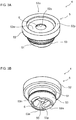
Fig. 3A is a perspective view of thevalve member 4 inFig. 2 taken from above andFig. 3B is a perspective view of thevalve member 4 taken from below. -
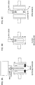
Fig. 4A is a plan view of thevalve member 4 inFig. 2 andFig. 4B is a bottom view of thevalve member 4. -
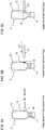
Fig. 5A is an A-A cross-sectional view ofFig. 4A andFig. 5B is a B-B cross-sectional view ofFig. 4A . -
Fig. 6A is a cross-sectional view taken along line C-C ofFigs. 5A and 5B ,Fig. 6B is a cross-sectional view taken along line D-D ofFigs. 5A and 5B , andFig. 6C is a cross-sectional view taken along line E-E ofFigs. 5A and 5B . -
Fig. 7A is a cross-sectional view illustrating a state where thevalve member 4 is mounted to anouter shell 12 andFig. 7B is a cross-sectional view illustrating a state where amobile part 6 abuts on astopper 52s to close acavity 50. -
Figs. 8A-8C are diagrams illustrating a procedure of manufacturing thedelaminatable container 1 inFig. 1 . -
Figs. 9A-9C are diagrams illustrating the procedure of manufacturing thedelaminatable container 1 inFig. 1 followingFig. 8C . -
Figs. 10A-10E are diagrams illustrating the procedure of manufacturing thedelaminatable container 1 inFig. 1 followingFig. 9C . -
Fig. 11A is a side view of atest probe 83 used in a procedure of air leakage inspection andFig. 11B is a front view of thetest probe 83. -
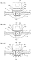
Figs. 12A-12C are diagrams illustrating the procedure of air leakage inspection. -
Fig. 13A is a schematic diagram illustrating anupper surface 52u of atube 5 of thevalve member 4 of thedelaminatable container 1 inFig. 1 andFigs. 13B-13D are schematic diagrams illustrating respectiveupper surfaces 52u of thetubes 5 of thevalve members 4 according to modifications of the present invention. - Embodiments of the present invention are described below. Various characteristics in the embodiments described below may be combined with each other. Each characteristic is independently inventive.
- As illustrated in
Fig. 1 , adelaminatable container 1 in an embodiment of the present invention is provided with acap 2 and acontainer body 3. Thecontainer body 3 is provided with avalve member 4, astorage portion 7 to store contents, and amouth 9 to discharge the contents from thestorage portion 7. In the present embodiment, thecap 2 is threaded while it may be mounted by press fitting. - As illustrated in
Fig. 2 , thecontainer body 3 is provided with anouter layer 11 and aninner layer 13 in thestorage portion 7 and themouth 9. Anouter shell 12 is composed of theouter layer 11 and aninner bag 14 is composed of theinner layer 13. Due to delamination of theinner layer 13 from theouter layer 11 with a decrease in the contents, theinner bag 14 separates from theouter shell 12 to be shrunk. Thecontainer body 3 has a layer structure where theouter layer 11 is formed thicker than theinner layer 13 so as to increase the restorability thereof. Theouter layer 11 is formed of, for example, low-density polyethylene, linear low-density polyethylene, high-density polyethylene, polypropylene, an ethylene-propylene copolymer, or a mixture thereof, or the like. Theouter layer 11 may have a multilayer structure. Theinner layer 13 is preferably composed of a plurality of layers. For example, an EVOH layer containing an ethylene-vinyl alcohol copolymer (EVOH) resin may be used as a layer to be in contact with theouter layer 11. For example, an inner surface layer containing polyolefin, such as low-density polyethylene, linear low-density polyethylene, high-density polyethylene, polypropylene, an ethylene-propylene copolymer, and a mixture thereof, may be used as a layer to be in contact with the contents. An adhesive layer is preferably used between the EVOH layer and the inner surface layer. - As illustrated in
Fig. 2 , thevalve member 4 is inserted into afresh air inlet 15 formed in thestorage portion 7 to regulate entrance and exit of air between an external space S and anintermediate space 21 between theouter shell 12 and theinner bag 14. Thefresh air inlet 15 is a through hole provided only in theouter shell 12 and does not reach theinner bag 14. As illustrated inFigs. 2 ,3A, and 3B , thevalve member 4 is provided with atube 5 having acavity 50 provided to communicate theintermediate space 21 with the external space S and an approximately sphericalmobile part 6 movably stored in thecavity 50. Thetube 5 and themobile part 6 are formed by injection molding or the like. - As illustrated in
Figs. 3A-5B , thetube 5 has astem 51 with a narrow diameter arranged in thefresh air inlet 15, a disc-shaped stoppingportion 52 provided on the external space S side of thestem 51 and preventing entrance of thetube 5 into theintermediate space 21, and a diametrically expandedportion 53 provided on theintermediate space 21 side of thestem 51 and preventing thetube 5 from outside thecontainer body 3. The stoppingportion 52 has anupper surface 52u (i.e., an outer surface on the external space S side of the tube 5) with an opening 52o formed to be connected with thecavity 50, and in the surroundings of the opening 52o, anadjacent region 52a is formed. Theadjacent region 52a is a flat circular region to be a region to locate a protrudingportion 83p of atest probe 83 during leakage inspection described later. In the exterior of theadjacent region 52a on theupper surface 52u of the stoppingportion 52, an annularprotruding region 52p is formed that protrudes from theadjacent region 52a to the external space S side. In this situation, the relationship between theadjacent region 52a and theprotruding region 52p may be considered that theadjacent region 52a is a more recessed region than theprotruding region 52p with reference to theprotruding region 52p. - The
cavity 50 is a hole axially (in a direction vertical to the fresh air inlet 15) penetrating thetube 5, and to store the sphericalmobile part 6, has theintermediate space 21 side and the external space S side in the axial direction in a narrower shape than the center. Specifically, as illustrated inFigs. 5A and 5B , theintermediate space 21 side of thecavity 50 has an area corresponding to the inside of the stoppingportion 52. This area has a truncated cone shape with a smaller diameter towards the external space S side and is provided with astopper 52s formed across the circumference to stop themobile part 6 and to block air communication. Meanwhile, theintermediate space 21 side of thecavity 50 has two facing areas provided with a pair of holdingportions 53p inwardly protruding in the radial direction to hold themobile part 6 stored in the cavity 50 (refer toFigs. 3B and5A ). In the present embodiment, the holdingportions 53p have inclined surfaces 53p1 inclined towards the external space S side on which themobile part 6 abuts to hold themobile part 6. - As illustrated in
Figs. 6A-6C , thecavity 50 thus configured has a transverse cross-sectional shape where the cross section in a position corresponding to the stopping portion 52 (C-C cross section) has a circular shape with a gradually smaller diameter towards the external space S side. The cross section in a position corresponding to the stem 51 (D-D cross section) has a shape containing a pair ofparallel plane walls 51s and twoarcuate walls 51c that are formed by notching the circle in two facing areas. The cross section in a position corresponding to the diametrically expanded portion 53 (E-E cross section) has a shape containing a pair ofparallel plane walls 53s and twoarcuate walls 53c that are formed by notching the circle in two facing areas. In this situation, theplane walls 53s are formed by the inclined surfaces 53p1. - The holding
portions 53p having the inclined surfaces 53p1 that are inclined towards the external space S side inhibit peeling of the holdingportions 53p to be undercuts when a core pin to mold thecavity 50 of thetube 5 is withdrawn from theintermediate space 21 side in formation of thetube 5 by injection molding. As illustrated inFig. 5A , the holdingportions 53p also have inclined surfaces 53p2, inclined towards theintermediate space 21 side, on theintermediate space 21 side. - As illustrated in
Figs. 3B and4B , thetube 5 has a tip end portion (an end of the diametrically expanded portion 53) provided with an annularflat surface 53e and two circumferentially facing areas provided withnotches 53n formed by notching theflat surface 53e. - As illustrated in
Fig. 7A , themobile part 6 is introduced into thecavity 50 of thetube 5 having the shape as above from theintermediate space 21 side (diametrically expandedportion 53 side). In this situation, thetube 5 is provided with the holdingportions 53p while the holdingportions 53p have the inclined surfaces 53p2, and thus themobile part 6 is allowed to be inserted into thecavity 50 over the holdingportions 53p. - With the
mobile part 6 stored in thecavity 50 of thetube 5, on the cross section in a position corresponding to the stem 51 (D-D cross section) as illustrated inFig. 6B , a distance d1 between the pair ofplane walls 51s is slightly greater than a diameter d2 of themobile part 6. A value (d1/d2) of the ratio of the distance d1 between the pair ofplane walls 51s to the diameter d2 of themobile part 6 is preferably from 1.01 to 1.20. Specifically, this ratio is, for example, 1.01, 1.02, 1.03, 1.04, 1.05, 1.06, 1.07, 1.08, 1.09, 1.10, 1.11, 1.12, 1.13, 1.14, 1.15, 1.16, 1.17, 1.18, 1.19, and 1.20 or it may be in a range between any two values exemplified here. In the embodiment illustrated inFig. 6B , d1/d2 = 1.09 (d1 = 2.60 mm, d2 = 2.38 mm). A value (d3/d2) of the ratio of a diameter d3 of thearcuate walls 51c to the diameter d2 of themobile part 6 is preferably from 1.02 to 1.60. Specifically, this ratio is, for example, 1.02, 1.04, 1.06, 1.08, 1.10, 1.12, 1.14, 1.16, 1.18, 1.20, 1.22, 1.24, 1.26, 1.28, 1.30, 1.32, 1.34, 1.36, 1.38, 1.40, 1.42, 1.44, 1.46, 1.48, 1.50, 1.52, 1.54, 1.56, 1.58, and 1.60 or it may be in a range between any two values exemplified here. In the embodiment illustrated inFig. 6B , d3/d2 = 1.26 (d3 = 3.00 mm, d2 = 2.38 mm). The diameter d3 is preferably greater than the distance d1. Such dimensional relationship allows themobile part 6 to move vertically (direction vertical to the axis) in thecavity 50 and also allows an air communication path to be secured in agap 50g between thearcuate walls 51c and themobile part 6. Meanwhile, on the cross section in a position corresponding to the diametrically expanded portion 53 (E-E cross section) as illustrated inFig. 6C , a distance d4 between theplane walls 53s is smaller than the diameter d2 of themobile part 6 to allow themobile part 6 to be held. It should be noted that, in the E-E cross section as well, thegap 50g is formed between thearcuate walls 53c and themobile part 6 to let themobile part 6 pass through thegap 50g and not to interfere with air flow even when themobile part 6 is held by the holdingportions 53p. - As illustrated in
Fig. 7A , thevalve member 4 configured as above is mounted to thecontainer body 3 by inserting the diametrically expandedportion 53 into theintermediate space 21 while pressing and expanding thefresh air inlet 15 by the diametrically expandedportion 53. When the stoppingportion 52 is pressed into the position abutting on an outer surface of theouter shell 12, thevalve member 4 is held by theouter shell 12 in the state where an outer circumferential surface of thestem 51 closely contacts with an edge of thefresh air inlet 15. The close contact of the outer circumferential surface of thestem 51 with the edge of thefresh air inlet 15 inhibits leakage of the air in theintermediate space 21 from a clearance between the edge of thefresh air inlet 15 and thetube 5 when thecontainer body 3 is compressed. - The
tube 5 is mounted to thecontainer body 3 by close contact of the outer circumferential surface of thestem 51 with the edge of thefresh air inlet 15, and the diametrically expandedportion 53 is thus not essential. Since thetube 5 has a tip end provided with theflat surface 53e, theinner bag 14 is not easily damaged even when thevalve member 4 is pressed into theintermediate space 21 and the tip end of thevalve member 4 collides with theinner bag 14. In addition, in the present embodiment, thestopper 52s is formed inside the stoppingportion 52, shifted from thestem 51 to the external space S side, and thestopper 52s is thus not deformed even when thestem 51 is pressed by the edge of thefresh air inlet 15 to allow air communication to be blocked appropriately. - When the
outer shell 12 is compressed while air is in theintermediate space 21, the air in theintermediate space 21 enters into thecavity 50 from the diametrically expandedportion 53 side, and as illustrated in Fig.an
air circulation groove 7b , causes themobile part 6 to be lifted and abut on thestopper 52s. When themobile part 6 is stopped by thestopper 52s, the air flow through thecavity 50 is blocked. When theouter shell 12 is further compressed in this state, the pressure in theintermediate space 21 is increased, and as a result, theinner bag 14 is compressed to discharge the contents in theinner bag 14. - When the compressive force to the
outer shell 12 is released, theouter shell 12 attempts to restore its shape by the elasticity of its own. The pressure in theintermediate space 21 is reduced with the restoration of theouter shell 12, and as illustrated inFig. 7B , a force F in a direction inside the container is applied to themobile part 6. This causes themobile part 6 to move towards the bottom of thecavity 50 to the state illustrated inFig. 7A , and fresh air is thus introduced into theintermediate space 21 through the clearance between themobile part 6 and the walls constituting thecavity 50. In the present embodiment, since thegap 50g is formed betweenmobile part 6 and thearcuate walls Figs. 6B and 6C ), the cross-sectional area to take in fresh air increases particularly after discharge of the contents and the restorability of theouter shell 12 is improved. - The
storage portion 7 is covered with a shrink film after thevalve member 4 is mounted. At this point, to avoid interference with the shrink film by thevalve member 4, thevalve member 4 is mounted to a valvemember mounting recess 7a provided in thestorage portion 7. In addition, not to tightly close the valvemember mounting recess 7a with the shrink film, anair circulation groove 7b is provided that extends in the direction from the valvemember mounting recess 7a to the mouth 9 (refer toFig. 1 ). Since thevalve member 4 in the present embodiment is provided with the annularprotruding region 52p, protruding from theadjacent region 52a to the external space S side, in the exterior of theadjacent region 52a on theupper surface 52u of thetube 5, the shrink film abuts on theprotruding region 52p to prevent the shrink film to be in contact with themobile part 6 and to interfere with the motion of themobile part 6. - As illustrated in
Fig. 7B , thevalve member 4 in the present embodiment is configured, with themobile part 6 stopped by thestopper 52s, to locate a height position h1 (in this context, with reference to the outer surface of theouter shell 12 while thetube 5 is mounted to theouter shell 12, same below), in a direction vertical to thefresh air inlet 15, of the end on the external space side of themobile part 6 higher than a height position h2 of the adjacent region52a of the tube 5 (h1>h2). That is to say, while themobile part 6 is stopped by thestopper 52s, themobile part 6 is configured to be partially out of the opening 62o. Such a configuration achieves a greater amount of movement of themobile part 6 even when thecavity 50 is small and allows miniaturization (reduction in thickness) of thevalve member 4. In addition, with themobile part 6 stopped by thestopper 52s, the height position h1, in the direction vertical to thefresh air inlet 15, of the end on the external space side of themobile part 6 is configured to be lower than a height position h3 of theprotruding region 52p (h1<h3). Such a configuration allows effective inhibition of contact of themobile part 6 with the shrink film. - With reference to
Figs. 8A-12C , a description is then given to an example of a method of manufacturing thedelaminatable container 1 in the present embodiment. - First, as illustrated in
Fig. 8A , a laminated parison in a molten state having a laminated structure (as an example, in order from the container inner surface side, a laminated structure of PE layer / adhesion layer / EVOH layer / PP layer / repro layer / PP layer) corresponding to thecontainer body 3 to be manufactured is extruded and the laminated parison in a molten state is set in split molds by blocking air communication for blow molding and the split molds are closed. - Then, as illustrated in
Fig. 8B , a blow nozzle is inserted into an opening portion on themouth 9 side of thecontainer body 3 to blow air into the cavity of the split molds in the state of mold closure. - Then, as illustrated in
Fig. 8C , the split molds are opened to take out the blow molded article. The split molds have a cavity shape to form the various shapes of thecontainer body 3, such as the valvemember mounting recess 7a and theair circulation groove 7b, in a blow molded article. The split molds are provided with a pinch-off in a position corresponding to the bottom of thecontainer body 3, and lower burrs are formed in this area and they are removed. In the above procedure, thecontainer body 3 having theouter shell 12 and theinner bag 14 is formed (container body formation procedure). - Then, using an arbitrary perforator, the
fresh air inlet 15 is formed in theouter shell 12 of the container body 3 (fresh air inlet formation procedure). A detailed description on this procedure is omitted. - Then, as illustrated in
Fig. 9A , ablower 80 is used to blow air between theouter shell 12 and theinner bag 14 through thefresh air inlet 15 for preliminary delamination of theinner bag 14 from the outer shell 12 (preliminary delamination procedure). In this procedure, by blowing air in a defined amount while avoiding air leakage through thefresh air inlet 15, preliminary delamination of theinner bag 14 is readily controlled. The preliminary delamination may be performed in theentire storage portion 7 or only in a partial region of thestorage portion 7. Since it is not possible to check the presence of pinholes in the inner bag 14 (air leakage inspection) in the area not subjected to the preliminary delamination, theinner bag 14 is preferably preliminary delaminated from theouter shell 12 in the approximatelyentire storage portion 7. - After the preliminary delamination procedure, as illustrated in
Figs. 9B-9C , aninsertion tool 81 is moved as illustrated in an arrow XI direction to insert the insertion tool 42 from thefresh air inlet 15. Theinner bag 14 is then pressed inside thecontainer body 3 by theinsertion tool 81 to separate theinner bag 14 from the outer shell 12 (inner bag separation procedure). This method allows large local separation of theinner bag 14 from theouter shell 12. - Then, as illustrated in
Figs. 10A-10B , arobot arm 82 is moved in the arrow X1 direction while adsorbing thevalve member 4 and presses thevalve member 4 into thefresh air inlet 15 to mount thevalve member 4 to the outer shell 12 (valve member mounting procedure). Since the diametrically expandedportion 53 has a diameter larger than that of thefresh air inlet 15, the diametrically expandedportion 53 passes through thefresh air inlet 15 while pressing and expanding thefresh air inlet 15. Then, immediately after the diametrically expandedportion 53 passes through thefresh air inlet 15, the diametrically expandedportion 53 forcibly moves towards the inside of thecontainer body 3. At this point, if the diametrically expandedportion 53 collides with theinner bag 14, theinner bag 14 has a risk of being damaged. In the present embodiment, theinner bag 14 is separated from theouter shell 12 in advance in the inner bag separation procedure, and the diametrically expandedportion 53 scarcely or not at all makes contact with theinner bag 14 and theinner bag 14 is not damaged. - Then, as illustrated in
Figs. 10C-10D , an airleakage test probe 83 is used to check whether there is a pinhole in theinner bag 14 for air leakage inspection (air leakage inspection procedure). The air leakage inspection procedure is described below in detail. - As illustrated in
Fig. 11A , thetest probe 83 used in the air leakage inspection procedure is provided with aflowmeter 83f therein. As illustrated inFig. 11B , thetest probe 83 has atip end surface 83e provided with a protrudingportion 83p formed in an approximately cross shape in a front view andcommunication holes 83h to introduce air into thetest probe 83 formed in four areas displaced from the protrudingportion 83p. - In the air leakage inspection procedure, first, as illustrated in
Figs. 12A-12B , thetip end surface 83e of thetest probe 83 is abut on theupper surface 52u of thetube 5 of thevalve member 4. In the present embodiment, in this situation, thetip end surface 83e of thetest probe 83 abuts on theprotruding region 52p of thetube 5 across the entire circumference of theprotruding region 52p. When thetip end surface 83e of thetest probe 83 abuts on theprotruding region 52p of thetube 5, the protrudingportion 83p of thetest probe 83 is positioned immediately above the opening 52o (refer toFig. 12B ). - Then, as illustrated in
Fig. 10D , air is blown from themouth 9 into the container (into the inner bag 14) while thetip end surface 83e of thetest probe 83 abuts on theprotruding region 52p of thetube 5. Then, the internal pressure in theinner bag 14 increases, and as illustrated inFig. 12C , theinner bag 14 and theouter shell 12 near thefresh air inlet 15 once separated due to the inner bag preliminary delamination procedure and the inner bag separation procedure are closely contact with each other again and theinner bag 14 also closely contacts with the mountedvalve member 4. Since the diametrically expandedportion 53 has the end providing theflat surface 53e, theinner bag 14 is not damaged even when theinner bag 14 closely contacts with the mountedvalve member 4. In addition, since theflat surface 53e is provided with the notches, even the case of close contact of thevalve member 4 with theinner bag 14 does not interfere with the air flow. In this situation, if there is a pinhole in theinner bag 14, the air blown into theinner bag 14 leaks into theintermediate space 21 and the internal pressure in theintermediate space 21 also rises, causing the air flowing through thetube 5 of thevalve member 4 into thecommunication holes 83h of thetest probe 83. In this situation, since thetip end surface 83e of thetest probe 83 abuts on theprotruding region 52p of thetube 5 across the entire circumference of theprotruding region 52p, the air does not leak into the external space S. Then, the incoming flow of the air is detected by theflowmeter 83f in thetest probe 83 to allow detection of air leakage, that is, a pinhole. - If there is a pinhole in the
inner bag 14 in the air leakage inspection procedure, the internal pressure in theintermediate space 21 may cause themobile part 6 of thevalve member 4 to be lifted and themobile part 6 may be stopped by thestopper 52s to block the air flow (refer to themobile part 6 drawn with a broken line inFig. 12C ). However, in the present embodiment as illustrated inFig. 7B , with themobile part 6 stopped by thestopper 52s, the height position h1, in the direction vertical to thefresh air inlet 15, of the end on the external space side of themobile part 6 is configured to be located higher than the height position h2 of theadjacent region 52a of thetube 5, and the protrudingportion 83p of thetest probe 83 is positioned immediately above the opening 52o of thetube 5. Themobile part 6 in thecavity 50 is thus not capable of moving to the external space S until abutting on thestopper 52s, and the air communication is not blocked as long as thetest probe 83 abuts on thevalve member 4. That is to say, the protrudingportion 83p of thetest probe 83 in the present embodiment functions as a movement restriction mechanism to restrict the movement of themobile part 6 to the external space S side. In addition, the cross shaped protrudingportion 83p allow restrict of the movement of themobile part 6 even if a minor error occurs in the position on which thetest probe 83 abuts. - Then, as illustrated in
Fig. 10E , an upper tubular portion 9a is cut, and after that, theinner bag 14 is filled with the contents, thecap 2 is mounted to themouth 9 of thecontainer body 3 and thestorage portion 7 is covered with the shrink film to finish the product. - The order of various procedures described here may be switched appropriately. For example, the procedure of cutting the upper tubular portion 9a may be performed before inserting the
valve member 4 into thefresh air inlet 15. Some of the procedures, such as the preliminary delamination procedure and the inner bag separation procedure, may be omitted. - The present invention may be carried out in the following embodiments.
- Although the
upper surface 52u of thetube 5 in the above embodiment has the protrudingregion 52p is annularly provided across the entire circumference of theadjacent region 52a as illustrated inFig. 13A , the shape of theprotruding region 52p is not limited to this embodiment. For example, the protrudingregion 52p may be provided in two facing areas across the opening 52o as illustrated inFig. 13B , many projections may be formed in the periphery of theadjacent region 52a to use them as theprotruding region 52p as illustrated inFig. 13C , or some regions circumferentially outside the opening 52o may be defined as theadjacent region 52a and the rest as theprotruding region 52p. The shape of the protrudingportion 83p of thetest probe 83 used for the air leakage inspection procedure is preferably changed in accordance with the shape of theprotruding region 52p (e.g., forFig. 13D , the protrudingportion 83p of thetest probe 83 is preferably in an I shape, not the cross shape). - Although the height position h1, in the direction vertical to the
fresh air inlet 15, of the end on the external space side of themobile part 6 is configured to be higher than the height position h2 of theadjacent region 52a of the tube 5 (h1>h2) in the state where themobile part 6 is stopped by thestopper 52s as illustrated inFig. 7B , themobile part 6 may be configured not to protrude from theadjacent region 52a. In this case, the protrudingportion 83p of thetest probe 83 used for the air leakage inspection procedure preferably has a smaller diameter than the diameter of the opening 52o of thetube 5. - Although the
mobile part 6 in the above embodiment is configured to be introduced into thecavity 50 from theintermediate space 21 side, the mobile part may be configured to be introduced from the external space S side. - 1: Delaminatable Container, 2: Cap, 3: Container Body, 4: Valve Member, 5: Tube, 6: Mobile Part, 7: Storage Portion, 7a: Valve Member Mounting Recess, 7b: Air Circulation Groove, 9: Mouth, 9a: Upper Tubular Portion, 11: Outer Layer, 12: Outer Shell, 13: Inner Layer, 14: Inner Bag, 15: Fresh Air Inlet, 21: Intermediate Space, 50: Cavity, 50g: Gap, 51: Stem, 51c: Arcuate Wall, 51s: Plane Wall, 52: Stopping Portion, 52a: Adjacent Region, 52o: Opening, 52p: Protruding Region, 52s: Stopper, 52u: Upper Surface, 53: Diametrically Expanded Portion, 53c: Arcuate Wall, 53e: Flat Surface, 53n: Notch, 53p: Holding Portion, 53p1: Inclined Surface, 53p2: Inclined Surface, 53s: Plane Wall, 80: Blower, 81: Insertion Tool, 82: Robot Arm, 83: Air Leakage Test Probe, 83e: Tip End Surface, 83f: Flowmeter, 83h: Communication Hole, 83p: Protruding Portion, S: External Space, d1, d4: Distance , d2, d3: Diameter, h1-h3: Height Position
Claims (2)
- A delaminatable container comprising an outer shell and an inner bag, the inner bag to be shrunk with a decrease in contents, wherein
the outer shell includes a fresh air inlet communicating an external space with an intermediate space between the outer shell and the inner bag,
the fresh air inlet has a valve member mounted thereto to regulate air communication between the intermediate space and the external space,
the valve member includes a tube having a cavity provided to communicate the external space with the intermediate space and a mobile part movably stored in the cavity,
the tube has a stopper to stop the mobile part in movement of the mobile part from a side of the intermediate space towards a side of the external space and to block air communication through the cavity,
the tube has an outer surface on the external space side provided with an adjacent region formed adjacent to an opening on the external space side of the cavity and a protruding region protruding from the adjacent region, and
the valve member is configured, with the mobile part stopped by the stopper, to locate a height position, in a direction vertical to the fresh air inlet, of an end on the external space side of the mobile part higher than a height of the adjacent region. - An air leakage inspection method for a delaminatable container, the container having an outer shell and an inner bag, the inner bag to be shrunk with a decrease in contents,
the delaminatable container including a fresh air inlet provided in the outer shell and communicating an external space with an intermediate space between the outer shell and the inner bag and a valve member to regulate air communication mounted to the fresh air inlet,
the valve member including a tube having a cavity provided to communicate one side with another side and a mobile part movably stored in the cavity,
the tube including a stopper to stop the mobile part in movement of the mobile part from a side of the intermediate space towards a side of the external space and to block air communication through the cavity,
the tube having a surface on said another side provided with an adjacent region formed adjacent to an opening on said another side of the cavity and a protruding region formed in an exterior of the adjacent region relative to the opening, and
the delaminatable container being configured, with the mobile part stopped by the stopper, to locate a height position, in a direction vertical to the fresh air inlet, of an end on the external space side of the mobile part higher than a height of the adjacent region and lower than the protruding region,
the method comprising air leakage inspecting that measures a flow rate of air leaked from the fresh air inlet by a test probe provided with a flowmeter, wherein
the air leakage inspecting is performed by positioning a movement restriction mechanism provided on the test probe in the adjacent region while restricting movement of the mobile part to the external space side.
Applications Claiming Priority (2)
| Application Number | Priority Date | Filing Date | Title |
|---|---|---|---|
| JP2017158874A JP7004898B2 (en) | 2017-08-21 | 2017-08-21 | Air leak inspection method for laminated peeling container and laminated peeling container |
| PCT/JP2018/030404 WO2019039374A1 (en) | 2017-08-21 | 2018-08-16 | Multilayer container and method for inspecting air leaks in multilayer container |
Publications (3)
| Publication Number | Publication Date |
|---|---|
| EP3674224A1 true EP3674224A1 (en) | 2020-07-01 |
| EP3674224A4 EP3674224A4 (en) | 2020-09-23 |
| EP3674224B1 EP3674224B1 (en) | 2022-04-13 |
Family
ID=65438887
Family Applications (1)
| Application Number | Title | Priority Date | Filing Date |
|---|---|---|---|
| EP18847821.8A Active EP3674224B1 (en) | 2017-08-21 | 2018-08-16 | Multilayer container and method for inspecting air leaks in multilayer container |
Country Status (7)
| Country | Link |
|---|---|
| US (1) | US11643262B2 (en) |
| EP (1) | EP3674224B1 (en) |
| JP (1) | JP7004898B2 (en) |
| KR (1) | KR102602913B1 (en) |
| CN (1) | CN110831864B (en) |
| TW (1) | TWI768101B (en) |
| WO (1) | WO2019039374A1 (en) |
Families Citing this family (4)
| Publication number | Priority date | Publication date | Assignee | Title |
|---|---|---|---|---|
| ES2762865T3 (en) * | 2016-09-26 | 2020-05-26 | Boehringer Ingelheim Int | Procedure to test the tightness of a bag in the interior of a container |
| CN110382371A (en) * | 2017-03-15 | 2019-10-25 | 京洛株式会社 | Laminated peeling container |
| CN112499010B (en) * | 2020-12-02 | 2024-08-06 | 上海元捷供应链管理有限公司 | Storage device for dangerous chemicals |
| JP7653023B2 (en) * | 2021-08-20 | 2025-03-28 | キョーラク株式会社 | Double container manufacturing method |
Family Cites Families (14)
| Publication number | Priority date | Publication date | Assignee | Title |
|---|---|---|---|---|
| JP2001026958A (en) | 1999-07-14 | 2001-01-30 | Yoshiya Kozono | Ventilation device for drain pipe |
| US6644510B2 (en) * | 2001-06-29 | 2003-11-11 | The Meyer Company | Bag-in-box container and faucet |
| DE102004056270A1 (en) * | 2004-11-22 | 2006-05-24 | Basf Ag | Side guide for the curtain coating |
| FR2889836A3 (en) * | 2005-08-18 | 2007-02-23 | Raymond Castanet | METHOD AND DEVICE FOR STORING AND DISPENSING A FLUID OR PASTY PRODUCT |
| EP3075672B1 (en) * | 2013-11-27 | 2018-04-04 | Kyoraku Co., Ltd. | Delamination container |
| CN105793162B (en) * | 2013-11-27 | 2019-07-02 | 京洛株式会社 | Laminated peel container and method for producing the same |
| ES2737105T3 (en) * | 2013-11-27 | 2020-01-10 | Kyoraku Co Ltd | Delaminable container |
| AU2015329264B2 (en) | 2014-10-07 | 2018-08-30 | Kyoraku Co., Ltd. | Delaminated container manufacturing method and air leak inspection method for delaminated container |
| JP6761159B2 (en) | 2014-11-19 | 2020-09-23 | キョーラク株式会社 | Laminate peeling container |
| US10723500B2 (en) | 2014-12-09 | 2020-07-28 | Kyoraku Co., Ltd. | Delamination container, method for attaching cap to delamination container, and method for manufacturing delamination container |
| CA2916290A1 (en) * | 2014-12-30 | 2016-06-30 | Dennis M. Yager | Forage gas relief valve device |
| WO2016121578A1 (en) * | 2015-01-27 | 2016-08-04 | キョーラク株式会社 | Layer separating container |
| WO2017073721A1 (en) * | 2015-10-30 | 2017-05-04 | キョーラク株式会社 | Delamination container |
| US10822135B2 (en) | 2015-12-03 | 2020-11-03 | Kyoraku Co., Ltd. | Delaminatable container |
-
2017
- 2017-08-21 JP JP2017158874A patent/JP7004898B2/en active Active
-
2018
- 2018-08-16 KR KR1020197038813A patent/KR102602913B1/en active Active
- 2018-08-16 TW TW107128566A patent/TWI768101B/en active
- 2018-08-16 CN CN201880044314.8A patent/CN110831864B/en active Active
- 2018-08-16 WO PCT/JP2018/030404 patent/WO2019039374A1/en not_active Ceased
- 2018-08-16 US US16/636,379 patent/US11643262B2/en active Active
- 2018-08-16 EP EP18847821.8A patent/EP3674224B1/en active Active
Also Published As
| Publication number | Publication date |
|---|---|
| CN110831864A (en) | 2020-02-21 |
| KR102602913B1 (en) | 2023-11-15 |
| WO2019039374A1 (en) | 2019-02-28 |
| EP3674224A4 (en) | 2020-09-23 |
| TW201930153A (en) | 2019-08-01 |
| US20200172312A1 (en) | 2020-06-04 |
| JP7004898B2 (en) | 2022-02-10 |
| EP3674224B1 (en) | 2022-04-13 |
| TWI768101B (en) | 2022-06-21 |
| US11643262B2 (en) | 2023-05-09 |
| JP2019034784A (en) | 2019-03-07 |
| CN110831864B (en) | 2022-04-12 |
| KR20200043314A (en) | 2020-04-27 |
Similar Documents
| Publication | Publication Date | Title |
|---|---|---|
| EP3674224B1 (en) | Multilayer container and method for inspecting air leaks in multilayer container | |
| JP7108206B2 (en) | delaminating container | |
| EP3385181B1 (en) | Lamination separable container | |
| KR102093254B1 (en) | Delamination container | |
| US9546028B2 (en) | Mouthpiece structure for pressure vessel | |
| US20190100344A1 (en) | Delaminatable container | |
| JP7051015B2 (en) | Fuel tank | |
| US11701964B2 (en) | Fuel tank | |
| JP2016043489A (en) | Method for manufacturing double-walled container | |
| JP7025637B2 (en) | Laminated peeling container | |
| JP2018012511A (en) | Delamination container | |
| WO2019131416A1 (en) | Lamination-separable container | |
| JP7314537B2 (en) | cap for multiple containers | |
| WO2017142027A1 (en) | Double-layered container and method for production of same | |
| US12172514B2 (en) | Fuel tank | |
| JP7385102B2 (en) | Storage container and its manufacturing method | |
| JP2018090287A (en) | Coating tool | |
| CN112041234B (en) | Container | |
| JP7235947B2 (en) | delaminating container | |
| CN116280581A (en) | container | |
| WO2020158549A1 (en) | Accommodation container and method for manufacturing same | |
| WO2016080313A1 (en) | Lamination separation container |
Legal Events
| Date | Code | Title | Description |
|---|---|---|---|
| STAA | Information on the status of an ep patent application or granted ep patent |
Free format text: STATUS: THE INTERNATIONAL PUBLICATION HAS BEEN MADE |
|
| PUAI | Public reference made under article 153(3) epc to a published international application that has entered the european phase |
Free format text: ORIGINAL CODE: 0009012 |
|
| STAA | Information on the status of an ep patent application or granted ep patent |
Free format text: STATUS: REQUEST FOR EXAMINATION WAS MADE |
|
| 17P | Request for examination filed |
Effective date: 20200317 |
|
| AK | Designated contracting states |
Kind code of ref document: A1 Designated state(s): AL AT BE BG CH CY CZ DE DK EE ES FI FR GB GR HR HU IE IS IT LI LT LU LV MC MK MT NL NO PL PT RO RS SE SI SK SM TR |
|
| AX | Request for extension of the european patent |
Extension state: BA ME |
|
| A4 | Supplementary search report drawn up and despatched |
Effective date: 20200825 |
|
| RIC1 | Information provided on ipc code assigned before grant |
Ipc: B65D 83/00 20060101ALI20200819BHEP Ipc: B65D 1/02 20060101AFI20200819BHEP |
|
| DAV | Request for validation of the european patent (deleted) | ||
| DAX | Request for extension of the european patent (deleted) | ||
| STAA | Information on the status of an ep patent application or granted ep patent |
Free format text: STATUS: EXAMINATION IS IN PROGRESS |
|
| 17Q | First examination report despatched |
Effective date: 20210219 |
|
| GRAJ | Information related to disapproval of communication of intention to grant by the applicant or resumption of examination proceedings by the epo deleted |
Free format text: ORIGINAL CODE: EPIDOSDIGR1 |
|
| GRAP | Despatch of communication of intention to grant a patent |
Free format text: ORIGINAL CODE: EPIDOSNIGR1 |
|
| GRAP | Despatch of communication of intention to grant a patent |
Free format text: ORIGINAL CODE: EPIDOSNIGR1 |
|
| STAA | Information on the status of an ep patent application or granted ep patent |
Free format text: STATUS: GRANT OF PATENT IS INTENDED |
|
| INTG | Intention to grant announced |
Effective date: 20211111 |
|
| GRAS | Grant fee paid |
Free format text: ORIGINAL CODE: EPIDOSNIGR3 |
|
| GRAA | (expected) grant |
Free format text: ORIGINAL CODE: 0009210 |
|
| STAA | Information on the status of an ep patent application or granted ep patent |
Free format text: STATUS: THE PATENT HAS BEEN GRANTED |
|
| AK | Designated contracting states |
Kind code of ref document: B1 Designated state(s): AL AT BE BG CH CY CZ DE DK EE ES FI FR GB GR HR HU IE IS IT LI LT LU LV MC MK MT NL NO PL PT RO RS SE SI SK SM TR |
|
| REG | Reference to a national code |
Ref country code: GB Ref legal event code: FG4D |
|
| REG | Reference to a national code |
Ref country code: CH Ref legal event code: EP |
|
| REG | Reference to a national code |
Ref country code: DE Ref legal event code: R096 Ref document number: 602018033930 Country of ref document: DE |
|
| REG | Reference to a national code |
Ref country code: IE Ref legal event code: FG4D |
|
| REG | Reference to a national code |
Ref country code: AT Ref legal event code: REF Ref document number: 1483253 Country of ref document: AT Kind code of ref document: T Effective date: 20220515 |
|
| REG | Reference to a national code |
Ref country code: LT Ref legal event code: MG9D |
|
| REG | Reference to a national code |
Ref country code: NL Ref legal event code: MP Effective date: 20220413 |
|
| REG | Reference to a national code |
Ref country code: AT Ref legal event code: MK05 Ref document number: 1483253 Country of ref document: AT Kind code of ref document: T Effective date: 20220413 |
|
| PG25 | Lapsed in a contracting state [announced via postgrant information from national office to epo] |
Ref country code: NL Free format text: LAPSE BECAUSE OF FAILURE TO SUBMIT A TRANSLATION OF THE DESCRIPTION OR TO PAY THE FEE WITHIN THE PRESCRIBED TIME-LIMIT Effective date: 20220413 |
|
| PG25 | Lapsed in a contracting state [announced via postgrant information from national office to epo] |
Ref country code: SE Free format text: LAPSE BECAUSE OF FAILURE TO SUBMIT A TRANSLATION OF THE DESCRIPTION OR TO PAY THE FEE WITHIN THE PRESCRIBED TIME-LIMIT Effective date: 20220413 Ref country code: PT Free format text: LAPSE BECAUSE OF FAILURE TO SUBMIT A TRANSLATION OF THE DESCRIPTION OR TO PAY THE FEE WITHIN THE PRESCRIBED TIME-LIMIT Effective date: 20220816 Ref country code: NO Free format text: LAPSE BECAUSE OF FAILURE TO SUBMIT A TRANSLATION OF THE DESCRIPTION OR TO PAY THE FEE WITHIN THE PRESCRIBED TIME-LIMIT Effective date: 20220713 Ref country code: LT Free format text: LAPSE BECAUSE OF FAILURE TO SUBMIT A TRANSLATION OF THE DESCRIPTION OR TO PAY THE FEE WITHIN THE PRESCRIBED TIME-LIMIT Effective date: 20220413 Ref country code: HR Free format text: LAPSE BECAUSE OF FAILURE TO SUBMIT A TRANSLATION OF THE DESCRIPTION OR TO PAY THE FEE WITHIN THE PRESCRIBED TIME-LIMIT Effective date: 20220413 Ref country code: GR Free format text: LAPSE BECAUSE OF FAILURE TO SUBMIT A TRANSLATION OF THE DESCRIPTION OR TO PAY THE FEE WITHIN THE PRESCRIBED TIME-LIMIT Effective date: 20220714 Ref country code: FI Free format text: LAPSE BECAUSE OF FAILURE TO SUBMIT A TRANSLATION OF THE DESCRIPTION OR TO PAY THE FEE WITHIN THE PRESCRIBED TIME-LIMIT Effective date: 20220413 Ref country code: ES Free format text: LAPSE BECAUSE OF FAILURE TO SUBMIT A TRANSLATION OF THE DESCRIPTION OR TO PAY THE FEE WITHIN THE PRESCRIBED TIME-LIMIT Effective date: 20220413 Ref country code: BG Free format text: LAPSE BECAUSE OF FAILURE TO SUBMIT A TRANSLATION OF THE DESCRIPTION OR TO PAY THE FEE WITHIN THE PRESCRIBED TIME-LIMIT Effective date: 20220713 Ref country code: AT Free format text: LAPSE BECAUSE OF FAILURE TO SUBMIT A TRANSLATION OF THE DESCRIPTION OR TO PAY THE FEE WITHIN THE PRESCRIBED TIME-LIMIT Effective date: 20220413 |
|
| PG25 | Lapsed in a contracting state [announced via postgrant information from national office to epo] |
Ref country code: RS Free format text: LAPSE BECAUSE OF FAILURE TO SUBMIT A TRANSLATION OF THE DESCRIPTION OR TO PAY THE FEE WITHIN THE PRESCRIBED TIME-LIMIT Effective date: 20220413 Ref country code: PL Free format text: LAPSE BECAUSE OF FAILURE TO SUBMIT A TRANSLATION OF THE DESCRIPTION OR TO PAY THE FEE WITHIN THE PRESCRIBED TIME-LIMIT Effective date: 20220413 Ref country code: LV Free format text: LAPSE BECAUSE OF FAILURE TO SUBMIT A TRANSLATION OF THE DESCRIPTION OR TO PAY THE FEE WITHIN THE PRESCRIBED TIME-LIMIT Effective date: 20220413 Ref country code: IS Free format text: LAPSE BECAUSE OF FAILURE TO SUBMIT A TRANSLATION OF THE DESCRIPTION OR TO PAY THE FEE WITHIN THE PRESCRIBED TIME-LIMIT Effective date: 20220813 |
|
| REG | Reference to a national code |
Ref country code: DE Ref legal event code: R097 Ref document number: 602018033930 Country of ref document: DE |
|
| PG25 | Lapsed in a contracting state [announced via postgrant information from national office to epo] |
Ref country code: SM Free format text: LAPSE BECAUSE OF FAILURE TO SUBMIT A TRANSLATION OF THE DESCRIPTION OR TO PAY THE FEE WITHIN THE PRESCRIBED TIME-LIMIT Effective date: 20220413 Ref country code: SK Free format text: LAPSE BECAUSE OF FAILURE TO SUBMIT A TRANSLATION OF THE DESCRIPTION OR TO PAY THE FEE WITHIN THE PRESCRIBED TIME-LIMIT Effective date: 20220413 Ref country code: RO Free format text: LAPSE BECAUSE OF FAILURE TO SUBMIT A TRANSLATION OF THE DESCRIPTION OR TO PAY THE FEE WITHIN THE PRESCRIBED TIME-LIMIT Effective date: 20220413 Ref country code: EE Free format text: LAPSE BECAUSE OF FAILURE TO SUBMIT A TRANSLATION OF THE DESCRIPTION OR TO PAY THE FEE WITHIN THE PRESCRIBED TIME-LIMIT Effective date: 20220413 Ref country code: DK Free format text: LAPSE BECAUSE OF FAILURE TO SUBMIT A TRANSLATION OF THE DESCRIPTION OR TO PAY THE FEE WITHIN THE PRESCRIBED TIME-LIMIT Effective date: 20220413 Ref country code: CZ Free format text: LAPSE BECAUSE OF FAILURE TO SUBMIT A TRANSLATION OF THE DESCRIPTION OR TO PAY THE FEE WITHIN THE PRESCRIBED TIME-LIMIT Effective date: 20220413 |
|
| PLBE | No opposition filed within time limit |
Free format text: ORIGINAL CODE: 0009261 |
|
| STAA | Information on the status of an ep patent application or granted ep patent |
Free format text: STATUS: NO OPPOSITION FILED WITHIN TIME LIMIT |
|
| 26N | No opposition filed |
Effective date: 20230116 |
|
| PG25 | Lapsed in a contracting state [announced via postgrant information from national office to epo] |
Ref country code: MC Free format text: LAPSE BECAUSE OF FAILURE TO SUBMIT A TRANSLATION OF THE DESCRIPTION OR TO PAY THE FEE WITHIN THE PRESCRIBED TIME-LIMIT Effective date: 20220413 Ref country code: AL Free format text: LAPSE BECAUSE OF FAILURE TO SUBMIT A TRANSLATION OF THE DESCRIPTION OR TO PAY THE FEE WITHIN THE PRESCRIBED TIME-LIMIT Effective date: 20220413 |
|
| REG | Reference to a national code |
Ref country code: CH Ref legal event code: PL |
|
| PG25 | Lapsed in a contracting state [announced via postgrant information from national office to epo] |
Ref country code: LU Free format text: LAPSE BECAUSE OF NON-PAYMENT OF DUE FEES Effective date: 20220816 Ref country code: LI Free format text: LAPSE BECAUSE OF NON-PAYMENT OF DUE FEES Effective date: 20220831 Ref country code: CH Free format text: LAPSE BECAUSE OF NON-PAYMENT OF DUE FEES Effective date: 20220831 |
|
| REG | Reference to a national code |
Ref country code: BE Ref legal event code: MM Effective date: 20220831 |
|
| PG25 | Lapsed in a contracting state [announced via postgrant information from national office to epo] |
Ref country code: SI Free format text: LAPSE BECAUSE OF FAILURE TO SUBMIT A TRANSLATION OF THE DESCRIPTION OR TO PAY THE FEE WITHIN THE PRESCRIBED TIME-LIMIT Effective date: 20220413 |
|
| PG25 | Lapsed in a contracting state [announced via postgrant information from national office to epo] |
Ref country code: IE Free format text: LAPSE BECAUSE OF NON-PAYMENT OF DUE FEES Effective date: 20220816 |
|
| PG25 | Lapsed in a contracting state [announced via postgrant information from national office to epo] |
Ref country code: BE Free format text: LAPSE BECAUSE OF NON-PAYMENT OF DUE FEES Effective date: 20220831 |
|
| PGFP | Annual fee paid to national office [announced via postgrant information from national office to epo] |
Ref country code: GB Payment date: 20230822 Year of fee payment: 6 |
|
| PGFP | Annual fee paid to national office [announced via postgrant information from national office to epo] |
Ref country code: FR Payment date: 20230828 Year of fee payment: 6 |
|
| PG25 | Lapsed in a contracting state [announced via postgrant information from national office to epo] |
Ref country code: IT Free format text: LAPSE BECAUSE OF FAILURE TO SUBMIT A TRANSLATION OF THE DESCRIPTION OR TO PAY THE FEE WITHIN THE PRESCRIBED TIME-LIMIT Effective date: 20220413 |
|
| PG25 | Lapsed in a contracting state [announced via postgrant information from national office to epo] |
Ref country code: CY Free format text: LAPSE BECAUSE OF FAILURE TO SUBMIT A TRANSLATION OF THE DESCRIPTION OR TO PAY THE FEE WITHIN THE PRESCRIBED TIME-LIMIT Effective date: 20220413 |
|
| PG25 | Lapsed in a contracting state [announced via postgrant information from national office to epo] |
Ref country code: MK Free format text: LAPSE BECAUSE OF FAILURE TO SUBMIT A TRANSLATION OF THE DESCRIPTION OR TO PAY THE FEE WITHIN THE PRESCRIBED TIME-LIMIT Effective date: 20220413 Ref country code: HU Free format text: LAPSE BECAUSE OF FAILURE TO SUBMIT A TRANSLATION OF THE DESCRIPTION OR TO PAY THE FEE WITHIN THE PRESCRIBED TIME-LIMIT; INVALID AB INITIO Effective date: 20180816 |
|
| PG25 | Lapsed in a contracting state [announced via postgrant information from national office to epo] |
Ref country code: MT Free format text: LAPSE BECAUSE OF FAILURE TO SUBMIT A TRANSLATION OF THE DESCRIPTION OR TO PAY THE FEE WITHIN THE PRESCRIBED TIME-LIMIT Effective date: 20220413 |
|
| PG25 | Lapsed in a contracting state [announced via postgrant information from national office to epo] |
Ref country code: BG Free format text: LAPSE BECAUSE OF FAILURE TO SUBMIT A TRANSLATION OF THE DESCRIPTION OR TO PAY THE FEE WITHIN THE PRESCRIBED TIME-LIMIT Effective date: 20220413 |
|
| PG25 | Lapsed in a contracting state [announced via postgrant information from national office to epo] |
Ref country code: BG Free format text: LAPSE BECAUSE OF FAILURE TO SUBMIT A TRANSLATION OF THE DESCRIPTION OR TO PAY THE FEE WITHIN THE PRESCRIBED TIME-LIMIT Effective date: 20220413 |
|
| GBPC | Gb: european patent ceased through non-payment of renewal fee |
Effective date: 20240816 |
|
| PG25 | Lapsed in a contracting state [announced via postgrant information from national office to epo] |
Ref country code: GB Free format text: LAPSE BECAUSE OF NON-PAYMENT OF DUE FEES Effective date: 20240816 |
|
| PG25 | Lapsed in a contracting state [announced via postgrant information from national office to epo] |
Ref country code: FR Free format text: LAPSE BECAUSE OF NON-PAYMENT OF DUE FEES Effective date: 20240831 |
|
| PGFP | Annual fee paid to national office [announced via postgrant information from national office to epo] |
Ref country code: DE Payment date: 20250820 Year of fee payment: 8 |
|
| PG25 | Lapsed in a contracting state [announced via postgrant information from national office to epo] |
Ref country code: TR Free format text: LAPSE BECAUSE OF FAILURE TO SUBMIT A TRANSLATION OF THE DESCRIPTION OR TO PAY THE FEE WITHIN THE PRESCRIBED TIME-LIMIT Effective date: 20220413 |