EP3674203A1 - Aircraft flow body - Google Patents
Aircraft flow body Download PDFInfo
- Publication number
- EP3674203A1 EP3674203A1 EP19216410.1A EP19216410A EP3674203A1 EP 3674203 A1 EP3674203 A1 EP 3674203A1 EP 19216410 A EP19216410 A EP 19216410A EP 3674203 A1 EP3674203 A1 EP 3674203A1
- Authority
- EP
- European Patent Office
- Prior art keywords
- rib
- flow body
- outer skin
- rib portion
- aircraft
- Prior art date
- Legal status (The legal status is an assumption and is not a legal conclusion. Google has not performed a legal analysis and makes no representation as to the accuracy of the status listed.)
- Withdrawn
Links
Images
Classifications
-
- B—PERFORMING OPERATIONS; TRANSPORTING
- B64—AIRCRAFT; AVIATION; COSMONAUTICS
- B64D—EQUIPMENT FOR FITTING IN OR TO AIRCRAFT; FLIGHT SUITS; PARACHUTES; ARRANGEMENT OR MOUNTING OF POWER PLANTS OR PROPULSION TRANSMISSIONS IN AIRCRAFT
- B64D45/00—Aircraft indicators or protectors not otherwise provided for
-
- B—PERFORMING OPERATIONS; TRANSPORTING
- B64—AIRCRAFT; AVIATION; COSMONAUTICS
- B64C—AEROPLANES; HELICOPTERS
- B64C1/00—Fuselages; Constructional features common to fuselages, wings, stabilising surfaces or the like
- B64C1/06—Frames; Stringers; Longerons ; Fuselage sections
- B64C1/12—Construction or attachment of skin panels
-
- B—PERFORMING OPERATIONS; TRANSPORTING
- B64—AIRCRAFT; AVIATION; COSMONAUTICS
- B64C—AEROPLANES; HELICOPTERS
- B64C3/00—Wings
- B64C3/18—Spars; Ribs; Stringers
-
- B—PERFORMING OPERATIONS; TRANSPORTING
- B64—AIRCRAFT; AVIATION; COSMONAUTICS
- B64C—AEROPLANES; HELICOPTERS
- B64C3/00—Wings
- B64C3/18—Spars; Ribs; Stringers
- B64C3/187—Ribs
-
- B—PERFORMING OPERATIONS; TRANSPORTING
- B64—AIRCRAFT; AVIATION; COSMONAUTICS
- B64C—AEROPLANES; HELICOPTERS
- B64C3/00—Wings
- B64C3/26—Construction, shape, or attachment of separate skins, e.g. panels
-
- B—PERFORMING OPERATIONS; TRANSPORTING
- B64—AIRCRAFT; AVIATION; COSMONAUTICS
- B64C—AEROPLANES; HELICOPTERS
- B64C3/00—Wings
- B64C3/28—Leading or trailing edges attached to primary structures, e.g. forming fixed slots
-
- B—PERFORMING OPERATIONS; TRANSPORTING
- B64—AIRCRAFT; AVIATION; COSMONAUTICS
- B64C—AEROPLANES; HELICOPTERS
- B64C5/00—Stabilising surfaces
-
- B—PERFORMING OPERATIONS; TRANSPORTING
- B64—AIRCRAFT; AVIATION; COSMONAUTICS
- B64C—AEROPLANES; HELICOPTERS
- B64C9/00—Adjustable control surfaces or members, e.g. rudders
- B64C9/14—Adjustable control surfaces or members, e.g. rudders forming slots
- B64C9/22—Adjustable control surfaces or members, e.g. rudders forming slots at the front of the wing
-
- B—PERFORMING OPERATIONS; TRANSPORTING
- B29—WORKING OF PLASTICS; WORKING OF SUBSTANCES IN A PLASTIC STATE IN GENERAL
- B29L—INDEXING SCHEME ASSOCIATED WITH SUBCLASS B29C, RELATING TO PARTICULAR ARTICLES
- B29L2031/00—Other particular articles
- B29L2031/30—Vehicles, e.g. ships or aircraft, or body parts thereof
- B29L2031/3076—Aircrafts
- B29L2031/3085—Wings
-
- B—PERFORMING OPERATIONS; TRANSPORTING
- B64—AIRCRAFT; AVIATION; COSMONAUTICS
- B64C—AEROPLANES; HELICOPTERS
- B64C1/00—Fuselages; Constructional features common to fuselages, wings, stabilising surfaces or the like
- B64C2001/0054—Fuselage structures substantially made from particular materials
- B64C2001/0072—Fuselage structures substantially made from particular materials from composite materials
-
- B—PERFORMING OPERATIONS; TRANSPORTING
- B64—AIRCRAFT; AVIATION; COSMONAUTICS
- B64D—EQUIPMENT FOR FITTING IN OR TO AIRCRAFT; FLIGHT SUITS; PARACHUTES; ARRANGEMENT OR MOUNTING OF POWER PLANTS OR PROPULSION TRANSMISSIONS IN AIRCRAFT
- B64D45/00—Aircraft indicators or protectors not otherwise provided for
- B64D2045/0095—Devices specially adapted to avoid bird strike
-
- Y—GENERAL TAGGING OF NEW TECHNOLOGICAL DEVELOPMENTS; GENERAL TAGGING OF CROSS-SECTIONAL TECHNOLOGIES SPANNING OVER SEVERAL SECTIONS OF THE IPC; TECHNICAL SUBJECTS COVERED BY FORMER USPC CROSS-REFERENCE ART COLLECTIONS [XRACs] AND DIGESTS
- Y02—TECHNOLOGIES OR APPLICATIONS FOR MITIGATION OR ADAPTATION AGAINST CLIMATE CHANGE
- Y02T—CLIMATE CHANGE MITIGATION TECHNOLOGIES RELATED TO TRANSPORTATION
- Y02T50/00—Aeronautics or air transport
- Y02T50/40—Weight reduction
Definitions
- the present invention relates to an aircraft flow body and an aircraft comprising an aircraft flow body.
- the impact of one or more foreign bodies such as birds is a consideration during the design of aircraft flow bodies (wings, tails, nacelles etc.), which may be impacted by these bodies during their operational lifetime. It is a necessary consideration due to high impact energy that is imparted by the foreign object.
- the flow body structure needs to be damage tolerant and not fail to such an extent that it detaches from the aircraft. If the flow body also contains a liquid or gas tank, then the flow body should not suffer from a breach of containment.
- objects of the present invention are to provide an improved flow body design that can meet the damage tolerance and penetration criteria but also not require repair or replacement of the spar after an impact event.
- the object is solved by the features of the independent claims.
- Advantageous embodiments are subject matter of the dependent claims and the following description.
- An embodiment of the present invention provides an aircraft flow body 200 comprising a rib 201 bounded by and fixedly attached to an outer skin 203, wherein the outer skin 203 and the rib 201 are configured to plastically deform when the outer skin 203 is subjected to an impact load in a leading edge region 205 of the airflow body, wherein the stiffness of the outer skin 203 is greater than or equal to the stiffness of the rib 201 when deformed by the impact load L.
- a design of a flow body 200 where the outer skin 203 and underlying rib 201 in the leading edge region 205 are configured to deform and absorb all of the impact load/energy is advantageous in that it enables an improved distribution of deformation between the rib 201 and outer skin 203 of the flow body 200 as a result of foreign object impact and therefore substantially reduces the amount of impact energy transferred to the spar 204, which lowers the likelihood of the spar 204 undergoing plastic deformation.
- a flow body 200 design where the rib 201 has the same or lower structural stiffness during impact than the outer skin 203 to which it is attached results in a design where the rib 201 absorbs more of the impact load than the prior art. This allows the skin 203 to deform more and hence absorb more impact energy. Furthermore this reduces the likelihood of the outer skin 203 rupturing (tearing or being penetrated) before the impact load is absorbed, which may otherwise result in some foreign object debris directly impacting the spar 204 and plastically deforming it.
- the aircraft flow body 200 further comprises a comprises a first rib portion 207 of the rib 201 and a second rib portion 209 of the rib 201, wherein the first rib portion 207 is attached to the outer skin 203 in the leading edge region 205, wherein the stiffness of the outer skin 203 is greater than or equal to the stiffness of the first rib portion 201 when deformed by the impact load L and, wherein the first rib portion 207 is attached to the second rib portion 209 by a lap joint 211.
- a rib 201 with a first portion 207 configured to enable an improved distribution of impact load between the rib 201 and outer skin 203, coupled to a second rib portion 209 that may provide a separate structural function, for e.g., provide a stiffening of the spar 204) is advantageous as it results in a versatile design. Furthermore, in the event of an impact damage, the damaged first rib portion 207 may be disconnected/decoupled from an undamaged second rib portion 209, which may be attached to an undamaged spar 204. This results in a design that is less costly to repair after an impact damage as only a portion of the rib 201 may need replacement rather that the entire rib 201.
- the aircraft flow body 200 comprises a lap joint 211 that is orientated substantially perpendicular to the direction of the impact load L.
- a joint 211 between the first and second rib portions 207 209 configured as such may result impact loads being transferred more uniformly across the full height (measured in Z direction) of the rib 201, which may be advantageous in that the likelihood of plastic deformation of the second rib portion 209 and the spar 204 may be further reduced.
- the lap joint 211 comprises a single row of shear fasteners 213.
- Ajoint 211 between the first and second rib portions 207 209 provided with shear fasteners 213 configured to shear once the impact load L reaches a predetermined load may be advantageous in that as soon as the fasteners 213 fail, the reaction of the impact load will be isolated to the outer skin 203 and first rib portions 207, which may deform even further to react the impact loads.
- first rib portion 207 and second rib portion 209 are formed from dissimilar materials. Forming the rib portions 207 209 from dissimilar materials enables the rib portions to be refined for their specific structural function(s), which may reduce cost and weight of the flow body 200 as a whole.
- an aircraft 100 comprising a plurality of flow bodies such as the wing 101, horizontal tail 103, vertical tail 105, and engine nacelle 107.
- Each flow body comprises an internal structure consisting of an outer skin attached to underlying spars and/or ribs and/or stiffeners.
- the aircraft comprises a set of orthogonal aircraft axes, comprising a longitudinal X axis, a lateral (spanwise) Y axis, and a vertical Z axis.
- the region of each flow body existing in the most positive X direction is commonly referred to as the leading edge region of the flow body and is most susceptible to impact from foreign objects travelling in the -X direction.
- the wing 101 further comprises a plurality of smaller flow bodies in the form of slats 109, which are movably attached the forward (leading edge) region of the wing 101. These are constructed in substantially the same way as the larger structures in that they comprise an outer skin attached to underlying spars and/or ribs and/or stiffeners.
- a non-impacted flow body in the form of a slat 200 is shown on the left hand side.
- the slat 200 comprises an outer skin 203 that bounds, and is fixedly attached to, a rib 201 and a spar 204 that lie internally within it.
- the outer skin 203 is formed from a thin sheet alloy aluminium material (e.g. 2024 series aluminium alloy material), but any suitable metallic or composite material may alternatively be used.
- the rib 201 comprises a first rib portion 207 attached by a lap joint 211 with a single row of fasteners 213 to a second rib portion 209.
- the first rib portion 207 is attached to the outer skin 203 in the leading edge region 205 by fasteners (not shown) and is formed from a thin sheet alloy aluminium material (e.g.
- the second rib portion 209 is attached to the spar 204 aft of the leading edge region 205 by fasteners (also not shown) and is formed from a thin sheet alloy aluminium material (e.g. 2024 series aluminium alloy material), but any suitable metallic or composite material may alternatively be used.
- the second rib portion 209 comprises a connection portion 215 that attaches to a slat kinematic system for moving the slat 200 in operation.
- the rib 201 is oriented substantially vertically in a plane lying parallel to the XZ plane.
- the spar 204 is oriented substantially vertically in a plane lying parallel to the YZ plane and is constructed from a sheet aluminium alloy material (e.g. or 7010 series or 2014 series aluminium alloy), but any suitable metallic or composite material may alternatively be used.
- the outer skin 203 is subjected to aerodynamic pressure loads, which are transferred via spar 204, the rib 201 and the kinematic system to the wing 101.
- the components in the slat 200 i.e. the skin 203, rib 201 and spar 204, are also subjected to inertial loads caused by accelerations of the aircraft 101 during take-off, cruise and landing. In response to this loading the components elastically deform and deflect within predetermined limits that are pre-determined by each component's load amount, sectional properties and material mechanical properties.
- the non-impacted flow body shown on the left hand side is also shown in an impacted and plastically deformed scenario, where an impact load L acts against the leading edge region 205 of the slat 200 in a -X direction.
- the stiffness of the outer skin 203 is equal to the stiffness of the first rib portion 207 at the location where impact load L exerts itself on the structure, such that the skin 203 and first rib portion 207 deform uniformly in reaction to the impact load L, as shown.
- the impact kinetic energy is absorbed by slat 200 through deformation of the skin 203 and the first rib portion 207, and not by the second rib portion 209 and spar 204, which remain only elastically deformed in response to the impact load.
- the lap joint 211 is not sheared, however for an impact of a higher impact energy, the lap joint 211 is configured to shear at a predetermined load level, which redistributes the load back to the skin 203, which may deform further.
- the stiffness of the first rib portion 207 may be tailored by changing the sectional properties of the first rib portion 207 or by choosing a material for the first rib portion 207 that has a lower mechanical stiffness in the direction of the applied loading or both. Where less deformation of the skin 203 is desired, for example to prevent rupture of the skin 203 e.g. adjacent to the attachment interface with rib 201, the stiffness of the first rib portion 207 may be reduced to a value less than the stiffness of the skin 203 but sufficient to support the loading otherwise experienced during normal operation. Similarly where more deformation of the skin 203 is desired, the stiffness of the first rib portion 207 may alternatively be increased to a value higher than the stiffness of the skin 203 but sufficient to support the loading experienced during normal operation.
- the rib 201 may be a unitary component with the required stiffness, rather than a rib 201 with separate portions.
- the rib 201 may further be attached to only the skin 203 or additional structural components than the skin 203 or spar 204. This disclosure is intended to cover any adaptations or variations of the exemplary embodiment(s).
Landscapes
- Engineering & Computer Science (AREA)
- Aviation & Aerospace Engineering (AREA)
- Mechanical Engineering (AREA)
- Laminated Bodies (AREA)
- Vibration Dampers (AREA)
Abstract
Description
- The present invention relates to an aircraft flow body and an aircraft comprising an aircraft flow body.
- The impact of one or more foreign bodies such as birds is a consideration during the design of aircraft flow bodies (wings, tails, nacelles etc.), which may be impacted by these bodies during their operational lifetime. It is a necessary consideration due to high impact energy that is imparted by the foreign object. The flow body structure needs to be damage tolerant and not fail to such an extent that it detaches from the aircraft. If the flow body also contains a liquid or gas tank, then the flow body should not suffer from a breach of containment.
- Typically these criteria are satisfied by designing the skin and ribs so that a significant portion of the impact energy is absorbed until both rupture, where after, the remainder of the impact energy is absorbed by the spar, which may undergo plastic deformation but not rupture or be penetrated by the foreign object.
- The result of such a design approach is a structure that meets damage tolerance and containment criteria but one that may also exhibit significant plastic deformation or damage after an impact event, to such an extent that it must be entirely replaced before returning to service. Repair or replacement of the spar in a flow body takes considerable effort and time to perform, and requires long term removal of the affected aircraft from service until the damage is repaired. This results in a repair process that is expensive for the aircraft operator.
- In view of the above it can be considered that objects of the present invention are to provide an improved flow body design that can meet the damage tolerance and penetration criteria but also not require repair or replacement of the spar after an impact event. The object is solved by the features of the independent claims. Advantageous embodiments are subject matter of the dependent claims and the following description.
- An embodiment of the present invention provides an
aircraft flow body 200 comprising arib 201 bounded by and fixedly attached to anouter skin 203, wherein theouter skin 203 and therib 201 are configured to plastically deform when theouter skin 203 is subjected to an impact load in a leadingedge region 205 of the airflow body, wherein the stiffness of theouter skin 203 is greater than or equal to the stiffness of therib 201 when deformed by the impact load L. - A design of a
flow body 200 where theouter skin 203 andunderlying rib 201 in the leadingedge region 205 are configured to deform and absorb all of the impact load/energy is advantageous in that it enables an improved distribution of deformation between therib 201 andouter skin 203 of theflow body 200 as a result of foreign object impact and therefore substantially reduces the amount of impact energy transferred to thespar 204, which lowers the likelihood of thespar 204 undergoing plastic deformation. Furthermore, aflow body 200 design where therib 201 has the same or lower structural stiffness during impact than theouter skin 203 to which it is attached, results in a design where therib 201 absorbs more of the impact load than the prior art. This allows theskin 203 to deform more and hence absorb more impact energy. Furthermore this reduces the likelihood of theouter skin 203 rupturing (tearing or being penetrated) before the impact load is absorbed, which may otherwise result in some foreign object debris directly impacting thespar 204 and plastically deforming it. - In a further embodiment of the present invention the
aircraft flow body 200 further comprises a comprises afirst rib portion 207 of therib 201 and asecond rib portion 209 of therib 201, wherein thefirst rib portion 207 is attached to theouter skin 203 in the leadingedge region 205, wherein the stiffness of theouter skin 203 is greater than or equal to the stiffness of thefirst rib portion 201 when deformed by the impact load L and, wherein thefirst rib portion 207 is attached to thesecond rib portion 209 by alap joint 211. - A
rib 201 with afirst portion 207 configured to enable an improved distribution of impact load between therib 201 andouter skin 203, coupled to asecond rib portion 209 that may provide a separate structural function, for e.g., provide a stiffening of the spar 204) is advantageous as it results in a versatile design. Furthermore, in the event of an impact damage, the damagedfirst rib portion 207 may be disconnected/decoupled from an undamagedsecond rib portion 209, which may be attached to anundamaged spar 204. This results in a design that is less costly to repair after an impact damage as only a portion of therib 201 may need replacement rather that theentire rib 201. - In another embodiment of the present invention, the
aircraft flow body 200 comprises alap joint 211 that is orientated substantially perpendicular to the direction of the impact loadL. A joint 211 between the first andsecond rib portions 207 209 configured as such may result impact loads being transferred more uniformly across the full height (measured in Z direction) of therib 201, which may be advantageous in that the likelihood of plastic deformation of thesecond rib portion 209 and thespar 204 may be further reduced. - In yet another embodiment of the present invention, the
lap joint 211 comprises a single row ofshear fasteners 213. Ajoint 211 between the first andsecond rib portions 207 209 provided withshear fasteners 213 configured to shear once the impact load L reaches a predetermined load may be advantageous in that as soon as thefasteners 213 fail, the reaction of the impact load will be isolated to theouter skin 203 andfirst rib portions 207, which may deform even further to react the impact loads. - In yet further embodiment of the present invention, the
first rib portion 207 andsecond rib portion 209 are formed from dissimilar materials. Forming therib portions 207 209 from dissimilar materials enables the rib portions to be refined for their specific structural function(s), which may reduce cost and weight of theflow body 200 as a whole. - Further advantages of the present invention will now become apparent from the detailed description with appropriate reference to the accompanying drawings.
- Embodiments of the present invention presented herein are described below with reference to the following drawings, in which:
-
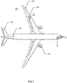
Figure 1 provides a schematic plan view of an aircraft comprising aircraft flow bodies according to embodiments of the present invention; -
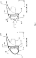
Figure 2 provides a pair of schematic cross-sectional views vertically through the line A-A of the aircraft flow body ofFigure 1 . - With reference to
figures 1 , anaircraft 100 is shown comprising a plurality of flow bodies such as thewing 101,horizontal tail 103,vertical tail 105, andengine nacelle 107. Each flow body comprises an internal structure consisting of an outer skin attached to underlying spars and/or ribs and/or stiffeners. The aircraft comprises a set of orthogonal aircraft axes, comprising a longitudinal X axis, a lateral (spanwise) Y axis, and a vertical Z axis. The region of each flow body existing in the most positive X direction is commonly referred to as the leading edge region of the flow body and is most susceptible to impact from foreign objects travelling in the -X direction. Thewing 101 further comprises a plurality of smaller flow bodies in the form ofslats 109, which are movably attached the forward (leading edge) region of thewing 101. These are constructed in substantially the same way as the larger structures in that they comprise an outer skin attached to underlying spars and/or ribs and/or stiffeners. - With reference to
figures 2 , a non-impacted flow body in the form of aslat 200 is shown on the left hand side. - The
slat 200 comprises anouter skin 203 that bounds, and is fixedly attached to, arib 201 and aspar 204 that lie internally within it. Theouter skin 203 is formed from a thin sheet alloy aluminium material (e.g. 2024 series aluminium alloy material), but any suitable metallic or composite material may alternatively be used. Therib 201 comprises afirst rib portion 207 attached by alap joint 211 with a single row offasteners 213 to asecond rib portion 209. Thefirst rib portion 207 is attached to theouter skin 203 in the leadingedge region 205 by fasteners (not shown) and is formed from a thin sheet alloy aluminium material (e.g. 2024 series aluminium alloy material), but any suitable metallic or composite material may alternatively be used. Thesecond rib portion 209 is attached to thespar 204 aft of the leadingedge region 205 by fasteners (also not shown) and is formed from a thin sheet alloy aluminium material (e.g. 2024 series aluminium alloy material), but any suitable metallic or composite material may alternatively be used. Thesecond rib portion 209 comprises aconnection portion 215 that attaches to a slat kinematic system for moving theslat 200 in operation. Therib 201 is oriented substantially vertically in a plane lying parallel to the XZ plane. Thespar 204 is oriented substantially vertically in a plane lying parallel to the YZ plane and is constructed from a sheet aluminium alloy material (e.g. or 7010 series or 2014 series aluminium alloy), but any suitable metallic or composite material may alternatively be used. During normal operation of theslat 200, theouter skin 203 is subjected to aerodynamic pressure loads, which are transferred viaspar 204, therib 201 and the kinematic system to thewing 101. The components in theslat 200 i.e. theskin 203,rib 201 andspar 204, are also subjected to inertial loads caused by accelerations of theaircraft 101 during take-off, cruise and landing. In response to this loading the components elastically deform and deflect within predetermined limits that are pre-determined by each component's load amount, sectional properties and material mechanical properties. - Referring to the right hand side of
figure 2 , the non-impacted flow body shown on the left hand side is also shown in an impacted and plastically deformed scenario, where an impact load L acts against the leadingedge region 205 of theslat 200 in a -X direction. - The stiffness of the
outer skin 203 is equal to the stiffness of thefirst rib portion 207 at the location where impact load L exerts itself on the structure, such that theskin 203 andfirst rib portion 207 deform uniformly in reaction to the impact load L, as shown. The impact kinetic energy is absorbed by slat 200 through deformation of theskin 203 and thefirst rib portion 207, and not by thesecond rib portion 209 andspar 204, which remain only elastically deformed in response to the impact load. In the example shown, thelap joint 211 is not sheared, however for an impact of a higher impact energy, thelap joint 211 is configured to shear at a predetermined load level, which redistributes the load back to theskin 203, which may deform further. - The stiffness of the
first rib portion 207 may be tailored by changing the sectional properties of thefirst rib portion 207 or by choosing a material for thefirst rib portion 207 that has a lower mechanical stiffness in the direction of the applied loading or both. Where less deformation of theskin 203 is desired, for example to prevent rupture of theskin 203 e.g. adjacent to the attachment interface withrib 201, the stiffness of thefirst rib portion 207 may be reduced to a value less than the stiffness of theskin 203 but sufficient to support the loading otherwise experienced during normal operation. Similarly where more deformation of theskin 203 is desired, the stiffness of thefirst rib portion 207 may alternatively be increased to a value higher than the stiffness of theskin 203 but sufficient to support the loading experienced during normal operation. - While at least one exemplary embodiment of the present invention(s) is disclosed herein, it should be understood that modifications, substitutions and alternatives may be apparent to one of ordinary skill in the art and can be made without departing from the scope of this disclosure. For example, it should be appreciated that the
rib 201 may be a unitary component with the required stiffness, rather than arib 201 with separate portions. Therib 201 may further be attached to only theskin 203 or additional structural components than theskin 203 orspar 204. This disclosure is intended to cover any adaptations or variations of the exemplary embodiment(s). In addition, in this disclosure, the terms "comprise" or "comprising" do not exclude other elements or steps, the terms "a" or "one" do not exclude a plural number, and the term "or" means either or both. Furthermore, characteristics or steps which have been described may also be used in combination with other characteristics or steps and in any order unless the disclosure or context suggests otherwise. This disclosure hereby incorporates by reference the complete disclosure of any patent or application from which it claims benefit or priority.
Claims (6)
- A aircraft flow body comprising:a rib bounded by and fixedly attached to an outer skin;wherein the outer skin and the rib are configured to plastically deform when the outer skin is subjected to an impact load in a leading edge region of the flow body;wherein the stiffness of the outer skin is greater than or equal to the stiffness of the rib when deformed by the impact load L.
- An aircraft flow body according to claim 1 wherein the rib comprises a first rib portion and a second rib portion; wherein the first rib portion is attached to the outer skin in the leading edge region; wherein the stiffness of the outer skin is greater than or equal to the stiffness of the first rib portion when deformed by the impact load; and, wherein the first rib portion is attached to the second rib portion by a lap joint;
- An aircraft flow body according to any preceding claim wherein the lap joint is orientated substantially perpendicular to the direction of the impact load.
- An aircraft flow body according to any preceding claim wherein the lap joint comprises a single row of shear fasteners.
- An aircraft flow body according to any preceding claim wherein the first rib portion and second rib portion are formed from dissimilar materials.
- An aircraft comprising an aircraft flow body according to any preceding claim.
Applications Claiming Priority (1)
| Application Number | Priority Date | Filing Date | Title |
|---|---|---|---|
| GBGB1821332.2A GB201821332D0 (en) | 2018-12-31 | 2018-12-31 | Aircraft flow body |
Publications (1)
| Publication Number | Publication Date |
|---|---|
| EP3674203A1 true EP3674203A1 (en) | 2020-07-01 |
Family
ID=65364663
Family Applications (1)
| Application Number | Title | Priority Date | Filing Date |
|---|---|---|---|
| EP19216410.1A Withdrawn EP3674203A1 (en) | 2018-12-31 | 2019-12-16 | Aircraft flow body |
Country Status (4)
| Country | Link |
|---|---|
| US (1) | US20200207457A1 (en) |
| EP (1) | EP3674203A1 (en) |
| CN (1) | CN111470054A (en) |
| GB (1) | GB201821332D0 (en) |
Cited By (2)
| Publication number | Priority date | Publication date | Assignee | Title |
|---|---|---|---|---|
| US20240174344A1 (en) * | 2022-11-30 | 2024-05-30 | Airbus Operations Gmbh | Flow body for an aircraft with split ribs |
| EP4378825A1 (en) * | 2022-11-30 | 2024-06-05 | Airbus Operations GmbH | Movable flow body having a hybrid load introduction rib |
Citations (6)
| Publication number | Priority date | Publication date | Assignee | Title |
|---|---|---|---|---|
| US2233969A (en) * | 1938-12-30 | 1941-03-04 | Bell Aircraft Corp | Pressed wing rib |
| WO2005070762A1 (en) * | 2004-01-22 | 2005-08-04 | Sonaca S.A. | Mobile leading edge flap for a main wing of the aerofoils of an aircraft and main wing provided with such a flap |
| WO2005100152A1 (en) * | 2004-04-16 | 2005-10-27 | Airbus Deutschland Gmbh | Fairing for an aircraft structure |
| DE102005060958A1 (en) * | 2005-12-20 | 2007-06-21 | Airbus Deutschland Gmbh | Aircraft structure protection, against damage from birds in flight, is an outer skin of glass fiber reinforced aluminum with a hollow zone to allow skin distortion through an impact |
| EP2130762A2 (en) * | 2008-05-06 | 2009-12-09 | Alenia Aeronautica S.P.A. | Wing and empennage leading edge structure made of thermoplastic material with a stiffened double-shell configuration |
| EP3135578A1 (en) * | 2015-08-26 | 2017-03-01 | Mitsubishi Aircraft Corporation | Leading-edge structure for aircraft, wing for aircraft, and aircraft |
-
2018
- 2018-12-31 GB GBGB1821332.2A patent/GB201821332D0/en not_active Ceased
-
2019
- 2019-12-16 EP EP19216410.1A patent/EP3674203A1/en not_active Withdrawn
- 2019-12-23 US US16/725,276 patent/US20200207457A1/en not_active Abandoned
- 2019-12-31 CN CN201911408914.0A patent/CN111470054A/en active Pending
Patent Citations (6)
| Publication number | Priority date | Publication date | Assignee | Title |
|---|---|---|---|---|
| US2233969A (en) * | 1938-12-30 | 1941-03-04 | Bell Aircraft Corp | Pressed wing rib |
| WO2005070762A1 (en) * | 2004-01-22 | 2005-08-04 | Sonaca S.A. | Mobile leading edge flap for a main wing of the aerofoils of an aircraft and main wing provided with such a flap |
| WO2005100152A1 (en) * | 2004-04-16 | 2005-10-27 | Airbus Deutschland Gmbh | Fairing for an aircraft structure |
| DE102005060958A1 (en) * | 2005-12-20 | 2007-06-21 | Airbus Deutschland Gmbh | Aircraft structure protection, against damage from birds in flight, is an outer skin of glass fiber reinforced aluminum with a hollow zone to allow skin distortion through an impact |
| EP2130762A2 (en) * | 2008-05-06 | 2009-12-09 | Alenia Aeronautica S.P.A. | Wing and empennage leading edge structure made of thermoplastic material with a stiffened double-shell configuration |
| EP3135578A1 (en) * | 2015-08-26 | 2017-03-01 | Mitsubishi Aircraft Corporation | Leading-edge structure for aircraft, wing for aircraft, and aircraft |
Cited By (2)
| Publication number | Priority date | Publication date | Assignee | Title |
|---|---|---|---|---|
| US20240174344A1 (en) * | 2022-11-30 | 2024-05-30 | Airbus Operations Gmbh | Flow body for an aircraft with split ribs |
| EP4378825A1 (en) * | 2022-11-30 | 2024-06-05 | Airbus Operations GmbH | Movable flow body having a hybrid load introduction rib |
Also Published As
| Publication number | Publication date |
|---|---|
| CN111470054A (en) | 2020-07-31 |
| US20200207457A1 (en) | 2020-07-02 |
| GB201821332D0 (en) | 2019-02-13 |
Similar Documents
| Publication | Publication Date | Title |
|---|---|---|
| US8066222B2 (en) | Energy absorbing impact band | |
| Schijve | Multiple‐site damage in aircraft fuselage structures | |
| Reckzeh | Aerodynamic design of the high-lift-wing for a Megaliner aircraft | |
| EP3318481B1 (en) | Panel structure for an aircraft and manufacturing method thereof | |
| RU2667437C2 (en) | Winglet attach fitting and method for attaching split winglet to wing | |
| EP3326905B1 (en) | Drag neutral vehicle window | |
| US11059563B2 (en) | Collapsible flap deployment system for a wing of an aircraft | |
| EP2610164A1 (en) | Aircraft with fuselage-mounted engines and an internal shield | |
| US20090127392A1 (en) | Protection device | |
| EP3031711A1 (en) | Aircraft frame for tailstrike angle enhancement | |
| EP3135578B1 (en) | Leading-edge structure for aircraft, wing for aircraft, and aircraft | |
| EP3674203A1 (en) | Aircraft flow body | |
| EP1475304B1 (en) | Aircraft wing | |
| EP2514671A1 (en) | Device for protecting sensitive areas against the impact of foreign objects | |
| EP3838744A1 (en) | Leading edge for an airfoil | |
| US9573672B2 (en) | Device for protecting the front spar structure of a central casing of an aircraft wing and at least one piece of equipment located in said wing | |
| US11873095B2 (en) | Leading-edge component for an aircraft | |
| EP2881318A1 (en) | Aircraft fuselage | |
| US11027823B2 (en) | Holding device for an aircraft actuator | |
| US12172745B2 (en) | Energy attenuating aircraft windshield corner supports, systems and methods | |
| US11230365B2 (en) | Leading-edge component for an aircraft | |
| EP4257480A1 (en) | Wing-box structure | |
| Sturgeon | Toward a laminar-flow-control transport | |
| CN116853509A (en) | A method for arranging an integral fuel tank of an aircraft | |
| Rich | Vulnerability and Crashworthiness in the Design of Rotary Wing Vehicle Structures |
Legal Events
| Date | Code | Title | Description |
|---|---|---|---|
| PUAI | Public reference made under article 153(3) epc to a published international application that has entered the european phase |
Free format text: ORIGINAL CODE: 0009012 |
|
| STAA | Information on the status of an ep patent application or granted ep patent |
Free format text: STATUS: THE APPLICATION HAS BEEN PUBLISHED |
|
| AK | Designated contracting states |
Kind code of ref document: A1 Designated state(s): AL AT BE BG CH CY CZ DE DK EE ES FI FR GB GR HR HU IE IS IT LI LT LU LV MC MK MT NL NO PL PT RO RS SE SI SK SM TR |
|
| AX | Request for extension of the european patent |
Extension state: BA ME |
|
| STAA | Information on the status of an ep patent application or granted ep patent |
Free format text: STATUS: REQUEST FOR EXAMINATION WAS MADE |
|
| 17P | Request for examination filed |
Effective date: 20210111 |
|
| RBV | Designated contracting states (corrected) |
Designated state(s): AL AT BE BG CH CY CZ DE DK EE ES FI FR GB GR HR HU IE IS IT LI LT LU LV MC MK MT NL NO PL PT RO RS SE SI SK SM TR |
|
| STAA | Information on the status of an ep patent application or granted ep patent |
Free format text: STATUS: THE APPLICATION IS DEEMED TO BE WITHDRAWN |
|
| 18D | Application deemed to be withdrawn |
Effective date: 20210112 |