EP3674121B1 - Electric work vehicle - Google Patents
Electric work vehicle Download PDFInfo
- Publication number
- EP3674121B1 EP3674121B1 EP19208953.0A EP19208953A EP3674121B1 EP 3674121 B1 EP3674121 B1 EP 3674121B1 EP 19208953 A EP19208953 A EP 19208953A EP 3674121 B1 EP3674121 B1 EP 3674121B1
- Authority
- EP
- European Patent Office
- Prior art keywords
- electric motor
- machine body
- support frame
- frame
- frames
- Prior art date
- Legal status (The legal status is an assumption and is not a legal conclusion. Google has not performed a legal analysis and makes no representation as to the accuracy of the status listed.)
- Active
Links
Images








Classifications
-
- B—PERFORMING OPERATIONS; TRANSPORTING
- B60—VEHICLES IN GENERAL
- B60K—ARRANGEMENT OR MOUNTING OF PROPULSION UNITS OR OF TRANSMISSIONS IN VEHICLES; ARRANGEMENT OR MOUNTING OF PLURAL DIVERSE PRIME-MOVERS IN VEHICLES; AUXILIARY DRIVES FOR VEHICLES; INSTRUMENTATION OR DASHBOARDS FOR VEHICLES; ARRANGEMENTS IN CONNECTION WITH COOLING, AIR INTAKE, GAS EXHAUST OR FUEL SUPPLY OF PROPULSION UNITS IN VEHICLES
- B60K1/00—Arrangement or mounting of electrical propulsion units
- B60K1/04—Arrangement or mounting of electrical propulsion units of the electric storage means for propulsion
-
- B—PERFORMING OPERATIONS; TRANSPORTING
- B60—VEHICLES IN GENERAL
- B60K—ARRANGEMENT OR MOUNTING OF PROPULSION UNITS OR OF TRANSMISSIONS IN VEHICLES; ARRANGEMENT OR MOUNTING OF PLURAL DIVERSE PRIME-MOVERS IN VEHICLES; AUXILIARY DRIVES FOR VEHICLES; INSTRUMENTATION OR DASHBOARDS FOR VEHICLES; ARRANGEMENTS IN CONNECTION WITH COOLING, AIR INTAKE, GAS EXHAUST OR FUEL SUPPLY OF PROPULSION UNITS IN VEHICLES
- B60K1/00—Arrangement or mounting of electrical propulsion units
-
- B—PERFORMING OPERATIONS; TRANSPORTING
- B60—VEHICLES IN GENERAL
- B60L—PROPULSION OF ELECTRICALLY-PROPELLED VEHICLES; SUPPLYING ELECTRIC POWER FOR AUXILIARY EQUIPMENT OF ELECTRICALLY-PROPELLED VEHICLES; ELECTRODYNAMIC BRAKE SYSTEMS FOR VEHICLES IN GENERAL; MAGNETIC SUSPENSION OR LEVITATION FOR VEHICLES; MONITORING OPERATING VARIABLES OF ELECTRICALLY-PROPELLED VEHICLES; ELECTRIC SAFETY DEVICES FOR ELECTRICALLY-PROPELLED VEHICLES
- B60L50/00—Electric propulsion with power supplied within the vehicle
- B60L50/50—Electric propulsion with power supplied within the vehicle using propulsion power supplied by batteries or fuel cells
-
- B—PERFORMING OPERATIONS; TRANSPORTING
- B62—LAND VEHICLES FOR TRAVELLING OTHERWISE THAN ON RAILS
- B62D—MOTOR VEHICLES; TRAILERS
- B62D21/00—Understructures, i.e. chassis frame on which a vehicle body may be mounted
- B62D21/15—Understructures, i.e. chassis frame on which a vehicle body may be mounted having impact absorbing means, e.g. a frame designed to permanently or temporarily change shape or dimension upon impact with another body
- B62D21/152—Front or rear frames
-
- B—PERFORMING OPERATIONS; TRANSPORTING
- B62—LAND VEHICLES FOR TRAVELLING OTHERWISE THAN ON RAILS
- B62D—MOTOR VEHICLES; TRAILERS
- B62D25/00—Superstructure or monocoque structure sub-units; Parts or details thereof not otherwise provided for
- B62D25/08—Front or rear portions
-
- B—PERFORMING OPERATIONS; TRANSPORTING
- B60—VEHICLES IN GENERAL
- B60K—ARRANGEMENT OR MOUNTING OF PROPULSION UNITS OR OF TRANSMISSIONS IN VEHICLES; ARRANGEMENT OR MOUNTING OF PLURAL DIVERSE PRIME-MOVERS IN VEHICLES; AUXILIARY DRIVES FOR VEHICLES; INSTRUMENTATION OR DASHBOARDS FOR VEHICLES; ARRANGEMENTS IN CONNECTION WITH COOLING, AIR INTAKE, GAS EXHAUST OR FUEL SUPPLY OF PROPULSION UNITS IN VEHICLES
- B60K1/00—Arrangement or mounting of electrical propulsion units
- B60K2001/001—Arrangement or mounting of electrical propulsion units one motor mounted on a propulsion axle for rotating right and left wheels of this axle
-
- B—PERFORMING OPERATIONS; TRANSPORTING
- B60—VEHICLES IN GENERAL
- B60K—ARRANGEMENT OR MOUNTING OF PROPULSION UNITS OR OF TRANSMISSIONS IN VEHICLES; ARRANGEMENT OR MOUNTING OF PLURAL DIVERSE PRIME-MOVERS IN VEHICLES; AUXILIARY DRIVES FOR VEHICLES; INSTRUMENTATION OR DASHBOARDS FOR VEHICLES; ARRANGEMENTS IN CONNECTION WITH COOLING, AIR INTAKE, GAS EXHAUST OR FUEL SUPPLY OF PROPULSION UNITS IN VEHICLES
- B60K1/00—Arrangement or mounting of electrical propulsion units
- B60K1/04—Arrangement or mounting of electrical propulsion units of the electric storage means for propulsion
- B60K2001/0405—Arrangement or mounting of electrical propulsion units of the electric storage means for propulsion characterised by their position
- B60K2001/0411—Arrangement in the front part of the vehicle
-
- B—PERFORMING OPERATIONS; TRANSPORTING
- B60—VEHICLES IN GENERAL
- B60K—ARRANGEMENT OR MOUNTING OF PROPULSION UNITS OR OF TRANSMISSIONS IN VEHICLES; ARRANGEMENT OR MOUNTING OF PLURAL DIVERSE PRIME-MOVERS IN VEHICLES; AUXILIARY DRIVES FOR VEHICLES; INSTRUMENTATION OR DASHBOARDS FOR VEHICLES; ARRANGEMENTS IN CONNECTION WITH COOLING, AIR INTAKE, GAS EXHAUST OR FUEL SUPPLY OF PROPULSION UNITS IN VEHICLES
- B60K25/00—Auxiliary drives
- B60K2025/005—Auxiliary drives driven by electric motors forming part of the propulsion unit
-
- B—PERFORMING OPERATIONS; TRANSPORTING
- B60—VEHICLES IN GENERAL
- B60K—ARRANGEMENT OR MOUNTING OF PROPULSION UNITS OR OF TRANSMISSIONS IN VEHICLES; ARRANGEMENT OR MOUNTING OF PLURAL DIVERSE PRIME-MOVERS IN VEHICLES; AUXILIARY DRIVES FOR VEHICLES; INSTRUMENTATION OR DASHBOARDS FOR VEHICLES; ARRANGEMENTS IN CONNECTION WITH COOLING, AIR INTAKE, GAS EXHAUST OR FUEL SUPPLY OF PROPULSION UNITS IN VEHICLES
- B60K25/00—Auxiliary drives
-
- B—PERFORMING OPERATIONS; TRANSPORTING
- B60—VEHICLES IN GENERAL
- B60Y—INDEXING SCHEME RELATING TO ASPECTS CROSS-CUTTING VEHICLE TECHNOLOGY
- B60Y2200/00—Type of vehicle
- B60Y2200/20—Off-Road Vehicles
- B60Y2200/22—Agricultural vehicles
-
- Y—GENERAL TAGGING OF NEW TECHNOLOGICAL DEVELOPMENTS; GENERAL TAGGING OF CROSS-SECTIONAL TECHNOLOGIES SPANNING OVER SEVERAL SECTIONS OF THE IPC; TECHNICAL SUBJECTS COVERED BY FORMER USPC CROSS-REFERENCE ART COLLECTIONS [XRACs] AND DIGESTS
- Y02—TECHNOLOGIES OR APPLICATIONS FOR MITIGATION OR ADAPTATION AGAINST CLIMATE CHANGE
- Y02T—CLIMATE CHANGE MITIGATION TECHNOLOGIES RELATED TO TRANSPORTATION
- Y02T10/00—Road transport of goods or passengers
- Y02T10/60—Other road transportation technologies with climate change mitigation effect
- Y02T10/70—Energy storage systems for electromobility, e.g. batteries
Definitions
- This invention relates to an electric work vehicle which employs an electric motor as a prime mover.
- JP 2017-024710 A discloses a riding electric tractor as an example of an electric work vehicle.
- a riding electric tractor In its configuration, right and left machine body frames are provided, and an electric motor is supported to front portions of the machine body frames.
- An output shaft of the electric motor protrudes rearwards.
- a transmission shaft coupled to the output shaft of the electric motor extends to the rear side to be coupled to an input shaft of a transmission case.
- a PTO shaft is mounted to protrude rearwards. Power taken off the speed changer device is transmitted to this PTO shaft. Then, the power from the PTO shaft is transmitted to a rotary cultivator mounted at a rear portion of the electric tractor, thus driving the rotary cultivator.
- JP 2017-024710 A it is assumed that an implement such as the rotary cultivator is mounted at a rear portion of the transmission case. So, in order to transmit power to this implement mounted at a rear portion of the electric tractor, the PTO shaft is arranged to protrude rearwards, at the rear portion of the transmission case.
- the electric motor is supported to front portions of the right and left machine body frames. Also, a front support frame and a rear support frame are disposed with a space in the front/rear direction therebetween and connected to/between the front portions of the right and left machine body frames.
- the electric motor is disposed between the right and left machine body frames.
- a rear portion of the electric motor is bolt-connected to the rear support frame, a front portion of the electric motor is bolt-connected to the front support frame, and a right portion and a left portion of the electric motor are placed in contact with the right and left frame body frames.
- JP 2017-024710 A since the implement such as the rotary cultivator is supported to rear portions of the machine body frames, the front/rear balance of the electric work vehicle is adjusted by attaching a balance weight to a front portion of the machine body frames.
- JP 2017-024710 A there are provided the right and left machine body frames and to the front portions of the machine body frames, an electric motor as a prime mover for the implement or a prime mover for traveling is supported. And, the output shaft of the electric motor is arranged to extend rearwards and the transmission shaft for transmitting power to the transmission case is connected via a coupling to the output shaft of the electric motor.
- JP 2013 248918 discloses an electric work vehicle according to the preamble of claim 1.
- JP 2015 054620 discloses an electric vehicle with a rear deck.
- US 2018/026244 discloses an electric work vehicle.
- An electric work vehicle comprising: front wheels and rear wheels for traveling:
- power of the electric motor can be transmitted to the implement, in appropriate correspondence with both the situation of the implement being mounted between the front wheels and the rear wheels and the situation of the implement being mounted to front portions of the machine body frames.
- the working efficiency of the electric work vehicle can be improved.
- An upper end portion of the electric motor may be disposed at a position lower than upper end portions of the front portions of the machine body frames, as seen in a side view.
- a lower end portion of the electric motor may be disposed at a position lower than lower end portions of the front portions of the machine body frames, as seen in a side view.
- a rotational axis of the front wheels may be disposed at a position lower than lower end portions of the front portions of the machine body frames, as seen in a side view; and the lower end portion of the electric motor is disposed at a position lower than the rotational axis of the front wheels, as seen in a side view.
- Axes of the front output shaft and the rear output shaft of the electric motor may be disposed at positions which are lower than the upper end portions of the front portions of the machine body frames and which also are higher than the rotational axis of the front wheels.
- the motor can be disposed at a favorable position, with consideration to favorable balance between the respect of gravity center lowering and the respect of ensuring a minimal ground clearance for the electric work vehicle.
- An electric work vehicle comprising:
- the support frame is connected to/between the front portions of the right and left machine body frames
- the electric motor is connected to the support frame, and this electric motor is supported via the support frame to the right and left machine body frames.
- An upper end portion of the electric motor may be disposed at a position lower than upper end portions of the front portions of the machine body frames, as seen in a side view.
- a lower end portion of the electric motor may bes disposed at a position higher than lower end portions of the front portions of the machine body frame as seen in a side view.
- the electric work vehicle further comprises:
- the front reinforcement frame and the reinforcement frames are disposed to surround the electric motor and connected to the front portions of the right and left machine body frames.
- the front reinforcement frame and the reinforcement frames the front portions of the machine body frames and the vicinity of the support frame are reinforced, so that supporting strength of the electric motor can be achieved.
- the reinforcement frames and the electric motor are spaced apart from each other in the right/left direction as seen in the plan view. This arrangement serves to facilitate flow of air between the reinforcement frames and the electric motor, thus being advantageous in the respect of promotion of heat discharge of the electric motor.
- the space between the reinforcement frames and the electric motor can be utilized, so that such harness and/or cooling hose can be disposed easily and smoothly.
- the electric work vehicle further comprises:
- the front reinforcement frame, the upper reinforcement frames and the lower reinforcement frames are disposed to surround the electric motor and connected to the front portions of the right and left machine body frames.
- the front reinforcement frame, the upper reinforcement frames and the lower reinforcement frames, the front portions of the machine body frames and the vicinity of the support frame are reinforced, so that supporting strength of the electric motor can be achieved.
- the upper reinforcement frames, the lower reinforcement frames and the electric motor are spaced apart from each other in the right/left direction as seen in the plan view. This arrangement serves to facilitate flow of air between the upper reinforcement frames, the lower reinforcement frames and the electric motor, thus being advantageous in the respect of promotion of heat discharge of the electric motor.
- the space between the upper reinforcement frames, the lower reinforcement frames and the electric motor can be effectively utilized, so that such harness and/or cooling hose can be disposed easily and smoothly.
- the upper reinforcement frames and the lower reinforcement frames may be disposed with a predetermined space therebetween as seen in the side view.
- the upper reinforcement frames and the lower reinforcement frames are spaced apart from each other in the vertical direction as seen in the side view. With this, air can flow easily between the upper reinforcement frames and the lower reinforcement frames, thus being advantageous in the respect of heat discharge of the electric motor.
- the space between the upper reinforcement frames and the lower reinforcement frames can be effectively utilized, so that such harness and/or cooling hose can be disposed easily and smoothly.
- a front portion of the electric motor may be connected to the front reinforcement frame.
- the electric motor in addition to the electric motor being supported via the support frame to the right and left machine body frames, the electric motor is supported also the front reinforcement frame and the reinforcement frames (the upper reinforcement frames, the lower reinforcement frames), improvement of the supporting strength of the electric motor can be achieved.
- the front transmission shaft for transmitting power is supported to the right and left machine body frames via the support member and the front support frame. No change occurs in the position of the transmission shaft. Under this condition, by simply connecting the output shaft of the electric motor to the portion of the front transmission shaft supported to the support member, the output shaft of the electric motor can be connected to the front transmission shaft smoothly and easily.
- the front support frame connected to/between the right and left machine body frames provides the function as a reinforcement member for the right and left machine body frames, in addition to the function of supporting the support member (the front transmission shaft).
- the front support frame provides also the function as a reinforcement member for the right and left machine body frames, thus being advantageous with respect to improvement of the strength of the front portions of the right and left machine body frames.
- the electric work vehicle further comprises a motor frame connected to/between a portion of the electric motor opposite to the output shaft and the right and left machine of improvement of the strength of the front portions of the right and left machine body frames.
- the electric work vehicle further comprises:
- the front transmission shaft acts also as a support member for the front wheel support frame. So, this configuration is advantageous for configuration simplification.
- the supporting strength of the front transmission shaft is high.
- the front wheel support frame is rollably supported to the portion of the front transmission shaft located between the front support frame and the rear support frame, the supporting strength of the front wheel support frame is also high.
- a cutout portion that allows rolling movement of the front wheel support frame with introduction of the front wheel support frame therein may be provided in the right/left machine body frame.
- a sign “F” denotes "front direction”
- a sign “B” denotes “rear direction”
- a sign “U” denotes an upper direction
- a sign “D” denotes “lower direction”
- a sign “R” denotes “right direction”
- a sign “L” denotes "left direction”, respectively.
- right and left machine body frames 3 are disposed along the front/rear direction, and at front portions of the machine body frames 3, right and left front wheels 1 are supported; and at rear portions of the machine body frames 3, right and left rear wheels 2 are supported.
- a driving section 4 is supported.
- a mower 5 is supported.
- a rollover protection structure (ROPS) frame 6 is provided at rear portions of the machine body frames 3 and a grass collecting section 7 is supported to this ROPS frame 6.
- a transmission case 8 is connected; and to this transmission case 8, the right and left rear wheels 2 are supported.
- An electric motor 9 for traveling is disposed under a rear orientation and connected to a front portion of the transmission case 8. With power from the electric motor 9, the rear wheels 2 are driven.
- the ROPS frame 6 To a rear portion of the transmission case 8, the ROPS frame 6 is connected. A driver's seat 10 and a steering wheel 11 for steering the front wheels 1 are provided in the driving section 4.
- the mower 5 is of a type in which three blades (not shown) rotatably driven about vertical axes are disposed side by side along the right/left direction.
- Front portions of right and left support links 12 are supported to be vertically pivotable about axes extending in the right/left direction of the machine body frames 3.
- the support links 12 extend rearwards and the mower 5 is connected to rear portions of the support links 12.
- right and left support brackets 41 are connected to front portions of the machine body frames 3, and an operational shaft 34 is rotatably supported to/between the support brackets 41.
- an operational shaft 34 is rotatably supported to/between the support brackets 41.
- hook-like support members 34a are connected to a right end portion and a left end portion of the operational shaft 34, and an operational lever 34b is connected to the left support member 34a.
- support links 36 are connected and extend rearwards.
- the condition illustrated in Figs. 2 , 3 and 4 is a condition in which the right portion and the left portion of the support shaft 35 are rotatably supported to the support members 34a of the operational shafts 34 and the support links 36 extend rearwards to be connected to the mower 5.
- FIG. 2 vertically pivotable right and left operational arms 13 are provided and lift cylinders 14 are provided for pivotally operating the operational arms 13.
- a coupling link 15 is connected to/between the respective operational arm 13 and the rear portion of the respective support link 12. In operation, as the respective operational arm 13 is pivotally operated vertically by the lift cylinder 14, the mower 5 is lifted up/down.
- an electric motor 16 for driving the mower 5 is supported to front portions of the machine body frames 3 to be located forwardly of the front wheels 1 as seen in a side view.
- a battery 17 for supplying electric power to the electric motors 9, 16 is supported to an upper portion of the front portions of the machine body frames 3.
- the electric motor 16 is provided with its front output shaft 16b protruding forwards and its rear output shaft 16a protruding rearwards.
- the condition shown in Figs. 1 through 5 is a condition in which a cover 37 is attached for covering the front output shaft 16b of the electric motor 16.
- a support frame 18 in the form of a flat plate is connected to/between front portions of the right and left machine body frames 3.
- a support member 19 in the form of an angular tube is bolt-connected to protrude forwards from the support frame 18.
- a support frame 20 in the form of a flat plate is connected to/between front portions of the right and left machine body frames 3 and is disposed on the rear side of the support frame 18.
- a support frame 38 is connected to/between upper portions of the front end portions of the right and left machine body frames 3.
- a connecting member 28 formed by bending a flat plate is connected to the support frame 38 with bolts 39.
- a front transmission shaft 21 is disposed along the front/rear direction, wherein a front portion of this front transmission shaft 21 is rotatably supported by a bearing 23 inside the support member 19, and a rear portion of the front transmission shaft 21 is rotatably supported by a bearing 24 to the support frame 20.
- An input case 22 for transmitting power to the blades of the mower 5 is provided at the right/left center portion of the mower 5 and an input shaft 22a of the input case 22 extends forwards.
- a front end portion of a rear transmission shaft 25 is connected via a universal joint 26 and a rear end portion of the rear transmission shaft 25 is connected to the input shaft 22a of the input case 22 via the universal joint 26.
- the connecting member 28 will be detached from the support frame 38. Then, by operating the operational lever 34b of the operational shaft 34 forwards, the support member 34a of the operational shaft 34 is operated to the front side, whereby the support shaft 35 and the support link 36 will be detached from the support member 34a of the operational shaft 34.
- the electric motor 16 will be passed between the front portions of the right and left machine body frames 3 (between the right and left support brackets 41), and passed between the support frame 28 and the operational shaft 34.
- the rear output shaft 16a of the electric motor 16 will be inserted into the support member 19. Inside the support member 19, to the portion of the front transmission shaft 21 supported to the support member 19 (bearing 23), the rear output shaft 16a of the electric motor 16 will be connected. The rear output shaft 16a of the electric motor 16 and the front output shaft 21 are connected via a spline arrangement.
- the portion of the electric motor 16 on the side of the rear output shaft 16a will be connected to the front end portion (flange portion 19a) of the support member 19; and the support frame 18 and the portion of the electric motor 16 on the side of the rear output shaft 16a will be disposed with a space therebetween that corresponds to the length of the support member 19.
- the connecting member 28 After establishment of connection between the portion of the electric motor 16 on the side of the rear output shaft 16a and the flange portion 19a of the support member 19, the connecting member 28 will be connected to the support frame 38 with the bolts 39 and the connecting member 28 will be connected to an upper portion of the portion of the electric motor 16 on the side of the front output shaft 16b (cover 37) with bolts 40.
- the support shaft 35 and the support links 36 will be attached as shown in Figs. 1 through 4 .
- the electric motor 16 is supported to the right and left machine body frames 3 via the support member 19 and the support frame 18 and supported to the right and left machine body frames 3 via the connecting member 28 and the support frame 38.
- an upper end portion 16c of the electric motor 16 is disposed at a position lower than an upper end portion 3b of the front portion of the machine body frame 3 as seen in the side view.
- a lower end portion 16d of the electric motor 16 is disposed at a position lower than the lower end portion 3c of the front portion of the machine body frame 3 as seen in the side view.
- a rotational axis P1 of the front wheel 1 (the front wheel support portion 30) is disposed at a position lower than the lower end portion 3c of the front portion of the machine body frame 3 as seen in the side view; and the lower end portion 16d of the electric motor 16 is disposed at a position lower than the rotational axis P1 of the front wheel 1 (front wheel support portion 30) as seen in the side view.
- the condition illustrated in Figs. 1 through 5 is a condition in which power of the electric motor 16 (rear output shaft 16a) is transmitted to the mower 5 mounted between the front wheels 1 and the rear wheels 2.
- the mower 5 is not mounted between the front wheels 1 and the rear wheels 2, but this mower 5 is to be mounted to front portions of the machine body frames 3 or a different implement (not shown) is to be mounted to the front portions of the machine body frames 3, the rear transmission shaft 25 and the universal joint 26 shown in Figs. 3 and 5 will be detached and a cover (not shown) for covering the rear portion of the front transmission shaft 21 will be attached.
- the cover 37 shown in Figs. 1-5 will be detached; instead, a transmission shaft (not shown) will be connected to/between an input shaft (not shown) of the mower 5 mounted to the front portions of the machine body frames 3 or an input shaft (not shown) of the different implement and the front output shaft 16b of the electric motor 16.
- a front wheel support frame 29 to which the right and left front wheels 1 are supported to be steerable.
- Right and left front wheel support portions 30 supporting the front wheels 1 are supported to a right portion and a left portion of the front wheel support frame 29 to be steerable.
- a steering rod 31 operated along the front/rear direction by the steering wheel 11 is connected to a knuckle arm 30a of the left front wheel support portion 30; and to/between the right and left front wheel support portions 30, a tie rod 32 is connected.
- the tie rod 32 passes under the machine body frames 3 and under the universal joint 26 connecting the front transmission shaft 21 with the rear transmission shaft 25.
- the steering rod 31 is operated in the front/rear direction, whereby the front wheels 1 (front wheel support portions 30) are steered by the knuckle arm 30a of the left front wheel support portion 30 and the tie rod 32.
- a cylindrical boss portion 29a is connected to the right/left center portion of the front wheel support frame 29.
- a boss portion 29a of the front wheel support frame 29 is rotatably engaged and this front wheel support frame 29 is rollably supported to the front transmission shaft 21 to be capable of rolling.
- the right and left machine body frames 3 respectively defines a cutout portion 3a which is opened downwards, and as the front wheel support frame 29 is fitted into the cutout portion 3a of the machine body frame 3 from the underside, rolling action of the front wheel support frame 29 is allowed.
- the positions at which the front wheel support frame 29 comes into abutment against an upper side portion of the cutout portion 3a of the machine body frame 3 are right and left limit positions of rolling of the front wheel support frame 29.
- the support frame 18 is connected along the vertical direction to follow the cutout portion 3a of the machine body frame 3.
- the support frame 20 is connected along the vertical direction to follow the cutout portion 3a of the machine body frame 3.
- right and left machine body frames 103 are disposed along the front/rear direction, and at front portions of the machine body frames 103, right and left front wheels 101 (corresponding to a "traveling device") are supported, and at rear portions of the machine body frames 103, right and left rear wheels 102 (corresponding to a "traveling device”) are supported.
- a driving section 104 is supported.
- a mower 105 (corresponding to an "implement") is supported.
- a ROPS frame 106 is provided at rear portions of the machine body frames 103 and a grass collecting section 107 is supported to this ROPS frame 106.
- a transmission case 108 is connected and to this transmission case 108, the right and left rear wheels 102 are supported.
- An electric motor 109 for traveling is disposed under a rear orientation and connected to a front portion of the transmission case 108. With power from the electric motor 109, the rear wheels 102 are driven.
- the ROPS frame 106 To a rear portion of the transmission case 108, the ROPS frame 106 is connected. A driver's seat 110 and a steering wheel 111 for steering the front wheels 101 are provided in the driving section 104.
- the mower 105 is of a type in which three blades (not shown) rotatably driven about vertical axes are disposed side by side along the right/left direction.
- Front portions of right and left support links 112 are supported to be vertically pivotable about axes extending in the right/left direction of the machine body frames 103.
- the support links 112 extend rearwards and the mower 105 is connected to rear portions of the support links 112.
- right and left upper reinforcement frames 140 are connected to front portions of the machine body frames 103; and right and left support brackets 145 are connected to the upper reinforcement frames 140.
- Right and left support brackets 145 are connected to the upper reinforcement frames 140.
- right and left support links 146 are connected to be vertically pivotable and extend rearwards. And, to rear portions of the support links 146, the mower 105 is connected.
- a support frame 118 in the form of a flat plate is connected, and to a flange portion 118a of the front face portion of the support frame 118, a support member 119 in the form of an angular tube is bolt-connected to protrude forwards from the support frame 118.
- a support frame 120 in the form of a flat plate is connected to/between the front portions of the right and left machine body frames 103.
- a front transmission shaft 121 is disposed along the front/rear direction and a front portion of this front transmission shaft 121 is rotatably supported by a bearing 123 inside the support member 119; and a rear portion of the front transmission shaft 121 is rotatably supported by a bearing 124 to the support frame 120.
- An input case 122 for transmitting power to the blades of the mower 105 is provided at the right/left center portion of the mower 105 and an input shaft 122a of the input case 122 extends forwards.
- a rear end portion of a rear transmission shaft 125 is connected via a universal joint 126 and a rear end portion of the rear transmission shaft 125 is connected to the input shaft 122a of the input case 122 via the universal joint 126.
- a support frame 128 in the form of a flat plate is connected with bolts 134, 135, 136.
- the center portion of the support frame 128 is placed in contact with the front end portion of the support member 119, and an opening 128a is formed at the center portion of the support frame 128.
- right and left upper reinforcement frames 140 are connected with bolts 135, 137 to upper portions of front portions of the right and left machine body frames 103 and extend to protrude forwards from the front end portions of the machine body frames 103.
- the support frame 128 and the upper reinforcement frames 140 are connected under temporarily mutually fastened states to the machine body frames 103.
- Right and left lower reinforcement frames 141 are connected with bolts 136, 138 to lower portions of the front portions of the right and left machine body frames 103 and extend to protrude forwards from the front end portions of the machine body frames 103. With the bolts 136, the support frame 128 and the lower reinforcement frames 141 are connected under temporarily mutually fastened states to the machine body frames 103.
- a front reinforcement frame 142 in the form of a flat plate is connected with bolts 139 to/between the front portions of the right and left upper reinforcement frames 140 and the front portions of the right and left lower reinforcement frames 141.
- support brackets 145 are connected to the upper reinforcement frames 140.
- a front wheel support frame 129 to which the right and left front wheels 101 are supported to be steerable.
- Right and left front wheel support portions 130 supporting the front wheels 101 are supported to a right portion and a left portion of the front wheel support frame 129 to be steerable.
- a steering rod 131 operated along the front/rear direction by the steering wheel 111 is connected to a knuckle arm 130a of the left front wheel support portion 130 and to/between the right and left front wheel support portions 130, a tie rod 132 is connected.
- the tie rod 132 passes through an opening 103b of the machine body frame 103, and passes under the universal joint 126 connecting the front transmission shaft 121 with the rear transmission shaft 125.
- the steering rod 131 is operated in the front/rear direction, whereby the front wheels 101 (front wheel support portions 130) are steered by the knuckle arm 130a of the left front wheel support portion 130 and the tie rod 132.
- a cylindrical boss portion 129a is connected to the right/left center portion of the front wheel support frame 129.
- a boss portion 129a of the front wheel support frame 129 is rotatably engaged; and this front wheel support frame 129 is rollably supported to the front transmission shaft 121 to be capable of rolling.
- the right and left machine body frames 103 respectively defines a cutout portion 103a which is opened downwards, and as the front wheel support frame 129 is fitted into the cutout portion 3a of the machine body frame 103 from the underside, rolling action of the front wheel support frame 129 is allowed.
- the positions at which the front wheel support frame 129 comes into abutment against an upper side portion of the cutout portion 103a of the machine body frame 103 are right and left limit positions of rolling of the front wheel support frame 129.
- the support frame 118 is connected along the vertical direction to follow the cutout portion 103a of the machine body frame 103.
- the support frame 120 is connected along the vertical direction to follow the cutout portion 103a of the machine body frame 103.
- an electric motor 116 for driving the mower 105 is provided.
- a battery 117 for supplying electric power to the electric motors 109, 116 is supported to an upper portion of the front portions of the machine body frames 103 and supported to upper portions of the upper reinforcement frames 140.
- the electric motor 116 will be inserted between the right and left upper reinforcement frames 140 and between the right and left lower reinforcement frames 141, with the output shaft 116a of this electric motor 116 being oriented rearwards.
- the output shaft 116a of the electric motor 116 When the output shaft 116a of the electric motor 116 is inserted into the support member 119 through the openings 128a of the support frames 128, inside the support member 119, the output shaft 116a of the electric motor 116 will be connected to the portion of the front transmission shaft 121 which portion is supported to the support member 119 (bearing 123).
- the output shaft 116a of the electric motor 116 and the front transmission shaft 121 are connected via a spline arrangement.
- the portion of the electric motor 116 on the side of the output shaft 116a will be connected to the support member 128 (the flange portion 119a of the support member 119) and the electric motor 116 will be supported to the right and left machine body frames 103 via the support frame 128, the support member 119 and the support frame 118.
- the front reinforcement frame 142 is connected to the upper reinforcement frames 140 and the lower reinforcement frames 141 with the bolts 139, the front reinforcement frame 142 is disposed forwardly of the electric motor 116.
- the support link 146 as shown in Fig. 6 and Fig. 7 , will be attached to/between the support bracket 145 and the mower 105.
- Power of the electric motor 116 is transmitted to the input shaft 122a of the input case 122 from the output shaft 116a of the electric motor 116, via the front transmission shaft 121 and the rear transmission shaft 125.
- cut grass pieces cut by the mower 105 will be conveyed and fed to the grass collecting portion 107 through a duct 133 disposed on the lateral side of the electric motor 109 and the upper side of the transmission case 108.
- the electric motor 116 protrudes forwardly from the front end portions of the machine body frames 103 as seen in the side view and is positioned on the front side of the front wheels 101.
- An upper end portion 116b of the electric motor 116 is disposed at a position lower than the upper end portion 103c of the front portion of the machine body frame 103 as seen in the side view.
- a lower end portion 116c of the electric motor 116 is disposed at a position higher than the lower end portion 103d of the front portion of the machine body frame 103 as seen in the side view.
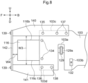
- the right upper reinforcement frame 140, the right lower reinforcement frame 141 and the electric motor 116 are disposed with a predetermined space W1 therebetween as seen in the side view, with the right upper reinforcement frame 140 and the right lower reinforcement frame 141 being positioned on the outer side.
- the left upper reinforcement frame 140, the left lower reinforcement frame 141 and the electric motor 116 are disposed with a predetermined space W2 therebetween as seen in the side view, with the left upper reinforcement frame 140 and the left lower reinforcement frame 141 being positioned on the outer side.
- the upper reinforcement frame 140 and the lower reinforcement frame 141 are disposed with a predetermined space W3 therebetween corresponding to the vertical width of the front portion of the machine body frame 103 as seen in the side view.
- harness 143 for supplying electric power of the battery 117 to the electric motor 116 or a cooling hose 144 for feeding/discharging cooling water to/from the electric motor 116 is to be disposed, such harness 143 or the cooling hose 144 will be disposed with effectively utilizing the space (space W1) between the right upper reinforcement frame 140, the right lower reinforcement frame 141 and the electric motor 116, the space between the left upper frame 140, the left lower frame 141 and the electric motor 116 (space W2) and the space (W3) between the upper reinforcement frame 140 and the lower reinforcement frame 141.
- an attachable and detachable lid member made of sheet metal or synthetic resin may be provided in the space (space W3) between the upper reinforcement frame 140 and the lower reinforcement frame 141.
- the lid member may be provided with an opening for allowing passage of the harness 143 or the cooling hose 144 therethrough.
- the front reinforcement frame 142 and the electric motor 116 are disposed with a predetermined space W4 therebetween as seem in the side view, with the front reinforcement frame 142 being positioned on the outer side.
- the front reinforcement frame 142 functions as a "bumper” for the front side of the electric grass cutting machine and functions also as a “protector” for protecting the front portion of the electric motor 116.
- An angle sensor (not shown) provided at the front portion of the electric motor 116 is protected by the front reinforcement frame 142.
- Respecting the space W1 between the right upper reinforcement frame 140 and the electric motor 116 and the space W1 between the right lower reinforcement frame 141 and the electric motor 116 may be set to a same value.
- one space W1 may be set to a large value and the other space W1 to a small value.
- Respecting the space W2 between the left upper reinforcement frame 140 and the electric motor 116, and the space W2 between the left lower reinforcement frame 141 and the electric motor 116, these may be set to a same value.
- one space W2 may be set to a large value and the other space W2 to a small value.
- the lower reinforcement frames 141 may be omitted and the right and left upper reinforcement frames 140 may be used as the "reinforcement frames".
- the upper reinforcement frames 140 may be connected to the vicinity of the vertical intermediate portions of the front portions of the machine body frames 103.
- the space W1 and the space W2 may be set to a same value or the space W1 may be set to a greater value than the space W2, or the space W2 may be set to a greater value than the space W1.
- the arrangement shown in Figs. 6 through 10 may be applied to the electric motor 109.
- a rotary cultivator for cultivating a field or an agent sprayer (not shown) for spraying an agent onto a field may be mounted as the "implement".
- a crawler type traveling device may be mounted.
- an electric work vehicle mounting an implement that does not require power it may be arranged such that the power of the above-described electric motor 109 is transmitted to the front wheels 101 and the rear wheels 102.
- right and left machine body frames 203 are disposed along the front/rear direction, and at front portions of the machine body frames 203, right and left front wheels 201 are supported and at rear portions of the machine body frames 203, right and left rear wheels 202 are supported.
- a driving section 204 is supported.
- a mower 205 is supported.
- a ROPS frame 206 is provided at rear portions of the machine body frames 203 and a grass collecting section 207 is supported to this ROPS frame 206.
- a transmission case 208 is connected; and to this transmission case 208, the right and left rear wheels 202 are supported.
- An electric motor 209 for traveling is disposed under a rear orientation and connected to a front portion of the transmission case 208. With power from the electric motor 209, the rear wheels 202 are driven.
- the ROPS frame 206 is connected to a rear portion of the transmission case 208.
- a driver's seat 210 and a steering wheel 211 for steering the front wheels 201 are provided in the driving section 204.
- the mower 205 is of a type in which three blades (not shown) rotatably driven about vertical axes are disposed side by side along the right/left direction.
- Front portions of right and left support links 212 are supported to be vertically pivotable about axes extending in the right/left direction of the machine body frames 203.
- the support links 212 extend rearwards and the mower 205 is connected to rear portions of the support links 212.
- FIG. 11-14 To front portions of the machine body frames 203, right and left support brackets 241 are connected. To/between the support brackets 241, an operational shaft 234 is rotatably supported. And, to a right end portion and a left end portion of the operational shaft 234, hook-like support members 234a are connected and an operational lever 234b is connected to the left support member 234a.
- support links 236 are connected and extend rearwards.
- a right portion and a left portion of the support shaft 235 are rotatably supported to support members 234a of the operational shafts 234 and the support links 236 extend rearwards to be connected to the mower 205.
- a coupling link 215 is connected between the operational arm 213 and a rear portion of the support link 214. In operation, as thee operational arm 213 is vertically pivoted by the lift cylinder 214, the mower 205 is lifted up/down.
- an electric motor 216 for driving the mower 205 is supported to front portions of the machine body frames 203 to be located forwardly of the front wheels 201 as seen in a side view.
- a battery 217 for supplying electric power to the electric motors 209, 216 is supported to an upper portion of the front portions of the machine body frames 203.
- a front support frame 218 in the form of a flat plate is connected to/between front portions of the right and left machine body frames 203.
- a support member 219 in the form of an angular tube is bolt-connected to protrude forwards from the support frame 218.
- a support frame 220 in the form of a flat plate is connected to/between front portions of the right and left machine body frames 203 and is disposed on the rear side of the support frame 218.
- a support frame 238 is connected to/between upper portions of the front end portions of the right and left machine body frames 203.
- a motor frame 228 formed by bending a flat plate is connected to the support frame 238 with bolts 239.
- a front transmission shaft 221 is disposed along the front/rear direction, wherein a front portion of this front transmission shaft 221 is rotatably supported by a bearing 223 inside the support member 219, and a rear portion of the front transmission shaft 221 is rotatably supported by a bearing 224 to the rear support frame 220.
- An input case 222 for transmitting power to the blades of the mower 205 is provided at the right/left center portion of the mower 205 and an input shaft 222a of the input case 222 extends forwards.
- a rear end portion of a rear transmission shaft 225 is connected via a universal joint 226 and a rear end portion of the rear transmission shaft 225 is connected to the input shaft 222a of the input case 222 via the universal joint 226.
- the motor frame 228 will be detached from the support frame 238.
- the operational lever 234b of the operational shaft 234 forwards, the support member 234a of the operational shaft 234 will be operated to the front side, and the support shaft 235 and the support link 236 will be detached from the support member 234a of the operational shaft 234.
- the electric motor 216 With the output shaft 216a of the electric motor 216 being oriented rearwards, will be inserted between the front portions of the right and left machine body frames 203 (between the right and left support brackets 241) and passed between the support frame 238 and the operational shaft 234.
- the output shaft 216a of the electric motor 216 will be inserted into the inside of the support member 219. Inside the support member 219, the output shaft 216a of the electric motor 216 will be connected to the portion of the front transmission shaft 221 which portion is supported to the support member 219 (bearing 223). The output shaft 216a of the electric motor 216 and the front transmission shaft 221 are connected via a spline arrangement.
- the portion of the electric motor 216 on the side of the output shaft 216a will be connected to the front end portion (flange portion 219a) of the support member 219, and the front support frame 218 and the portion of the electric motor 216 on the side of the output shaft 216a will be disposed with a space therebetween corresponding to the length of the support member 219.
- the motor frame 228 After establishment of connection between the portion of the electric motor 216 on the side of the output shaft 216a and the flange portion 219a of the support member 219, the motor frame 228 will be connected to the support frame 238 with bolts 239 and the motor frame 228 will be connected to the portion of the electric motor 216 opposite to the side of the output shaft 216a.
- the support shaft 235 and the support link 236 will be attached as shown in Figs. 11-14 .
- the electric motor 216 will be supported to the right and left machine body frames 203 via the support member 219 and the front support frame 218 and supported to the right and left machine body frames 203 via the motor frame 238 and the support frame 238.
- Power of the electric motor 216 is transmitted from the output shaft 216a of the electric motor 216 via the front transmission shaft 221 and the rear transmission shaft 225 to the input shaft 222a of the input case 222, whereby the blades of the mower 205 are rotatably driven.
- cut grass pieces cut by the mower 205 are fed through a duct 233 disposed laterally of the electric motor 209 and upwardly of the transmission case 208 to the grass collecting portion 207.
- an upper end portion 216c of the electric motor 216 is disposed at a position lower than an upper end portion 203b of the front portion of the machine body frame 203 as seen in the side view.
- a lower end portion 216d of the electric motor 216, as seen in the side view, is disposed at a position lower than a lower end portion 203c of the machine body frame 203.
- a rotational axis P1 of the front wheel 201 (the front wheel support portion 230), as seen in the side view, is disposed at a position lower than the lower end portion 203c of the front portion of the machine body frame 203, and the lower end portion 216d of the electric motor 216 is disposed at a position lower than the rotational axis P1 of the front wheel 201 (front wheel support portion 230), as seen in the side view.
- a front wheel support frame 229 to which the right and left front wheels 201 are supported to be steerable.
- Right and left front wheel support portions 230 supporting the front wheels 201 are supported to a right portion and a left portion of the front wheel support frame 229 to be steerable.
- a steering rod 231 operated along the front/rear direction by the steering wheel 211 is connected to a knuckle arm 230a of the left front wheel support portion 230 and to/between the right and left front wheel support portions 230, a tie rod 232 is connected.
- the tie rod 232 passes under the machine body frames 203 and under the universal joint 226 connecting the front transmission shaft 221 with the rear transmission shaft 225.
- the steering rod 231 is operated in the front/rear direction, whereby the front wheels 201 (front wheel support portions 230) are steered by the knuckle arm 230a of the left front wheel support portion 230 and the tie rod 232.
- a cylindrical boss portion 229a is connected to the right/left center portion of the front wheel support frame 229.
- a boss portion 229a of the front wheel support frame 229 is rotatably engaged and this front wheel support frame 229 is rollably supported to the front transmission shaft 221 to be capable of rolling.
- the right and left machine body frames 203 respectively define a cutout portion 203a which is opened downwards.
- the front wheel support frame 229 is fitted into the cutout portion 203a of the machine body frame 203 from the underside, rolling action of the front wheel support frame 229 is allowed.
- the positions at which the front wheel support frame 229 comes into abutment against an upper side portion of the cutout portion 303a of the machine body frame 203 are right and left limit positions of rolling of the front wheel support frame 229.
- the front support frame 218 is connected along the vertical direction to follow the cutout portion 203a of the machine body frame 203.
- the rear support frame 220 is connected along the vertical direction to follow the cutout portion 203a of the machine body frame 203.
- a rotary cultivator for cultivating a field or an agent sprayer (not shown) for spraying an agent onto a field may be mounted as the "implement".
Landscapes
- Engineering & Computer Science (AREA)
- Transportation (AREA)
- Mechanical Engineering (AREA)
- Chemical & Material Sciences (AREA)
- Combustion & Propulsion (AREA)
- Life Sciences & Earth Sciences (AREA)
- Sustainable Development (AREA)
- Sustainable Energy (AREA)
- Power Engineering (AREA)
- Arrangement Or Mounting Of Propulsion Units For Vehicles (AREA)
- Harvester Elements (AREA)
Description
- This invention relates to an electric work vehicle which employs an electric motor as a prime mover.
-
JP 2017-024710 A - With the above-described configuration in operation, power of the electric motor is transmitted via the transmission shaft to a speed changer device disposed inside the transmission case, and power from this speed changer device is transmitted to the rear wheels.
- At a rear portion of the transmission case, a PTO shaft is mounted to protrude rearwards. Power taken off the speed changer device is transmitted to this PTO shaft. Then, the power from the PTO shaft is transmitted to a rotary cultivator mounted at a rear portion of the electric tractor, thus driving the rotary cultivator.
- In
JP 2017-024710 A - Further, there exists an electric work vehicle designed based on an assumption of an implement being mounted between the front wheels and the rear wheels. There also exists an electric work vehicle assuming an implement being mounted at a front portion of a machine body frame.
- In such electric work vehicles, in case an implement is mounted between the front wheels and the rear wheels or an implement is mounted at a front portion of the machine body frame, there is a need for an arrangement that allows transmission of power of the electric motor to the implement appropriately.
- In the electric tractor disclosed in
JP 2017-024710 A - The electric motor is disposed between the right and left machine body frames. A rear portion of the electric motor is bolt-connected to the rear support frame, a front portion of the electric motor is bolt-connected to the front support frame, and a right portion and a left portion of the electric motor are placed in contact with the right and left frame body frames.
- In
JP 2017-024710 A - In this case, if the electric motor is supported to front portions of the machine body frames, this electric motor functions as a balance weight, thus being advantageous in adjustment of the front/rear balance of the electric work vehicle. Then, there is a need for an arrangement that allows an electric motor to achieve a function of a balance weight effectively in case the electric motor is supported to front portions of the machine body frames.
- In the electric tractor disclosed in
JP 2017-024710 A - With the above arrangement, when the electric motor is to be mounted to the machine body frames, it is necessary to align the position of the output shaft of the electric motor with the position of the transmission shaft with holding the transmission shaft temporarily so as not to change the position of this transmission shaft and to connect the output shaft of the electric motor to the transmission shaft. In this way, the electric motor needs to be mounted to the machine body. Therefore, there remains room for improvement in the respect of readiness of the work at the time of mounting of the electric motor. Namely, in an electric work vehicle, there is a need for improvement in the readiness of work at time of mounting of an electric motor to a machine body frame.
-
JP 2013 248918 claim 1. -
JP 2015 054620 -
US 2018/026244 discloses an electric work vehicle. -
- (1) In correspondence with First Related Art, there is proposed a non-claimed configuration as follows.
- An electric work vehicle comprising:
front wheels and rear wheels for traveling: - right and left machine body frames extending along a front/rear direction; and
- an electric motor, the electric motor having either one of a front output shaft protruding forwards or a rear output shaft protruding rearwards, the electric motor being supported to front portions of the machine body frames to be located forwardly of the front wheels as seen in a side view.
- With the above-described configuration, when an implement is mounted between the front wheels and the rear wheels, it is possible to arrange such that the power of the rear output shaft of the electric motor is transmitted via a transmission shaft, etc. to the implement. Whereas, when an implement is mounted to front portions of the machine body frames, it is possible to arrange such that the power of the front output shaft of the electric motor is transmitted via a transmission shaft, etc. to the implement.
- As described above, power of the electric motor can be transmitted to the implement, in appropriate correspondence with both the situation of the implement being mounted between the front wheels and the rear wheels and the situation of the implement being mounted to front portions of the machine body frames. As a result, the working efficiency of the electric work vehicle can be improved.
- An upper end portion of the electric motor may be disposed at a position lower than upper end portions of the front portions of the machine body frames, as seen in a side view.
- With the above-described configuration, as the electric motor is disposed at a low position, there is achieved an advantage with respect to lowering of the gravity center of the electric work vehicle.
- A lower end portion of the electric motor may be disposed at a position lower than lower end portions of the front portions of the machine body frames, as seen in a side view.
- A rotational axis of the front wheels may be disposed at a position lower than lower end portions of the front portions of the machine body frames, as seen in a side view; and
the lower end portion of the electric motor is disposed at a position lower than the rotational axis of the front wheels, as seen in a side view. - With either one of the above-described configurations, as the electric motor is disposed at an even lower position, there is achieved an advantage with respect to further lowering of the gravity center of the electric work vehicle.
- Axes of the front output shaft and the rear output shaft of the electric motor may be disposed at positions which are lower than the upper end portions of the front portions of the machine body frames and which also are higher than the rotational axis of the front wheels.
- With the above-described configuration, the motor can be disposed at a favorable position, with consideration to favorable balance between the respect of gravity center lowering and the respect of ensuring a minimal ground clearance for the electric work vehicle.
- (2) In correspondence with Second Related Art, there is proposed another non-claimed configuration as follows.
- An electric work vehicle comprising:
- right and left machine body frames extending along a front/rear direction;
- a support frame connected to/between front portions of the right and left machine body frames; and
- an electric motor for feeding power to at least one of a traveling device and an implement, the electric motor being connected to the support frame in such a manner as to protrude forwards from front end portions of the machine body frames as seen in a side view, and being supported to the right and left machine body frames via the support frame. With the above described configuration, in case the electric motor is supported to the front portions of the machine body frames, this electric motor is supported in such a manner as to protrude forwards from the front end portions of the machine body frame. Therefore, it is readily possible to secure a large amount of overhang of the electric motor, thus being advantageous in readiness of adjustment of the front/rear balance of the electric work vehicle being made possible. And, the electric motor can be disposed easily in such a manner as to protrude forwards from the front end portions of the machine body frames.
- Further, the support frame is connected to/between the front portions of the right and left machine body frames, the electric motor is connected to the support frame, and this electric motor is supported via the support frame to the right and left machine body frames. With this, the electric motor can be disposed easily without much trouble at a position between the right machine body frame and the left machine body frame and the electric motor can be readily disposed in such a manner as to protrude forwards from the front end portions of the machine body frames.
- An upper end portion of the electric motor may be disposed at a position lower than upper end portions of the front portions of the machine body frames, as seen in a side view.
- With the above-described configuration, as the electric motor is disposed at a position relatively low relative to the machine body frames, there is achieved an advantage with respect to lowering of the gravity center of the electric work vehicle.
- A lower end portion of the electric motor may bes disposed at a position higher than lower end portions of the front portions of the machine body frame as seen in a side view.
- With the above-described configuration, since the electric motor does not protrude downwards beyond the lower end portions of the front portions of the machine body frames, thus being advantageous in securing the minimal ground clearance for the electric work vehicle.
- According to a non-claimed configuration, the electric work vehicle further comprises:
- right and left reinforcement frames connected to the front portions of the right and left machine body frames and extending forwards;
- a front reinforcement frame connected to/between front portions of the right and left reinforcement frame and disposed forwardly of the electric motor;
- the right reinforcement frame and the electric motor being disposed with a predetermined space therebetween, with the right reinforcement frame being disposed on the outer side, as seen in a plan view; and
- the left reinforcement frame and the electric motor being disposed with a predetermined space therebetween, with the left reinforcement frame being disposed on the outer side, as seen in a plan view.
- With the above-described non-claimed configuration, the front reinforcement frame and the reinforcement frames are disposed to surround the electric motor and connected to the front portions of the right and left machine body frames. Thus, with the front reinforcement frame and the reinforcement frames, the front portions of the machine body frames and the vicinity of the support frame are reinforced, so that supporting strength of the electric motor can be achieved.
- Also, the reinforcement frames and the electric motor are spaced apart from each other in the right/left direction as seen in the plan view. This arrangement serves to facilitate flow of air between the reinforcement frames and the electric motor, thus being advantageous in the respect of promotion of heat discharge of the electric motor.
- Further, in laying out a harness or a cooling hose to be connected to the electric motor, the space between the reinforcement frames and the electric motor can be utilized, so that such harness and/or cooling hose can be disposed easily and smoothly.
- According to a non-claimed configuration, the electric work vehicle further comprises:
- right and left upper reinforcement frames connected to upper portions of the front portions of the right and left machine body frames and extending forwards;
- right and left lower reinforcement frames connected to lower portions of the front portions of the right and left machine body frames and extending forwards;
- a front reinforcement frame connected to/between front portions of the right and left upper reinforcement frames and front portions of the right and left lower reinforcement frames and disposed forwardly of the electric motor;
- the right upper reinforcement frame, the right lower reinforcement frame and the electric motor being disposed with a predetermined space therebetween, with the right upper reinforcement frame and the right lower reinforcement frame being disposed on the outer side, as seen in a plan view; and
- the left upper reinforcement frame, the left lower reinforcement frame and the electric motor being disposed with a predetermined space therebetween, with the left upper reinforcement frame and the left lower reinforcement frame being disposed on the outer side, as seen in a plan view.
- With the above-described non-claimed configuration, the front reinforcement frame, the upper reinforcement frames and the lower reinforcement frames are disposed to surround the electric motor and connected to the front portions of the right and left machine body frames. Thus, with the front reinforcement frame, the upper reinforcement frames and the lower reinforcement frames, the front portions of the machine body frames and the vicinity of the support frame are reinforced, so that supporting strength of the electric motor can be achieved.
- Also, the upper reinforcement frames, the lower reinforcement frames and the electric motor are spaced apart from each other in the right/left direction as seen in the plan view. This arrangement serves to facilitate flow of air between the upper reinforcement frames, the lower reinforcement frames and the electric motor, thus being advantageous in the respect of promotion of heat discharge of the electric motor.
- Further, in laying out a harness or a cooling hose to be connected to the electric motor, the space between the upper reinforcement frames, the lower reinforcement frames and the electric motor can be effectively utilized, so that such harness and/or cooling hose can be disposed easily and smoothly.
- The upper reinforcement frames and the lower reinforcement frames may be disposed with a predetermined space therebetween as seen in the side view.
- With the above-described configuration, the upper reinforcement frames and the lower reinforcement frames are spaced apart from each other in the vertical direction as seen in the side view. With this, air can flow easily between the upper reinforcement frames and the lower reinforcement frames, thus being advantageous in the respect of heat discharge of the electric motor.
- Further, in laying out a harness or a cooling hose to be connected to the electric motor, the space between the upper reinforcement frames and the lower reinforcement frames can be effectively utilized, so that such harness and/or cooling hose can be disposed easily and smoothly.
- A front portion of the electric motor may be connected to the front reinforcement frame.
- With the above-described configuration, in addition to the electric motor being supported via the support frame to the right and left machine body frames, the electric motor is supported also the front reinforcement frame and the reinforcement frames (the upper reinforcement frames, the lower reinforcement frames), improvement of the supporting strength of the electric motor can be achieved.
- With the configuration as defined in
claim 1, the front transmission shaft for transmitting power is supported to the right and left machine body frames via the support member and the front support frame. No change occurs in the position of the transmission shaft. Under this condition, by simply connecting the output shaft of the electric motor to the portion of the front transmission shaft supported to the support member, the output shaft of the electric motor can be connected to the front transmission shaft smoothly and easily. - Further, in addition to connecting the output shaft of the electric motor to the portion of the front transmission shaft supported to the support member, by connecting the portion of the electric motor on the side of the output shaft to the support member, the condition of the electric motor being supported to the right and left machine body frames via the support member and the front support frame can be obtained easily and smoothly.
- Moreover, the front support frame connected to/between the right and left machine body frames provides the function as a reinforcement member for the right and left machine body frames, in addition to the function of supporting the support member (the front transmission shaft).
- As described above, while the output shaft of the electric motor can be connected smoothly and easily to the front transmission shaft, the condition of the electric motor being supported to the right and left machine body frames can be obtained easily and smoothly, so that the readiness of operation in mounting the electric motor to the machine body frames can be improved. Moreover, the front support frame provides also the function as a reinforcement member for the right and left machine body frames, thus being advantageous with respect to improvement of the strength of the front portions of the right and left machine body frames.
- As mentioned in claim 1:
- the support member is connected to the front support frame to protrude forwards from the front support frame;
- a portion of the electric motor on the side of the output shaft is connected to a front end portion of the support member; and
- the front support frame and the portion of the electric motor on the side of the output shaft are disposed with a predetermined space therebetween.
- With the above-described configuration, when the portion of the electric motor on the side of the output shaft is connected to a front end portion of the support member, the front support frame and the portion of the electric motor on the side of the output shaft are spaced from each other. This arrangement serves to facilitate flow of air between the front support frame and the portion of the electric motor on the side of the output shaft, thus being advantageous for promotion of heat discharge from the electric motor.
- According to one preferred embodiment, the electric work vehicle further comprises a motor frame connected to/between a portion of the electric motor opposite to the output shaft and the right and left machine of improvement of the strength of the front portions of the right and left machine body frames.
- According to one preferred embodiment, the electric work vehicle further comprises:
- a front wheel support frame supporting right and left front wheels steerably;
- wherein the front wheel support frame is rollably supported to a portion of the front transmission shaft which portion is located between the front support frame and the rear support frame.
- With the above-described configuration, since the front wheel support frame supporting the right and left front wheels is rollably supported to the front transmission shaft, the front transmission shaft acts also as a support member for the front wheel support frame. So, this configuration is advantageous for configuration simplification.
- Moreover, since the front portion and the rear portion of the front transmission shaft are supported by the front support frame and the rear support frame, the supporting strength of the front transmission shaft is high.
- Further, since the front wheel support frame is rollably supported to the portion of the front transmission shaft located between the front support frame and the rear support frame, the supporting strength of the front wheel support frame is also high.
- According to one preferred embodiment:
- the respective machine body frame defines a cutout portion that allows rolling movement of the front wheel support frame with introduction of the front wheel support frame therein;
- at a portion of the machine body frame forwardly of the cutout portion, the front support frame is connected; and
- at a portion of the machine body frame rearwardly of the cutout portion, the rear support frame is connected.
- In the case of the arrangement of rollably supporting the front wheel support frame, in order to avoid interference between the front wheel support frame and the right and left machine body frames, a cutout portion that allows rolling movement of the front wheel support frame with introduction of the front wheel support frame therein may be provided in the right/left machine body frame.
- With the above-described configuration, since the front support frame and the rear support frame are supported respectively at the portions forwardly and rearwardly of the cutout portion of the right/left machine body frame, the vicinity portions of the cutout portions in the right and left machine body frames are reinforced by the front support frame and the rear support frame.
- With this, it is possible to suppress reduction in the strength of the vicinity portions of the cutout portions in the right and left machine body frames, thus being advantageous for improvement of the strength of the front portions of the right and left machine body frames.
-
-
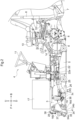
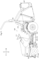
Fig. 1 is a left side view of an electric grass cutting machine (an example of an "electric work vehicle" in each embodiment) according to a first embodiment (same is true with subsequent drawings up toFig. 5 ), -
Fig. 2 is a left side view showing the inside of the electric grass cutting machine, -
Fig. 3 is an exploded perspective view showing vicinities of a front portion of a machine body frame and an electric motor, -
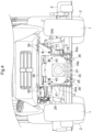
Fig. 4 is a front view showing vicinities of the front portion of the machine body frame and the electric motor, -
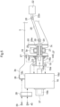
Fig. 5 is an exploded side view in vertical section showing vicinities of the front portion of the machine body frame and the electric motor, -
Fig. 6 is a left side view of an electric grass cutting machine according to a second embodiment (same is true with subsequent drawings up toFig. 10 ), -
Fig. 7 is a left side view showing the inside of the electric grass cutting machine, -
Fig. 8 is a left side view showing vicinities of a front portion of a machine body frame and an electric motor, -
Fig. 9 is a plan view showing vicinities of the front portion of the machine body frame and the electric motor, -
Fig. 10 is an exploded plan view in section showing vicinities of the front portion of the machine body frame and the electric motor, -
Fig. 11 is a left side view of an electric grass cutting machine according to a third embodiment (same is true with subsequent drawings up toFig. 15 ), -
Fig. 12 is a left side view showing the inside of the electric grass cutting machine, -
Fig. 13 is an exploded perspective view showing vicinities of a front portion of a machine body frame and an electric motor, -
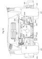
Fig. 14 is a front view showing vicinities of the front portion of the machine body frame and the electric motor, and -
Fig. 15 is an exploded side view in vertical section showing vicinities of the front portion of the machine body frame and the electric motor. - In the respective embodiment, a sign "F" denotes "front direction", a sign "B" denotes "rear direction", a sign "U" denotes an upper direction, a sign "D" denotes "lower direction", a sign "R" denotes "right direction" and a sign "L" denotes "left direction", respectively.
- As shown in
Fig. 1 andFig. 2 , right and left machine body frames 3 are disposed along the front/rear direction, and at front portions of the machine body frames 3, right and leftfront wheels 1 are supported; and at rear portions of the machine body frames 3, right and leftrear wheels 2 are supported. - Upwardly of the rear portions of the machine body frames 3, a
driving section 4 is supported. On the machine body frames 3 and between thefront wheels 1 and therear wheels 2, amower 5 is supported. At rear portions of the machine body frames 3, a rollover protection structure (ROPS)frame 6 is provided and a grass collecting section 7 is supported to thisROPS frame 6. - The above-described arrangements constitute a riding type electric grass cutting machine.
- As shown in
Fig. 1 andFig. 2 , to rear portions of the machine body frames 3, atransmission case 8 is connected; and to thistransmission case 8, the right and leftrear wheels 2 are supported. Anelectric motor 9 for traveling is disposed under a rear orientation and connected to a front portion of thetransmission case 8. With power from theelectric motor 9, therear wheels 2 are driven. - To a rear portion of the
transmission case 8, theROPS frame 6 is connected. A driver'sseat 10 and asteering wheel 11 for steering thefront wheels 1 are provided in thedriving section 4. - As shown in
Fig. 1 andFig. 2 , themower 5 is of a type in which three blades (not shown) rotatably driven about vertical axes are disposed side by side along the right/left direction. - Front portions of right and left support links 12 are supported to be vertically pivotable about axes extending in the right/left direction of the machine body frames 3. The support links 12 extend rearwards and the
mower 5 is connected to rear portions of the support links 12. - As shown in
Figs. 1 through 4 , right and leftsupport brackets 41 are connected to front portions of the machine body frames 3, and anoperational shaft 34 is rotatably supported to/between thesupport brackets 41. To a right end portion and a left end portion of theoperational shaft 34, hook-like support members 34a are connected, and anoperational lever 34b is connected to theleft support member 34a. - To a right portion and a left portion of a
support shaft 35 disposed along the right/left direction, support links 36 are connected and extend rearwards. The condition illustrated inFigs. 2 ,3 and4 is a condition in which the right portion and the left portion of thesupport shaft 35 are rotatably supported to thesupport members 34a of theoperational shafts 34 and the support links 36 extend rearwards to be connected to themower 5. - As shown in
Fig. 2 , vertically pivotable right and leftoperational arms 13 are provided andlift cylinders 14 are provided for pivotally operating theoperational arms 13. Acoupling link 15 is connected to/between the respectiveoperational arm 13 and the rear portion of therespective support link 12. In operation, as the respectiveoperational arm 13 is pivotally operated vertically by thelift cylinder 14, themower 5 is lifted up/down. - As shown in
Figs. 1 through 4 , anelectric motor 16 for driving themower 5 is supported to front portions of the machine body frames 3 to be located forwardly of thefront wheels 1 as seen in a side view. Abattery 17 for supplying electric power to theelectric motors - As shown in
Fig. 5 , theelectric motor 16 is provided with itsfront output shaft 16b protruding forwards and itsrear output shaft 16a protruding rearwards. The condition shown inFigs. 1 through 5 is a condition in which acover 37 is attached for covering thefront output shaft 16b of theelectric motor 16. - As shown in
Fig. 3 andFig. 5 , to/between front portions of the right and left machine body frames 3, asupport frame 18 in the form of a flat plate is connected. To aflange portion 18a of the front face portion of thesupport frame 18, asupport member 19 in the form of an angular tube is bolt-connected to protrude forwards from thesupport frame 18. Asupport frame 20 in the form of a flat plate is connected to/between front portions of the right and left machine body frames 3 and is disposed on the rear side of thesupport frame 18. - As shown in
Figs. 3 ,4 and5 , to/between upper portions of the front end portions of the right and left machine body frames 3, asupport frame 38 is connected. A connectingmember 28 formed by bending a flat plate is connected to thesupport frame 38 withbolts 39. - As shown in
Fig. 3 andFig. 5 , afront transmission shaft 21 is disposed along the front/rear direction, wherein a front portion of thisfront transmission shaft 21 is rotatably supported by a bearing 23 inside thesupport member 19, and a rear portion of thefront transmission shaft 21 is rotatably supported by a bearing 24 to thesupport frame 20. - An
input case 22 for transmitting power to the blades of themower 5 is provided at the right/left center portion of themower 5 and aninput shaft 22a of theinput case 22 extends forwards. To the rear end portion of thefront transmission shaft 21, a front end portion of arear transmission shaft 25 is connected via auniversal joint 26 and a rear end portion of therear transmission shaft 25 is connected to theinput shaft 22a of theinput case 22 via theuniversal joint 26. - As shown in
Figs. 3 ,4 and5 , the connectingmember 28 will be detached from thesupport frame 38. Then, by operating theoperational lever 34b of theoperational shaft 34 forwards, thesupport member 34a of theoperational shaft 34 is operated to the front side, whereby thesupport shaft 35 and thesupport link 36 will be detached from thesupport member 34a of theoperational shaft 34. - Under the above-described condition, with the
front output shaft 16b of theelectric motor 16 being oriented forwards and therear output shaft 16a of theelectric motor 16 being oriented rearwards, theelectric motor 16 will be passed between the front portions of the right and left machine body frames 3 (between the right and left support brackets 41), and passed between thesupport frame 28 and theoperational shaft 34. - Next, the
rear output shaft 16a of theelectric motor 16 will be inserted into thesupport member 19. Inside thesupport member 19, to the portion of thefront transmission shaft 21 supported to the support member 19 (bearing 23), therear output shaft 16a of theelectric motor 16 will be connected. Therear output shaft 16a of theelectric motor 16 and thefront output shaft 21 are connected via a spline arrangement. - When the
rear output shaft 16a of theelectric motor 16 has been inserted into thesupport member 19 and connected to thefront transmission shaft 21, the portion of theelectric motor 16 on the side of theoutput shaft 16a will be placed in contact with the flange portion 19a of thesupport member 19, so that the portion of theelectric motor 16 on the side of therear output shaft 16a and the flange portion 19a of thesupport member 19 will be connected to each other withbolts 27. - With the above, the portion of the
electric motor 16 on the side of therear output shaft 16a will be connected to the front end portion (flange portion 19a) of thesupport member 19; and thesupport frame 18 and the portion of theelectric motor 16 on the side of therear output shaft 16a will be disposed with a space therebetween that corresponds to the length of thesupport member 19. - After establishment of connection between the portion of the
electric motor 16 on the side of therear output shaft 16a and the flange portion 19a of thesupport member 19, the connectingmember 28 will be connected to thesupport frame 38 with thebolts 39 and the connectingmember 28 will be connected to an upper portion of the portion of theelectric motor 16 on the side of thefront output shaft 16b (cover 37) withbolts 40. Thesupport shaft 35 and the support links 36 will be attached as shown inFigs. 1 through 4 . - With the above-described configuration, the
electric motor 16 is supported to the right and left machine body frames 3 via thesupport member 19 and thesupport frame 18 and supported to the right and left machine body frames 3 via the connectingmember 28 and thesupport frame 38. - Power of the
electric motor 16 is transmitted to theinput shaft 22a of theinput case 22 from therear output shaft 16a of theelectric motor 16 via thefront transmission shaft 21 and therear transmission shaft 25, whereby the blades of themower 5 are rotatably driven. As shown inFig. 1 andFig. 2 , cut grass pieces cut by themower 5 will be conveyed and fed to the grass collecting portion 7 through aduct 33 disposed on the lateral side of theelectric motor 9 and the upper side of thetransmission case 8. - As shown in
Fig. 1 andFig. 2 , when theelectric motor 16 is supported to the machine body frames 3, thiselectric motor 16 is disposed forwardly of thefront wheels 1 as seen in the side view. - As shown in
Fig. 5 , anupper end portion 16c of theelectric motor 16 is disposed at a position lower than anupper end portion 3b of the front portion of themachine body frame 3 as seen in the side view. Whereas, alower end portion 16d of theelectric motor 16 is disposed at a position lower than thelower end portion 3c of the front portion of themachine body frame 3 as seen in the side view. - As shown in
Figs. 2 ,3 and5 , a rotational axis P1 of the front wheel 1 (the front wheel support portion 30) is disposed at a position lower than thelower end portion 3c of the front portion of themachine body frame 3 as seen in the side view; and thelower end portion 16d of theelectric motor 16 is disposed at a position lower than the rotational axis P1 of the front wheel 1 (front wheel support portion 30) as seen in the side view. - The condition illustrated in
Figs. 1 through 5 is a condition in which power of the electric motor 16 (rear output shaft 16a) is transmitted to themower 5 mounted between thefront wheels 1 and therear wheels 2. - In case the
mower 5 is not mounted between thefront wheels 1 and therear wheels 2, but thismower 5 is to be mounted to front portions of the machine body frames 3 or a different implement (not shown) is to be mounted to the front portions of the machine body frames 3, therear transmission shaft 25 and the universal joint 26 shown inFigs. 3 and5 will be detached and a cover (not shown) for covering the rear portion of thefront transmission shaft 21 will be attached. - The
cover 37 shown inFigs. 1-5 will be detached; instead, a transmission shaft (not shown) will be connected to/between an input shaft (not shown) of themower 5 mounted to the front portions of the machine body frames 3 or an input shaft (not shown) of the different implement and thefront output shaft 16b of theelectric motor 16. - As shown in
Figs. 3 ,4 and5 , there is provided a frontwheel support frame 29 to which the right and leftfront wheels 1 are supported to be steerable. Right and left frontwheel support portions 30 supporting thefront wheels 1 are supported to a right portion and a left portion of the frontwheel support frame 29 to be steerable. - A steering
rod 31 operated along the front/rear direction by thesteering wheel 11 is connected to aknuckle arm 30a of the left frontwheel support portion 30; and to/between the right and left frontwheel support portions 30, atie rod 32 is connected. In this case, thetie rod 32 passes under the machine body frames 3 and under the universal joint 26 connecting thefront transmission shaft 21 with therear transmission shaft 25. - With the above-described arrangement, when the
steering wheel 11 is operated, the steeringrod 31 is operated in the front/rear direction, whereby the front wheels 1 (front wheel support portions 30) are steered by theknuckle arm 30a of the left frontwheel support portion 30 and thetie rod 32. - As shown in
Fig. 3 andFig. 5 , acylindrical boss portion 29a is connected to the right/left center portion of the frontwheel support frame 29. Onto a portion of thefront transmission shaft 21 which portion is located between thesupport frame 18 and thesupport frame 20, aboss portion 29a of the frontwheel support frame 29 is rotatably engaged and this frontwheel support frame 29 is rollably supported to thefront transmission shaft 21 to be capable of rolling. - The right and left machine body frames 3 respectively defines a
cutout portion 3a which is opened downwards, and as the frontwheel support frame 29 is fitted into thecutout portion 3a of themachine body frame 3 from the underside, rolling action of the frontwheel support frame 29 is allowed. The positions at which the frontwheel support frame 29 comes into abutment against an upper side portion of thecutout portion 3a of themachine body frame 3 are right and left limit positions of rolling of the frontwheel support frame 29. - To a portion of the
machine body frame 3 adjacent the front side of thecutout portion 3a, thesupport frame 18 is connected along the vertical direction to follow thecutout portion 3a of themachine body frame 3. To a portion of themachine body frame 3 adjacent the rear side of thecutout portion 3a, thesupport frame 20 is connected along the vertical direction to follow thecutout portion 3a of themachine body frame 3. -
- (1) Instead of the
mower 5, a rotary cultivator (not shown) for cultivating a field or an agent sprayer (not shown) for spraying agent over a field can be mounted as the implement. - (2) The
electric motor 16 may incorporate a speed reduction mechanism (not shown), so that the power of theelectric motor 16 may be reduced through such speed reduction mechanism and outputted via therear output shaft 16a and thefront output shaft 16b of theelectric motor 16. - (3) The electric work vehicle is not limited to the electric grass cutting machine, but may be a riding type electric tractor or the like. These respects are same in the configurations of second and third embodiments to be described later, also.
- As shown in
Fig. 6 andFig. 7 , right and left machine body frames 103 are disposed along the front/rear direction, and at front portions of the machine body frames 103, right and left front wheels 101 (corresponding to a "traveling device") are supported, and at rear portions of the machine body frames 103, right and left rear wheels 102 (corresponding to a "traveling device") are supported. - Upwardly of the rear portions of the machine body frames 103, a
driving section 104 is supported. On the machine body frames 103 and between thefront wheels 101 and therear wheels 102, a mower 105 (corresponding to an "implement") is supported. At rear portions of the machine body frames 103, aROPS frame 106 is provided and agrass collecting section 107 is supported to thisROPS frame 106. - The above-described arrangements constitute a riding type electric grass cutting machine.
- As shown in
Fig. 6 andFig. 7 , to rear portions of the machine body frames 103, atransmission case 108 is connected and to thistransmission case 108, the right and leftrear wheels 102 are supported. Anelectric motor 109 for traveling is disposed under a rear orientation and connected to a front portion of thetransmission case 108. With power from theelectric motor 109, therear wheels 102 are driven. - To a rear portion of the
transmission case 108, theROPS frame 106 is connected. A driver'sseat 110 and asteering wheel 111 for steering thefront wheels 101 are provided in thedriving section 104. - As shown in
Fig. 6 andFig. 7 , themower 105 is of a type in which three blades (not shown) rotatably driven about vertical axes are disposed side by side along the right/left direction. - Front portions of right and left
support links 112 are supported to be vertically pivotable about axes extending in the right/left direction of the machine body frames 103. The support links 112 extend rearwards and themower 105 is connected to rear portions of the support links 112. - As will be described later (arrangements relating to front reinforcement frame connected to front portion of the machine body frames, and upper reinforcement frame and a lower reinforcement frame), to front portions of the machine body frames 103, right and left upper reinforcement frames 140 are connected; and right and left
support brackets 145 are connected to the upper reinforcement frames 140. Right and leftsupport brackets 145 are connected to the upper reinforcement frames 140. To lower portions of thesupport brackets 145, right and leftsupport links 146 are connected to be vertically pivotable and extend rearwards. And, to rear portions of the support links 146, themower 105 is connected. - There are provided right and left
operational arms 113 which are vertically pivotable. And, liftcylinders 114 for pivotally operating theoperational arms 113 are provided, and to/between theoperational arms 113 and the rear portions of the support links 112,coupling links 115 are connected. As theoperational arm 113 is vertically pivoted by thelift cylinder 114, themower 105 is lifted up/down. - As shown in
Figs. 8 ,9 and 10 , to/between front portions of the right and left machine body frames 103, asupport frame 118 in the form of a flat plate is connected, and to aflange portion 118a of the front face portion of thesupport frame 118, asupport member 119 in the form of an angular tube is bolt-connected to protrude forwards from thesupport frame 118. On the rear side of thesupport frame 118, asupport frame 120 in the form of a flat plate is connected to/between the front portions of the right and left machine body frames 103. - A
front transmission shaft 121 is disposed along the front/rear direction and a front portion of thisfront transmission shaft 121 is rotatably supported by abearing 123 inside thesupport member 119; and a rear portion of thefront transmission shaft 121 is rotatably supported by abearing 124 to thesupport frame 120. - An
input case 122 for transmitting power to the blades of themower 105 is provided at the right/left center portion of themower 105 and aninput shaft 122a of theinput case 122 extends forwards. To the rear end portion of thefront transmission shaft 121, a rear end portion of arear transmission shaft 125 is connected via auniversal joint 126 and a rear end portion of therear transmission shaft 125 is connected to theinput shaft 122a of theinput case 122 via theuniversal joint 126. - To/between front portions (front end portions) of the right and left machine body frames 103, a
support frame 128 in the form of a flat plate is connected withbolts support frame 128 is placed in contact with the front end portion of thesupport member 119, and anopening 128a is formed at the center portion of thesupport frame 128. - As shown in
Figs. 6 through 9 , right and left upper reinforcement frames 140 (corresponding to "reinforcement frame") are connected withbolts bolts 135, thesupport frame 128 and the upper reinforcement frames 140 are connected under temporarily mutually fastened states to the machine body frames 103. - Right and left lower reinforcement frames 141 (corresponding to "reinforcement frame") are connected with
bolts bolts 136, thesupport frame 128 and the lower reinforcement frames 141 are connected under temporarily mutually fastened states to the machine body frames 103. - A
front reinforcement frame 142 in the form of a flat plate is connected withbolts 139 to/between the front portions of the right and left upper reinforcement frames 140 and the front portions of the right and left lower reinforcement frames 141. As described previously (the supporting arrangement for the mower),support brackets 145 are connected to the upper reinforcement frames 140. - As shown in
Figs. 8 and9 , there is provided a frontwheel support frame 129 to which the right and leftfront wheels 101 are supported to be steerable. Right and left frontwheel support portions 130 supporting thefront wheels 101 are supported to a right portion and a left portion of the frontwheel support frame 129 to be steerable. - A steering
rod 131 operated along the front/rear direction by thesteering wheel 111 is connected to a knuckle arm 130a of the left frontwheel support portion 130 and to/between the right and left frontwheel support portions 130, atie rod 132 is connected. In this case, thetie rod 132 passes through anopening 103b of themachine body frame 103, and passes under theuniversal joint 126 connecting thefront transmission shaft 121 with therear transmission shaft 125. - With the above-described arrangement, when the
steering wheel 111 is operated, thesteering rod 131 is operated in the front/rear direction, whereby the front wheels 101 (front wheel support portions 130) are steered by the knuckle arm 130a of the left frontwheel support portion 130 and thetie rod 132. - As shown in
Fig. 8 ,9 and 10 , acylindrical boss portion 129a is connected to the right/left center portion of the frontwheel support frame 129. Onto a portion of thefront transmission shaft 121 which portion is located between thesupport frame 118 and thesupport frame 120, aboss portion 129a of the frontwheel support frame 129 is rotatably engaged; and this frontwheel support frame 129 is rollably supported to thefront transmission shaft 121 to be capable of rolling. - The right and left machine body frames 103 respectively defines a
cutout portion 103a which is opened downwards, and as the frontwheel support frame 129 is fitted into thecutout portion 3a of themachine body frame 103 from the underside, rolling action of the frontwheel support frame 129 is allowed. The positions at which the frontwheel support frame 129 comes into abutment against an upper side portion of thecutout portion 103a of themachine body frame 103 are right and left limit positions of rolling of the frontwheel support frame 129. - To a portion of the
machine body frame 103 adjacent the front side of thecutout portion 103a, thesupport frame 118 is connected along the vertical direction to follow thecutout portion 103a of themachine body frame 103. To a portion of themachine body frame 103 adjacent the rear side of thecutout portion 103a, thesupport frame 120 is connected along the vertical direction to follow thecutout portion 103a of themachine body frame 103. - As shown in
Figs. 6 and7 , anelectric motor 116 for driving themower 105 is provided. Abattery 117 for supplying electric power to theelectric motors - When the
electric motor 116 is to be supported to the machine body frames 103, as shown inFig. 10 , thefront reinforcement frame 142 and thebolts 139 will be detached from the upper reinforcement frames 140 and the lower reinforcement frames 141 and the support links 146 shown inFigs. 6 and7 will be detached. - Under the above-described condition, as shown in
Fig. 10 , theelectric motor 116 will be inserted between the right and left upper reinforcement frames 140 and between the right and left lower reinforcement frames 141, with theoutput shaft 116a of thiselectric motor 116 being oriented rearwards. - When the
output shaft 116a of theelectric motor 116 is inserted into thesupport member 119 through theopenings 128a of the support frames 128, inside thesupport member 119, theoutput shaft 116a of theelectric motor 116 will be connected to the portion of thefront transmission shaft 121 which portion is supported to the support member 119 (bearing 123). Theoutput shaft 116a of theelectric motor 116 and thefront transmission shaft 121 are connected via a spline arrangement. - As described above, when the
output shaft 116a of theelectric motor 116 has been inserted into thesupport member 119 and connected to thefront transmission shaft 121, the portion of theelectric motor 116 on the side of theoutput shaft 116a will come into contact with thesupport frame 128, so that the portion of theelectric motor 116 on the side of theoutput shaft 116a, thesupport frame 128 and theflange portion 119a of thesupport member 119 will be connected to each other withbolts 127. - With the above, the portion of the
electric motor 116 on the side of theoutput shaft 116a will be connected to the support member 128 (theflange portion 119a of the support member 119) and theelectric motor 116 will be supported to the right and left machine body frames 103 via thesupport frame 128, thesupport member 119 and thesupport frame 118. - Thereafter, when the
front reinforcement frame 142 is connected to the upper reinforcement frames 140 and the lower reinforcement frames 141 with thebolts 139, thefront reinforcement frame 142 is disposed forwardly of theelectric motor 116. Thesupport link 146, as shown inFig. 6 andFig. 7 , will be attached to/between thesupport bracket 145 and themower 105. - Power of the
electric motor 116 is transmitted to theinput shaft 122a of theinput case 122 from theoutput shaft 116a of theelectric motor 116, via thefront transmission shaft 121 and therear transmission shaft 125. As shown inFig. 6 andFig. 7 , cut grass pieces cut by themower 105 will be conveyed and fed to thegrass collecting portion 107 through aduct 133 disposed on the lateral side of theelectric motor 109 and the upper side of thetransmission case 108. - When the
electric motor 116 is to be detached, from the condition shown inFig. 8 andFig. 9 , thefront reinforcement frame 142 and thebolts 139 will be detached from the upper reinforcement frames 140 and the lower reinforcement frames 141 and thebolts 127 will be removed. Thesupport link 146 shown inFig. 6 andFig. 7 will be removed. - Thereafter, by withdrawing the
electric motor 116 to the front side, theoutput shaft 116a of theelectric motor 116 will be pulled out of thefront transmission shaft 121, and theelectric motor 116 will be withdrawn to the front side from between the right and left upper reinforcement frames 140 and between the right and left lower reinforcement frames 141. - As shown in
Fig. 8 andFig. 9 , when theelectric motor 116 is connected to thesupport frame 128, the position relations between thiselectric motor 116 and the respective portions are as described below. - The
electric motor 116 protrudes forwardly from the front end portions of the machine body frames 103 as seen in the side view and is positioned on the front side of thefront wheels 101. - An
upper end portion 116b of theelectric motor 116 is disposed at a position lower than theupper end portion 103c of the front portion of themachine body frame 103 as seen in the side view. Whereas, alower end portion 116c of theelectric motor 116 is disposed at a position higher than thelower end portion 103d of the front portion of themachine body frame 103 as seen in the side view. - The right
upper reinforcement frame 140, the rightlower reinforcement frame 141 and theelectric motor 116 are disposed with a predetermined space W1 therebetween as seen in the side view, with the rightupper reinforcement frame 140 and the rightlower reinforcement frame 141 being positioned on the outer side. - The left
upper reinforcement frame 140, the leftlower reinforcement frame 141 and theelectric motor 116 are disposed with a predetermined space W2 therebetween as seen in the side view, with the leftupper reinforcement frame 140 and the leftlower reinforcement frame 141 being positioned on the outer side. - The
upper reinforcement frame 140 and thelower reinforcement frame 141 are disposed with a predetermined space W3 therebetween corresponding to the vertical width of the front portion of themachine body frame 103 as seen in the side view. - In case a
harness 143 for supplying electric power of thebattery 117 to theelectric motor 116 or acooling hose 144 for feeding/discharging cooling water to/from theelectric motor 116 is to be disposed,such harness 143 or thecooling hose 144 will be disposed with effectively utilizing the space (space W1) between the rightupper reinforcement frame 140, the rightlower reinforcement frame 141 and theelectric motor 116, the space between the leftupper frame 140, the leftlower frame 141 and the electric motor 116 (space W2) and the space (W3) between theupper reinforcement frame 140 and thelower reinforcement frame 141. - In this case, in the space (space W3) between the
upper reinforcement frame 140 and thelower reinforcement frame 141, an attachable and detachable lid member (not shown) made of sheet metal or synthetic resin may be provided. In such arrangement, the lid member may be provided with an opening for allowing passage of theharness 143 or thecooling hose 144 therethrough. - The
front reinforcement frame 142 and theelectric motor 116 are disposed with a predetermined space W4 therebetween as seem in the side view, with thefront reinforcement frame 142 being positioned on the outer side. - The
front reinforcement frame 142 functions as a "bumper" for the front side of the electric grass cutting machine and functions also as a "protector" for protecting the front portion of theelectric motor 116. An angle sensor (not shown) provided at the front portion of theelectric motor 116 is protected by thefront reinforcement frame 142. -
- (1) Respecting the space W1 between the right
upper reinforcement frame 140, the rightlower reinforcement frame 141 and theelectric motor 116, and the space W2 between the leftupper reinforcement frame 140, the leftlower reinforcement frame 141 and theelectric motor 116 shown inFig. 9 , instead of setting the space W1 and the space W2 to a same value, it is also possible to set the space W1 to a greater value than the space W2, or vice versa, i.e., to set the space W2 to a greater value than the space W1. - Respecting the space W1 between the right
upper reinforcement frame 140 and theelectric motor 116 and the space W1 between the rightlower reinforcement frame 141 and theelectric motor 116, these may be set to a same value. Alternatively, one space W1 may be set to a large value and the other space W1 to a small value. - Respecting the space W2 between the left
upper reinforcement frame 140 and theelectric motor 116, and the space W2 between the leftlower reinforcement frame 141 and theelectric motor 116, these may be set to a same value. Alternatively, one space W2 may be set to a large value and the other space W2 to a small value. - (2) Of the upper reinforcement frames 140 and the lower reinforcement frames 141, e.g. the lower reinforcement frames 141 may be omitted and the right and left upper reinforcement frames 140 may be used as the "reinforcement frames". In this case, the upper reinforcement frames 140 may be connected to the vicinity of the vertical intermediate portions of the front portions of the machine body frames 103.
- In the above-described arrangement, respecting the space W1 between the right reinforcement frame and the
electric motor 116 and the space W2 between the left reinforcement frame and theelectric motor 116, the space W1 and the space W2 may be set to a same value or the space W1 may be set to a greater value than the space W2, or the space W2 may be set to a greater value than the space W1. - (3) It is possible to arrange such that the
electric motor 116 is supported to the right and left machine body frames 103 via thesupport frame 128 by connecting thefront reinforcement frame 142 to the front portion of theelectric motor 116 and also theelectric motor 116 is supported to the right and left machine body frames 103, via thefront reinforcement frame 142, the upper reinforcement frames 140 and the lower reinforcement frames 141. - (4) With omission of the upper reinforcement frames 140 and the lower reinforcement frames 141 as well as the
front reinforcement frame 142, it is possible to arrange such that theelectric motor 116 is supported to the right and left machine body frames 103 via the support frame 128 (thesupport member 119 and the support frame 118). - (5) With omission of the
electric motor 116, it is possible to arrange such that theelectric motor 109 is disposed at the front portions of the machine body frames 103 and power of thiselectric motor 109 is transmitted to thetransmission case 108 and this power transmitted to thetransmission case 108 is transmitted to thefront wheels 102 and the mower 105 (input case 122). - In the above-described arrangement, the arrangement shown in
Figs. 6 through 10 may be applied to theelectric motor 109. - Instead of the
mower 105, a rotary cultivator (not shown) for cultivating a field or an agent sprayer (not shown) for spraying an agent onto a field may be mounted as the "implement". Instead of thefront wheels 101 and therear wheels 102, a crawler type traveling device may be mounted. - In an electric work vehicle mounting an implement that does not require power, it may be arranged such that the power of the above-described
electric motor 109 is transmitted to thefront wheels 101 and therear wheels 102. - As shown in
Fig. 11 andFig. 12 , right and left machine body frames 203 are disposed along the front/rear direction, and at front portions of the machine body frames 203, right and leftfront wheels 201 are supported and at rear portions of the machine body frames 203, right and leftrear wheels 202 are supported. - Upwardly of the rear portions of the machine body frames 203, a
driving section 204 is supported. On the machine body frames 203 and between thefront wheels 201 and therear wheels 202, amower 205 is supported. At rear portions of the machine body frames 203, aROPS frame 206 is provided and agrass collecting section 207 is supported to thisROPS frame 206. - The above-described arrangements constitute a riding type electric grass cutting machine.
- As shown in
Fig. 11 andFig. 12 , to rear portions of the machine body frames 203, atransmission case 208 is connected; and to thistransmission case 208, the right and leftrear wheels 202 are supported. Anelectric motor 209 for traveling is disposed under a rear orientation and connected to a front portion of thetransmission case 208. With power from theelectric motor 209, therear wheels 202 are driven. - To a rear portion of the
transmission case 208, theROPS frame 206 is connected. A driver'sseat 210 and asteering wheel 211 for steering thefront wheels 201 are provided in thedriving section 204. - As shown in
Fig. 11 andFig. 12 , themower 205 is of a type in which three blades (not shown) rotatably driven about vertical axes are disposed side by side along the right/left direction. - Front portions of right and left
support links 212 are supported to be vertically pivotable about axes extending in the right/left direction of the machine body frames 203. The support links 212 extend rearwards and themower 205 is connected to rear portions of the support links 212. - As shown in
Figs. 11-14 , to front portions of the machine body frames 203, right and leftsupport brackets 241 are connected. To/between thesupport brackets 241, anoperational shaft 234 is rotatably supported. And, to a right end portion and a left end portion of theoperational shaft 234, hook-like support members 234a are connected and anoperational lever 234b is connected to theleft support member 234a. - To a right portion and a left portion of a
support shaft 235 disposed in the right/left direction, support links 236 are connected and extend rearwards. In the condition shown inFigs. 12 ,13 and14 , a right portion and a left portion of thesupport shaft 235 are rotatably supported to supportmembers 234a of theoperational shafts 234 and the support links 236 extend rearwards to be connected to themower 205. - As shown in
Fig. 12 , there are provided right and left vertically pivotableoperational arms 213 and liftcylinders 214 are provided for pivotally operating theoperational arms 213. Between theoperational arm 213 and a rear portion of thesupport link 214, acoupling link 215 is connected. In operation, as theeoperational arm 213 is vertically pivoted by thelift cylinder 214, themower 205 is lifted up/down. - As shown in
Figs. 11 through 14 , anelectric motor 216 for driving themower 205 is supported to front portions of the machine body frames 203 to be located forwardly of thefront wheels 201 as seen in a side view. Abattery 217 for supplying electric power to theelectric motors - As shown in
Fig. 13 andFig. 15 , to/between front portions of the right and left machine body frames 203, afront support frame 218 in the form of a flat plate is connected. To aflange portion 218a of the front face portion of thefront support frame 218, asupport member 219 in the form of an angular tube is bolt-connected to protrude forwards from thesupport frame 218. Asupport frame 220 in the form of a flat plate is connected to/between front portions of the right and left machine body frames 203 and is disposed on the rear side of thesupport frame 218. - As shown in
Figs. 13 ,14 and15 , to/between upper portions of the front end portions of the right and left machine body frames 203, asupport frame 238 is connected. Amotor frame 228 formed by bending a flat plate is connected to thesupport frame 238 withbolts 239. - As shown in
Fig. 13 andFig. 15 , afront transmission shaft 221 is disposed along the front/rear direction, wherein a front portion of thisfront transmission shaft 221 is rotatably supported by abearing 223 inside thesupport member 219, and a rear portion of thefront transmission shaft 221 is rotatably supported by abearing 224 to therear support frame 220. - An
input case 222 for transmitting power to the blades of themower 205 is provided at the right/left center portion of themower 205 and aninput shaft 222a of theinput case 222 extends forwards. To the rear end portion of thefront transmission shaft 221, a rear end portion of arear transmission shaft 225 is connected via auniversal joint 226 and a rear end portion of therear transmission shaft 225 is connected to theinput shaft 222a of theinput case 222 via theuniversal joint 226. - As shown in
Figs. 13 ,14 and15 , themotor frame 228 will be detached from thesupport frame 238. By operating theoperational lever 234b of theoperational shaft 234 forwards, thesupport member 234a of theoperational shaft 234 will be operated to the front side, and thesupport shaft 235 and thesupport link 236 will be detached from thesupport member 234a of theoperational shaft 234. - Under the above-described condition, the
electric motor 216, with theoutput shaft 216a of theelectric motor 216 being oriented rearwards, will be inserted between the front portions of the right and left machine body frames 203 (between the right and left support brackets 241) and passed between thesupport frame 238 and theoperational shaft 234. - Next, the
output shaft 216a of theelectric motor 216 will be inserted into the inside of thesupport member 219. Inside thesupport member 219, theoutput shaft 216a of theelectric motor 216 will be connected to the portion of thefront transmission shaft 221 which portion is supported to the support member 219 (bearing 223). Theoutput shaft 216a of theelectric motor 216 and thefront transmission shaft 221 are connected via a spline arrangement. - When the
output shaft 216a of theelectric motor 216 has been inserted into thesupport member 219 and connected to thefront transmission shaft 221, the portion of theelectric motor 216 on the side of theoutput shaft 216a will come into contact with theflange portion 219a of thesupport member 219, so that the portion of theelectric motor 216 on the side of theoutput shaft 216a and theflange portion 219a of thesupport member 219 will be connected to each other withbolts 227. - With the above, the portion of the
electric motor 216 on the side of theoutput shaft 216a will be connected to the front end portion (flange portion 219a) of thesupport member 219, and thefront support frame 218 and the portion of theelectric motor 216 on the side of theoutput shaft 216a will be disposed with a space therebetween corresponding to the length of thesupport member 219. - After establishment of connection between the portion of the
electric motor 216 on the side of theoutput shaft 216a and theflange portion 219a of thesupport member 219, themotor frame 228 will be connected to thesupport frame 238 withbolts 239 and themotor frame 228 will be connected to the portion of theelectric motor 216 opposite to the side of theoutput shaft 216a. Thesupport shaft 235 and thesupport link 236 will be attached as shown inFigs. 11-14 . - With the above-described arrangements, the
electric motor 216 will be supported to the right and left machine body frames 203 via thesupport member 219 and thefront support frame 218 and supported to the right and left machine body frames 203 via themotor frame 238 and thesupport frame 238. - Power of the
electric motor 216 is transmitted from theoutput shaft 216a of theelectric motor 216 via thefront transmission shaft 221 and therear transmission shaft 225 to theinput shaft 222a of theinput case 222, whereby the blades of themower 205 are rotatably driven. As shown inFig. 11 andFig. 12 , cut grass pieces cut by themower 205 are fed through aduct 233 disposed laterally of theelectric motor 209 and upwardly of thetransmission case 208 to thegrass collecting portion 207. - As shown in
Fig. 11 andFig. 12 , when theelectric motor 216 is supported to the machine body frames 203, thiselectric motor 216 is disposed forwardly of thefront wheels 201 as seen in the side view. - As shown in
Fig. 15 , anupper end portion 216c of theelectric motor 216 is disposed at a position lower than anupper end portion 203b of the front portion of themachine body frame 203 as seen in the side view. Alower end portion 216d of theelectric motor 216, as seen in the side view, is disposed at a position lower than alower end portion 203c of themachine body frame 203. - As shown in
Figs. 12 ,13 and15 , a rotational axis P1 of the front wheel 201 (the front wheel support portion 230), as seen in the side view, is disposed at a position lower than thelower end portion 203c of the front portion of themachine body frame 203, and thelower end portion 216d of theelectric motor 216 is disposed at a position lower than the rotational axis P1 of the front wheel 201 (front wheel support portion 230), as seen in the side view. - As shown in
Figs. 13 ,14 and15 , there is provided a frontwheel support frame 229 to which the right and leftfront wheels 201 are supported to be steerable. Right and left frontwheel support portions 230 supporting thefront wheels 201 are supported to a right portion and a left portion of the frontwheel support frame 229 to be steerable. - A steering
rod 231 operated along the front/rear direction by thesteering wheel 211 is connected to aknuckle arm 230a of the left frontwheel support portion 230 and to/between the right and left frontwheel support portions 230, atie rod 232 is connected. In this case, thetie rod 232 passes under the machine body frames 203 and under theuniversal joint 226 connecting thefront transmission shaft 221 with therear transmission shaft 225. - With the above-described arrangement, when the
steering wheel 211 is operated, thesteering rod 231 is operated in the front/rear direction, whereby the front wheels 201 (front wheel support portions 230) are steered by theknuckle arm 230a of the left frontwheel support portion 230 and thetie rod 232. - As shown in
Fig. 13 andFig. 15 , acylindrical boss portion 229a is connected to the right/left center portion of the frontwheel support frame 229. Onto a portion of thefront transmission shaft 221 which portion is located between thefront support frame 218 and therear support frame 220, aboss portion 229a of the frontwheel support frame 229 is rotatably engaged and this frontwheel support frame 229 is rollably supported to thefront transmission shaft 221 to be capable of rolling. - The right and left machine body frames 203 respectively define a
cutout portion 203a which is opened downwards. As the frontwheel support frame 229 is fitted into thecutout portion 203a of themachine body frame 203 from the underside, rolling action of the frontwheel support frame 229 is allowed. The positions at which the frontwheel support frame 229 comes into abutment against an upper side portion of the cutout portion 303a of themachine body frame 203 are right and left limit positions of rolling of the frontwheel support frame 229. - To a portion of the
machine body frame 203 adjacent the front side of thecutout portion 203a, thefront support frame 218 is connected along the vertical direction to follow thecutout portion 203a of themachine body frame 203. To a portion of themachine body frame 203 adjacent the rear side of thecutout portion 203a, therear support frame 220 is connected along the vertical direction to follow thecutout portion 203a of themachine body frame 203. -
- (1) With omission of the
electric motor 216, it is possible to arrange such that theelectric motor 209 is disposed at the front portions of the machine body frames 203 and power of thiselectric motor 209 is transmitted to thetransmission case 208 and this power transmitted to thetransmission case 208 is transmitted to therear wheels 202 and the mower 205 (input case 222). - In the above-described arrangement, the arrangement shown in
Figs. 13 ,14 and15 may be applied to theelectric motor 209. - (2) Instead of the
mower 205, a rotary cultivator (not shown) for cultivating a field or an agent sprayer (not shown) for spraying an agent onto a field may be mounted as the "implement".
Claims (5)
- An electric work vehicle comprising:right and left machine body frames (203) extending along a front/rear direction, with a forward traveling direction being taken as the front direction;a front support frame (218) connected to/between front portions of the right and left machine body frames (203);a support member (219) connected to the front support frame;a front transmission shaft (221) for transmitting power along the front/rear direction, the front transmission shaft being rotatably supported to the support member (219); andan electric motor (216) having a rearwardly oriented output shaft (216a),characterized in that the output shaft (216a) is supported to a portion of the front transmission shaft (221) which portion is supported to the support member (219);a portion of the electric motor (216) on the side of the output shaft is connected to the support member (219):the support member (219) is connected to the front support frame (218) to protrude forwards from the front support frame;a portion of the electric motor (216) on the side of the output shaft (216a) is connected to a front end portion of the support member; andthe front support frame (218) and the portion of the electric motor on the side of the output shaft are disposed with a predetermined space therebetween .
- The electric work vehicle of claim 1, further comprising a motor frame (228) connected to/between a portion of the electric motor (216) opposite to the output shaft (216a) and the right and left machine body frames (203).
- The electric work vehicle of claim 1 or 2, further comprising:a rear transmission shaft (225) connected via a universal joint (226) to a rear end portion of the front transmission shaft (221); anda rear support frame (220) disposed on the rear side of the front support frame (218) and connected to/between the right and left machine body frames;wherein a front portion of the front transmission shaft (221) is rotatably supported to the support member (219), and a rear portion of the front transmission shaft is rotatably supported to the rear support frame (220).
- The electric work vehicle of claim 3, further comprising:a front wheel support frame (229) supporting right and left front wheels (201) steerably;wherein the front wheel support frame (229) is rollably supported to a portion of the front transmission shaft (221) which portion is located between the front support frame and the rear support frame.
- The electric work vehicle of claim 4, wherein:the respective machine body frame (203) defines a cutout portion (203a) that allows rolling movement of the front wheel support frame (229) with introduction of the front wheel support frame therein;at a portion of the machine body frame (203) forwardly of the cutout portion (203a), the front support frame (218) is connected; andat a portion of the machine body frame (203) rearwardly of the cutout portion, the rear support frame (220) is connected.
Applications Claiming Priority (3)
| Application Number | Priority Date | Filing Date | Title |
|---|---|---|---|
| JP2018242571A JP7113741B2 (en) | 2018-12-26 | 2018-12-26 | electric work vehicle |
| JP2018245765A JP7106446B2 (en) | 2018-12-27 | 2018-12-27 | electric work vehicle |
| JP2018244946A JP7097806B2 (en) | 2018-12-27 | 2018-12-27 | Electric work vehicle |
Publications (2)
| Publication Number | Publication Date |
|---|---|
| EP3674121A1 EP3674121A1 (en) | 2020-07-01 |
| EP3674121B1 true EP3674121B1 (en) | 2024-04-03 |
Family
ID=68581466
Family Applications (1)
| Application Number | Title | Priority Date | Filing Date |
|---|---|---|---|
| EP19208953.0A Active EP3674121B1 (en) | 2018-12-26 | 2019-11-13 | Electric work vehicle |
Country Status (2)
| Country | Link |
|---|---|
| US (1) | US11148518B2 (en) |
| EP (1) | EP3674121B1 (en) |
Families Citing this family (4)
| Publication number | Priority date | Publication date | Assignee | Title |
|---|---|---|---|---|
| JP7390998B2 (en) * | 2020-09-16 | 2023-12-04 | 株式会社クボタ | grass cutting equipment |
| JP7362579B2 (en) * | 2020-09-16 | 2023-10-17 | 株式会社クボタ | electric work vehicle |
| JP7499737B2 (en) * | 2021-06-29 | 2024-06-14 | 株式会社クボタ | Electric work vehicle |
| JP7515451B2 (en) * | 2021-12-27 | 2024-07-12 | 株式会社クボタ | Electric work vehicle |
Family Cites Families (11)
| Publication number | Priority date | Publication date | Assignee | Title |
|---|---|---|---|---|
| US6101794A (en) * | 1998-06-03 | 2000-08-15 | Terracare Products Company, Inc. | Mower |
| US7017327B2 (en) * | 2003-12-10 | 2006-03-28 | Deere & Company | Hybrid electric tool carrier |
| EP1943894B1 (en) * | 2007-01-15 | 2010-05-19 | Kanzaki Kokyukoki Mfg. Co., Ltd. | Riding lawn mower |
| JP5974637B2 (en) | 2012-05-30 | 2016-08-23 | 井関農機株式会社 | Electric work vehicle |
| US9199526B2 (en) * | 2013-02-26 | 2015-12-01 | Jtekt Corporation | Vehicle and vehicle driving device |
| WO2014160041A1 (en) * | 2013-03-13 | 2014-10-02 | Husqvarna Ab | Riding lawn care vehicle auto idle system |
| JP6225352B2 (en) | 2013-09-12 | 2017-11-08 | 株式会社 神崎高級工機製作所 | Electric vehicle with cargo bed |
| JP6247163B2 (en) * | 2014-06-17 | 2017-12-13 | 株式会社クボタ | Riding mower |
| JP6172354B2 (en) | 2016-07-19 | 2017-08-02 | 井関農機株式会社 | Tractor |
| US11069936B2 (en) | 2016-07-22 | 2021-07-20 | Kubota Corporation | Electric work vehicle |
| US10980173B2 (en) * | 2017-09-13 | 2021-04-20 | Black & Decker Inc. | Riding mower with removeable battery module |
-
2019
- 2019-11-07 US US16/677,137 patent/US11148518B2/en active Active
- 2019-11-13 EP EP19208953.0A patent/EP3674121B1/en active Active
Also Published As
| Publication number | Publication date |
|---|---|
| US20200207199A1 (en) | 2020-07-02 |
| EP3674121A1 (en) | 2020-07-01 |
| US11148518B2 (en) | 2021-10-19 |
Similar Documents
| Publication | Publication Date | Title |
|---|---|---|
| EP3674121B1 (en) | Electric work vehicle | |
| US10112469B2 (en) | Electric work vehicle | |
| EP3295784B1 (en) | Mid-mount riding grass mower | |
| US7527298B2 (en) | Dust fender for riding type work vehicle | |
| US12139204B2 (en) | Work vehicle | |
| CN113473839B (en) | agricultural machinery | |
| US7300241B2 (en) | Front loader attachment construction and work vehicle having the attachment construction | |
| JP7113741B2 (en) | electric work vehicle | |
| JP7675643B2 (en) | electric work vehicle | |
| EP3476643B1 (en) | Work machine | |
| JP7097806B2 (en) | Electric work vehicle | |
| EP1317878B1 (en) | Lawn mower with grass collector | |
| US20040145172A1 (en) | Reinforcing frame construction for tractor having ROPS | |
| EP3461694B1 (en) | Work machine | |
| JP7106446B2 (en) | electric work vehicle | |
| US4304315A (en) | Tractor | |
| JP3908486B2 (en) | Frame-type tractor car body and complex work vehicle | |
| JP7753849B2 (en) | Work vehicles | |
| US11950525B2 (en) | Protective member and work vehicle | |
| EP3199427B1 (en) | Work vehicle | |
| JPS638488Y2 (en) | ||
| JPH0442965Y2 (en) | ||
| JP2007309267A (en) | Working vehicle | |
| JP2606613Y2 (en) | Power work vehicle | |
| JPS645445Y2 (en) |
Legal Events
| Date | Code | Title | Description |
|---|---|---|---|
| PUAI | Public reference made under article 153(3) epc to a published international application that has entered the european phase |
Free format text: ORIGINAL CODE: 0009012 |
|
| STAA | Information on the status of an ep patent application or granted ep patent |
Free format text: STATUS: REQUEST FOR EXAMINATION WAS MADE |
|
| 17P | Request for examination filed |
Effective date: 20191113 |
|
| AK | Designated contracting states |
Kind code of ref document: A1 Designated state(s): AL AT BE BG CH CY CZ DE DK EE ES FI FR GB GR HR HU IE IS IT LI LT LU LV MC MK MT NL NO PL PT RO RS SE SI SK SM TR |
|
| AX | Request for extension of the european patent |
Extension state: BA ME |
|
| STAA | Information on the status of an ep patent application or granted ep patent |
Free format text: STATUS: EXAMINATION IS IN PROGRESS |
|
| 17Q | First examination report despatched |
Effective date: 20210914 |
|
| GRAP | Despatch of communication of intention to grant a patent |
Free format text: ORIGINAL CODE: EPIDOSNIGR1 |
|
| STAA | Information on the status of an ep patent application or granted ep patent |
Free format text: STATUS: GRANT OF PATENT IS INTENDED |
|
| INTG | Intention to grant announced |
Effective date: 20231025 |
|
| GRAS | Grant fee paid |
Free format text: ORIGINAL CODE: EPIDOSNIGR3 |
|
| GRAA | (expected) grant |
Free format text: ORIGINAL CODE: 0009210 |
|
| STAA | Information on the status of an ep patent application or granted ep patent |
Free format text: STATUS: THE PATENT HAS BEEN GRANTED |
|
| AK | Designated contracting states |
Kind code of ref document: B1 Designated state(s): AL AT BE BG CH CY CZ DE DK EE ES FI FR GB GR HR HU IE IS IT LI LT LU LV MC MK MT NL NO PL PT RO RS SE SI SK SM TR |
|
| REG | Reference to a national code |
Ref country code: CH Ref legal event code: EP |
|
| REG | Reference to a national code |
Ref country code: IE Ref legal event code: FG4D |
|
| REG | Reference to a national code |
Ref country code: DE Ref legal event code: R096 Ref document number: 602019049358 Country of ref document: DE |
|
| REG | Reference to a national code |
Ref country code: LT Ref legal event code: MG9D |
|
| REG | Reference to a national code |
Ref country code: NL Ref legal event code: MP Effective date: 20240403 |
|
| REG | Reference to a national code |
Ref country code: AT Ref legal event code: MK05 Ref document number: 1671900 Country of ref document: AT Kind code of ref document: T Effective date: 20240403 |
|
| PG25 | Lapsed in a contracting state [announced via postgrant information from national office to epo] |
Ref country code: NL Free format text: LAPSE BECAUSE OF FAILURE TO SUBMIT A TRANSLATION OF THE DESCRIPTION OR TO PAY THE FEE WITHIN THE PRESCRIBED TIME-LIMIT Effective date: 20240403 |
|
| PG25 | Lapsed in a contracting state [announced via postgrant information from national office to epo] |
Ref country code: NL Free format text: LAPSE BECAUSE OF FAILURE TO SUBMIT A TRANSLATION OF THE DESCRIPTION OR TO PAY THE FEE WITHIN THE PRESCRIBED TIME-LIMIT Effective date: 20240403 |
|
| PG25 | Lapsed in a contracting state [announced via postgrant information from national office to epo] |
Ref country code: IS Free format text: LAPSE BECAUSE OF FAILURE TO SUBMIT A TRANSLATION OF THE DESCRIPTION OR TO PAY THE FEE WITHIN THE PRESCRIBED TIME-LIMIT Effective date: 20240803 |
|
| PG25 | Lapsed in a contracting state [announced via postgrant information from national office to epo] |
Ref country code: BG Free format text: LAPSE BECAUSE OF FAILURE TO SUBMIT A TRANSLATION OF THE DESCRIPTION OR TO PAY THE FEE WITHIN THE PRESCRIBED TIME-LIMIT Effective date: 20240403 |
|
| PG25 | Lapsed in a contracting state [announced via postgrant information from national office to epo] |
Ref country code: HR Free format text: LAPSE BECAUSE OF FAILURE TO SUBMIT A TRANSLATION OF THE DESCRIPTION OR TO PAY THE FEE WITHIN THE PRESCRIBED TIME-LIMIT Effective date: 20240403 Ref country code: FI Free format text: LAPSE BECAUSE OF FAILURE TO SUBMIT A TRANSLATION OF THE DESCRIPTION OR TO PAY THE FEE WITHIN THE PRESCRIBED TIME-LIMIT Effective date: 20240403 |
|
| PG25 | Lapsed in a contracting state [announced via postgrant information from national office to epo] |
Ref country code: GR Free format text: LAPSE BECAUSE OF FAILURE TO SUBMIT A TRANSLATION OF THE DESCRIPTION OR TO PAY THE FEE WITHIN THE PRESCRIBED TIME-LIMIT Effective date: 20240704 |
|
| PG25 | Lapsed in a contracting state [announced via postgrant information from national office to epo] |
Ref country code: PT Free format text: LAPSE BECAUSE OF FAILURE TO SUBMIT A TRANSLATION OF THE DESCRIPTION OR TO PAY THE FEE WITHIN THE PRESCRIBED TIME-LIMIT Effective date: 20240805 |
|
| PG25 | Lapsed in a contracting state [announced via postgrant information from national office to epo] |
Ref country code: ES Free format text: LAPSE BECAUSE OF FAILURE TO SUBMIT A TRANSLATION OF THE DESCRIPTION OR TO PAY THE FEE WITHIN THE PRESCRIBED TIME-LIMIT Effective date: 20240403 |
|
| PG25 | Lapsed in a contracting state [announced via postgrant information from national office to epo] |
Ref country code: CZ Free format text: LAPSE BECAUSE OF FAILURE TO SUBMIT A TRANSLATION OF THE DESCRIPTION OR TO PAY THE FEE WITHIN THE PRESCRIBED TIME-LIMIT Effective date: 20240403 |
|
| PG25 | Lapsed in a contracting state [announced via postgrant information from national office to epo] |
Ref country code: AT Free format text: LAPSE BECAUSE OF FAILURE TO SUBMIT A TRANSLATION OF THE DESCRIPTION OR TO PAY THE FEE WITHIN THE PRESCRIBED TIME-LIMIT Effective date: 20240403 |
|
| PG25 | Lapsed in a contracting state [announced via postgrant information from national office to epo] |
Ref country code: PL Free format text: LAPSE BECAUSE OF FAILURE TO SUBMIT A TRANSLATION OF THE DESCRIPTION OR TO PAY THE FEE WITHIN THE PRESCRIBED TIME-LIMIT Effective date: 20240403 |
|
| PG25 | Lapsed in a contracting state [announced via postgrant information from national office to epo] |
Ref country code: LV Free format text: LAPSE BECAUSE OF FAILURE TO SUBMIT A TRANSLATION OF THE DESCRIPTION OR TO PAY THE FEE WITHIN THE PRESCRIBED TIME-LIMIT Effective date: 20240403 |
|
| PG25 | Lapsed in a contracting state [announced via postgrant information from national office to epo] |
Ref country code: PT Free format text: LAPSE BECAUSE OF FAILURE TO SUBMIT A TRANSLATION OF THE DESCRIPTION OR TO PAY THE FEE WITHIN THE PRESCRIBED TIME-LIMIT Effective date: 20240805 Ref country code: PL Free format text: LAPSE BECAUSE OF FAILURE TO SUBMIT A TRANSLATION OF THE DESCRIPTION OR TO PAY THE FEE WITHIN THE PRESCRIBED TIME-LIMIT Effective date: 20240403 Ref country code: NO Free format text: LAPSE BECAUSE OF FAILURE TO SUBMIT A TRANSLATION OF THE DESCRIPTION OR TO PAY THE FEE WITHIN THE PRESCRIBED TIME-LIMIT Effective date: 20240703 Ref country code: LV Free format text: LAPSE BECAUSE OF FAILURE TO SUBMIT A TRANSLATION OF THE DESCRIPTION OR TO PAY THE FEE WITHIN THE PRESCRIBED TIME-LIMIT Effective date: 20240403 Ref country code: IS Free format text: LAPSE BECAUSE OF FAILURE TO SUBMIT A TRANSLATION OF THE DESCRIPTION OR TO PAY THE FEE WITHIN THE PRESCRIBED TIME-LIMIT Effective date: 20240803 Ref country code: HR Free format text: LAPSE BECAUSE OF FAILURE TO SUBMIT A TRANSLATION OF THE DESCRIPTION OR TO PAY THE FEE WITHIN THE PRESCRIBED TIME-LIMIT Effective date: 20240403 Ref country code: GR Free format text: LAPSE BECAUSE OF FAILURE TO SUBMIT A TRANSLATION OF THE DESCRIPTION OR TO PAY THE FEE WITHIN THE PRESCRIBED TIME-LIMIT Effective date: 20240704 Ref country code: FI Free format text: LAPSE BECAUSE OF FAILURE TO SUBMIT A TRANSLATION OF THE DESCRIPTION OR TO PAY THE FEE WITHIN THE PRESCRIBED TIME-LIMIT Effective date: 20240403 Ref country code: ES Free format text: LAPSE BECAUSE OF FAILURE TO SUBMIT A TRANSLATION OF THE DESCRIPTION OR TO PAY THE FEE WITHIN THE PRESCRIBED TIME-LIMIT Effective date: 20240403 Ref country code: CZ Free format text: LAPSE BECAUSE OF FAILURE TO SUBMIT A TRANSLATION OF THE DESCRIPTION OR TO PAY THE FEE WITHIN THE PRESCRIBED TIME-LIMIT Effective date: 20240403 Ref country code: BG Free format text: LAPSE BECAUSE OF FAILURE TO SUBMIT A TRANSLATION OF THE DESCRIPTION OR TO PAY THE FEE WITHIN THE PRESCRIBED TIME-LIMIT Effective date: 20240403 Ref country code: AT Free format text: LAPSE BECAUSE OF FAILURE TO SUBMIT A TRANSLATION OF THE DESCRIPTION OR TO PAY THE FEE WITHIN THE PRESCRIBED TIME-LIMIT Effective date: 20240403 Ref country code: RS Free format text: LAPSE BECAUSE OF FAILURE TO SUBMIT A TRANSLATION OF THE DESCRIPTION OR TO PAY THE FEE WITHIN THE PRESCRIBED TIME-LIMIT Effective date: 20240703 |
|
| REG | Reference to a national code |
Ref country code: DE Ref legal event code: R097 Ref document number: 602019049358 Country of ref document: DE |
|
| PG25 | Lapsed in a contracting state [announced via postgrant information from national office to epo] |
Ref country code: DK Free format text: LAPSE BECAUSE OF FAILURE TO SUBMIT A TRANSLATION OF THE DESCRIPTION OR TO PAY THE FEE WITHIN THE PRESCRIBED TIME-LIMIT Effective date: 20240403 |
|
| PG25 | Lapsed in a contracting state [announced via postgrant information from national office to epo] |
Ref country code: EE Free format text: LAPSE BECAUSE OF FAILURE TO SUBMIT A TRANSLATION OF THE DESCRIPTION OR TO PAY THE FEE WITHIN THE PRESCRIBED TIME-LIMIT Effective date: 20240403 |
|
| PG25 | Lapsed in a contracting state [announced via postgrant information from national office to epo] |
Ref country code: RO Free format text: LAPSE BECAUSE OF FAILURE TO SUBMIT A TRANSLATION OF THE DESCRIPTION OR TO PAY THE FEE WITHIN THE PRESCRIBED TIME-LIMIT Effective date: 20240403 Ref country code: SK Free format text: LAPSE BECAUSE OF FAILURE TO SUBMIT A TRANSLATION OF THE DESCRIPTION OR TO PAY THE FEE WITHIN THE PRESCRIBED TIME-LIMIT Effective date: 20240403 |
|
| PG25 | Lapsed in a contracting state [announced via postgrant information from national office to epo] |
Ref country code: SM Free format text: LAPSE BECAUSE OF FAILURE TO SUBMIT A TRANSLATION OF THE DESCRIPTION OR TO PAY THE FEE WITHIN THE PRESCRIBED TIME-LIMIT Effective date: 20240403 |
|
| PG25 | Lapsed in a contracting state [announced via postgrant information from national office to epo] |
Ref country code: SM Free format text: LAPSE BECAUSE OF FAILURE TO SUBMIT A TRANSLATION OF THE DESCRIPTION OR TO PAY THE FEE WITHIN THE PRESCRIBED TIME-LIMIT Effective date: 20240403 Ref country code: SK Free format text: LAPSE BECAUSE OF FAILURE TO SUBMIT A TRANSLATION OF THE DESCRIPTION OR TO PAY THE FEE WITHIN THE PRESCRIBED TIME-LIMIT Effective date: 20240403 Ref country code: RO Free format text: LAPSE BECAUSE OF FAILURE TO SUBMIT A TRANSLATION OF THE DESCRIPTION OR TO PAY THE FEE WITHIN THE PRESCRIBED TIME-LIMIT Effective date: 20240403 Ref country code: EE Free format text: LAPSE BECAUSE OF FAILURE TO SUBMIT A TRANSLATION OF THE DESCRIPTION OR TO PAY THE FEE WITHIN THE PRESCRIBED TIME-LIMIT Effective date: 20240403 Ref country code: DK Free format text: LAPSE BECAUSE OF FAILURE TO SUBMIT A TRANSLATION OF THE DESCRIPTION OR TO PAY THE FEE WITHIN THE PRESCRIBED TIME-LIMIT Effective date: 20240403 |
|
| PLBE | No opposition filed within time limit |
Free format text: ORIGINAL CODE: 0009261 |
|
| STAA | Information on the status of an ep patent application or granted ep patent |
Free format text: STATUS: NO OPPOSITION FILED WITHIN TIME LIMIT |
|
| 26N | No opposition filed |
Effective date: 20250106 |
|
| PG25 | Lapsed in a contracting state [announced via postgrant information from national office to epo] |
Ref country code: SI Free format text: LAPSE BECAUSE OF FAILURE TO SUBMIT A TRANSLATION OF THE DESCRIPTION OR TO PAY THE FEE WITHIN THE PRESCRIBED TIME-LIMIT Effective date: 20240403 |
|
| REG | Reference to a national code |
Ref country code: CH Ref legal event code: PL |
|
| PG25 | Lapsed in a contracting state [announced via postgrant information from national office to epo] |
Ref country code: MC Free format text: LAPSE BECAUSE OF FAILURE TO SUBMIT A TRANSLATION OF THE DESCRIPTION OR TO PAY THE FEE WITHIN THE PRESCRIBED TIME-LIMIT Effective date: 20240403 |
|
| PG25 | Lapsed in a contracting state [announced via postgrant information from national office to epo] |
Ref country code: LU Free format text: LAPSE BECAUSE OF NON-PAYMENT OF DUE FEES Effective date: 20241113 |
|
| REG | Reference to a national code |
Ref country code: CH Ref legal event code: PL |
|
| GBPC | Gb: european patent ceased through non-payment of renewal fee |
Effective date: 20241113 |
|
| PG25 | Lapsed in a contracting state [announced via postgrant information from national office to epo] |
Ref country code: CH Free format text: LAPSE BECAUSE OF NON-PAYMENT OF DUE FEES Effective date: 20241130 |
|
| REG | Reference to a national code |
Ref country code: BE Ref legal event code: MM Effective date: 20241130 |
|
| PG25 | Lapsed in a contracting state [announced via postgrant information from national office to epo] |
Ref country code: SE Free format text: LAPSE BECAUSE OF FAILURE TO SUBMIT A TRANSLATION OF THE DESCRIPTION OR TO PAY THE FEE WITHIN THE PRESCRIBED TIME-LIMIT Effective date: 20240403 |
|
| PG25 | Lapsed in a contracting state [announced via postgrant information from national office to epo] |
Ref country code: GB Free format text: LAPSE BECAUSE OF NON-PAYMENT OF DUE FEES Effective date: 20241113 Ref country code: BE Free format text: LAPSE BECAUSE OF NON-PAYMENT OF DUE FEES Effective date: 20241130 |
|
| PGFP | Annual fee paid to national office [announced via postgrant information from national office to epo] |
Ref country code: FR Payment date: 20250930 Year of fee payment: 7 |
|
| PG25 | Lapsed in a contracting state [announced via postgrant information from national office to epo] |
Ref country code: IE Free format text: LAPSE BECAUSE OF NON-PAYMENT OF DUE FEES Effective date: 20241113 |
|
| PGFP | Annual fee paid to national office [announced via postgrant information from national office to epo] |
Ref country code: DE Payment date: 20250930 Year of fee payment: 7 |
|
| PG25 | Lapsed in a contracting state [announced via postgrant information from national office to epo] |
Ref country code: IT Free format text: LAPSE BECAUSE OF FAILURE TO SUBMIT A TRANSLATION OF THE DESCRIPTION OR TO PAY THE FEE WITHIN THE PRESCRIBED TIME-LIMIT Effective date: 20240403 |
|
| PG25 | Lapsed in a contracting state [announced via postgrant information from national office to epo] |
Ref country code: HU Free format text: LAPSE BECAUSE OF FAILURE TO SUBMIT A TRANSLATION OF THE DESCRIPTION OR TO PAY THE FEE WITHIN THE PRESCRIBED TIME-LIMIT; INVALID AB INITIO Effective date: 20191113 |
|
| PG25 | Lapsed in a contracting state [announced via postgrant information from national office to epo] |
Ref country code: CY Free format text: LAPSE BECAUSE OF FAILURE TO SUBMIT A TRANSLATION OF THE DESCRIPTION OR TO PAY THE FEE WITHIN THE PRESCRIBED TIME-LIMIT; INVALID AB INITIO Effective date: 20191113 |