EP3673302B1 - System and method for object screening and handling - Google Patents
System and method for object screening and handling Download PDFInfo
- Publication number
- EP3673302B1 EP3673302B1 EP18779420.1A EP18779420A EP3673302B1 EP 3673302 B1 EP3673302 B1 EP 3673302B1 EP 18779420 A EP18779420 A EP 18779420A EP 3673302 B1 EP3673302 B1 EP 3673302B1
- Authority
- EP
- European Patent Office
- Prior art keywords
- screening
- hermetically sealed
- sealed environment
- vehicle
- data
- Prior art date
- Legal status (The legal status is an assumption and is not a legal conclusion. Google has not performed a legal analysis and makes no representation as to the accuracy of the status listed.)
- Active
Links
Images





Classifications
-
- B—PERFORMING OPERATIONS; TRANSPORTING
- B60—VEHICLES IN GENERAL
- B60P—VEHICLES ADAPTED FOR LOAD TRANSPORTATION OR TO TRANSPORT, TO CARRY, OR TO COMPRISE SPECIAL LOADS OR OBJECTS
- B60P3/00—Vehicles adapted to transport, to carry or to comprise special loads or objects
-
- B—PERFORMING OPERATIONS; TRANSPORTING
- B64—AIRCRAFT; AVIATION; COSMONAUTICS
- B64F—GROUND OR AIRCRAFT-CARRIER-DECK INSTALLATIONS SPECIALLY ADAPTED FOR USE IN CONNECTION WITH AIRCRAFT; DESIGNING, MANUFACTURING, ASSEMBLING, CLEANING, MAINTAINING OR REPAIRING AIRCRAFT, NOT OTHERWISE PROVIDED FOR; HANDLING, TRANSPORTING, TESTING OR INSPECTING AIRCRAFT COMPONENTS, NOT OTHERWISE PROVIDED FOR
- B64F1/00—Ground or aircraft-carrier-deck installations
- B64F1/36—Other airport installations
- B64F1/368—Arrangements or installations for routing, distributing or loading baggage
-
- G—PHYSICS
- G01—MEASURING; TESTING
- G01V—GEOPHYSICS; GRAVITATIONAL MEASUREMENTS; DETECTING MASSES OR OBJECTS; TAGS
- G01V5/00—Prospecting or detecting by the use of ionising radiation, e.g. of natural or induced radioactivity
- G01V5/20—Detecting prohibited goods, e.g. weapons, explosives, hazardous substances, contraband or smuggled objects
-
- G—PHYSICS
- G06—COMPUTING OR CALCULATING; COUNTING
- G06Q—INFORMATION AND COMMUNICATION TECHNOLOGY [ICT] SPECIALLY ADAPTED FOR ADMINISTRATIVE, COMMERCIAL, FINANCIAL, MANAGERIAL OR SUPERVISORY PURPOSES; SYSTEMS OR METHODS SPECIALLY ADAPTED FOR ADMINISTRATIVE, COMMERCIAL, FINANCIAL, MANAGERIAL OR SUPERVISORY PURPOSES, NOT OTHERWISE PROVIDED FOR
- G06Q10/00—Administration; Management
- G06Q10/08—Logistics, e.g. warehousing, loading or distribution; Inventory or stock management
Definitions
- This invention relates generally to systems and methods for object screening and handling, and more particularly to a travelling screening environment for security screening of objects en route to a transportation craft.
- Security is a vital aspect in commercial transportation infrastructures and conventional departure control systems typically require screening of objects, such as for presence of potentially dangerous and/or illegal contents or substances, prior to loading and/or embarking of the screened 'clean' objects onto the transportation craft, e.g. aircraft, ship, train, bus, etc.
- Various types of conventional baggage and passenger screening machines are known, such as Computed Tomography (CT) systems, explosives detection systems (EDS), X-ray systems, explosives trace detections (ETD), full-body scanners, metal detectors, etc.
- CT Computed Tomography
- EDS explosives detection systems
- ETD explosives trace detections
- full-body scanners e.g., full-body scanners, metal detectors, etc.
- object screening and handling systems are conventionally implemented at respective security check-points within a departure terminal.
- an automated data processing and control system 3 of a departure terminal receives in-transit notifications from vehicles 5 transporting passengers and/or baggage items to the departure terminal, or to transportation crafts departing from that terminal.
- Each vehicle 5 is configured with a primary screening unit 7 for obtaining information about the in-transit object(s) 9 from one or more measuring devices 12, such as sensors or scanners, provided in a hermetically sealed environment 11 of the vehicle 5.
- the sealed environment 11 may be the passenger cabin, the boot/trunk, or a separate sealed compartment of the cabin or boot/trunk.
- the sealed environment 11 may comprise, and/or be embodied as, a container adapted to be readily lifted and transported with the in-transit object 9a contained therein.
- sealed used throughout the embodiments is to be understood as meaning hermetically sealed when the vehicle 5 is in use, whereby the object 9 transported therein is insulated or protected from outside influences and substances, thereby ensuring that the measured screening parameters by the primary screen unit 7 are representative of the in-transit object 9 itself.
- FIGs 2A and 2B schematically illustrate one example of a conventional motor vehicle that is fitted or retrofitted with a plurality of measuring devices 12 located in the boot or trunk 61 (which may also be referred to as a luggage compartment or hold) of a motor vehicle 5.
- Figure 2A shows a schematic side view
- Figure 2B shows a corresponding rear view.
- the measuring devices 12 are arranged to be able to measure screening parameters of an object 9a that is located in the sealed environment, and operable to communicate measured data to the in-transit screening unit 7 of the vehicle's on-board system 17.
- One or more sealing elements 63 are provided in order to hermetically seal the internal space the boot or trunk 61 to form the sealed environment 11, when the lid 65 of the boot or trunk 61 is closed.
- the in-transit object(s) 9 are baggage items contained in the hermetically sealed environment 11, the baggage items associated with a passenger seated within the vehicle cabin and having an assigned travel ticket and itinerary associated with a respective commercial transportation craft.
- One or more of the measuring devices 12 implemented in the primary screening unit 7 may be of a type suitable to perform scanning of in-transit objects to the same specifications and requirements as known stationary scanners within airport terminals.
- the first measuring device 12a may include X-ray emitter and detector components to image the inside of the in-transit object 9a in a first plane.
- Such an X-ray device may be configured to follow a scanning route around the sealed environment to create a more detailed image of the object 9a.
- the shape of the environment may be further adapted to reduce or increase bounce back/reflection of the emitted rays.
- the first measuring device 12a may instead or additionally include an infrared imaging sensor, which may be configured to follow the same scan path as the X-ray device.
- the second measuring device 12b may also include X-ray emitter and detector components to image the inside of the in-transit object 9a in a second plane.
- the second measuring device 12b may instead or additionally include a particulate sensor for measuring the presence of dangerous and/or illegal substances on or in the in-transit object 9a.
- a measuring device 12b may be further adapted to establish an airflow, for example by means of a suction pump, and/or a fan (not shown) that may be located on the opposite side wall of the boot/trunk 61.
- the shape of boot/trunk space may also be adapted to control and direct the flow of air across the in-transit object 9a and towards the measuring device 12b.
- a measuring device 12 may be configured to include a vacuum device operable to create a partial vacuum, for example to the same pressure as an aircraft when in-flight, after the lid 65 is closed to seal the environment, and to direct the vacuum exhaust over a sensor of the measuring device 12. In this way, the measuring device 12 utilises the vacuum exhaust to achieve full scanning coverage of the in-transit object 9a.
- data received from the measuring device(s) 12 may be processed by the primary screening unit 7 and stored as in-transit screening data 13 in a memory 15 of the vehicle's on-board computing system 17.
- the screening data 13 may include information correlating the passenger, baggage item(s), an assigned identifier of the transportation craft, travel itinerary attributes, and/or the vehicle.
- the screening data 13 is communicated by a screening controller 19 of the vehicle on-board system 17 to the departure terminal system 3, via a data communication path 21.
- a departure control sub-system 23 of the departure terminal system 3 is configured with an in-transit data processing module 25 that receives the in-transit screening data 13 from the vehicle on-board system 17.
- the in-transit data processing module 25 includes a comparator to compare the measured screening parameters with predeterminable set values of corresponding security parameters, and a checking device to perform the in-transit security screening check, for example by determining that the security parameters are observed.
- the in-transit data processing module 25 may generate a security data token for transmission to and verification by, for example, the departure control sub-system 23 or a computing system of a third-party routing target.
- Object detectors 38 may be located upstream of each junction 35 and between each pair of consecutive motorized conveyor segments, transmitting position and movement event data for each detected baggage item, for example to the conveyor sub-system controller 39 and/or the departure control sub-system 23.
- the ingress point such as the check-in/drop-off counter, may be manned or automated, for example with an automated loading component 33-1 such as a robotic lifting arm, to transfer the baggage item 9a to a first conveyor route 31-1.
- the vehicle itself may include one or more automated arms for loading the baggage items onto a drop-off platform, trolley, container, etc.
- each baggage item is associated with a unique ID assigned by the departure control sub-system 23, for example in accordance with established IATA standards for baggage tags.
- the unique ID may be stored as data in a corresponding electronic bag tag 10a attached to the baggage item 9a.
- the electronic bag tag 10a may be of a type as described in WO2015/036738 .
- the unique ID may be encoded into a machine readable form that is printed on a conventional tag attached to the baggage item 9a.
- the departure terminal system 3 processes the received in-transit screening data 13 (or the security data token) to control object routing sub-systems of the airport terminal system 3, such as the baggage conveyor sub-system 29 that dynamically determines and sets a routing direction for a baggage item 9a upstream of a conveyor junction 35 on the basis of the associated in-transit screening data 13.
- a junction control unit 37a is assigned to each conveyor junction 35, under super-control of a baggage conveyor sub-system controller 39.
- the one or more object sensors 38 at each conveyor junction 35 detect a baggage item 9a upstream of the associated conveyor junction 35, and determine or identify the unique ID of the detected baggage item 9a.
- the junction sensors 38 may include a tag reader or communications interface for enabling one or more communications links to the electronic tag 10a to request and retrieve the stored unique ID.
- the communications links may comprise one or more of a short-range wireless link, such as Bluetooth ® , Bluetooth ® LE or Zigbee ® , and a wireless network data connection, for example using the GPRS, EDGE, 3G, 4G or 5G standards.
- the junction sensors 38 may include a camera or scanner for capturing the encoded unique ID printed on a conventional tag.
- the junction control unit 37a processes security attribute data of the subject baggage item 9a, received from the data processing module 27 of the departure control sub-system 23, and controls the associated conveyor junction 35 accordingly, for example to direct the subject baggage item 9a downstream to a screening route 31-2 for further screening by at least one secondary screening unit 41 of a secondary security screening sub-system 43, or to a loading route 31-3 for objects cleared for loading onto a specified aircraft, for example by an automated loading component 33-3 of a cargo loading sub-system 45.
- the secondary screening sub-system 43 may also include an automated loading component 33-2 to transfer baggage items 9a from the end of the screening route 31-2 to a screening area (not shown), and subsequent to screening by the secondary screening unit 41, to transfer the baggage items 9a back to the loading route 31-3.
- the various sub-systems of the departure terminal system 3 may be in electronic communication therebetween via a data network 47.
- the data network 47 may be any suitable data communication network or combination of networks, such as a wireless network, a local- or wide-area network including a corporate intranet or the Internet, using for example the TCP/IP protocol, or one or more of the cellular communication networks mentioned above.
- Figure 4 which comprises a first example in Figure 4A and a second example in Figure 4B , schematically illustrates a side view of respective examples of a vehicle 5 adapted or retrofitted with components of an automated loading component 33, according to another embodiment.
- the automated loading component 33 is provided to transfer baggage items 9a from the sealed environment 11 of the vehicle 5 to a determined conveying destination.
- exemplary embodiments illustrate the advantageous provision of a secured and trusted handover of a 'clean', i.e. security screened, baggage item 9a from one vehicle to another.
- Figure 4A illustrates an example of a vehicle 5 adapted with a first motorized conveyor segment 32-1 of the automated loading component 33, such as a roller, belt or band, on the base or floor of the sealed environment 11.
- the baggage item 9a rests on the conveyor segment 32-1 for screening by the primary screening unit 7 when the vehicle is in-transit to the departure terminal, using the one or more measuring devices 12 located in the sealed environment 11.
- access through an opening of the sealed environment 11 may be automatically controlled, for example by means of a motorised cover such as a door, lid, flap, gate, etc., when the on-board system 17 of the vehicle determines the vehicle is within a secure area of the departure terminal, and the baggage item 9a has passed the in-transit security screening checks.
- the cover may be further configured to seal and lock/unlock the opening based on a control device of the on-board system 17 that verifies the identity of a passenger associated with the baggage item.
- the system 17 may be configured to control access to the sealed environment 11 based on verification of identity data received via a data communication interface (not shown).
- identity data may identify a passenger associated with the baggage item 9a or a delegated authority.
- a corresponding second motorized conveyor segment 32-2 of the automated loading component 33 may be provided at each of the secondary screening sub-system 43 and the cargo loading sub-system 45, to automatically receive the screened baggage item 9a transferred from the first conveyor segment 32-1, and to move the baggage item 9a towards the determined conveying destination.
- the second motorized conveyor segment 32-2 may be provided on an autonomous runner or trolley 34-1 as shown in Figure 4A , to automatically move the received baggage item 9a resting thereon to the determined conveying destination.
- the aircraft hold may include one or more automated arms for handling the baggage items, the or each arm including a head for grasping an item of baggage from the trolley or platform, for loading the baggage item into the aircraft hold, for example onto a baggage conveyor on a floor of the aircraft hold.
- the vehicle 5 itself may include one or more automated arms for loading the baggage items into the aircraft hold or into a unit load device (ULD) destined for the aircraft hold.
- ULD unit load device
- FIG 3 is schematic block diagram illustrating elements of an object screening system 1b according to another exemplary embodiment, using corresponding reference numerals to those of Figure 1 where appropriate for corresponding elements.
- the in-transit object 9 is the passenger 9b seated within the hermetically sealed environment 11 of the vehicle cabin, and having an assigned travel ticket and itinerary associated with a respective commercial transportation craft.
- Each measuring device 12 may detect one or more measurable characteristics or attributes of the passenger 9b, such as size, weight, detected dangerous/illegal substances, temperature, moisture, biometric profile such as face, voice, finger print, etc.
- the departure terminal system 3 processes the received in-transit screening data 13 to control a vehicle routing sub-system 51 that dynamically determines and sets a routing direction for a vehicle transporting the passenger 9b that is upstream and on an approach route 57-1 of a routing junction 53, on the basis of the associated in-transit screening data 13.
- the vehicle routing junction 53 may include, for example, a motorised gate, switch or platform, to move or guide a vehicle along a conveyor route or path.
- a junction control unit 37b is assigned to each routing junction 53, for example under super-control by a controller 55 of the vehicle routing sub-system 51.
- the notification is received by the in-transit data processing module 25 of the departure control sub-system 23 and passed to the departure control sub-system controller 27.
- the departure control sub-system controller 27 retrieves stored departure status data 24 of the or each identified in-transit object 9 from the database 27, and assigns an initial security status to the or each identified in-transit object 9.
- the departure control sub-system controller 27 identifies and transmits security parameters associated with the identified in-transit object(s) 9, as a response back to the screening controller 19 of the on-board system 17.
- the screening controller 19 initiates primary screening of the identified in-transit object(s) 9 using the primary screening unit 7, at step S5-7.
- the passenger may interact with the on-board system 17 to initiate primary screening via a user interface of the screening controller 19.
- the screening controller 19 receives data from one or more measuring devices 12 provided in a hermetically sealed environment 11 of the vehicle 5, the data identifying one or more measurable characteristics or attributes of the or each in-transit object 9.
- the screening controller 19 may evaluate the data received from the one or more measuring devices 12, for example to compare the data against the corresponding security parameters received from the departure control sub-system 23.
- the screening controller 19 generates and transmits in-transmit screening data 13 to the departure terminal system 3, the screening data 13 including the data from one or more measuring devices 12 and/or the output of the evaluation.
- FIG. 6 illustrates an example computer system 600 in which the present invention, or portions thereof, can be implemented as computer-readable code.
- the method illustrated by the flowchart of Figure 5 can be implemented in one or more such systems 600.
- the on-board system, the departure terminal system architecture and/or the respective sub-systems of Figures 1 and 2 can also each be implemented in one or more such systems 600.
- Computer system 600 includes one or more processors, such as processor 604.
- Processor 604 can be a special purpose or a general-purpose processor.
- Processor 604 is connected to a communication infrastructure 606 (for example, a bus, or network). It will be appreciated that use of the terms “unit”, “module” and data processing “means” throughout the embodiments may form part of such a processor and implemented in software.
- secondary memory 610 may include other similar means for allowing computer programs or other instructions to be loaded into computer system 600.
- Such means may include, for example, a removable storage unit 622 and an interface 620.
- Examples of such means may include a program cartridge and cartridge interface (such as that found in video game devices), a removable memory chip (such as an EPROM, or PROM) and associated socket, and other removable storage units 622 and interfaces 620 which allow software and data to be transferred from the removable storage unit 622 to computer system 600.
- computer program medium “non-transitory computer readable medium,” and “computer usable medium” are used to generally refer to media such as removable storage unit 618, removable storage unit 622, and a hard disk installed in hard disk drive 612.
- Computer program medium, computer readable storage medium, and computer usable medium can also refer to memories, such as main memory 608 and secondary memory 610, which can be memory semiconductors (e.g. DRAMs, etc.). These computer program products are means for providing software to computer system 600.
- the invention is also directed to computer program products comprising software stored on any computer useable medium.
- Such software when executed in one or more data processing device, causes a data processing device(s) to operate as described herein.
- Embodiments of the invention employ any computer useable or readable medium, known now or in the future.
- Examples of computer useable mediums include, but are not limited to, primary storage devices (e.g., any type of random access memory), secondary storage devices (e.g., hard drives, floppy disks, CD ROMS, ZIP disks, tapes, magnetic storage devices, optical storage devices, MEMS, nano-technological storage device, etc.), and communication mediums (e.g., wired and wireless communications networks, local area networks, wide area networks, intranets, etc.).
- the junction control units are configured to determine a next destination for an approaching object, based on the associated in-transit screening data received from the primary screening unit.
- a routing controller may instead be provided, for example as a processing module of the conveyor/routing sub-system(s) or of the departure terminal system itself, to carry out the data processing as described above to determine a next destination for an object approaching a conveyor/routing junction.
- the routing controller may be configured to identify attributes assigned to the object, such as the associated transportation craft identifier, itinerary data and security status.
- the routing controller may then process the output of the primary security screening device and update the assigned security status data of the object accordingly, before generating routing data for the object in dependence upon the updated security status data of the object.
- the junction control unit assigned to the or each conveyor switch point may then be configured to receive the generated routing data from the routing controller for the object upstream of the conveyor switch point, and in response, to set a routing direction on the basis of the routing data, whereby the object is directed to a screening route for further screening by at least one secondary security screening device, or to a loading route for objects cleared for loading onto the assigned transportation craft.
Landscapes
- Physics & Mathematics (AREA)
- Engineering & Computer Science (AREA)
- General Physics & Mathematics (AREA)
- Life Sciences & Earth Sciences (AREA)
- Geophysics (AREA)
- General Life Sciences & Earth Sciences (AREA)
- High Energy & Nuclear Physics (AREA)
- Business, Economics & Management (AREA)
- Mechanical Engineering (AREA)
- Economics (AREA)
- Transportation (AREA)
- Public Health (AREA)
- Health & Medical Sciences (AREA)
- Human Resources & Organizations (AREA)
- Development Economics (AREA)
- Entrepreneurship & Innovation (AREA)
- Aviation & Aerospace Engineering (AREA)
- Marketing (AREA)
- Operations Research (AREA)
- Quality & Reliability (AREA)
- Strategic Management (AREA)
- Tourism & Hospitality (AREA)
- General Business, Economics & Management (AREA)
- Theoretical Computer Science (AREA)
- Analysing Materials By The Use Of Radiation (AREA)
Description
- This invention relates generally to systems and methods for object screening and handling, and more particularly to a travelling screening environment for security screening of objects en route to a transportation craft.
- Security is a vital aspect in commercial transportation infrastructures and conventional departure control systems typically require screening of objects, such as for presence of potentially dangerous and/or illegal contents or substances, prior to loading and/or embarking of the screened 'clean' objects onto the transportation craft, e.g. aircraft, ship, train, bus, etc. Various types of conventional baggage and passenger screening machines are known, such as Computed Tomography (CT) systems, explosives detection systems (EDS), X-ray systems, explosives trace detections (ETD), full-body scanners, metal detectors, etc. However, such object screening and handling systems are conventionally implemented at respective security check-points within a departure terminal. Providing and maintaining high levels of processing efficiencies in such conventional screening processes is difficult, as every unscreened 'dirty' object, such as items of baggage and passengers, must pass through the respective security check-points. The resulting bottlenecks and queues invariably lead to unsatisfactory overall passenger experience.
-
EP3112851 A1 discloses a system comprising: a vehicle comprising an environment, said environment comprising a conveyor device and one or more measuring devices, said conveyor device operable to displace a baggage item from a resting position into a moving position in a fully automatic manner by means of a motor; and a control module configured to control the conveyor device by: receiving, from the one or more measuring devices in the sealed environment of the vehicle, screening parameters of the baggage item; verifying the measured screening parameters against corresponding security parameters; and responsive to verification that the security parameters are observed, outputting a control signal to cause a displacing movement of the conveyor device. - What is desired is an alternative technical infrastructure for object screening and handling that alleviates inconveniences and inefficiencies of conventional systems.
- Aspects of the present invention are set out in the accompanying claims. According to a first aspect there is provided a system in accordance with
claim 1. According to a second aspect there is provided a storage medium in accordance withclaim 13. Preferred optional features are defined in the dependent claims. - There now follows, by way of example only, a detailed description of embodiments of the present invention, with references to the figures identified below.
-
Figure 1 is a schematic block diagram illustrating elements of an automated security inspection and routing system for in-transit objects according to an exemplary embodiment of the invention. -
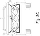
Figure 2 , which comprisesFigures 2A to 2C , schematically illustrates examples of a vehicle that is fitted or retrofitted with measuring devices of an in-transit screening unit according to an exemplary embodiment of the invention. -
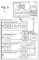
Figure 3 is a schematic block diagram illustrating elements of an automated security inspection and routing system for in-transit objects according to other exemplary embodiments of the invention. -
Figure 4 , which comprisesFigures 4A and 4B , schematically illustrates examples of a vehicle adapted or retrofitted with components of an automated loading component according to other exemplary embodiments of the invention. -
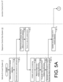
Figure 5 , which comprisesFigures 5A and5B , is a flow diagram illustrating the main processing steps performed by the systems ofFigures 1 and3 , according to another embodiment. -
Figure 6 is a diagram of an example of a computer system on which one or more of the functions of the embodiments may be implemented. -
Figure 1 is schematic block diagram illustrating elements of an object screening androuting system 1a according to an exemplary embodiment that relates to commercial travel. Aspects of the present embodiments are applicable to the automated screening of objects destined for any form of commercial transportation, such as airplane, ship, train and bus travel. More particularly, aspects of the present embodiments are described in the context of security screening of objects, such as a passenger and/or a baggage/luggage item, located in a vehicle that is transporting such in-transit objects towards a departure terminal, a conveying system of the departure terminal, or the commercial transportation craft departing from a departure terminal. It is appreciated that at least some of the elements are optional, at least for certain applications. - As shown in
Figure 1 , in this embodiment, an automated data processing andcontrol system 3 of a departure terminal receives in-transit notifications fromvehicles 5 transporting passengers and/or baggage items to the departure terminal, or to transportation crafts departing from that terminal. Eachvehicle 5 is configured with aprimary screening unit 7 for obtaining information about the in-transit object(s) 9 from one or moremeasuring devices 12, such as sensors or scanners, provided in a hermetically sealedenvironment 11 of thevehicle 5. The sealedenvironment 11 may be the passenger cabin, the boot/trunk, or a separate sealed compartment of the cabin or boot/trunk. Alternatively, thesealed environment 11 may comprise, and/or be embodied as, a container adapted to be readily lifted and transported with the in-transit object 9a contained therein. The term "sealed" used throughout the embodiments is to be understood as meaning hermetically sealed when thevehicle 5 is in use, whereby the object 9 transported therein is insulated or protected from outside influences and substances, thereby ensuring that the measured screening parameters by theprimary screen unit 7 are representative of the in-transit object 9 itself. -
Figures 2A and 2B schematically illustrate one example of a conventional motor vehicle that is fitted or retrofitted with a plurality ofmeasuring devices 12 located in the boot or trunk 61 (which may also be referred to as a luggage compartment or hold) of amotor vehicle 5.Figure 2A shows a schematic side view andFigure 2B shows a corresponding rear view. As shown, themeasuring devices 12 are arranged to be able to measure screening parameters of anobject 9a that is located in the sealed environment, and operable to communicate measured data to the in-transit screening unit 7 of the vehicle's on-board system 17. One ormore sealing elements 63 are provided in order to hermetically seal the internal space the boot ortrunk 61 to form thesealed environment 11, when thelid 65 of the boot ortrunk 61 is closed. In this embodiment, the in-transit object(s) 9 are baggage items contained in the hermetically sealedenvironment 11, the baggage items associated with a passenger seated within the vehicle cabin and having an assigned travel ticket and itinerary associated with a respective commercial transportation craft. - Each
measuring device 12 may measure one or more screening parameters, or measurable characteristics/attributes, of the in-transit object 9, such as size, weight, detected dangerous/illegal substances, temperature, moisture, biometric profile such as face, voice, finger print, etc. For example, the or eachmeasuring device 12 may be one or more of a pressure sensor, a camera, a microphone, a body scanner, CT/CAT/MRI/NMRI scanner, EDS, ETD, X-ray system and/or metal detector, particulate/substance detector, infrared scanner, sensors on a door of the vehicle, tamper seals, etc. Other sensors/scanners may be provided to detect measurable characteristics or attributes of ambient environment itself, such as air pressure, temperature, light level, sound, etc. which can be used to determine and/or verify that the sealed environment is not or has not been tampered with. One or more of themeasuring devices 12 implemented in theprimary screening unit 7 may be of a type suitable to perform scanning of in-transit objects to the same specifications and requirements as known stationary scanners within airport terminals. - As shown in the example of
Figures 2A and 2B , afirst measuring device 12a may be located centrally on a ceiling surface of the boot ortrunk 61 of thevehicle 5, substantially equidistant from the side walls of the boot ortrunk 61, to measure screening parameters of the object from a first screening direction, in this case from the top-down over a maximal coverage area. Asecond measuring device 12b may be located on a side wall of the boot ortrunk 61 to measure screening parameters of the object from a second screening direction, in this case transversely across the width of the sealed environment. - As an example configuration, the
first measuring device 12a may include X-ray emitter and detector components to image the inside of the in-transit object 9a in a first plane. Such an X-ray device may be configured to follow a scanning route around the sealed environment to create a more detailed image of theobject 9a. The shape of the environment may be further adapted to reduce or increase bounce back/reflection of the emitted rays. Thefirst measuring device 12a may instead or additionally include an infrared imaging sensor, which may be configured to follow the same scan path as the X-ray device. Thesecond measuring device 12b may also include X-ray emitter and detector components to image the inside of the in-transit object 9a in a second plane. Thesecond measuring device 12b may instead or additionally include a particulate sensor for measuring the presence of dangerous and/or illegal substances on or in the in-transit object 9a. Such ameasuring device 12b may be further adapted to establish an airflow, for example by means of a suction pump, and/or a fan (not shown) that may be located on the opposite side wall of the boot/trunk 61. The shape of boot/trunk space may also be adapted to control and direct the flow of air across the in-transit object 9a and towards themeasuring device 12b. - As another example configuration, a
measuring device 12 may be configured to include a vacuum device operable to create a partial vacuum, for example to the same pressure as an aircraft when in-flight, after thelid 65 is closed to seal the environment, and to direct the vacuum exhaust over a sensor of themeasuring device 12. In this way, themeasuring device 12 utilises the vacuum exhaust to achieve full scanning coverage of the in-transit object 9a. -
Figure 2C schematically illustrates another example of an alternative arrangement of measuring devices 12' that are fitted or retrofitted within the boot ortrunk 61 of amotor vehicle 5. As shown, a plurality of measuring devices 12', eight in the illustrated example, are located at respective positions of the internal surfaces of the boot ortrunk 61 of thevehicle 5, each having a respective effective scanning direction and range. Eachmeasuring device 12 is thereby arranged to measure screening parameters of theobject 9a from a respective screening direction, the combination of measuring devices 12' providing substantially full coverage of the internal area of the boot ortrunk 61. - Referring back to
Figure 1 , data received from the measuring device(s) 12 may be processed by theprimary screening unit 7 and stored as in-transit screening data 13 in amemory 15 of the vehicle's on-board computing system 17. Thescreening data 13 may include information correlating the passenger, baggage item(s), an assigned identifier of the transportation craft, travel itinerary attributes, and/or the vehicle. Thescreening data 13 is communicated by ascreening controller 19 of the vehicle on-board system 17 to thedeparture terminal system 3, via adata communication path 21. Thedata communication path 21 may be established over any suitable cellular communication network or combination of networks, such as Global System for Mobile Communications (GSM), General Packet Radio Service (GPRS), Code Division Multiple Access (CDMA), CDMA2000, Enhanced Data Rates for GSM Evolution (EDGE), Evolved High-Speed Packet Access (HSPTA+), Long Term Evolution (LTE), etc. - A
departure control sub-system 23 of thedeparture terminal system 3 is configured with an in-transitdata processing module 25 that receives the in-transit screening data 13 from the vehicle on-board system 17. In this exemplary embodiment, the in-transitdata processing module 25 includes a comparator to compare the measured screening parameters with predeterminable set values of corresponding security parameters, and a checking device to perform the in-transit security screening check, for example by determining that the security parameters are observed. Upon successful verification that the security parameters are observed, the in-transitdata processing module 25 may generate a security data token for transmission to and verification by, for example, thedeparture control sub-system 23 or a computing system of a third-party routing target. The token may comprises ID data identifying a verified status of a passenger or delegated authority that is associated with the 'clean'baggage item 9a. As an alternative, the data processing for the in-transit security screening check and security data token generation may be performed by thescreening controller 19 of the vehicle on-board system 17. - The
departure control sub-system 23 may include distributed computing terminals at a respective plurality of check-in/drop-off counters in the departure terminal. The received in-transit screening data 13 (or a security data token) is passed to asub-system controller 27 of thedeparture control sub-system 23, which monitors and updates the departure (e.g. check-in) status of the passengers and identified baggage items, stored asdeparture status data 24 for example in one ormore databases 26. Thedatabase 26 may be a relational database; however, any other type of data organizational structure may be used. Thedeparture status data 24 may include a security status attribute assigned to each in-transit object 9, which may be generated by the departurecontrol sub-system controller 27 based on the received in-transit screening data 13, and for example predefined security risk or assurance profile data. One example of a system for generating and dynamically monitoring a risk/assurance profile is described in the applicant's earlier applicationWO2017/032854 . Thedeparture terminal system 3 also includes abaggage conveyor sub-system 29 having conveying and routing components used to transport abaggage item 9a from an ingress point, such as a baggage drop-off point or a check-in counter, on one of a plurality of conveyor routes 31 to a routing destination based on the basis of the associated in-transit screening data 13. As is known in the art, the conveying components typically include motorized conveyor segments, such as rollers, belts or bands, andjunctions 35, such as motorized gates or switches, for moving baggage items along a conveyor route or path.Object detectors 38 may be located upstream of eachjunction 35 and between each pair of consecutive motorized conveyor segments, transmitting position and movement event data for each detected baggage item, for example to theconveyor sub-system controller 39 and/or thedeparture control sub-system 23. The ingress point, such as the check-in/drop-off counter, may be manned or automated, for example with an automated loading component 33-1 such as a robotic lifting arm, to transfer thebaggage item 9a to a first conveyor route 31-1. Alternatively, the vehicle itself may include one or more automated arms for loading the baggage items onto a drop-off platform, trolley, container, etc. - In this embodiment, each baggage item is associated with a unique ID assigned by the
departure control sub-system 23, for example in accordance with established IATA standards for baggage tags. The unique ID may be stored as data in a correspondingelectronic bag tag 10a attached to thebaggage item 9a. Theelectronic bag tag 10a may be of a type as described inWO2015/036738 . Alternatively, the unique ID may be encoded into a machine readable form that is printed on a conventional tag attached to thebaggage item 9a. - The
departure terminal system 3 processes the received in-transit screening data 13 (or the security data token) to control object routing sub-systems of theairport terminal system 3, such as thebaggage conveyor sub-system 29 that dynamically determines and sets a routing direction for abaggage item 9a upstream of aconveyor junction 35 on the basis of the associated in-transit screening data 13. In this exemplary embodiment, ajunction control unit 37a is assigned to eachconveyor junction 35, under super-control of a baggageconveyor sub-system controller 39. The one ormore object sensors 38 at eachconveyor junction 35 detect abaggage item 9a upstream of the associatedconveyor junction 35, and determine or identify the unique ID of the detectedbaggage item 9a. For example, thejunction sensors 38 may include a tag reader or communications interface for enabling one or more communications links to theelectronic tag 10a to request and retrieve the stored unique ID. The communications links may comprise one or more of a short-range wireless link, such as Bluetooth®, Bluetooth® LE or Zigbee®, and a wireless network data connection, for example using the GPRS, EDGE, 3G, 4G or 5G standards. Alternatively or additionally, thejunction sensors 38 may include a camera or scanner for capturing the encoded unique ID printed on a conventional tag. - The
junction control unit 37a processes security attribute data of thesubject baggage item 9a, received from thedata processing module 27 of thedeparture control sub-system 23, and controls the associatedconveyor junction 35 accordingly, for example to direct thesubject baggage item 9a downstream to a screening route 31-2 for further screening by at least onesecondary screening unit 41 of a secondarysecurity screening sub-system 43, or to a loading route 31-3 for objects cleared for loading onto a specified aircraft, for example by an automated loading component 33-3 of acargo loading sub-system 45. Thesecondary screening sub-system 43 may also include an automated loading component 33-2 to transferbaggage items 9a from the end of the screening route 31-2 to a screening area (not shown), and subsequent to screening by thesecondary screening unit 41, to transfer thebaggage items 9a back to the loading route 31-3. - The various sub-systems of the
departure terminal system 3 may be in electronic communication therebetween via adata network 47. Thedata network 47 may be any suitable data communication network or combination of networks, such as a wireless network, a local- or wide-area network including a corporate intranet or the Internet, using for example the TCP/IP protocol, or one or more of the cellular communication networks mentioned above. -
Figure 4 , which comprises a first example inFigure 4A and a second example inFigure 4B , schematically illustrates a side view of respective examples of avehicle 5 adapted or retrofitted with components of an automated loading component 33, according to another embodiment. As described above, the automated loading component 33 is provided to transferbaggage items 9a from the sealedenvironment 11 of thevehicle 5 to a determined conveying destination. These exemplary embodiments illustrate the advantageous provision of a secured and trusted handover of a 'clean', i.e. security screened,baggage item 9a from one vehicle to another. -
Figure 4A illustrates an example of avehicle 5 adapted with a first motorized conveyor segment 32-1 of the automated loading component 33, such as a roller, belt or band, on the base or floor of the sealedenvironment 11. Thebaggage item 9a rests on the conveyor segment 32-1 for screening by theprimary screening unit 7 when the vehicle is in-transit to the departure terminal, using the one ormore measuring devices 12 located in the sealedenvironment 11. In such an arrangement, access through an opening of the sealedenvironment 11 may be automatically controlled, for example by means of a motorised cover such as a door, lid, flap, gate, etc., when the on-board system 17 of the vehicle determines the vehicle is within a secure area of the departure terminal, and thebaggage item 9a has passed the in-transit security screening checks. The cover may be further configured to seal and lock/unlock the opening based on a control device of the on-board system 17 that verifies the identity of a passenger associated with the baggage item. Additionally or alternatively, thesystem 17 may be configured to control access to the sealedenvironment 11 based on verification of identity data received via a data communication interface (not shown). For example, the identity data may identify a passenger associated with thebaggage item 9a or a delegated authority. - A corresponding second motorized conveyor segment 32-2 of the automated loading component 33 may be provided at each of the
secondary screening sub-system 43 and thecargo loading sub-system 45, to automatically receive the screenedbaggage item 9a transferred from the first conveyor segment 32-1, and to move thebaggage item 9a towards the determined conveying destination. The second motorized conveyor segment 32-2 may be provided on an autonomous runner or trolley 34-1 as shown inFigure 4A , to automatically move the receivedbaggage item 9a resting thereon to the determined conveying destination. With such an arrangement, the on-board system 17 of the vehicle may include a control module for controlling the first conveyor segment 43-1 to allow thebaggage item 9a to be displaced from the resting position within the sealed environment into a moving position in a fully automatic manner, after receiving confirmation that the measured screening parameters meet with the corresponding security parameters. - Alternatively, an autonomous runner or trolley 34-2 of the automated loading component 33 may form a part of the
vehicle 5, provided within the sealedenvironment 11. The autonomous runner or trolley 34-2 may proceed to unload thebaggage item 9a from thevehicle 5, for example by moving onto a loading platform 46 or other conveying component, as shown inFigure 4B . - As yet a further alternative of an automated loading component 33, the aircraft hold may include one or more automated arms for handling the baggage items, the or each arm including a head for grasping an item of baggage from the trolley or platform, for loading the baggage item into the aircraft hold, for example onto a baggage conveyor on a floor of the aircraft hold. Alternatively, the
vehicle 5 itself may include one or more automated arms for loading the baggage items into the aircraft hold or into a unit load device (ULD) destined for the aircraft hold. -
Figure 3 is schematic block diagram illustrating elements of anobject screening system 1b according to another exemplary embodiment, using corresponding reference numerals to those ofFigure 1 where appropriate for corresponding elements. In this embodiment, the in-transit object 9 is thepassenger 9b seated within the hermetically sealedenvironment 11 of the vehicle cabin, and having an assigned travel ticket and itinerary associated with a respective commercial transportation craft. Each measuringdevice 12 may detect one or more measurable characteristics or attributes of thepassenger 9b, such as size, weight, detected dangerous/illegal substances, temperature, moisture, biometric profile such as face, voice, finger print, etc. For example, the measuringdevice 12 may be one or more of a pressure sensor, a camera, a microphone, a body scanner, CT scanner, EDS, ETD, X-ray system and/or metal detector, etc. Thescreening controller 19 may receive supplemental data from an RFID chip of a biometric passport via an RFID reader (not shown) to be correlated with data from the measuring device(s) 12. Thescreening data 13 is communicated by ascreening controller 19 of the vehicle on-board system 17 to thedeparture terminal system 3, via adata communication path 21. - In this embodiment, the
departure terminal system 3 processes the received in-transit screening data 13 to control avehicle routing sub-system 51 that dynamically determines and sets a routing direction for a vehicle transporting thepassenger 9b that is upstream and on an approach route 57-1 of arouting junction 53, on the basis of the associated in-transit screening data 13. Thevehicle routing junction 53 may include, for example, a motorised gate, switch or platform, to move or guide a vehicle along a conveyor route or path. Ajunction control unit 37b is assigned to eachrouting junction 53, for example under super-control by acontroller 55 of thevehicle routing sub-system 51. Thejunction control unit 37b processes security attribute data of thepassenger 9b, received from thedata processing module 27 of thedeparture control sub-system 23, and controls the associatedrouting junction 53 accordingly, for example to direct the vehicle downstream to a screening route 57-2 for further screening of the in-transit passenger 9b by at least onesecondary screening unit 41 of a secondarysecurity screening sub-system 43, or to different route that bypasses such further security screening, such as a boarding route 57-3 for passengers cleared for boarding onto the assigned aircraft, for example by an automated boarding sub-system 59. - It should be appreciated that the
system 1 may include other components, subcomponents, modules, and devices commonly found in a computing system/sub-system, such as a superordinate control system, which are not illustrated inFigures 1 and2 for clarity of the description. It is also appreciated that an existingvehicle 5 may be modified on a retrofit basis to implement the in-transit screening arrangement within a sealedenvironment 11 and to integrate the on-board system 17 of the vehicle into theobject screening system 1. The retrofitting kit may include sealing means to hermetically seal the cabin and/or hold environments of the vehicle. Thevehicle 5 may instead or additionally be a self-driving, autonomous vehicle that is configured to determine driving or routing directions based at least upon data received from thedeparture terminal system 3. As yet another example, thevehicle 5 may be an autonomous flying drone or an autonomous trolley, platform, or capsule used for transporting people, baggage items, goods, an automobile, etc. - A description has been given above of the components forming part of an
object screening system 1 of exemplary embodiments. The operation of these components will now be given with reference to the flow diagrams ofFigure 5 , for an example computer-implemented security inspection, routing and handling process for in-transit objects according to another embodiment. As shown, the process may begin at step S5-1 where thescreening controller 19 of the vehicle on-board system 17 detects the presence of one or more in-transit objects 9, such as baggage item(s) 9a and/or apassenger 9b. At step S5-3, thescreening controller 19 generates and transmits a notification to thedeparture terminal system 3 associated with the travel ticket and itinerary assigned to the passenger and/or baggage item(s), identifying the in-transit object(s) 9 and requesting security parameters associated with the object(s) 9. The on-board system 17 may prompt and receive ticket and/or itinerary information from the passenger in order to determine thedeparture terminal system 3 to receive the notification. Thescreening controller 19 may be further configured to verify the identity of a passenger associated with a baggage item. - At step S5-5, the notification is received by the in-transit
data processing module 25 of thedeparture control sub-system 23 and passed to the departurecontrol sub-system controller 27. The departurecontrol sub-system controller 27 retrieves storeddeparture status data 24 of the or each identified in-transit object 9 from thedatabase 27, and assigns an initial security status to the or each identified in-transit object 9. At step S5-6, the departurecontrol sub-system controller 27 identifies and transmits security parameters associated with the identified in-transit object(s) 9, as a response back to thescreening controller 19 of the on-board system 17. In response, thescreening controller 19 initiates primary screening of the identified in-transit object(s) 9 using theprimary screening unit 7, at step S5-7. Alternatively, the passenger may interact with the on-board system 17 to initiate primary screening via a user interface of thescreening controller 19. - At step S5-9, the
screening controller 19 receives data from one ormore measuring devices 12 provided in a hermetically sealedenvironment 11 of thevehicle 5, the data identifying one or more measurable characteristics or attributes of the or each in-transit object 9. At step S5-11, thescreening controller 19 may evaluate the data received from the one ormore measuring devices 12, for example to compare the data against the corresponding security parameters received from thedeparture control sub-system 23. At step S5-13, thescreening controller 19 generates and transmits in-transmitscreening data 13 to thedeparture terminal system 3, thescreening data 13 including the data from one ormore measuring devices 12 and/or the output of the evaluation. At step S5-15, thedeparture control sub-system 27 receives the in-transmitscreening data 13 via the in-transit processing module 25, and updates the security status of the or each in-transit object 9 in the associateddeparture status data 24 stored in thedatabase 26, to conclude the in-transit primary screening process. - The
vehicle 5 will subsequently approach the departure terminal, typically following completion of the in-transit primary screen process as described above. Accordingly, at step S5-17, thejunction control unit 37b of thevehicle routing sub-system 51 may detect that theupstream passenger 9b and/orvehicle 5 is approaching the associatedrouting junction 53, for example by means of the associated junction sensor(s) 39. In response, thejunction control unit 37b may retrieve the security status data of the identifiedpassenger 9b at step S5-19 from the associated storeddeparture status data 24, for example via the departurecontrol sub-system controller 27 and thedata network 47. At step S5-21, thejunction control unit 37b determines the next destination of thevehicle 5 transporting the in-transit passenger 9b. - At step S5-23, the
junction control unit 37b controls therouting junction 53 to route thevehicle 5, and thepassenger 9b, to the determined destination. The vehiclerouting sub-system controller 55 may be configured to monitor thevehicle 5 and/orpassenger 9b travelling along the determined route 57-2,57-3. At step S5-25, thejunction control unit 37b may generate and transmit a routing update notification for the in-transit passenger 9b, to thedeparture control sub-system 23. In response, the departurecontrol sub-system controller 27 may process the received notification identifying the in-transit passenger 9b, and update the security status data of the identifiedpassenger 9b, at step S5-27. At step 3-29, the departurecontrol sub-system controller 27 may subsequently receive further update notifications from the sub-systems associated with the determined destination, such as thesecondary screening sub-system 43 and boarding sub-system 57 following subsequent processing and/or handling of the identifiedpassenger 9b. At step S5-31, the departurecontrol sub-system controller 55 may update the security and departure status of the associatedpassenger 9b based on the received further update notifications. - It is appreciated that steps S5-17 to S5-31 may be carried out instead or additionally in relation to an in-
transit baggage item 9a approaching aconveyor junction 35 of thebaggage conveyor sub-system 29, whereby a routing determination is made by the associatedjunction control unit 37a based on the received in-transit screening data 13 associated with thebaggage item 9a, for example to route thebaggage item 9a toward either thesecondary screening sub-system 43 or thecargo loading sub-system 45. - Various aspects of the present invention can be implemented by software, firmware, hardware, or a combination thereof.
FIG. 6 illustrates anexample computer system 600 in which the present invention, or portions thereof, can be implemented as computer-readable code. For example, the method illustrated by the flowchart ofFigure 5 can be implemented in one or moresuch systems 600. The on-board system, the departure terminal system architecture and/or the respective sub-systems ofFigures 1 and2 can also each be implemented in one or moresuch systems 600. After reading this description, it will become apparent to a person skilled in the relevant art how to implement the invention using other computer systems and/or computer architectures. -
Computer system 600 includes one or more processors, such asprocessor 604.Processor 604 can be a special purpose or a general-purpose processor.Processor 604 is connected to a communication infrastructure 606 (for example, a bus, or network). It will be appreciated that use of the terms "unit", "module" and data processing "means" throughout the embodiments may form part of such a processor and implemented in software. -
Computer system 600 also includes amain memory 608, preferably random access memory (RAM), and may also include asecondary memory 610.Secondary memory 610 may include, for example, ahard disk drive 612, aremovable storage drive 614, flash memory, a memory stick, and/or any similar non-volatile storage mechanism.Removable storage drive 614 may comprise a floppy disk drive, a magnetic tape drive, an optical disk drive, a flash memory, or the like. Theremovable storage drive 614 reads from and/or writes to aremovable storage unit 618 in a well-known manner.Removable storage unit 618 may comprise a floppy disk, magnetic tape, optical disk, etc. which is read by and written to byremovable storage drive 614. As will be appreciated by persons skilled in the relevant art(s),removable storage unit 618 includes a non-transitory computer usable storage medium having stored therein computer software and/or data. - In alternative implementations,
secondary memory 610 may include other similar means for allowing computer programs or other instructions to be loaded intocomputer system 600. Such means may include, for example, aremovable storage unit 622 and aninterface 620. Examples of such means may include a program cartridge and cartridge interface (such as that found in video game devices), a removable memory chip (such as an EPROM, or PROM) and associated socket, and otherremovable storage units 622 andinterfaces 620 which allow software and data to be transferred from theremovable storage unit 622 tocomputer system 600. -
Computer system 600 may also include acommunications interface 624. Communications interface 624 allows software and data to be transferred betweencomputer system 600 and external devices. Communications interface 624 may include a modem, a network interface (such as an Ethernet card), a communications port, a PCMCIA slot and card, or the like. -
Computer system 600 may additionally includecomputer display 630. According to an embodiment,computer display 630, in conjunction with display interface 602, can be used to display UI 115 on operator console 110. - In this document, the terms "computer program medium," "non-transitory computer readable medium," and "computer usable medium" are used to generally refer to media such as
removable storage unit 618,removable storage unit 622, and a hard disk installed inhard disk drive 612. Computer program medium, computer readable storage medium, and computer usable medium can also refer to memories, such asmain memory 608 andsecondary memory 610, which can be memory semiconductors (e.g. DRAMs, etc.). These computer program products are means for providing software tocomputer system 600. - Computer programs (also called computer control logic) are stored in
main memory 608 and/orsecondary memory 610. Computer programs may also be received viacommunications interface 624. Such computer programs, when executed, enablecomputer system 600 to implement the present invention as discussed herein. In particular, the computer programs, when executed, enableprocessor 604 to implement the processes of the present invention, such as the steps in the methods illustrated by flowchart 200 ofFIG. 2 and system architecture 100 ofFIG. 1 discussed above. Accordingly, such computer programs represent controllers of thecomputer system 600. Where the invention is implemented using software, the software may be stored in a computer program product and loaded intocomputer system 600 usingremovable storage drive 614,interface 620,hard drive 612, orcommunications interface 624. - The invention is also directed to computer program products comprising software stored on any computer useable medium. Such software, when executed in one or more data processing device, causes a data processing device(s) to operate as described herein. Embodiments of the invention employ any computer useable or readable medium, known now or in the future. Examples of computer useable mediums include, but are not limited to, primary storage devices (e.g., any type of random access memory), secondary storage devices (e.g., hard drives, floppy disks, CD ROMS, ZIP disks, tapes, magnetic storage devices, optical storage devices, MEMS, nano-technological storage device, etc.), and communication mediums (e.g., wired and wireless communications networks, local area networks, wide area networks, intranets, etc.).
- It will be understood that embodiments of the present invention are described herein by way of example only, and that various changes and modifications may be made without departing from the scope of the invention.
- For example, in the embodiments described above, the junction control units are configured to determine a next destination for an approaching object, based on the associated in-transit screening data received from the primary screening unit. As an alternative, a routing controller may instead be provided, for example as a processing module of the conveyor/routing sub-system(s) or of the departure terminal system itself, to carry out the data processing as described above to determine a next destination for an object approaching a conveyor/routing junction. In such an embodiment, the routing controller may be configured to identify attributes assigned to the object, such as the associated transportation craft identifier, itinerary data and security status. The routing controller may then process the output of the primary security screening device and update the assigned security status data of the object accordingly, before generating routing data for the object in dependence upon the updated security status data of the object. The junction control unit assigned to the or each conveyor switch point may then be configured to receive the generated routing data from the routing controller for the object upstream of the conveyor switch point, and in response, to set a routing direction on the basis of the routing data, whereby the object is directed to a screening route for further screening by at least one secondary security screening device, or to a loading route for objects cleared for loading onto the assigned transportation craft.
- Reference in this specification to "one embodiment" are not necessarily all referring to the same embodiment, nor are separate or alternative embodiments mutually exclusive of other embodiments. Yet further alternative embodiments may be envisaged, which nevertheless fall within the scope of the following claims.
Claims (14)
- A system (1) comprising:a vehicle (5) comprising a hermetically sealed environment, the hermetically sealed environment comprising a conveyor device (32, 34) and one or more measuring devices (12, 12', 12a, 12b);the conveyor device (32, 34) operable to displace a baggage item (9) from a resting position into a moving position in a fully automatic manner by means of a motor, wherein the hermetically sealed environment comprises a container adapted to be readily lifted and transported with the baggage item (9) contained therein; anda control module configured to control the conveyor device (32, 34) by:receiving, from said one or more measuring devices in the hermetically sealed environment of the vehicle (5), screening parameters of the baggage item (9);verifying the measured screening parameters against corresponding security parameters; andresponsive to verification that the security parameters are observed, outputting a control signal to cause a displacing movement of the baggage item by the conveyor device (32, 34).
- The system (1) of claim 1, wherein the control module is further configured to determine that the vehicle (5) is adjacent a loading platform or a second conveyor device (32, 34) before controlling the displacing movement of the conveyor device (32, 34).
- The system (1) of claim 2, wherein the control module is further configured to transmit said measured screening parameters to a baggage conveying system of the loading platform or another conveyor device.
- The system (1) of any preceding claim, further comprising a data token generator configured to generate, responsive to checking by a checking device that the security parameters are observed, a security data token for transmission to and verification by a remote system.
- The system (1) of any one of claims 1 to 4, wherein the hermetically sealed environment is a hold, boot or trunk of a motor vehicle (5), which is sealed when a lid is closed.
- The system (1) of claim 5, wherein the hermetically sealed environment is hermetically sealed to prevent introduction of particles to the environment.
- The system (1) of any one of claims 5 or 6, wherein at least one measuring device (12) is located centrally on a ceiling surface of the hermetically sealed environment.
- The system (1) of any one of claims 5 to 7, wherein a plurality of measuring devices (12) are positioned at respective locations within the hermetically sealed environment to provide substantially full coverage of the internal area of the hermetically sealed environment.
- The system (1) of claim 8, wherein each measuring device (12) has a respective effective scanning direction and range.
- The system (1) of any preceding claim, wherein at least one measuring device (12) comprises means for suction of air in the hermetically sealed environment, to measure for the presence of particulates in the air.
- The system (1) of any preceding claim, wherein at least one measuring device (12) comprises sensor means for measuring one or more of visible or invisible characteristics, temperature, light, sound, pressure, and presence of dangerous and/or illegal substances.
- The system (1) of any preceding claim, further comprising means for controlling access to the hermetically sealed environment based on verification of identity data.
- A storage medium comprising machine readable instructions stored thereon for causing the system of claims 1 to 12 to execute the steps carried out by the control module.
- The system (1) of any one of claims 1 to 12, and further comprising means for transmitting screening data of an in-transit baggage item (9) to a remote server.
Applications Claiming Priority (2)
| Application Number | Priority Date | Filing Date | Title |
|---|---|---|---|
| GB1713462.8A GB2570097B (en) | 2017-08-22 | 2017-08-22 | System and method for object screening and handling |
| PCT/GB2018/052386 WO2019038543A1 (en) | 2017-08-22 | 2018-08-22 | System and method for object screening and handling |
Publications (2)
| Publication Number | Publication Date |
|---|---|
| EP3673302A1 EP3673302A1 (en) | 2020-07-01 |
| EP3673302B1 true EP3673302B1 (en) | 2024-07-10 |
Family
ID=59996798
Family Applications (1)
| Application Number | Title | Priority Date | Filing Date |
|---|---|---|---|
| EP18779420.1A Active EP3673302B1 (en) | 2017-08-22 | 2018-08-22 | System and method for object screening and handling |
Country Status (5)
| Country | Link |
|---|---|
| US (2) | US11585957B2 (en) |
| EP (1) | EP3673302B1 (en) |
| CN (1) | CN111279224A (en) |
| GB (1) | GB2570097B (en) |
| WO (1) | WO2019038543A1 (en) |
Families Citing this family (3)
| Publication number | Priority date | Publication date | Assignee | Title |
|---|---|---|---|---|
| GB2570097B (en) * | 2017-08-22 | 2021-02-10 | Int Consolidated Airlines Group S A | System and method for object screening and handling |
| CN111881247B (en) * | 2020-09-28 | 2020-12-22 | 民航成都物流技术有限公司 | Luggage path planning method, system and device and readable storage medium |
| CN114690261A (en) * | 2020-12-31 | 2022-07-01 | 同方威视技术股份有限公司 | Vehicle safety inspection system and safety inspection method |
Family Cites Families (36)
| Publication number | Priority date | Publication date | Assignee | Title |
|---|---|---|---|---|
| US3341986A (en) * | 1965-03-15 | 1967-09-19 | Brosig Hilburger | Levelling device |
| US5345809A (en) * | 1989-06-09 | 1994-09-13 | Research Corporation Technologies, Inc. | Explosive detection screening system |
| US5319547A (en) * | 1990-08-10 | 1994-06-07 | Vivid Technologies, Inc. | Device and method for inspection of baggage and other objects |
| US6738697B2 (en) | 1995-06-07 | 2004-05-18 | Automotive Technologies International Inc. | Telematics system for vehicle diagnostics |
| US5974111A (en) * | 1996-09-24 | 1999-10-26 | Vivid Technologies, Inc. | Identifying explosives or other contraband by employing transmitted or scattered X-rays |
| US6982643B2 (en) * | 2002-10-08 | 2006-01-03 | Freight Glove Technologies, Llc | Cargo security method and apparatus |
| US9015071B2 (en) * | 2000-09-08 | 2015-04-21 | Intelligent Technologies International, Inc. | Asset monitoring using the internet |
| US8786437B2 (en) * | 2000-09-08 | 2014-07-22 | Intelligent Technologies International, Inc. | Cargo monitoring method and arrangement |
| US7002472B2 (en) * | 2002-09-04 | 2006-02-21 | Northrop Grumman Corporation | Smart and secure container |
| US8451974B2 (en) * | 2003-04-25 | 2013-05-28 | Rapiscan Systems, Inc. | X-ray tomographic inspection system for the identification of specific target items |
| US6972693B2 (en) * | 2003-05-19 | 2005-12-06 | Brown Betty J | Vehicle security inspection system |
| US7605709B2 (en) * | 2004-02-09 | 2009-10-20 | Tolliver Charlie L | System, apparatus and method for screening personnel |
| US20050258231A1 (en) * | 2004-05-18 | 2005-11-24 | Keith Wiater | Cruise ship passenger and baggage processing system |
| US7312702B1 (en) * | 2005-02-22 | 2007-12-25 | Erudite Holding Llc | Expediting release procedure of cargo container at border crossing or at customs entry point by tracking and reporting threats while cargo container is in transit |
| GB2423687B (en) * | 2005-02-25 | 2010-04-28 | Rapiscan Security Products Ltd | X-ray security inspection machine |
| DE102005043490B4 (en) * | 2005-09-13 | 2013-08-29 | Kipp Gmbh & Co. Kg Cargo & Safety Systems | Motor vehicle with movable loading floor |
| WO2008060318A2 (en) * | 2006-03-23 | 2008-05-22 | Walters & Clune, Llc | Modular vehicle system and method |
| WO2011091070A2 (en) * | 2010-01-19 | 2011-07-28 | Rapiscan Systems, Inc. | Multi-view cargo scanner |
| US10228334B2 (en) * | 2010-02-16 | 2019-03-12 | Smiths Detection Group Limited | Adaptive modular cargo screening |
| MX2012009922A (en) * | 2010-02-26 | 2012-12-17 | Rapiscan Systems Inc | Integrated portable checkpoint system. |
| US8669861B1 (en) * | 2011-01-06 | 2014-03-11 | Globaltrak, Llc | Method for establishing a risk profile using RFID tags |
| US8827200B2 (en) * | 2011-09-16 | 2014-09-09 | Bogdan Radu | Flying vehicle |
| US10551851B2 (en) * | 2013-07-01 | 2020-02-04 | Steven Sounyoung Yu | Autonomous unmanned road vehicle for making deliveries |
| US9865066B2 (en) * | 2014-05-06 | 2018-01-09 | Astrophysics Inc. | Computed tomography system for cargo and transported containers |
| US20150378048A1 (en) * | 2014-06-27 | 2015-12-31 | American Science And Engineering, Inc. | Inspection of Baggage from within a Conveyance |
| CN105346975B (en) * | 2014-08-22 | 2017-12-22 | 清华大学 | Vehicle dragging system and vehicle inspection system |
| CN104360416A (en) | 2014-11-04 | 2015-02-18 | 同方威视技术股份有限公司 | Pull type security check channel |
| CN110286414A (en) * | 2014-12-17 | 2019-09-27 | 同方威视技术股份有限公司 | Trailer-type multi-view item inspection system and its application method |
| CN104464058B (en) * | 2014-12-17 | 2017-04-12 | 同方威视技术股份有限公司 | Item security check method and item security check system based on item identification tag |
| US20160189087A1 (en) * | 2014-12-30 | 2016-06-30 | Hand Held Products, Inc,. | Cargo Apportionment Techniques |
| CN105277577B (en) * | 2015-11-18 | 2019-02-19 | 清华大学 | Darkroom type security inspection equipment and method |
| CN206020299U (en) * | 2016-08-05 | 2017-03-15 | 上海工程技术大学 | A kind of energy-conservation subway rays safety detection apparatus |
| CN206224580U (en) * | 2016-08-26 | 2017-06-06 | 特斯联(北京)科技有限公司 | A kind of GPS Intelligent logistics monitoring system |
| CN206224582U (en) * | 2016-08-26 | 2017-06-06 | 特斯联(北京)科技有限公司 | A kind of Intelligent logistics management system based on RFID technique |
| CN206399376U (en) * | 2016-10-31 | 2017-08-11 | 紫光智云(江苏)物联网科技有限公司 | The Third-party Logistics of target item |
| GB2570097B (en) * | 2017-08-22 | 2021-02-10 | Int Consolidated Airlines Group S A | System and method for object screening and handling |
-
2017
- 2017-08-22 GB GB1713462.8A patent/GB2570097B/en active Active
-
2018
- 2018-08-22 WO PCT/GB2018/052386 patent/WO2019038543A1/en not_active Ceased
- 2018-08-22 US US16/640,979 patent/US11585957B2/en active Active
- 2018-08-22 CN CN201880055020.5A patent/CN111279224A/en active Pending
- 2018-08-22 EP EP18779420.1A patent/EP3673302B1/en active Active
-
2023
- 2023-02-10 US US18/167,698 patent/US12111442B2/en active Active
Also Published As
| Publication number | Publication date |
|---|---|
| GB2570097B (en) | 2021-02-10 |
| GB2570097A (en) | 2019-07-17 |
| US12111442B2 (en) | 2024-10-08 |
| US20230194745A1 (en) | 2023-06-22 |
| CN111279224A (en) | 2020-06-12 |
| US11585957B2 (en) | 2023-02-21 |
| EP3673302A1 (en) | 2020-07-01 |
| US20200191990A1 (en) | 2020-06-18 |
| GB201713462D0 (en) | 2017-10-04 |
| WO2019038543A1 (en) | 2019-02-28 |
Similar Documents
| Publication | Publication Date | Title |
|---|---|---|
| US12111442B2 (en) | System and method for object screening and handling | |
| CN109891443B (en) | Systems and methods for monitoring internal storage contents of a shipping container using one or more internal monitoring drones | |
| US10005564B1 (en) | Autonomous cargo handling system and method | |
| CN109890682B (en) | Using unmanned aerial vehicles to inspect autonomous vehicles | |
| CN109715499B (en) | Article processing system, method and apparatus | |
| US20210319397A1 (en) | Real-time tracking of cargo loads | |
| JP2019534814A5 (en) | ||
| US11479370B2 (en) | Aircraft turnaround monitoring systems and methods | |
| CN111587444A (en) | System and method for mobile parcel size calculation and predictive situational analysis | |
| CN107832986B (en) | Method for providing safety for transit point | |
| CN107257771A (en) | Elevator device with adaptability controlling device for doors | |
| CN112771565A (en) | Baggage management system and server used in the system | |
| US20210316863A1 (en) | Systems and methods for safely operating autonomous cargo handling systems | |
| US11774961B2 (en) | System and apparatus for resource management | |
| US20230415630A1 (en) | Conveyor system for delivery using autonomous vehicles | |
| JP2020091610A (en) | Delivery system | |
| KR20180038671A (en) | Airport robot and computer readable recording medium of performing operating method of thereof | |
| JP2017091498A (en) | Gate device | |
| EP3659135B1 (en) | Actions associated with vehicle receiving stations | |
| US10289883B2 (en) | Method of identification of an item using phase data for movement detection | |
| US20060255916A1 (en) | Dynamic inventory during transit | |
| WO2018104859A1 (en) | Station for accepting items and process of accepting these latter | |
| GB2581033A (en) | Vehicle on-board baggage screening and handling | |
| CN106296072B (en) | Airport luggage warehouse-in and warehouse-out code scanning device | |
| US10656303B2 (en) | System and method for screening objects |
Legal Events
| Date | Code | Title | Description |
|---|---|---|---|
| STAA | Information on the status of an ep patent application or granted ep patent |
Free format text: STATUS: UNKNOWN |
|
| STAA | Information on the status of an ep patent application or granted ep patent |
Free format text: STATUS: THE INTERNATIONAL PUBLICATION HAS BEEN MADE |
|
| PUAI | Public reference made under article 153(3) epc to a published international application that has entered the european phase |
Free format text: ORIGINAL CODE: 0009012 |
|
| STAA | Information on the status of an ep patent application or granted ep patent |
Free format text: STATUS: REQUEST FOR EXAMINATION WAS MADE |
|
| 17P | Request for examination filed |
Effective date: 20200316 |
|
| AK | Designated contracting states |
Kind code of ref document: A1 Designated state(s): AL AT BE BG CH CY CZ DE DK EE ES FI FR GB GR HR HU IE IS IT LI LT LU LV MC MK MT NL NO PL PT RO RS SE SI SK SM TR |
|
| AX | Request for extension of the european patent |
Extension state: BA ME |
|
| DAV | Request for validation of the european patent (deleted) | ||
| DAX | Request for extension of the european patent (deleted) | ||
| RAP1 | Party data changed (applicant data changed or rights of an application transferred) |
Owner name: INTERNATIONAL CONSOLIDATED AIRLINES GROUP, S.A. |
|
| STAA | Information on the status of an ep patent application or granted ep patent |
Free format text: STATUS: EXAMINATION IS IN PROGRESS |
|
| 17Q | First examination report despatched |
Effective date: 20220113 |
|
| GRAP | Despatch of communication of intention to grant a patent |
Free format text: ORIGINAL CODE: EPIDOSNIGR1 |
|
| STAA | Information on the status of an ep patent application or granted ep patent |
Free format text: STATUS: GRANT OF PATENT IS INTENDED |
|
| GRAJ | Information related to disapproval of communication of intention to grant by the applicant or resumption of examination proceedings by the epo deleted |
Free format text: ORIGINAL CODE: EPIDOSDIGR1 |
|
| STAA | Information on the status of an ep patent application or granted ep patent |
Free format text: STATUS: EXAMINATION IS IN PROGRESS |
|
| INTG | Intention to grant announced |
Effective date: 20230207 |
|
| INTC | Intention to grant announced (deleted) | ||
| GRAP | Despatch of communication of intention to grant a patent |
Free format text: ORIGINAL CODE: EPIDOSNIGR1 |
|
| STAA | Information on the status of an ep patent application or granted ep patent |
Free format text: STATUS: GRANT OF PATENT IS INTENDED |
|
| INTG | Intention to grant announced |
Effective date: 20230426 |
|
| GRAJ | Information related to disapproval of communication of intention to grant by the applicant or resumption of examination proceedings by the epo deleted |
Free format text: ORIGINAL CODE: EPIDOSDIGR1 |
|
| STAA | Information on the status of an ep patent application or granted ep patent |
Free format text: STATUS: EXAMINATION IS IN PROGRESS |
|
| GRAP | Despatch of communication of intention to grant a patent |
Free format text: ORIGINAL CODE: EPIDOSNIGR1 |
|
| STAA | Information on the status of an ep patent application or granted ep patent |
Free format text: STATUS: GRANT OF PATENT IS INTENDED |
|
| INTC | Intention to grant announced (deleted) | ||
| INTG | Intention to grant announced |
Effective date: 20230926 |
|
| GRAJ | Information related to disapproval of communication of intention to grant by the applicant or resumption of examination proceedings by the epo deleted |
Free format text: ORIGINAL CODE: EPIDOSDIGR1 |
|
| STAA | Information on the status of an ep patent application or granted ep patent |
Free format text: STATUS: EXAMINATION IS IN PROGRESS |
|
| GRAP | Despatch of communication of intention to grant a patent |
Free format text: ORIGINAL CODE: EPIDOSNIGR1 |
|
| STAA | Information on the status of an ep patent application or granted ep patent |
Free format text: STATUS: GRANT OF PATENT IS INTENDED |
|
| INTC | Intention to grant announced (deleted) | ||
| INTG | Intention to grant announced |
Effective date: 20240219 |
|
| P01 | Opt-out of the competence of the unified patent court (upc) registered |
Effective date: 20240214 |
|
| GRAS | Grant fee paid |
Free format text: ORIGINAL CODE: EPIDOSNIGR3 |
|
| GRAA | (expected) grant |
Free format text: ORIGINAL CODE: 0009210 |
|
| STAA | Information on the status of an ep patent application or granted ep patent |
Free format text: STATUS: THE PATENT HAS BEEN GRANTED |
|
| AK | Designated contracting states |
Kind code of ref document: B1 Designated state(s): AL AT BE BG CH CY CZ DE DK EE ES FI FR GB GR HR HU IE IS IT LI LT LU LV MC MK MT NL NO PL PT RO RS SE SI SK SM TR |
|
| REG | Reference to a national code |
Ref country code: CH Ref legal event code: EP |
|
| REG | Reference to a national code |
Ref country code: DE Ref legal event code: R096 Ref document number: 602018071596 Country of ref document: DE |
|
| REG | Reference to a national code |
Ref country code: LT Ref legal event code: MG9D |
|
| REG | Reference to a national code |
Ref country code: NL Ref legal event code: MP Effective date: 20240710 |
|
| PG25 | Lapsed in a contracting state [announced via postgrant information from national office to epo] |
Ref country code: PT Free format text: LAPSE BECAUSE OF FAILURE TO SUBMIT A TRANSLATION OF THE DESCRIPTION OR TO PAY THE FEE WITHIN THE PRESCRIBED TIME-LIMIT Effective date: 20241111 |
|
| REG | Reference to a national code |
Ref country code: AT Ref legal event code: MK05 Ref document number: 1702528 Country of ref document: AT Kind code of ref document: T Effective date: 20240710 |
|
| PG25 | Lapsed in a contracting state [announced via postgrant information from national office to epo] |
Ref country code: NL Free format text: LAPSE BECAUSE OF FAILURE TO SUBMIT A TRANSLATION OF THE DESCRIPTION OR TO PAY THE FEE WITHIN THE PRESCRIBED TIME-LIMIT Effective date: 20240710 |
|
| PG25 | Lapsed in a contracting state [announced via postgrant information from national office to epo] |
Ref country code: PT Free format text: LAPSE BECAUSE OF FAILURE TO SUBMIT A TRANSLATION OF THE DESCRIPTION OR TO PAY THE FEE WITHIN THE PRESCRIBED TIME-LIMIT Effective date: 20241111 Ref country code: NL Free format text: LAPSE BECAUSE OF FAILURE TO SUBMIT A TRANSLATION OF THE DESCRIPTION OR TO PAY THE FEE WITHIN THE PRESCRIBED TIME-LIMIT Effective date: 20240710 |
|
| PG25 | Lapsed in a contracting state [announced via postgrant information from national office to epo] |
Ref country code: NO Free format text: LAPSE BECAUSE OF FAILURE TO SUBMIT A TRANSLATION OF THE DESCRIPTION OR TO PAY THE FEE WITHIN THE PRESCRIBED TIME-LIMIT Effective date: 20241010 |
|
| PG25 | Lapsed in a contracting state [announced via postgrant information from national office to epo] |
Ref country code: FI Free format text: LAPSE BECAUSE OF FAILURE TO SUBMIT A TRANSLATION OF THE DESCRIPTION OR TO PAY THE FEE WITHIN THE PRESCRIBED TIME-LIMIT Effective date: 20240710 Ref country code: PL Free format text: LAPSE BECAUSE OF FAILURE TO SUBMIT A TRANSLATION OF THE DESCRIPTION OR TO PAY THE FEE WITHIN THE PRESCRIBED TIME-LIMIT Effective date: 20240710 |
|
| PG25 | Lapsed in a contracting state [announced via postgrant information from national office to epo] |
Ref country code: BG Free format text: LAPSE BECAUSE OF FAILURE TO SUBMIT A TRANSLATION OF THE DESCRIPTION OR TO PAY THE FEE WITHIN THE PRESCRIBED TIME-LIMIT Effective date: 20240710 |
|
| PG25 | Lapsed in a contracting state [announced via postgrant information from national office to epo] |
Ref country code: LV Free format text: LAPSE BECAUSE OF FAILURE TO SUBMIT A TRANSLATION OF THE DESCRIPTION OR TO PAY THE FEE WITHIN THE PRESCRIBED TIME-LIMIT Effective date: 20240710 |
|
| PG25 | Lapsed in a contracting state [announced via postgrant information from national office to epo] |
Ref country code: IS Free format text: LAPSE BECAUSE OF FAILURE TO SUBMIT A TRANSLATION OF THE DESCRIPTION OR TO PAY THE FEE WITHIN THE PRESCRIBED TIME-LIMIT Effective date: 20241110 Ref country code: AT Free format text: LAPSE BECAUSE OF FAILURE TO SUBMIT A TRANSLATION OF THE DESCRIPTION OR TO PAY THE FEE WITHIN THE PRESCRIBED TIME-LIMIT Effective date: 20240710 |
|
| PG25 | Lapsed in a contracting state [announced via postgrant information from national office to epo] |
Ref country code: HR Free format text: LAPSE BECAUSE OF FAILURE TO SUBMIT A TRANSLATION OF THE DESCRIPTION OR TO PAY THE FEE WITHIN THE PRESCRIBED TIME-LIMIT Effective date: 20240710 |
|
| PG25 | Lapsed in a contracting state [announced via postgrant information from national office to epo] |
Ref country code: ES Free format text: LAPSE BECAUSE OF FAILURE TO SUBMIT A TRANSLATION OF THE DESCRIPTION OR TO PAY THE FEE WITHIN THE PRESCRIBED TIME-LIMIT Effective date: 20240710 Ref country code: RS Free format text: LAPSE BECAUSE OF FAILURE TO SUBMIT A TRANSLATION OF THE DESCRIPTION OR TO PAY THE FEE WITHIN THE PRESCRIBED TIME-LIMIT Effective date: 20241010 |
|
| PG25 | Lapsed in a contracting state [announced via postgrant information from national office to epo] |
Ref country code: RS Free format text: LAPSE BECAUSE OF FAILURE TO SUBMIT A TRANSLATION OF THE DESCRIPTION OR TO PAY THE FEE WITHIN THE PRESCRIBED TIME-LIMIT Effective date: 20241010 Ref country code: PL Free format text: LAPSE BECAUSE OF FAILURE TO SUBMIT A TRANSLATION OF THE DESCRIPTION OR TO PAY THE FEE WITHIN THE PRESCRIBED TIME-LIMIT Effective date: 20240710 Ref country code: NO Free format text: LAPSE BECAUSE OF FAILURE TO SUBMIT A TRANSLATION OF THE DESCRIPTION OR TO PAY THE FEE WITHIN THE PRESCRIBED TIME-LIMIT Effective date: 20241010 Ref country code: LV Free format text: LAPSE BECAUSE OF FAILURE TO SUBMIT A TRANSLATION OF THE DESCRIPTION OR TO PAY THE FEE WITHIN THE PRESCRIBED TIME-LIMIT Effective date: 20240710 Ref country code: IS Free format text: LAPSE BECAUSE OF FAILURE TO SUBMIT A TRANSLATION OF THE DESCRIPTION OR TO PAY THE FEE WITHIN THE PRESCRIBED TIME-LIMIT Effective date: 20241110 Ref country code: HR Free format text: LAPSE BECAUSE OF FAILURE TO SUBMIT A TRANSLATION OF THE DESCRIPTION OR TO PAY THE FEE WITHIN THE PRESCRIBED TIME-LIMIT Effective date: 20240710 Ref country code: FI Free format text: LAPSE BECAUSE OF FAILURE TO SUBMIT A TRANSLATION OF THE DESCRIPTION OR TO PAY THE FEE WITHIN THE PRESCRIBED TIME-LIMIT Effective date: 20240710 Ref country code: ES Free format text: LAPSE BECAUSE OF FAILURE TO SUBMIT A TRANSLATION OF THE DESCRIPTION OR TO PAY THE FEE WITHIN THE PRESCRIBED TIME-LIMIT Effective date: 20240710 Ref country code: BG Free format text: LAPSE BECAUSE OF FAILURE TO SUBMIT A TRANSLATION OF THE DESCRIPTION OR TO PAY THE FEE WITHIN THE PRESCRIBED TIME-LIMIT Effective date: 20240710 Ref country code: AT Free format text: LAPSE BECAUSE OF FAILURE TO SUBMIT A TRANSLATION OF THE DESCRIPTION OR TO PAY THE FEE WITHIN THE PRESCRIBED TIME-LIMIT Effective date: 20240710 |
|
| REG | Reference to a national code |
Ref country code: CH Ref legal event code: PL |
|
| REG | Reference to a national code |
Ref country code: DE Ref legal event code: R097 Ref document number: 602018071596 Country of ref document: DE |
|
| PG25 | Lapsed in a contracting state [announced via postgrant information from national office to epo] |
Ref country code: SM Free format text: LAPSE BECAUSE OF FAILURE TO SUBMIT A TRANSLATION OF THE DESCRIPTION OR TO PAY THE FEE WITHIN THE PRESCRIBED TIME-LIMIT Effective date: 20240710 Ref country code: RO Free format text: LAPSE BECAUSE OF FAILURE TO SUBMIT A TRANSLATION OF THE DESCRIPTION OR TO PAY THE FEE WITHIN THE PRESCRIBED TIME-LIMIT Effective date: 20240710 Ref country code: DK Free format text: LAPSE BECAUSE OF FAILURE TO SUBMIT A TRANSLATION OF THE DESCRIPTION OR TO PAY THE FEE WITHIN THE PRESCRIBED TIME-LIMIT Effective date: 20240710 |
|
| PG25 | Lapsed in a contracting state [announced via postgrant information from national office to epo] |
Ref country code: LU Free format text: LAPSE BECAUSE OF NON-PAYMENT OF DUE FEES Effective date: 20240822 |
|
| PG25 | Lapsed in a contracting state [announced via postgrant information from national office to epo] |
Ref country code: CH Free format text: LAPSE BECAUSE OF NON-PAYMENT OF DUE FEES Effective date: 20240831 Ref country code: EE Free format text: LAPSE BECAUSE OF FAILURE TO SUBMIT A TRANSLATION OF THE DESCRIPTION OR TO PAY THE FEE WITHIN THE PRESCRIBED TIME-LIMIT Effective date: 20240710 Ref country code: MC Free format text: LAPSE BECAUSE OF FAILURE TO SUBMIT A TRANSLATION OF THE DESCRIPTION OR TO PAY THE FEE WITHIN THE PRESCRIBED TIME-LIMIT Effective date: 20240710 |
|
| PG25 | Lapsed in a contracting state [announced via postgrant information from national office to epo] |
Ref country code: CZ Free format text: LAPSE BECAUSE OF FAILURE TO SUBMIT A TRANSLATION OF THE DESCRIPTION OR TO PAY THE FEE WITHIN THE PRESCRIBED TIME-LIMIT Effective date: 20240710 |
|
| PG25 | Lapsed in a contracting state [announced via postgrant information from national office to epo] |
Ref country code: SK Free format text: LAPSE BECAUSE OF FAILURE TO SUBMIT A TRANSLATION OF THE DESCRIPTION OR TO PAY THE FEE WITHIN THE PRESCRIBED TIME-LIMIT Effective date: 20240710 Ref country code: IT Free format text: LAPSE BECAUSE OF FAILURE TO SUBMIT A TRANSLATION OF THE DESCRIPTION OR TO PAY THE FEE WITHIN THE PRESCRIBED TIME-LIMIT Effective date: 20240710 |
|
| PLBE | No opposition filed within time limit |
Free format text: ORIGINAL CODE: 0009261 |
|
| STAA | Information on the status of an ep patent application or granted ep patent |
Free format text: STATUS: NO OPPOSITION FILED WITHIN TIME LIMIT |
|
| 26N | No opposition filed |
Effective date: 20250411 |
|
| GBPC | Gb: european patent ceased through non-payment of renewal fee |
Effective date: 20241010 |
|
| REG | Reference to a national code |
Ref country code: BE Ref legal event code: MM Effective date: 20240831 |
|
| PG25 | Lapsed in a contracting state [announced via postgrant information from national office to epo] |
Ref country code: GB Free format text: LAPSE BECAUSE OF NON-PAYMENT OF DUE FEES Effective date: 20241010 |
|
| PG25 | Lapsed in a contracting state [announced via postgrant information from national office to epo] |
Ref country code: BE Free format text: LAPSE BECAUSE OF NON-PAYMENT OF DUE FEES Effective date: 20240831 |
|
| PG25 | Lapsed in a contracting state [announced via postgrant information from national office to epo] |
Ref country code: IE Free format text: LAPSE BECAUSE OF NON-PAYMENT OF DUE FEES Effective date: 20240822 |
|
| PG25 | Lapsed in a contracting state [announced via postgrant information from national office to epo] |
Ref country code: SE Free format text: LAPSE BECAUSE OF FAILURE TO SUBMIT A TRANSLATION OF THE DESCRIPTION OR TO PAY THE FEE WITHIN THE PRESCRIBED TIME-LIMIT Effective date: 20240710 |
|
| PGFP | Annual fee paid to national office [announced via postgrant information from national office to epo] |
Ref country code: DE Payment date: 20250624 Year of fee payment: 8 |
|
| PGFP | Annual fee paid to national office [announced via postgrant information from national office to epo] |
Ref country code: FR Payment date: 20250703 Year of fee payment: 8 |
|
| PG25 | Lapsed in a contracting state [announced via postgrant information from national office to epo] |
Ref country code: CY Free format text: LAPSE BECAUSE OF FAILURE TO SUBMIT A TRANSLATION OF THE DESCRIPTION OR TO PAY THE FEE WITHIN THE PRESCRIBED TIME-LIMIT; INVALID AB INITIO Effective date: 20180822 |
|
| PG25 | Lapsed in a contracting state [announced via postgrant information from national office to epo] |
Ref country code: HU Free format text: LAPSE BECAUSE OF FAILURE TO SUBMIT A TRANSLATION OF THE DESCRIPTION OR TO PAY THE FEE WITHIN THE PRESCRIBED TIME-LIMIT; INVALID AB INITIO Effective date: 20180822 |