EP3673260B1 - Ion mobility filter and method of filtering ions - Google Patents
Ion mobility filter and method of filtering ions Download PDFInfo
- Publication number
- EP3673260B1 EP3673260B1 EP18769461.7A EP18769461A EP3673260B1 EP 3673260 B1 EP3673260 B1 EP 3673260B1 EP 18769461 A EP18769461 A EP 18769461A EP 3673260 B1 EP3673260 B1 EP 3673260B1
- Authority
- EP
- European Patent Office
- Prior art keywords
- ion
- ion channel
- channel
- temperature
- filter
- Prior art date
- Legal status (The legal status is an assumption and is not a legal conclusion. Google has not performed a legal analysis and makes no representation as to the accuracy of the status listed.)
- Active
Links
Images


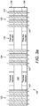


Classifications
-
- G—PHYSICS
- G01—MEASURING; TESTING
- G01N—INVESTIGATING OR ANALYSING MATERIALS BY DETERMINING THEIR CHEMICAL OR PHYSICAL PROPERTIES
- G01N27/00—Investigating or analysing materials by the use of electric, electrochemical, or magnetic means
- G01N27/62—Investigating or analysing materials by the use of electric, electrochemical, or magnetic means by investigating the ionisation of gases, e.g. aerosols; by investigating electric discharges, e.g. emission of cathode
- G01N27/622—Ion mobility spectrometry
-
- G—PHYSICS
- G01—MEASURING; TESTING
- G01N—INVESTIGATING OR ANALYSING MATERIALS BY DETERMINING THEIR CHEMICAL OR PHYSICAL PROPERTIES
- G01N27/00—Investigating or analysing materials by the use of electric, electrochemical, or magnetic means
- G01N27/62—Investigating or analysing materials by the use of electric, electrochemical, or magnetic means by investigating the ionisation of gases, e.g. aerosols; by investigating electric discharges, e.g. emission of cathode
- G01N27/622—Ion mobility spectrometry
- G01N27/624—Differential mobility spectrometry [DMS]; Field asymmetric-waveform ion mobility spectrometry [FAIMS]
-
- H—ELECTRICITY
- H01—ELECTRIC ELEMENTS
- H01J—ELECTRIC DISCHARGE TUBES OR DISCHARGE LAMPS
- H01J49/00—Particle spectrometers or separator tubes
- H01J49/0027—Methods for using particle spectrometers
- H01J49/0031—Step by step routines describing the use of the apparatus
Definitions
- the invention relates to an ion mobility filter, for example but not exclusively a field asymmetric ion mobility spectrometry filter.
- Ion mobility spectrometers are used to detect particular chemicals within gases such as air.
- DMS Differential mobility spectrometry
- FIMS field-asymmetric waveform ion mobility spectrometry
- Stability and repeatability of DMS spectra are important issues in the use of DMS in analytical applications, as explained for example in " Temperature effects in differential mobility spectrometry" by Krylov et al in International Journal of Mass Spectrometry 279 (2009) 119-125 .
- Drift gas pressure and temperature are known to influence the field dependence of ion mobility, changing peak positions in the DMS spectra and the paper by Krylov provides a model which can be used for temperature correction of DMS Spectra.
- US2005/0167587A1 describes an apparatus which supports operation of FAIMS at different temperatures to increase the separation capability of FAIMS.
- the apparatus comprises a FAIMS analyser having an analyser region for separating a subset of ions from the received ions and a temperature sensor for sensing the temperature within the analyser region.
- a temperature controller in communication with the temperature sensor controllably affects the temperature within the analyser region in response to an output signal from the temperature sensor.
- an elevation in temperature leads to peaks in a CV spectrum widening due to increased ion separation. Under such conditions, two ions that are separated at room temperature may fail to be separated at 100°C. Similarly, two ions that fail to be separated at room temperature may be separated at 10°C.
- the temperature of the FAIMS is maintained at a desired operating temperature and/or may be controllably changed from a first desired operating temperature to a second desired operating temperature for different separations.
- an ion filter for filtering ions in a gas sample comprising: a first ion channel for filtering ions from a target chemical in the gas sample; a second ion channel for filtering the ions from the target chemical in the gas sample, wherein the second ion channel is separated from the first ion channel; and a temperature control region in thermal contact with the first and second ion channels wherein, in use, the temperature control region controls a difference in temperature between the first and second ion channels.
- the ion filter may be used in a field-asymmetric waveform ion mobility spectrometry (FAIMS) and thus as explained in more detail below, the ion filter may be part of a system including a drive signal system which applies an electrical field to the ion filter.
- the drive signal system applies an oscillating electric field known as a dispersion field together with a DC voltage which provides a compensation field to the ion filter to control ion mobility of ions in the gas sample as they pass through the ion filter.
- the ion filter may be adapted to filter ion species in accordance with other known techniques.
- the ion filter may thus be adapted to filter an ion species by adjusting ion mobility of ions within the gas sample.
- Ion mobility is typically dependent on temperature.
- the temperature control region controls a difference in temperature between the first and second ion channels and thus in use, the gas sample passes through the first ion channel at a first temperature and the gas sample passes through the second ion channel at a second temperature.
- the first temperature may be lower than the second temperature or vice versa.
- the temperature difference between the first and second ion channels is preferably set so as to cause a detectable difference in ion mobility of the ions of the target species as they pass through the first and second ion channels.
- the ion filter may further comprise a third ion channel for filtering ions from the target chemical in the gas sample, wherein the third ion channel is separated from the first ion channel and the second ion channel.
- the temperature control region may be in thermal contact with the third ion channel for controlling a difference in temperature between the second and third ion channels as well as between the first and third ion channels.
- the first and second ion channels may be located within a single electrode layer which may be monolithic.
- the third and other ion channels may be located within the monolithic electrode layer.
- Using a monolithic structure may mean that all ion channels can be manufactured using standard MEMS techniques.
- small ion channel widths can be achieved resulting in large electric fields within the ion channels when applying the fields using the drive signal system.
- the gas sample is filtered at different temperatures simultaneously, which increases the likelihood that a correct chemical identification will occur because the likelihood of two chemicals having overlapping graphs at different temperatures is low. In this way, a single ion filter enables differences in ion mobility for ions in a single target chemical to be effected within cost-effective and speedy selective analysis.
- the temperature control region may comprise a thermal insulator between the first and second ion channels.
- the thermal insulator may thus prevent heat transfer from the first ion channel to the second ion channel and thus thermally isolates the first and second ion channels so that the two channels are kept at different temperatures.
- the temperature control region may comprise a thermal insulator between each adjacent pair of channels, e.g. between the second and third ion channels.
- the ion filter may comprise a continuous channel which divides the electrode layer into first and second electrode portions.
- the continuous channel may comprise a first ion channel portion defining the first ion channel and a second ion channel portion defining the second ion channel and a central channel portion connecting the first and second ion channel portions.
- third (and subsequent) ion channel portions may also be defined within the continuous channel.
- the ion filter may comprise a first electrode section having a first ion channel portion defining the first ion channel and a second electrode section having a second ion channel portion defining the second ion channel.
- the ion filter may comprise a third (and subsequent) electrode portion having a third (and subsequent) ion channel portion.
- the first ion channel portion may define a plurality of first ion channels
- the second ion channel portion may define a plurality of second ion channels and so on. There may be the same or a different number of ion channels within each portion number.
- Each of the first ion channels may have the same temperature.
- Each of the second ion channels may have the same temperature which is different to the temperature in the first ion channels.
- each of the third (or subsequent) ion channels may have the same temperature which is different to the temperature in the other ion channels.
- the thermal insulator may be mounted to the central channel portion and is thus in direct thermal contact with both the first and second ion channel.
- the thermal insulator may be positioned so that in use the thermal insulator blocks flow of ions through the portion of the monolithic layer on which it is located.
- the thermal insulator may comprise a trench which divides the electrode layer into the first electrode section and the second electrode section.
- the ion filter may be incorporated in a system in which gas flowing into the ion filter is heated before passing through the ion filter.
- the gas may heated to a number of different temperatures depending on the number of ion channels.
- gas flowing into the first ion channel(s) may be heated to temperature T1 and the gas flowing into the first ion channel(s) being heated to temperature T2.
- the ion filter may comprise a first funnel portion which in use directs gas flow at temperature T1 into the first ion channel portion and a second funnel portion which in use channels gas flow at temperature T2 into the second ion channel portion.
- the ion filter may comprise a third (or subsequent) funnel portion which in use directs gas flow at temperature T3 into the third (or subsequent) ion channel portion.
- the thermal insulator may be located between adjacent funnel portions.
- the temperature control region may comprise a heating layer mounted to the electrode layer, the heating layer comprising at least one heating element for controlling the temperature within the first and second ion channels.
- the combination of heating and electrode layer may be manufactured in same MEMS process as for monolithic layer.
- the heating layer may be mounted directly to the electrode layer or mounted to the electrode layer via an insulating layer.
- the at least one heating element may be aligned with the first ion channel and the second ion channel whereby the heating element is configured to heat the first ion channel to a first temperature and the second ion channel to a second temperature.
- the at least one heating element may be aligned with the third (or subsequent) ion channel to heat the third (or subsequent) ion channel to a third (or subsequent) temperature.
- the heating element may be a continuous wire (e.g. tungsten) embedded in an insulating material (e.g. polymer).
- the ion filter may comprise a heating element aligned at a side of each one of the first and second ion channels (and at a side of the third and subsequent ion channels where needed).
- the first ion channel may be defined between a first pair of electrodes and the second ion channel may be defined between a second pair of electrodes.
- the third and subsequent ion channels may be defined between a corresponding pair of electrodes. These pair of electrodes may be in the form of interdigitated electrode fingers.
- the first heating element may be aligned (e.g. overlap) with one of the first pair of electrodes and the second heating element may be aligned (e.g. overlap) with one of the second pair of electrodes. There may be heating elements aligned with each of the electrodes. By aligning the heating elements with the individual electrodes, it may be possible to control the temperature within each individual ion channels separately.
- the ion filter may comprise a second heating layer on an opposed side of the electrode layer to the heating layer.
- the second heating layer may be similar to the first heating layer and thus the second heating layer is configured to heat the first ion channel to a first temperature and the second ion channel to a second temperature.
- Both heating layers may be controlled to ensure that the temperature along each ion channel is constant.
- the heating layers may be operated at different temperatures to create a thermal gradient within an ion channel although it is noted that the resulting spectrum is likely to be more difficult to analyse. By keeping the temperature along each channel constant, there is a level of discretisation which means that it is likely to be easier to perform subsequent analysis.
- the ion filter may comprise a plurality of ion channels between the first ion channel and the second ion channel wherein the temperature control region comprises a first heater mounted adjacent the first ion channel to heat the first ion channel to a first temperature and a second heater mounted adjacent the second ion channel to heat the second ion channel to a second temperature.
- the first and second heaters may thus create a thermal gradient across the ion filter with each of the ion channels having a different temperature. In this way, many ion channel temperatures are possible but only two temperatures need to be controlled.
- the first and second heaters may be incorporated in the heating layer(s) described above.
- the ion filter may comprise a first electrode layer having the first ion channel and second electrode layer having the second ion channel wherein the temperature control region comprises a thermal insulator between the first electrode layer and the second electrode layer.
- the gas flows first through the first ion channel and then through the second ion channel.
- the first and second ion channels filter the same ion flow in series.
- the ion filter may comprise a third or subsequent ion electrode layer with each electrode layer separated by a thermal insulator.
- the described ion filters may be incorporated in a spectrometry system and thus we also describe an ion mobility spectrometry system comprising: an ion filter as above; an ionizer for generating the ions with the gas sample; and a detector for detecting the output from the ion filter.
- the detector may comprise a detecting element, e.g. a pair of detector electrodes, for each ion channel.
- the system may comprise a processor configured to generate a graphical output for each ion channel; the graphical output may be based on information, e.g. ion current, which is detected by the detector. By generating a graphical output for each ion channel, an output for the target chemical is produced at two different temperatures. This may aid identification of the target chemical.
- the processor may be configured to generate a measurement of ion current at the detector as a function of an applied dispersion field and an applied compensation field for each ion channel.
- the system may thus comprise a drive signal system for applying the dispersion field and the compensation field. It will be appreciated that by using a detector which comprises a separate detecting element for each ion channel that such an output may be more easily generated but the processor may be configured to generate the output from a different style of detector.
- the ion filter described above can also be used to filter ions.
- a method of filtering ions from a target chemical in a gas sample comprising: passing the gas sample through a first ion channel for filtering ions from a target chemical in the gas sample; passing the gas sample through a second ion channel for filtering ions from the target chemical in the gas sample, wherein the second ion channel is separated from the first ion channel and is at a different temperature to that of the first ion channel.
- the gas sample may be passed through the first and second ion channels simultaneously. Alternatively, the gas sample may be passed through the first and second ion channels sequentially.
- the method may also incorporate the features described above in relation to the ion filter.
- a method of detecting ions from a target chemical in a gas sample comprising: ionizing the gas sample to create ions of the target chemical; filtering the ions as described above; and detecting the ions that output from the filter using a detector.
- the method may also incorporate the features described above in relation to the system.
- Figures 1a to 1d shows a schematic illustration of a spectrometry system which may be a miniature device as described in " Characterisation of a miniature, ultra-high field, ion mobility spectrometer" by Wilks et al published in Int. J. Ion Mobil Spec. (2012) 15:199-222 .
- gas flows into an ionizer 10 and the generated ions then pass through an ion filter 12.
- the ion filter separates the ions and may thus be termed an ion separator.
- the ion filter has a plurality of ion channels each having a small gap width (g of around 30 to 50 ⁇ m) and relatively short length (e.g. L around 300 ⁇ m).
- the gap surfaces are made of high-conductivity silicon (or similar material) and are electrically connected via wire bonding to metal pads on the face of the silicon. Ions exiting from the ion separator are detected by an ion detector 14. It is known that temperature and pressure can affect the results and thus a temperature sensor 16 and/or a pressure sensor 18 may also be included in the system. These are shown schematically on the output gas flow but could be incorporated into another appropriate location within the device.
- an oscillating electric field is applied to the ion separator.
- a variable high-voltage asymmetric waveform of low voltage pulse duration t(s) and high voltage pulse duration ⁇ ( s ) and peak voltage V D is applied to create the variable field of V D / g (kVcm -1 ).
- the mobility of each ion within the ion separator oscillates between a low-field mobility K 0 and a high-field mobility K E and the difference between the high-field mobility and low field mobility is termed ⁇ K.
- Ions of different chemicals will have different values of ⁇ K and the ions adopt a net longitudinal drift path length ( d h - d t ) through the ion filter which is determined by their high and low field drift velocity ( v D(h) and v D(l) ) and the high field and low field pulse durations. Only ions in a "balanced" condition such as the middle ion in Figure 1b will exit from the ion separator and be detected by the ion detector. Ions which contact either of the sides of the ion channel will not be detected.
- a bias DC "tuning voltage" ( V c ) is applied on top of the applied waveform to enable subtle adjustment of the peak voltage V D to counter the drift experienced by an ion of a specific ⁇ K .
- a drive signal system 130 applies the asymmetric waveform and the tuning voltage to the ion filter 100 as described above.
- the output ions from the ion filter 100 are detected by the detector 110.
- the output from the detector 110 is sent to a processor 120 which may be local (i.e. within the ion filter) or remote (i.e. in a separate computer/server).
- the processor is adapted to extract numerical parameters which facilitate chemical detection, identification, classification and/or quantification of the ions.
- the processor may be configured to generate an output as shown in Figure 1d in which the measurement of ion current at the detector is plotted as a function of the applied electric field resulting from the asymmetric waveform which is known as the dispersion field E D (kVcm -1 ) and the applied electric field resulting from the DC voltage which is known as the compensation field E C (kVcm -1 ).
- the spectral output may alternatively be presented as an mxn matrix of ion current measurements at m compensation field and n dispersion field settings.
- Figure 1d shows the E C :E D peak trajectories for monomer and dimers of acetone, 2-butanone and dimethyl methyl phosphonate (DMMP). These trajectories are used to identify whether ions of a particular chemical are present in a gas sample by comparing the resulting graph with previously collected graphs of known chemicals generated under the same conditions. However, as illustrated in Figure 1d , the graphs for some chemicals are similar and thus identification is more difficult when the differences are less pronounced. This is particularly true for relatively large molecules which tend to cluster together when FAIMS is operated at room temperature.
- DMMP dimethyl methyl phosphonate
- T eff T + ⁇ MK 0 2 N 0 2 E D N 2 3 k b
- T the neutral gas temperature
- ⁇ is the ion-neutral collision efficiency factor
- M is the molecular weight of the drift gas
- K 0 is the mobility coefficient under low field conditions
- N 0 is the standard gas density
- E D /N is the dispersion field in Townsend
- N is the gas density
- k b is Boltzmann's gas constant.
- FIGS 2a and 2b are schematic illustrations of an ion filter 20 which can be incorporated in the systems shown in Figures 1a to 1d .
- the ion filter 20 comprises a monolithic electrode layer 30.
- the continuous channel separates the ion filter into first and second electrode portions 32, 34.
- the channel comprises a first ion channel portion 22 and a second ion channel portion 24 separated by a central channel portion.
- each of the first and second ion channel portions comprises a plurality of ion channels 27 through which ions flow.
- An insulator 26 is mounted to the monolithic electrode layer above the central channel portion. In this way, the insulator 26 is in thermal contact with both the first ion channel portion 22 and the second ion channel portion 24.
- a heater may be incorporated into each funnel portion or the heater may be downstream from each funnel portion so that the ions are heated before entering the funnel portion, e.g. on exiting the ionizer.
- the insulator 26 is between the first and a second funnel portion 36, 38 and thermally insulates the first and second funnel portions from one another.
- the insulator 26 thus acts as a temperature control region which ensures that the difference in temperature between the gas samples in the first and second ion channel portions is maintained.
- the effective temperature of an ion is dependent on the gas temperature and thus the ion mobility for the ions passing into each of the first and second channel portions will be different even though the same dispersion field is being applied to both portions.
- the same compensation field is also applied to both channel portions and since the aim is to detect the same chemical using both portions, the compensation field will need to be selected carefully to ensure that the ions of the particular chemical to be detected, i.e. the correct ions species, are "balanced" and are output from both the first and second ion channels despite the differences in temperature.
- Figure 2c shows an example output from the filter of Figures 2a and 2b .
- the ion current is plotted as a function of both the compensation and dispersion fields for both the first and second ion channel portions.
- Figure 2c shows a clear difference between the graphs at the first temperature a and the second temperature b.
- both ion channel portions are serpentine and each defines three interdigitated electrodes 28. It will be appreciated that the number of electrodes 28 shown is merely illustrative and a different number may be used. Similarly, it will be appreciated that different shapes of ion channel may also be used. Furthermore, whilst the complexity of the device would be increased, it will be appreciated that more than two channel portions could be used provided adjacent portions were insulated from each other as described above. By incorporating interdigitated electrodes, the ion filter may have high ion channel density and large electric fields.
- Figures 3a and 3b show an alternative version of an ion filter which can be incorporated in the system of Figures 1a to 1d .
- the ion filter 120 comprises an electrode layer 130 having a continuous channel 121 which separates the ion filter into first and second electrode portions 132, 134.
- the continuous channel comprises a first ion channel portion 122, a second ion channel portion 124 and a third ion channel portion 126 separated by first and second intermediate channel portions respectively.
- the ion channel portions are serpentine and each defines three interdigitated electrodes 128 which extend as fingers from either of the first or second electrode portions.
- At least one heating layer 136 is mounted to the electrode layer 130 and as shown in this example, a heating layer 136 is mounted to both surfaces of the electrode layer 130.
- the heating layer is more clearly shown in Figure 3b .
- the heating layer comprises a heating element 138 in the form of a tungsten (or similar) wire which is embedded in a polymer layer.
- the heating element 138 has a shape which matches the shape of the ion channel, in this case a serpentine shape. Accordingly, the heating element 138 sits within the gap between each electrode.
- Each heating layer 136 comprises a pair of thermal insulators 125; one between each pair of ion channel portions. In this arrangement the thermal insulators 125 are embedded in the polymer layer. They are thus in indirect thermal contact with each of the pairs of ion channel portions via part of the polymer layer.
- the heating element 138 heats the first ion channel portion 122 to a first temperature.
- the second ion channel portion 124 is heated to a second temperature and the third ion channel portion 126 to a third temperature.
- the first temperature is lower than the second temperature which is itself lower that the third temperature and thus the temperatures may be termed low, moderate and high respectively.
- the use of a single heating layer should provide the required difference in temperature between each ion channel portion and may provide a consistent temperature through the entire depth of the channel (i.e. from one face of the electrode layer to the other).
- the use of a heating layer on both surfaces of the electrode layer should ensure that the ion channel has a consistent temperature through the entire depth of the channel (i.e. from one face of the electrode layer to the other).
- each heating layer may comprise a flexible PCB with coated heating elements which are aligned with the electrodes and ceramic (or similar material) thermal insulator(s) between each ion channel portion.
- a schematic representation of this arrangement is shown in Figure 3c in which an insulating layer 325 is adjacent an electrode layer 330 in which the ion channels and electrodes may be formed as described above.
- the heating elements 338 are mounted on the insulating layer 323.
- thin film resistive heating coatings may be applied to each surface of the electrode layer overlapping the electrodes. Each coating may be set at a different level for each ion channel portion.
- Figures 4a and 4b show an alternative design of ion filter comprising an electrode layer having a plurality of electrodes 228 with an ion channel between each pair of electrodes.
- the plurality of electrodes 228 may be formed as explained in relation to Figures 2a to 3b , e.g. an interdigitated set of electrodes.
- the electrode layer is supported on a substrate 220 which supports the electrodes and maintains the gap width of each ion channel.
- a substrate may be incorporated in the other embodiments as needed.
- a heater 200a, 200b is positioned on each side of the ion filter.
- a first heater 200a heats one side of the ion filter to a first relatively low temperature, e.g. 50° and a second heater 200b heats the opposed side of the ion filter to a second relatively high temperature, e.g. 200°.
- each ion channel 227 has a different temperature.
- the two heaters together with the thermal properties of the ion filter thus effectively form a temperature controller which controls a difference in temperature between the gas samples in each ion channel.
- the resulting E C :E D spectrum comprises a peak trajectory for each temperature. This may be measured by a single detector layer which is able to correctly identify the ion current output from each ion channel.
- the detector layer 230 may comprise a plurality of detectors, each adjacent an electrode to detect the ion current output from each ion channel.
- the ion channels are arranged side-by-side so that the ions flow through at the same time.
- Figure 5 shows an alternative arrangement in which ion channels are arranged in tandem, i.e. the ions first flow through a first ion channel 327a and subsequently through a second ion channel 327b.
- a plurality of ion channels may be arranged in tandem, for example by layering two electrode layers such as those used in other embodiments.
- the first ion channel is heated by a first heater to a first temperature T1 and the second ion channel is heated by a second heater to a second temperature T2.
- T1 may be lower than T2 or vice versa.
- the two temperatures are selected to provide a resulting E C :E D spectrum having two separate graphs which enable the desired chemical to be identified by the system.
- the heaters are shown schematically to one side of each channel but may be any suitable form of heating.
- a thermal insulator 325 is positioned between the channels. The thermal insulator in combination with the heaters form a temperature controller which controls a difference in temperature between the gas samples in the first and second ion channels.
- FIG 6 shows a variation of the arrangement of Figure 2a .
- the ion filter 420 comprises a monolithic electrode layer 430 which is divided into two sections by an insulating trench 426.
- the continuous channel is replaced by two separate ion channel portions 422, 424; one in each section of the electrode layer.
- the channel portions are arranged side-by-side and divide the ion filter into two first and second electrode portions 432a,b, 434a,b.
- each of the separate channel portions comprises a plurality of ion channels through which ions flow with the first channel portion comprising a plurality of first ion channels and the second channel portion comprising a plurality of second ion channels.
- the electrode layer 430 is supported on a substrate 440 which maintains the electrode sections and also the electrode portions in fixed alignment to ensure that the ion channel gap width is maintained.
- the first channel portion and 422 (and thus the first ion channels) is heated to a first temperature and the second channel 424 (and thus the second ion channels) to a second, different temperature.
- the two temperatures are selected to provide a resulting E C :E D spectrum having two separate graphs which enable the desired chemical to be identified by the system.
Landscapes
- Physics & Mathematics (AREA)
- Chemical & Material Sciences (AREA)
- Spectroscopy & Molecular Physics (AREA)
- Analytical Chemistry (AREA)
- Health & Medical Sciences (AREA)
- Electrochemistry (AREA)
- Chemical Kinetics & Catalysis (AREA)
- Life Sciences & Earth Sciences (AREA)
- Biochemistry (AREA)
- General Health & Medical Sciences (AREA)
- General Physics & Mathematics (AREA)
- Immunology (AREA)
- Pathology (AREA)
- Other Investigation Or Analysis Of Materials By Electrical Means (AREA)
Description
- The invention relates to an ion mobility filter, for example but not exclusively a field asymmetric ion mobility spectrometry filter.
- Ion mobility spectrometers are used to detect particular chemicals within gases such as air. Differential mobility spectrometry (DMS) which is also known as field-asymmetric waveform ion mobility spectrometry (FAIMS) is recognised as a powerful tool for separation and characterization of gas-phase ions. Stability and repeatability of DMS spectra are important issues in the use of DMS in analytical applications, as explained for example in " Temperature effects in differential mobility spectrometry" by Krylov et al in International Journal of Mass Spectrometry 279 (2009) 119-125. Drift gas pressure and temperature are known to influence the field dependence of ion mobility, changing peak positions in the DMS spectra and the paper by Krylov provides a model which can be used for temperature correction of DMS Spectra.
-
US2005/0167587A1 describes an apparatus which supports operation of FAIMS at different temperatures to increase the separation capability of FAIMS. The apparatus comprises a FAIMS analyser having an analyser region for separating a subset of ions from the received ions and a temperature sensor for sensing the temperature within the analyser region. A temperature controller in communication with the temperature sensor controllably affects the temperature within the analyser region in response to an output signal from the temperature sensor. As explained inUS2005/0167587A1 an elevation in temperature leads to peaks in a CV spectrum widening due to increased ion separation. Under such conditions, two ions that are separated at room temperature may fail to be separated at 100°C. Similarly, two ions that fail to be separated at room temperature may be separated at 10°C. The temperature of the FAIMS is maintained at a desired operating temperature and/or may be controllably changed from a first desired operating temperature to a second desired operating temperature for different separations. - The applicant has also recognised the need for an alternative solution for selectively distinguishing particular chemicals.
- According to the present invention there is provided an apparatus as set forth in the appended claims. Other features of the invention will be apparent from the dependent claims, and the description which follows.
- We describe an ion filter for filtering ions in a gas sample, comprising: a first ion channel for filtering ions from a target chemical in the gas sample; a second ion channel for filtering the ions from the target chemical in the gas sample, wherein the second ion channel is separated from the first ion channel; and a temperature control region in thermal contact with the first and second ion channels wherein, in use, the temperature control region controls a difference in temperature between the first and second ion channels.
- The ion filter may be used in a field-asymmetric waveform ion mobility spectrometry (FAIMS) and thus as explained in more detail below, the ion filter may be part of a system including a drive signal system which applies an electrical field to the ion filter. In use, the drive signal system applies an oscillating electric field known as a dispersion field together with a DC voltage which provides a compensation field to the ion filter to control ion mobility of ions in the gas sample as they pass through the ion filter. In this way, only ions of particular or target chemical species pass through the ion filter and ions of other chemical species contact the ion filter and are thus filtered out of the gas sample. Alternatively, the ion filter may be adapted to filter ion species in accordance with other known techniques. The ion filter may thus be adapted to filter an ion species by adjusting ion mobility of ions within the gas sample.
- Ion mobility is typically dependent on temperature. The temperature control region controls a difference in temperature between the first and second ion channels and thus in use, the gas sample passes through the first ion channel at a first temperature and the gas sample passes through the second ion channel at a second temperature. The first temperature may be lower than the second temperature or vice versa. The temperature difference between the first and second ion channels is preferably set so as to cause a detectable difference in ion mobility of the ions of the target species as they pass through the first and second ion channels.
- The ion filter may further comprise a third ion channel for filtering ions from the target chemical in the gas sample, wherein the third ion channel is separated from the first ion channel and the second ion channel. The temperature control region may be in thermal contact with the third ion channel for controlling a difference in temperature between the second and third ion channels as well as between the first and third ion channels. There may be further ion channels each having a different temperature to the other ion channels.
- The first and second ion channels may be located within a single electrode layer which may be monolithic. Similarly, the third and other ion channels may be located within the monolithic electrode layer. Using a monolithic structure may mean that all ion channels can be manufactured using standard MEMS techniques. Furthermore, small ion channel widths can be achieved resulting in large electric fields within the ion channels when applying the fields using the drive signal system. By including the ion channels in the same layer, the gas sample is filtered at different temperatures simultaneously, which increases the likelihood that a correct chemical identification will occur because the likelihood of two chemicals having overlapping graphs at different temperatures is low. In this way, a single ion filter enables differences in ion mobility for ions in a single target chemical to be effected within cost-effective and speedy selective analysis.
- The temperature control region may comprise a thermal insulator between the first and second ion channels. The thermal insulator may thus prevent heat transfer from the first ion channel to the second ion channel and thus thermally isolates the first and second ion channels so that the two channels are kept at different temperatures. Similarly, in an ion filter having a third (or subsequent) channel, the temperature control region may comprise a thermal insulator between each adjacent pair of channels, e.g. between the second and third ion channels.
- The ion filter may comprise a continuous channel which divides the electrode layer into first and second electrode portions. The continuous channel may comprise a first ion channel portion defining the first ion channel and a second ion channel portion defining the second ion channel and a central channel portion connecting the first and second ion channel portions. Similarly, in an ion filter having a third (or subsequent) ion channel, third (and subsequent) ion channel portions may also be defined within the continuous channel. Alternatively, the ion filter may comprise a first electrode section having a first ion channel portion defining the first ion channel and a second electrode section having a second ion channel portion defining the second ion channel. Similarly, in an ion filter having a third (or subsequent) ion channel, the ion filter may comprise a third (and subsequent) electrode portion having a third (and subsequent) ion channel portion. In all arrangements, the first ion channel portion may define a plurality of first ion channels, the second ion channel portion may define a plurality of second ion channels and so on. There may be the same or a different number of ion channels within each portion number. Each of the first ion channels may have the same temperature. Each of the second ion channels may have the same temperature which is different to the temperature in the first ion channels. Similarly, in an ion filter having a third (or subsequent) ion channel, each of the third (or subsequent) ion channels may have the same temperature which is different to the temperature in the other ion channels.
- In the continuous channel arrangement, the thermal insulator may be mounted to the central channel portion and is thus in direct thermal contact with both the first and second ion channel. The thermal insulator may be positioned so that in use the thermal insulator blocks flow of ions through the portion of the monolithic layer on which it is located. In the alternative arrangement, the thermal insulator may comprise a trench which divides the electrode layer into the first electrode section and the second electrode section. These arrangements provide a simple mechanical control of temperature.
- The ion filter may be incorporated in a system in which gas flowing into the ion filter is heated before passing through the ion filter. The gas may heated to a number of different temperatures depending on the number of ion channels. For example, for a device having first and second ion channels, gas flowing into the first ion channel(s) may be heated to temperature T1 and the gas flowing into the first ion channel(s) being heated to temperature T2. The ion filter may comprise a first funnel portion which in use directs gas flow at temperature T1 into the first ion channel portion and a second funnel portion which in use channels gas flow at temperature T2 into the second ion channel portion. Similarly, in an ion filter having a third (or subsequent) ion channel, the ion filter may comprise a third (or subsequent) funnel portion which in use directs gas flow at temperature T3 into the third (or subsequent) ion channel portion. The thermal insulator may be located between adjacent funnel portions.
- The temperature control region may comprise a heating layer mounted to the electrode layer, the heating layer comprising at least one heating element for controlling the temperature within the first and second ion channels. The combination of heating and electrode layer may be manufactured in same MEMS process as for monolithic layer. The heating layer may be mounted directly to the electrode layer or mounted to the electrode layer via an insulating layer.
- The at least one heating element may be aligned with the first ion channel and the second ion channel whereby the heating element is configured to heat the first ion channel to a first temperature and the second ion channel to a second temperature. Similarly, in an ion filter having a third (or subsequent) ion channel, the at least one heating element may be aligned with the third (or subsequent) ion channel to heat the third (or subsequent) ion channel to a third (or subsequent) temperature. The heating element may be a continuous wire (e.g. tungsten) embedded in an insulating material (e.g. polymer). Alternatively, there may be a plurality of heating elements, for example the ion filter may comprise a heating element aligned at a side of each one of the first and second ion channels (and at a side of the third and subsequent ion channels where needed).
- The first ion channel may be defined between a first pair of electrodes and the second ion channel may be defined between a second pair of electrodes. Similarly, the third and subsequent ion channels may be defined between a corresponding pair of electrodes. These pair of electrodes may be in the form of interdigitated electrode fingers. The first heating element may be aligned (e.g. overlap) with one of the first pair of electrodes and the second heating element may be aligned (e.g. overlap) with one of the second pair of electrodes. There may be heating elements aligned with each of the electrodes. By aligning the heating elements with the individual electrodes, it may be possible to control the temperature within each individual ion channels separately.
- The ion filter may comprise a second heating layer on an opposed side of the electrode layer to the heating layer. The second heating layer may be similar to the first heating layer and thus the second heating layer is configured to heat the first ion channel to a first temperature and the second ion channel to a second temperature. Both heating layers may be controlled to ensure that the temperature along each ion channel is constant. Alternatively, the heating layers may be operated at different temperatures to create a thermal gradient within an ion channel although it is noted that the resulting spectrum is likely to be more difficult to analyse. By keeping the temperature along each channel constant, there is a level of discretisation which means that it is likely to be easier to perform subsequent analysis.
- The ion filter may comprise a plurality of ion channels between the first ion channel and the second ion channel wherein the temperature control region comprises a first heater mounted adjacent the first ion channel to heat the first ion channel to a first temperature and a second heater mounted adjacent the second ion channel to heat the second ion channel to a second temperature. The first and second heaters may thus create a thermal gradient across the ion filter with each of the ion channels having a different temperature. In this way, many ion channel temperatures are possible but only two temperatures need to be controlled. The first and second heaters may be incorporated in the heating layer(s) described above.
- The ion filter may comprise a first electrode layer having the first ion channel and second electrode layer having the second ion channel wherein the temperature control region comprises a thermal insulator between the first electrode layer and the second electrode layer. In use, the gas flows first through the first ion channel and then through the second ion channel. The first and second ion channels filter the same ion flow in series. In an arrangement having a third or subsequent ion channel, the ion filter may comprise a third or subsequent ion electrode layer with each electrode layer separated by a thermal insulator. Although the sample is not measured at different temperatures simultaneously in this arrangement, a single ion filter still allows multiple different temperatures to be measured in a simple manner.
- As set out above, the described ion filters may be incorporated in a spectrometry system and thus we also describe an ion mobility spectrometry system comprising: an ion filter as above; an ionizer for generating the ions with the gas sample; and a detector for detecting the output from the ion filter. The detector may comprise a detecting element, e.g. a pair of detector electrodes, for each ion channel.
- The system may comprise a processor configured to generate a graphical output for each ion channel; the graphical output may be based on information, e.g. ion current, which is detected by the detector. By generating a graphical output for each ion channel, an output for the target chemical is produced at two different temperatures. This may aid identification of the target chemical. The processor may be configured to generate a measurement of ion current at the detector as a function of an applied dispersion field and an applied compensation field for each ion channel. The system may thus comprise a drive signal system for applying the dispersion field and the compensation field. It will be appreciated that by using a detector which comprises a separate detecting element for each ion channel that such an output may be more easily generated but the processor may be configured to generate the output from a different style of detector.
- It will be appreciated that the ion filter described above can also be used to filter ions. Thus, we also describe a method of filtering ions from a target chemical in a gas sample, the method comprising: passing the gas sample through a first ion channel for filtering ions from a target chemical in the gas sample; passing the gas sample through a second ion channel for filtering ions from the target chemical in the gas sample, wherein the second ion channel is separated from the first ion channel and is at a different temperature to that of the first ion channel.
- The gas sample may be passed through the first and second ion channels simultaneously. Alternatively, the gas sample may be passed through the first and second ion channels sequentially. The method may also incorporate the features described above in relation to the ion filter.
- We also describe a method of detecting ions from a target chemical in a gas sample, the method comprising: ionizing the gas sample to create ions of the target chemical; filtering the ions as described above; and detecting the ions that output from the filter using a detector. The method may also incorporate the features described above in relation to the system.
- For a better understanding of the invention, and to show how embodiments of the same may be carried into effect, reference will now be made, by way of example only, to the accompanying diagrammatic drawings in which:
-
Figure 1a is a schematic illustration of a spectrometry system; -
Figure 1b is a schematic illustration of a channel within an ion filter in the system ofFigure 1a ; -
Figure 1c is an alternative schematic illustration of the spectrometry system ofFigure 1a ; -
Figure 1d is an example of the output from the system ofFigure 1c ; -
Figures 2a and 2b show cross-sectional and plan views respectively of a first ion filter; -
Figure 2c shows a spectrum obtained using an ion filter; -
Figures 3a and3b show cross-sectional and plan views respectively of a second ion filter; -
Figure 3c show a cross-sectional view of a variation of the second ion filter; -
Figures 4a and 4b shows cross-sectional views of two variations of another ion filter; -
Figure 5 shows a partial cross-sectional view of another ion filter; and -
Figure 6 is a plan view of another filter. -
Figures 1a to 1d shows a schematic illustration of a spectrometry system which may be a miniature device as described in "Characterisation of a miniature, ultra-high field, ion mobility spectrometer" by Wilks et al published in Int. J. Ion Mobil Spec. (2012) 15:199-222. As shown inFigure 1a , gas flows into anionizer 10 and the generated ions then pass through anion filter 12. The ion filter separates the ions and may thus be termed an ion separator. In the illustrated example, the ion filter has a plurality of ion channels each having a small gap width (g of around 30 to 50 µm) and relatively short length (e.g. L around 300 µm). The gap surfaces are made of high-conductivity silicon (or similar material) and are electrically connected via wire bonding to metal pads on the face of the silicon. Ions exiting from the ion separator are detected by anion detector 14. It is known that temperature and pressure can affect the results and thus atemperature sensor 16 and/or apressure sensor 18 may also be included in the system. These are shown schematically on the output gas flow but could be incorporated into another appropriate location within the device. - As shown in
Figure 1b , an oscillating electric field is applied to the ion separator. A variable high-voltage asymmetric waveform of low voltage pulse duration t(s) and high voltage pulse duration τ(s) and peak voltage VD is applied to create the variable field of VD /g (kVcm-1). The mobility of each ion within the ion separator oscillates between a low-field mobility K0 and a high-field mobility KE and the difference between the high-field mobility and low field mobility is termed ΔK. Ions of different chemicals will have different values of ΔK and the ions adopt a net longitudinal drift path length (dh -dt ) through the ion filter which is determined by their high and low field drift velocity (vD(h) and vD(l)) and the high field and low field pulse durations. Only ions in a "balanced" condition such as the middle ion inFigure 1b will exit from the ion separator and be detected by the ion detector. Ions which contact either of the sides of the ion channel will not be detected. A bias DC "tuning voltage" (Vc ) is applied on top of the applied waveform to enable subtle adjustment of the peak voltage VD to counter the drift experienced by an ion of a specific ΔK. - As shown schematically in
Figure 1c , adrive signal system 130 applies the asymmetric waveform and the tuning voltage to theion filter 100 as described above. The output ions from theion filter 100 are detected by thedetector 110. The output from thedetector 110 is sent to aprocessor 120 which may be local (i.e. within the ion filter) or remote (i.e. in a separate computer/server). The processor is adapted to extract numerical parameters which facilitate chemical detection, identification, classification and/or quantification of the ions. For example, the processor may be configured to generate an output as shown inFigure 1d in which the measurement of ion current at the detector is plotted as a function of the applied electric field resulting from the asymmetric waveform which is known as the dispersion field ED (kVcm-1) and the applied electric field resulting from the DC voltage which is known as the compensation field EC (kVcm-1). The spectral output may alternatively be presented as an mxn matrix of ion current measurements at m compensation field and n dispersion field settings. -
Figure 1d shows the EC:ED peak trajectories for monomer and dimers of acetone, 2-butanone and dimethyl methyl phosphonate (DMMP). These trajectories are used to identify whether ions of a particular chemical are present in a gas sample by comparing the resulting graph with previously collected graphs of known chemicals generated under the same conditions. However, as illustrated inFigure 1d , the graphs for some chemicals are similar and thus identification is more difficult when the differences are less pronounced. This is particularly true for relatively large molecules which tend to cluster together when FAIMS is operated at room temperature. - As explained in the background section, temperature is a factor which affects the output from the filter. At higher electric fields (such as those used in FAIMS), ions acquire substantial energy from the field and the frequency and strength of the ion-neutral interaction changes. As a result the mobility coefficient KE at fixed bulk gas temperature becomes dependent on the electric field as shown:

- Where K0 is the mobility coefficient under low field conditions, α(E) is a non-dimensional function characterising the field mobility dependence (called the alpha function) and ED is the dispersion field. Temperature affects the ion mobility in two ways, namely by changing gas density, N. In addition, gas temperature changes the ion and neutral kinetic energy distributions and hence changes the distribution of ion-neutral collision energies and the ion mobility. The effective temperature of an ion Teff may be defined as:

- As shown above, the effective temperature of an ion Teff is a factor of both the temperature in the absence of an electric field and the electric field.
Figures 2a and 2b are schematic illustrations of an ion filter 20 which can be incorporated in the systems shown inFigures 1a to 1d . In this arrangement, the ion filter 20 comprises amonolithic electrode layer 30. The continuous channel separates the ion filter into first andsecond electrode portions ion channel portion 22 and a secondion channel portion 24 separated by a central channel portion. As shown more clearly inFigure 2b , each of the first and second ion channel portions comprises a plurality ofion channels 27 through which ions flow. Aninsulator 26 is mounted to the monolithic electrode layer above the central channel portion. In this way, theinsulator 26 is in thermal contact with both the firstion channel portion 22 and the secondion channel portion 24. - Ions flow through a
first funnel portion 36 into the firstion channel portion 22 and through asecond funnel portion 38 into the secondion channel portion 24. Thefunnel portions first funnel portion 36 are heated to a first temperature, for example a=65° and ions flowing through thesecond funnel portion 38 are heated to a second different temperature, for example b=50°. A heater may be incorporated into each funnel portion or the heater may be downstream from each funnel portion so that the ions are heated before entering the funnel portion, e.g. on exiting the ionizer. Theinsulator 26 is between the first and asecond funnel portion insulator 26 thus acts as a temperature control region which ensures that the difference in temperature between the gas samples in the first and second ion channel portions is maintained. - As set out above, the effective temperature of an ion is dependent on the gas temperature and thus the ion mobility for the ions passing into each of the first and second channel portions will be different even though the same dispersion field is being applied to both portions. The same compensation field is also applied to both channel portions and since the aim is to detect the same chemical using both portions, the compensation field will need to be selected carefully to ensure that the ions of the particular chemical to be detected, i.e. the correct ions species, are "balanced" and are output from both the first and second ion channels despite the differences in temperature.
-
Figure 2c shows an example output from the filter ofFigures 2a and 2b . The ion current is plotted as a function of both the compensation and dispersion fields for both the first and second ion channel portions.Figure 2c shows a clear difference between the graphs at the first temperature a and the second temperature b. These two graphs can then be matched with known graphs collected under the same conditions to detect and identify a particular chemical. By measuring ions at two different temperatures simultaneously, this increases the likelihood that a correct chemical identification will occur because the likelihood of two chemicals having overlapping graphs at two different temperatures is low. Furthermore, running at two different temperatures simultaneously is more efficient than operating the system twice, once at each temperature and thus the chemical identification process is less time consuming. - In this illustration, both ion channel portions are serpentine and each defines three interdigitated
electrodes 28. It will be appreciated that the number ofelectrodes 28 shown is merely illustrative and a different number may be used. Similarly, it will be appreciated that different shapes of ion channel may also be used. Furthermore, whilst the complexity of the device would be increased, it will be appreciated that more than two channel portions could be used provided adjacent portions were insulated from each other as described above. By incorporating interdigitated electrodes, the ion filter may have high ion channel density and large electric fields. -
Figures 3a and3b show an alternative version of an ion filter which can be incorporated in the system ofFigures 1a to 1d . In contrast to the arrangement shown inFigures 2a and 2b , there is direct heating of the ion filter rather than heating of the ions before entering the ion filter. As shown inFigures 3a and3b , theion filter 120 comprises anelectrode layer 130 having acontinuous channel 121 which separates the ion filter into first andsecond electrode portions ion channel portion 122, a secondion channel portion 124 and a thirdion channel portion 126 separated by first and second intermediate channel portions respectively. As in the previous embodiment, the ion channel portions are serpentine and each defines three interdigitatedelectrodes 128 which extend as fingers from either of the first or second electrode portions. There are a plurality ofion channels 127 in each of the first, second and third ion channel portions through which ions flow as schematically illustrated by the arrows. It will be appreciated that any number of fingers (interdigitated electrodes) and/or channels can be used. Moreover, in the arrangement, the same number of electrodes and channels are present in each portion but this need not be the case. - At least one
heating layer 136 is mounted to theelectrode layer 130 and as shown in this example, aheating layer 136 is mounted to both surfaces of theelectrode layer 130. The heating layer is more clearly shown inFigure 3b . In this embodiment, the heating layer comprises aheating element 138 in the form of a tungsten (or similar) wire which is embedded in a polymer layer. Theheating element 138 has a shape which matches the shape of the ion channel, in this case a serpentine shape. Accordingly, theheating element 138 sits within the gap between each electrode. Eachheating layer 136 comprises a pair ofthermal insulators 125; one between each pair of ion channel portions. In this arrangement thethermal insulators 125 are embedded in the polymer layer. They are thus in indirect thermal contact with each of the pairs of ion channel portions via part of the polymer layer. - The
heating element 138 heats the firstion channel portion 122 to a first temperature. The secondion channel portion 124 is heated to a second temperature and the thirdion channel portion 126 to a third temperature. The first temperature is lower than the second temperature which is itself lower that the third temperature and thus the temperatures may be termed low, moderate and high respectively. By measuring ions at three different temperatures simultaneously, this increases the likelihood that a correct chemical identification will occur because the likelihood of two chemicals having overlapping graphs at three different temperatures is low. The use of a single heating layer should provide the required difference in temperature between each ion channel portion and may provide a consistent temperature through the entire depth of the channel (i.e. from one face of the electrode layer to the other). However, the use of a heating layer on both surfaces of the electrode layer should ensure that the ion channel has a consistent temperature through the entire depth of the channel (i.e. from one face of the electrode layer to the other). - As an alternative to the embedded heating element, each heating layer may comprise a flexible PCB with coated heating elements which are aligned with the electrodes and ceramic (or similar material) thermal insulator(s) between each ion channel portion. A schematic representation of this arrangement is shown in
Figure 3c in which an insulatinglayer 325 is adjacent anelectrode layer 330 in which the ion channels and electrodes may be formed as described above. Theheating elements 338 are mounted on the insulatinglayer 323. Alternatively, thin film resistive heating coatings may be applied to each surface of the electrode layer overlapping the electrodes. Each coating may be set at a different level for each ion channel portion. -
Figures 4a and 4b show an alternative design of ion filter comprising an electrode layer having a plurality ofelectrodes 228 with an ion channel between each pair of electrodes. The plurality ofelectrodes 228 may be formed as explained in relation toFigures 2a to 3b , e.g. an interdigitated set of electrodes. The electrode layer is supported on asubstrate 220 which supports the electrodes and maintains the gap width of each ion channel. A substrate may be incorporated in the other embodiments as needed. As shown schematically, aheater first heater 200a heats one side of the ion filter to a first relatively low temperature, e.g. 50° and asecond heater 200b heats the opposed side of the ion filter to a second relatively high temperature, e.g. 200°. - The presence of two heaters means that there is a thermal gradient across the ion filter which increases from 50° through to 200°. Accordingly, each
ion channel 227 has a different temperature. The two heaters together with the thermal properties of the ion filter thus effectively form a temperature controller which controls a difference in temperature between the gas samples in each ion channel. The resulting EC:ED spectrum comprises a peak trajectory for each temperature. This may be measured by a single detector layer which is able to correctly identify the ion current output from each ion channel. Alternatively, as shown inFigure 4b , thedetector layer 230 may comprise a plurality of detectors, each adjacent an electrode to detect the ion current output from each ion channel. - In each of the embodiments of
Figures 2a to 4b , the ion channels are arranged side-by-side so that the ions flow through at the same time.Figure 5 shows an alternative arrangement in which ion channels are arranged in tandem, i.e. the ions first flow through afirst ion channel 327a and subsequently through asecond ion channel 327b. For simplicity only a single pair of ion channels is shown but it will be appreciated that a plurality of ion channels may be arranged in tandem, for example by layering two electrode layers such as those used in other embodiments. The first ion channel is heated by a first heater to a first temperature T1 and the second ion channel is heated by a second heater to a second temperature T2. T1 may be lower than T2 or vice versa. The two temperatures are selected to provide a resulting EC:ED spectrum having two separate graphs which enable the desired chemical to be identified by the system. The heaters are shown schematically to one side of each channel but may be any suitable form of heating. Athermal insulator 325 is positioned between the channels. The thermal insulator in combination with the heaters form a temperature controller which controls a difference in temperature between the gas samples in the first and second ion channels. -
Figure 6 shows a variation of the arrangement ofFigure 2a . Theion filter 420 comprises amonolithic electrode layer 430 which is divided into two sections by an insulatingtrench 426. In this arrangement, the continuous channel is replaced by two separateion channel portions second electrode portions 432a,b, 434a,b. As in previous embodiments, each of the separate channel portions comprises a plurality of ion channels through which ions flow with the first channel portion comprising a plurality of first ion channels and the second channel portion comprising a plurality of second ion channels. Theelectrode layer 430 is supported on asubstrate 440 which maintains the electrode sections and also the electrode portions in fixed alignment to ensure that the ion channel gap width is maintained. InFigure 6 , the first channel portion and 422 (and thus the first ion channels) is heated to a first temperature and the second channel 424 (and thus the second ion channels) to a second, different temperature. The two temperatures are selected to provide a resulting EC:ED spectrum having two separate graphs which enable the desired chemical to be identified by the system. - Although a few preferred embodiments of the present invention have been shown and described, it will be appreciated by those skilled in the art that various changes and modifications might be made without departing from the scope of the invention, as defined in the appended claims.
- All of the features disclosed in this specification (including any accompanying claims, abstract and drawings), and/or all of the steps of any method or process so disclosed, may be combined in any combination, except combinations where at least some of such features and/or steps are mutually exclusive.
- Each feature disclosed in this specification (including any accompanying claims, abstract and drawings) may be replaced by alternative features serving the same, equivalent or similar purpose, unless expressly stated otherwise. Thus, unless expressly stated otherwise, each feature disclosed is one example only of a generic series of equivalent or similar features.
Claims (15)
- An ion filter for filtering ions in a gas sample, the ion filter comprising:a first ion channel (22,122, 422) for filtering ions from a target chemical in the gas sample;a second ion channel (24,124, 424) for filtering ions from the target chemical in the gas sample, wherein the second ion channel (24,124, 424) is separated from the first ion channel (22, 122, 422);a single electrode layer (30, 430) wherein each ion channel is located within the single electrode layer, andcharacterized bya temperature control region in thermal contact with the first (22,122, 422) and second (24,124, 424) ion channels for controlling a difference in temperature between the first (22,122, 422) and second (24,124, 424) ion channels.
- The ion filter of claim 1, comprising a third ion channel (126) for filtering ions from the target chemical in the gas sample, wherein the third ion channel (126) is separated from the first ion channel (122) and the second ion channel (124) and the temperature control region is in thermal contact with the third ion channel (126) for controlling a difference in temperature between the first (122), second (124) and third (126) ion channels.
- The ion filter of claim 1 or claim 2, wherein the temperature control region comprises a thermal insulator (26) between the first (22) and second ion channels (24).
- The ion filter of claim 3, comprising a continuous channel which divides the electrode layer (30) into first (32) and second (34) electrode portions, the continuous channel comprising a first ion channel portion defining the first ion channel, a second ion channel portion defining the second ion channel and a central channel portion connecting the first and second ion channel portions.
- The ion filter of claim 4, wherein the thermal insulator (26) is mounted to the central channel portion.
- The ion filter of claim 3, wherein the thermal insulator comprises a trench (426) which divides the electrode layer into a first electrode section and a second electrode section, wherein the first electrode section has a first ion channel portion defining the first ion channel and the second electrode section has a second ion channel portion defining the second ion channel.
- The ion filter of any one of claims 4 to 6, wherein the first ion channel portion comprises a plurality of first ion channels and the second ion channel portion comprises a plurality of second ion channels.
- The ion filter of any one of claims 4 to 7, comprising a first funnel portion mounted to the electrode layer, the first funnel portion being configured to channel gas flow at a first temperature into the first ion channel portion and a second funnel portion mounted to the electrode layer, the second funnel portion being configured to channel gas flow at a second temperature into the first ion channel portion.
- The ion filter of any one of claims 1 to 3, wherein the temperature control region comprises a heating layer (136) mounted to the electrode layer (130), the heating layer (136) comprising at least one heating element (138) for controlling the temperature within the first and second ion channels.
- The ion filter of claim 9, wherein the at least one heating element (138) is aligned with the first ion channel (122) and the second ion channel (124) whereby the heating element is configured to heat the first ion channel (122) to a first temperature and the second ion channel (124) to a second temperature.
- The ion filter of claim 9, wherein the at least one heating element comprises a first heating element aligned at a side of the first ion channel and a second heating element aligned at a side of the second ion channel whereby the heating element is configured to heat the first ion channel to a first temperature and the second ion channel to a second temperature; and wherein the first ion channel is defined between a first pair of electrodes and the second ion channel is defined between a second pair of electrodes and the first heating element is aligned with one of the first pair of electrodes and the second heating element is aligned with one of the second pair of electrodes.
- The ion filter of any one of claims 1 to 3, comprising a plurality of ion channels between the first ion channel and the second ion channel wherein the temperature control region comprises a first heater mounted adjacent the first ion channel to heat the first ion channel to a first temperature and a second heater mounted adjacent the second ion channel to heat the second ion channel to a second temperature.
- An ion mobility spectrometry system comprising:an ion filter (100) as set out in any one of claims 1 to 12;an ionizer for generating ions within the gas sample; anda detector (110) for detecting an output from the ion filter (100).
- A method of filtering ions from a target chemical in a gas sample, the method comprising:passing the gas sample through a first ion channel (22,122, 422) for filtering ions from a target chemical in the gas sample;passing the gas sample through a second ion channel (24,124, 424) for filtering ions from the target chemical in the gas sample,wherein each of the first (22,122, 422) and second (24,124, 424) ion channels is located within a single electrode layer; andcharacterized in thatthe second ion channel (24,124, 424) is separated from the first ion channel (22,122, 422) and is at a different temperature to that of the first ion channel (22,122, 422).
- A method of detecting ions from a target chemical in a gas sample, the method comprising:ionizing the gas sample to create ions of the target chemical;filtering the ions as set out in claim 14; anddetecting the ions that output from the filter using a detector.
Applications Claiming Priority (2)
| Application Number | Priority Date | Filing Date | Title |
|---|---|---|---|
| GB1714594.7A GB2566326A (en) | 2017-09-11 | 2017-09-11 | Ion mobility filter |
| PCT/GB2018/052562 WO2019048886A1 (en) | 2017-09-11 | 2018-09-10 | Ion mobility filter |
Publications (2)
| Publication Number | Publication Date |
|---|---|
| EP3673260A1 EP3673260A1 (en) | 2020-07-01 |
| EP3673260B1 true EP3673260B1 (en) | 2021-04-14 |
Family
ID=60117208
Family Applications (1)
| Application Number | Title | Priority Date | Filing Date |
|---|---|---|---|
| EP18769461.7A Active EP3673260B1 (en) | 2017-09-11 | 2018-09-10 | Ion mobility filter and method of filtering ions |
Country Status (5)
| Country | Link |
|---|---|
| US (1) | US11262331B2 (en) |
| EP (1) | EP3673260B1 (en) |
| CN (1) | CN111406209B (en) |
| GB (1) | GB2566326A (en) |
| WO (1) | WO2019048886A1 (en) |
Families Citing this family (5)
| Publication number | Priority date | Publication date | Assignee | Title |
|---|---|---|---|---|
| GB2584334B (en) | 2019-05-31 | 2022-02-16 | Owlstone Med Ltd | Sensor system |
| WO2021102406A1 (en) | 2019-11-22 | 2021-05-27 | MOBILion Systems, Inc. | Mobility based filtering of ions |
| US12163920B2 (en) | 2020-04-06 | 2024-12-10 | MOBILion Systems, Inc. | Systems and methods for two-dimensional mobility based filtering of ions |
| WO2021207235A1 (en) | 2020-04-06 | 2021-10-14 | MOBILion Systems, Inc. | Systems and methods for two-dimensional mobility based filtering of ions |
| EP4161683A4 (en) | 2020-06-05 | 2024-07-03 | Mobilion Systems, Inc. | APPARATUS AND METHOD FOR ION MANIPULATION WITH IMPROVED DUTY CYCLE |
Family Cites Families (33)
| Publication number | Priority date | Publication date | Assignee | Title |
|---|---|---|---|---|
| US6960761B2 (en) * | 1997-06-02 | 2005-11-01 | Advanced Research & Technology Institute | Instrument for separating ions in time as functions of preselected ion mobility and ion mass |
| KR20010092734A (en) * | 1998-11-12 | 2001-10-26 | 데이 수잔 자넷 | Method and apparatus for screening catalyst libraries |
| US6690004B2 (en) * | 1999-07-21 | 2004-02-10 | The Charles Stark Draper Laboratory, Inc. | Method and apparatus for electrospray-augmented high field asymmetric ion mobility spectrometry |
| US6815668B2 (en) * | 1999-07-21 | 2004-11-09 | The Charles Stark Draper Laboratory, Inc. | Method and apparatus for chromatography-high field asymmetric waveform ion mobility spectrometry |
| US6495823B1 (en) * | 1999-07-21 | 2002-12-17 | The Charles Stark Draper Laboratory, Inc. | Micromachined field asymmetric ion mobility filter and detection system |
| US7399958B2 (en) * | 1999-07-21 | 2008-07-15 | Sionex Corporation | Method and apparatus for enhanced ion mobility based sample analysis using various analyzer configurations |
| US7164122B2 (en) * | 2000-02-29 | 2007-01-16 | Ionwerks, Inc. | Ion mobility spectrometer |
| CA2401772C (en) * | 2000-03-14 | 2009-11-24 | National Research Council Of Canada | Tandem high field asymmetric waveform ion mobility spectrometry (faims)/ion mobility spectrometry |
| AU2002257177B2 (en) * | 2001-04-17 | 2004-11-25 | The Charles Stark Draper Laboratory, Inc. | Methods and apparatus for electrospray-augmented high field asymmetric ion mobility spectrometry |
| US7417225B2 (en) * | 2002-09-25 | 2008-08-26 | Thermo Finnigan Llc | Apparatus and method for adjustment of ion separation resolution in FAIMS |
| US6818890B1 (en) * | 2003-10-30 | 2004-11-16 | Battelle Memorial Institute | High performance ion mobility spectrometry using hourglass electrodynamic funnel and internal ion funnel |
| EP1562041B1 (en) * | 2004-01-22 | 2016-11-09 | Thermo Finnigan Llc | Apparatus and method for establishing a temperature gradient within a FAIMS analyzer region |
| EP1735613A4 (en) * | 2004-02-02 | 2009-03-11 | Sionex Corp | Compact sample analysis systems and related methods using combined chromatography and mobility spectrometry techniques |
| EP1756561A1 (en) * | 2004-04-28 | 2007-02-28 | Sionex Corporation | System and method for ion species analysis with enhanced condition control and data interpretation using differential mobility spectrometers |
| EP1779409A2 (en) * | 2004-08-02 | 2007-05-02 | Owlstone Ltd | Ion mobility spectrometer |
| GB0417184D0 (en) * | 2004-08-02 | 2004-09-01 | Owlstone Ltd | Microchip ion mobility spectrometer |
| EP1782055A1 (en) * | 2004-08-05 | 2007-05-09 | Thermo Finnigan LLC | Low field mobility separation of ions using segmented cylindrical faims |
| US7608818B2 (en) * | 2005-04-29 | 2009-10-27 | Sionex Corporation | Compact gas chromatography and ion mobility based sample analysis systems, methods, and devices |
| US7306649B2 (en) * | 2005-09-30 | 2007-12-11 | Advance Nanotech, Inc. | 3D miniature preconcentrator and inlet sample heater |
| WO2007056488A1 (en) * | 2005-11-07 | 2007-05-18 | Sionex Corporation | Method and apparatus for ion mobility based sample analysis |
| US7550717B1 (en) * | 2006-11-30 | 2009-06-23 | Thermo Finnigan Llc | Quadrupole FAIMS apparatus |
| US8207493B2 (en) * | 2007-05-14 | 2012-06-26 | Chemring Detection Systems, Inc. | Chemical detection system and method using a prediction methodology |
| CN101082594B (en) * | 2007-07-06 | 2010-12-15 | 清华大学 | Device for measuring substance ingredient |
| US8389930B2 (en) * | 2010-04-30 | 2013-03-05 | Agilent Technologies, Inc. | Input port for mass spectrometers that is adapted for use with ion sources that operate at atmospheric pressure |
| CN101881752B (en) * | 2010-06-21 | 2012-09-05 | 中国科学院合肥物质科学研究院 | Micro two-dimensional ionic migration spectrometer |
| EP3699950B1 (en) * | 2011-12-28 | 2026-01-28 | Micromass UK Limited | Collision ion generator and separator |
| GB2508574B (en) * | 2012-06-24 | 2014-12-17 | Fasmatech Science And Technology Sa | Improvements in and relating to the control of ions |
| GB2521753B (en) * | 2013-11-21 | 2020-12-30 | Hamilton Sundstrand Corp | High temperature differential ion mobility spectroscopy |
| GB201408593D0 (en) * | 2014-05-14 | 2014-06-25 | Smiths Detection Watford Ltd | Chemical calibration process, system and device |
| GB201420939D0 (en) * | 2014-11-25 | 2015-01-07 | Smiths Detection Watford Ltd | Process and system for facilitating chemical identification in a detector |
| US9607817B1 (en) * | 2015-09-11 | 2017-03-28 | Thermo Finnigan Llc | Systems and methods for ion separation |
| EP3168859A1 (en) * | 2015-11-11 | 2017-05-17 | Ricoh Company, Ltd. | Ion generation device and ion detection device |
| US10613055B2 (en) * | 2016-03-15 | 2020-04-07 | Dh Technologies Development Pte. Ltd. | Systems and methods for multi-channel differential mobility spectrometry |
-
2017
- 2017-09-11 GB GB1714594.7A patent/GB2566326A/en not_active Withdrawn
-
2018
- 2018-09-10 WO PCT/GB2018/052562 patent/WO2019048886A1/en not_active Ceased
- 2018-09-10 US US16/645,949 patent/US11262331B2/en active Active
- 2018-09-10 EP EP18769461.7A patent/EP3673260B1/en active Active
- 2018-09-10 CN CN201880072635.9A patent/CN111406209B/en active Active
Non-Patent Citations (1)
| Title |
|---|
| None * |
Also Published As
| Publication number | Publication date |
|---|---|
| CN111406209A (en) | 2020-07-10 |
| GB2566326A (en) | 2019-03-13 |
| GB201714594D0 (en) | 2017-10-25 |
| CN111406209B (en) | 2023-09-12 |
| WO2019048886A1 (en) | 2019-03-14 |
| US11262331B2 (en) | 2022-03-01 |
| EP3673260A1 (en) | 2020-07-01 |
| US20200278319A1 (en) | 2020-09-03 |
Similar Documents
| Publication | Publication Date | Title |
|---|---|---|
| US11262331B2 (en) | Ion mobility filter | |
| JP5015395B2 (en) | Ultra-compact asymmetric field ion mobility filter and detection system | |
| US7030372B2 (en) | Micromachined field asymmetric ion mobility filter and detection system | |
| JP6367248B2 (en) | Ion modification | |
| CA2440429A1 (en) | Method and apparatus for chromatography-high field asymmetric waveform ion mobility spectrometry | |
| TWI553311B (en) | Ion separation spectrometer apparatus, ionizing process and gas analysis system | |
| US11543385B2 (en) | Ion mobility filter | |
| US11092568B2 (en) | Method of manufacture for an ion mobility filter | |
| CN113950622B (en) | Sensor system | |
| EP3717894B1 (en) | Spectrometry system | |
| JP7503949B2 (en) | Ion mobility analysis device and ion mobility analysis method | |
| US20220163482A1 (en) | Method of Manufacture for an Ion Mobility Filter |
Legal Events
| Date | Code | Title | Description |
|---|---|---|---|
| STAA | Information on the status of an ep patent application or granted ep patent |
Free format text: STATUS: UNKNOWN |
|
| STAA | Information on the status of an ep patent application or granted ep patent |
Free format text: STATUS: THE INTERNATIONAL PUBLICATION HAS BEEN MADE |
|
| PUAI | Public reference made under article 153(3) epc to a published international application that has entered the european phase |
Free format text: ORIGINAL CODE: 0009012 |
|
| STAA | Information on the status of an ep patent application or granted ep patent |
Free format text: STATUS: REQUEST FOR EXAMINATION WAS MADE |
|
| 17P | Request for examination filed |
Effective date: 20200324 |
|
| AK | Designated contracting states |
Kind code of ref document: A1 Designated state(s): AL AT BE BG CH CY CZ DE DK EE ES FI FR GB GR HR HU IE IS IT LI LT LU LV MC MK MT NL NO PL PT RO RS SE SI SK SM TR |
|
| AX | Request for extension of the european patent |
Extension state: BA ME |
|
| GRAP | Despatch of communication of intention to grant a patent |
Free format text: ORIGINAL CODE: EPIDOSNIGR1 |
|
| STAA | Information on the status of an ep patent application or granted ep patent |
Free format text: STATUS: GRANT OF PATENT IS INTENDED |
|
| INTG | Intention to grant announced |
Effective date: 20201104 |
|
| DAV | Request for validation of the european patent (deleted) | ||
| DAX | Request for extension of the european patent (deleted) | ||
| GRAS | Grant fee paid |
Free format text: ORIGINAL CODE: EPIDOSNIGR3 |
|
| GRAA | (expected) grant |
Free format text: ORIGINAL CODE: 0009210 |
|
| STAA | Information on the status of an ep patent application or granted ep patent |
Free format text: STATUS: THE PATENT HAS BEEN GRANTED |
|
| AK | Designated contracting states |
Kind code of ref document: B1 Designated state(s): AL AT BE BG CH CY CZ DE DK EE ES FI FR GB GR HR HU IE IS IT LI LT LU LV MC MK MT NL NO PL PT RO RS SE SI SK SM TR |
|
| REG | Reference to a national code |
Ref country code: GB Ref legal event code: FG4D |
|
| REG | Reference to a national code |
Ref country code: CH Ref legal event code: EP |
|
| REG | Reference to a national code |
Ref country code: DE Ref legal event code: R096 Ref document number: 602018015622 Country of ref document: DE |
|
| REG | Reference to a national code |
Ref country code: IE Ref legal event code: FG4D |
|
| REG | Reference to a national code |
Ref country code: AT Ref legal event code: REF Ref document number: 1382864 Country of ref document: AT Kind code of ref document: T Effective date: 20210515 |
|
| REG | Reference to a national code |
Ref country code: LT Ref legal event code: MG9D |
|
| REG | Reference to a national code |
Ref country code: AT Ref legal event code: MK05 Ref document number: 1382864 Country of ref document: AT Kind code of ref document: T Effective date: 20210414 |
|
| REG | Reference to a national code |
Ref country code: NL Ref legal event code: MP Effective date: 20210414 |
|
| PG25 | Lapsed in a contracting state [announced via postgrant information from national office to epo] |
Ref country code: BG Free format text: LAPSE BECAUSE OF FAILURE TO SUBMIT A TRANSLATION OF THE DESCRIPTION OR TO PAY THE FEE WITHIN THE PRESCRIBED TIME-LIMIT Effective date: 20210714 Ref country code: AT Free format text: LAPSE BECAUSE OF FAILURE TO SUBMIT A TRANSLATION OF THE DESCRIPTION OR TO PAY THE FEE WITHIN THE PRESCRIBED TIME-LIMIT Effective date: 20210414 Ref country code: NL Free format text: LAPSE BECAUSE OF FAILURE TO SUBMIT A TRANSLATION OF THE DESCRIPTION OR TO PAY THE FEE WITHIN THE PRESCRIBED TIME-LIMIT Effective date: 20210414 Ref country code: HR Free format text: LAPSE BECAUSE OF FAILURE TO SUBMIT A TRANSLATION OF THE DESCRIPTION OR TO PAY THE FEE WITHIN THE PRESCRIBED TIME-LIMIT Effective date: 20210414 Ref country code: LT Free format text: LAPSE BECAUSE OF FAILURE TO SUBMIT A TRANSLATION OF THE DESCRIPTION OR TO PAY THE FEE WITHIN THE PRESCRIBED TIME-LIMIT Effective date: 20210414 Ref country code: FI Free format text: LAPSE BECAUSE OF FAILURE TO SUBMIT A TRANSLATION OF THE DESCRIPTION OR TO PAY THE FEE WITHIN THE PRESCRIBED TIME-LIMIT Effective date: 20210414 |
|
| PG25 | Lapsed in a contracting state [announced via postgrant information from national office to epo] |
Ref country code: PT Free format text: LAPSE BECAUSE OF FAILURE TO SUBMIT A TRANSLATION OF THE DESCRIPTION OR TO PAY THE FEE WITHIN THE PRESCRIBED TIME-LIMIT Effective date: 20210816 Ref country code: RS Free format text: LAPSE BECAUSE OF FAILURE TO SUBMIT A TRANSLATION OF THE DESCRIPTION OR TO PAY THE FEE WITHIN THE PRESCRIBED TIME-LIMIT Effective date: 20210414 Ref country code: SE Free format text: LAPSE BECAUSE OF FAILURE TO SUBMIT A TRANSLATION OF THE DESCRIPTION OR TO PAY THE FEE WITHIN THE PRESCRIBED TIME-LIMIT Effective date: 20210414 Ref country code: PL Free format text: LAPSE BECAUSE OF FAILURE TO SUBMIT A TRANSLATION OF THE DESCRIPTION OR TO PAY THE FEE WITHIN THE PRESCRIBED TIME-LIMIT Effective date: 20210414 Ref country code: NO Free format text: LAPSE BECAUSE OF FAILURE TO SUBMIT A TRANSLATION OF THE DESCRIPTION OR TO PAY THE FEE WITHIN THE PRESCRIBED TIME-LIMIT Effective date: 20210714 Ref country code: LV Free format text: LAPSE BECAUSE OF FAILURE TO SUBMIT A TRANSLATION OF THE DESCRIPTION OR TO PAY THE FEE WITHIN THE PRESCRIBED TIME-LIMIT Effective date: 20210414 Ref country code: GR Free format text: LAPSE BECAUSE OF FAILURE TO SUBMIT A TRANSLATION OF THE DESCRIPTION OR TO PAY THE FEE WITHIN THE PRESCRIBED TIME-LIMIT Effective date: 20210715 Ref country code: IS Free format text: LAPSE BECAUSE OF FAILURE TO SUBMIT A TRANSLATION OF THE DESCRIPTION OR TO PAY THE FEE WITHIN THE PRESCRIBED TIME-LIMIT Effective date: 20210814 |
|
| REG | Reference to a national code |
Ref country code: DE Ref legal event code: R097 Ref document number: 602018015622 Country of ref document: DE |
|
| PG25 | Lapsed in a contracting state [announced via postgrant information from national office to epo] |
Ref country code: SK Free format text: LAPSE BECAUSE OF FAILURE TO SUBMIT A TRANSLATION OF THE DESCRIPTION OR TO PAY THE FEE WITHIN THE PRESCRIBED TIME-LIMIT Effective date: 20210414 Ref country code: ES Free format text: LAPSE BECAUSE OF FAILURE TO SUBMIT A TRANSLATION OF THE DESCRIPTION OR TO PAY THE FEE WITHIN THE PRESCRIBED TIME-LIMIT Effective date: 20210414 Ref country code: EE Free format text: LAPSE BECAUSE OF FAILURE TO SUBMIT A TRANSLATION OF THE DESCRIPTION OR TO PAY THE FEE WITHIN THE PRESCRIBED TIME-LIMIT Effective date: 20210414 Ref country code: SM Free format text: LAPSE BECAUSE OF FAILURE TO SUBMIT A TRANSLATION OF THE DESCRIPTION OR TO PAY THE FEE WITHIN THE PRESCRIBED TIME-LIMIT Effective date: 20210414 Ref country code: RO Free format text: LAPSE BECAUSE OF FAILURE TO SUBMIT A TRANSLATION OF THE DESCRIPTION OR TO PAY THE FEE WITHIN THE PRESCRIBED TIME-LIMIT Effective date: 20210414 Ref country code: CZ Free format text: LAPSE BECAUSE OF FAILURE TO SUBMIT A TRANSLATION OF THE DESCRIPTION OR TO PAY THE FEE WITHIN THE PRESCRIBED TIME-LIMIT Effective date: 20210414 Ref country code: DK Free format text: LAPSE BECAUSE OF FAILURE TO SUBMIT A TRANSLATION OF THE DESCRIPTION OR TO PAY THE FEE WITHIN THE PRESCRIBED TIME-LIMIT Effective date: 20210414 |
|
| PLBE | No opposition filed within time limit |
Free format text: ORIGINAL CODE: 0009261 |
|
| STAA | Information on the status of an ep patent application or granted ep patent |
Free format text: STATUS: NO OPPOSITION FILED WITHIN TIME LIMIT |
|
| 26N | No opposition filed |
Effective date: 20220117 |
|
| REG | Reference to a national code |
Ref country code: CH Ref legal event code: PL |
|
| REG | Reference to a national code |
Ref country code: BE Ref legal event code: MM Effective date: 20210930 |
|
| PG25 | Lapsed in a contracting state [announced via postgrant information from national office to epo] |
Ref country code: IS Free format text: LAPSE BECAUSE OF FAILURE TO SUBMIT A TRANSLATION OF THE DESCRIPTION OR TO PAY THE FEE WITHIN THE PRESCRIBED TIME-LIMIT Effective date: 20210814 Ref country code: MC Free format text: LAPSE BECAUSE OF FAILURE TO SUBMIT A TRANSLATION OF THE DESCRIPTION OR TO PAY THE FEE WITHIN THE PRESCRIBED TIME-LIMIT Effective date: 20210414 Ref country code: AL Free format text: LAPSE BECAUSE OF FAILURE TO SUBMIT A TRANSLATION OF THE DESCRIPTION OR TO PAY THE FEE WITHIN THE PRESCRIBED TIME-LIMIT Effective date: 20210414 |
|
| PG25 | Lapsed in a contracting state [announced via postgrant information from national office to epo] |
Ref country code: IE Free format text: LAPSE BECAUSE OF NON-PAYMENT OF DUE FEES Effective date: 20210910 Ref country code: BE Free format text: LAPSE BECAUSE OF NON-PAYMENT OF DUE FEES Effective date: 20210930 Ref country code: LU Free format text: LAPSE BECAUSE OF NON-PAYMENT OF DUE FEES Effective date: 20210910 Ref country code: IT Free format text: LAPSE BECAUSE OF FAILURE TO SUBMIT A TRANSLATION OF THE DESCRIPTION OR TO PAY THE FEE WITHIN THE PRESCRIBED TIME-LIMIT Effective date: 20210414 |
|
| PG25 | Lapsed in a contracting state [announced via postgrant information from national office to epo] |
Ref country code: LI Free format text: LAPSE BECAUSE OF NON-PAYMENT OF DUE FEES Effective date: 20210930 Ref country code: CH Free format text: LAPSE BECAUSE OF NON-PAYMENT OF DUE FEES Effective date: 20210930 |
|
| P01 | Opt-out of the competence of the unified patent court (upc) registered |
Effective date: 20230508 |
|
| PG25 | Lapsed in a contracting state [announced via postgrant information from national office to epo] |
Ref country code: CY Free format text: LAPSE BECAUSE OF FAILURE TO SUBMIT A TRANSLATION OF THE DESCRIPTION OR TO PAY THE FEE WITHIN THE PRESCRIBED TIME-LIMIT Effective date: 20210414 |
|
| PG25 | Lapsed in a contracting state [announced via postgrant information from national office to epo] |
Ref country code: HU Free format text: LAPSE BECAUSE OF FAILURE TO SUBMIT A TRANSLATION OF THE DESCRIPTION OR TO PAY THE FEE WITHIN THE PRESCRIBED TIME-LIMIT; INVALID AB INITIO Effective date: 20180910 |
|
| PG25 | Lapsed in a contracting state [announced via postgrant information from national office to epo] |
Ref country code: MK Free format text: LAPSE BECAUSE OF FAILURE TO SUBMIT A TRANSLATION OF THE DESCRIPTION OR TO PAY THE FEE WITHIN THE PRESCRIBED TIME-LIMIT Effective date: 20210414 |
|
| PG25 | Lapsed in a contracting state [announced via postgrant information from national office to epo] |
Ref country code: MT Free format text: LAPSE BECAUSE OF FAILURE TO SUBMIT A TRANSLATION OF THE DESCRIPTION OR TO PAY THE FEE WITHIN THE PRESCRIBED TIME-LIMIT Effective date: 20210414 |
|
| PGFP | Annual fee paid to national office [announced via postgrant information from national office to epo] |
Ref country code: DE Payment date: 20250919 Year of fee payment: 8 |
|
| PGFP | Annual fee paid to national office [announced via postgrant information from national office to epo] |
Ref country code: GB Payment date: 20250813 Year of fee payment: 8 |
|
| PGFP | Annual fee paid to national office [announced via postgrant information from national office to epo] |
Ref country code: FR Payment date: 20250922 Year of fee payment: 8 |
|
| PG25 | Lapsed in a contracting state [announced via postgrant information from national office to epo] |
Ref country code: TR Free format text: LAPSE BECAUSE OF FAILURE TO SUBMIT A TRANSLATION OF THE DESCRIPTION OR TO PAY THE FEE WITHIN THE PRESCRIBED TIME-LIMIT Effective date: 20210414 |