EP3673186B1 - Metal shock absorption element for a motor vehicle and related production method - Google Patents
Metal shock absorption element for a motor vehicle and related production method Download PDFInfo
- Publication number
- EP3673186B1 EP3673186B1 EP18804385.5A EP18804385A EP3673186B1 EP 3673186 B1 EP3673186 B1 EP 3673186B1 EP 18804385 A EP18804385 A EP 18804385A EP 3673186 B1 EP3673186 B1 EP 3673186B1
- Authority
- EP
- European Patent Office
- Prior art keywords
- metal
- metal sheet
- wall
- shock absorption
- absorption element
- Prior art date
- Legal status (The legal status is an assumption and is not a legal conclusion. Google has not performed a legal analysis and makes no representation as to the accuracy of the status listed.)
- Active
Links
Images







Classifications
-
- F—MECHANICAL ENGINEERING; LIGHTING; HEATING; WEAPONS; BLASTING
- F16—ENGINEERING ELEMENTS AND UNITS; GENERAL MEASURES FOR PRODUCING AND MAINTAINING EFFECTIVE FUNCTIONING OF MACHINES OR INSTALLATIONS; THERMAL INSULATION IN GENERAL
- F16F—SPRINGS; SHOCK-ABSORBERS; MEANS FOR DAMPING VIBRATION
- F16F7/00—Vibration-dampers; Shock-absorbers
- F16F7/12—Vibration-dampers; Shock-absorbers using plastic deformation of members
-
- B—PERFORMING OPERATIONS; TRANSPORTING
- B60—VEHICLES IN GENERAL
- B60R—VEHICLES, VEHICLE FITTINGS, OR VEHICLE PARTS, NOT OTHERWISE PROVIDED FOR
- B60R19/00—Wheel guards; Radiator guards, e.g. grilles; Obstruction removers; Fittings damping bouncing force in collisions
- B60R19/02—Bumpers, i.e. impact receiving or absorbing members for protecting vehicles or fending off blows from other vehicles or objects
- B60R19/03—Bumpers, i.e. impact receiving or absorbing members for protecting vehicles or fending off blows from other vehicles or objects characterised by material, e.g. composite
-
- B—PERFORMING OPERATIONS; TRANSPORTING
- B60—VEHICLES IN GENERAL
- B60R—VEHICLES, VEHICLE FITTINGS, OR VEHICLE PARTS, NOT OTHERWISE PROVIDED FOR
- B60R19/00—Wheel guards; Radiator guards, e.g. grilles; Obstruction removers; Fittings damping bouncing force in collisions
- B60R19/02—Bumpers, i.e. impact receiving or absorbing members for protecting vehicles or fending off blows from other vehicles or objects
- B60R19/24—Arrangements for mounting bumpers on vehicles
- B60R19/26—Arrangements for mounting bumpers on vehicles comprising yieldable mounting means
- B60R19/34—Arrangements for mounting bumpers on vehicles comprising yieldable mounting means destroyed upon impact, e.g. one-shot type
-
- B—PERFORMING OPERATIONS; TRANSPORTING
- B60—VEHICLES IN GENERAL
- B60R—VEHICLES, VEHICLE FITTINGS, OR VEHICLE PARTS, NOT OTHERWISE PROVIDED FOR
- B60R19/00—Wheel guards; Radiator guards, e.g. grilles; Obstruction removers; Fittings damping bouncing force in collisions
- B60R19/02—Bumpers, i.e. impact receiving or absorbing members for protecting vehicles or fending off blows from other vehicles or objects
- B60R19/24—Arrangements for mounting bumpers on vehicles
- B60R19/26—Arrangements for mounting bumpers on vehicles comprising yieldable mounting means
- B60R2019/264—Arrangements for mounting bumpers on vehicles comprising yieldable mounting means using cellular structures
Definitions
- the present invention relates to a metal shock absorption element, a bumper structure and a production method of a metal shock absorption element for a motor vehicle.
- the present invention relates to a shock absorption element made of steel, starting from at least two sheets of flat sheet metal.
- a shock absorption element for vehicles is described in document US2010127519 and it shows the features of the preamble of appended claim 1.
- the present invention relates, in particular, to the creation of metal shock absorption elements capable of absorbing a shock in the event of an accident, reducing the energy transmitted to a chassis of the same vehicle to a minimum in such a way as to minimise damage to passengers.
- a first disadvantage of the current methods for producing metal shock absorption elements is that they do not make it possible to easily vary the height of the same without increasing the cost of the moulds, and in many cases this variation is impossible due to problems related to the machinery needed for the production.
- shock absorption systems and bumper structures made of aluminium usually include shock absorption elements made of extruded aluminium elements.
- metal shock absorption elements made of aluminium have high weight due to the very high thickness of the shock absorption element's walls due to the production technology which involves extrusion through a plate.
- An object of the present invention is to provide a metal shock absorption element and a relative bumper structure which have a reduced weight with the same shock absorption capacity.
- a further object of the present invention is to provide a production method for a shock absorption element which allows a reduction in production costs and a simplification of the production steps.
- Another object is to provide a metal shock absorption element for a motor vehicle which is stable and which allows a planned deformation, avoiding directly transmitting said shock to the chassis of a vehicle.
- Another object is to create a metal shock absorption element for a motor vehicle and a relative production method which are simple to produce and make it possible to easily produce metal shock absorption elements, even very wide ones, without requiring large moulds or high-power presses.
- Yet another object is to provide a metal shock absorption element for a motor vehicle which is low-cost and has a low weight compared to shock absorption elements of large thicknesses, such as those made of extruded aluminium.
- a further object is having a metal shock absorption element and a relative production method which are economically advantageous.
- a metal shock absorption element 10 comprising a first metal sheet 1 and a second metal sheet 2, wherein said first metal sheet 1 is shaped in the form of a longitudinally open metal profile and having a substantially "C"-shaped cross-section, and wherein said second metal sheet 2 is shaped in the form of a longitudinally open metal section and having a substantially "C"-shaped cross-section.
- said first metal sheet 1 is folded in the shape of a longitudinally open metal profile, in particular having at least five metal walls, and preferably having an open and substantially rectangular cross-section.
- said second metal sheet 2 is folded in the shape of a longitudinally open metal profile, in particular having at least five metal walls, and preferably having an open and substantially rectangular cross-section.
- said first metal sheet 1 comprises a plurality of particularly longitudinal and preferably high-resistance folds, which connect a plurality of adjacent metal walls of the same, and wherein each fold defines an angle or a roughened corner of said first metal sheet 1 shaped in the form of said first longitudinally open metal profile.
- said second metal sheet 2 comprises a plurality of particularly longitudinal and preferably high-resistance folds, which connect a plurality of adjacent metal walls of the same, and wherein each fold defines an angle or a roughened corner of said second metal sheet 2 shaped in the form of said second longitudinally open metal profile.
- said second metal sheet 2 is inserted within a first longitudinal channel 1G of said first metal sheet 1, moreover said second metal sheet 2 is made integral in one piece with said first metal sheet 1, in particular in a plurality of points 2S and preferably along at least two opposite sides to each other, to create a metal honeycomb structure having a closed cross-section and having a plurality of metal channels, in particular having at least three metal channels.
- said metal honeycomb structure comprises a plurality of metal channels, at least three metal channels, which extend along said direction of development 98 which is parallel or inclined with respect to a longitudinal direction 95, in particular which is perpendicular to a transverse direction 96, which in turn is perpendicular to a vertical direction 97 which is also perpendicular to said longitudinal direction.
- said second metal sheet 2 comprises a second longitudinal channel 2G and is inserted within said first longitudinal channel 1G of said first metal sheet 1 in a substantially central position for dividing said first longitudinal channel 1G into a plurality of metal channels and preferably into at least three longitudinal metal channels for creating said metal honeycomb structure.
- said second metal sheet 2 is preferably inserted within said first longitudinal channel 1G of said first metal sheet 1 such that a first side opening 1F of said first metal sheet 1 is opposite a second side opening 2F of said second metal sheet 2, in particular with respect to a central point of said cross-section, to create a metal honeycomb structure having a closed and preferably symmetrical cross-section.
- this makes it possible to have a metal shock absorption element 10 having a metal honeycomb structure in a single piece having a closed and preferably symmetrical cross-section with respect to a central point.
- this makes it possible to have reduced weight and increased stability during a shock in order to absorb greater energy at the same weight.
- said first metal sheet 1 has external transverse dimensions which are slightly greater than an external transverse dimension of said second metal sheet 2 to allow the insertion of said second metal sheet 2 inside said first metal sheet 1 such that said second metal sheet 2 has the walls of two opposite sides in contact with the walls of two opposite sides of said first metal sheet 1, in other words said first metal sheet 1 has external transverse dimensions which are substantially equal to the sum of twice the thickness of the walls of said first metal sheet 1 added to the external transverse dimensions of said second metal sheet 2.
- said first metal sheet 1 comprises a first wall 1A, a second wall 1B and a third wall 1C which extend perpendicularly from said first wall 1A, and further comprises a fourth wall 1D which extends perpendicularly to said second wall 1B, and furthermore it comprises a fifth wall 1E which extends perpendicularly to said third wall 1C, and wherein said fourth wall 1D and said fifth wall 1E are parallel to said first wall 1A for creating said open, substantially "C"-shaped cross-section, and wherein said fourth wall 1D and said fifth wall 1E define a side opening 1F having in particular a transverse width of 10 mm and in particular of 4 mm.
- said first metal sheet 1 is a folded metal sheet having a tubular shape with a substantially rectangular cross-section open longitudinally and transversely.
- each wall of said plurality of walls (1A, 1B, 1C, 1D, 1E) has a flat, smooth surface, in particular without protuberances or reliefs or any wavy patterns.
- said second metal sheet 2 comprises a first wall 2A, a second wall 2B and a third wall 2C which extend perpendicularly from said first wall 2A, and further comprises a fourth wall 2D which extends perpendicularly to said second wall 2B, and furthermore it comprises a fifth wall 2E which extends perpendicularly to said third wall 2C, and wherein said fourth wall 2D and said fifth wall 2E are parallel to said first wall 2A for creating said open, substantially "C"-shaped cross-section, and wherein said fourth wall 2D and said fifth wall 2E define a side opening 2F having in particular a transverse width of 10 mm and in particular of 4 mm.
- said second metal sheet 2 is a folded metal sheet having a tubular shape with a substantially rectangular cross-section open longitudinally and transversely.
- each wall of said plurality of walls (2A, 2B, 2C, 2D, 2E) has a flat, smooth surface, in particular without protuberances or reliefs or any wavy patterns.
- first wall 1A of said first metal sheet 1 is coupled to said fourth 2D and said fifth wall 2E of said second metal sheet 2, moreover preferably said first wall 2A of said second metal sheet 2 is coupled to said fourth wall 1D and said fifth wall 1E of said first metal sheet 1.
- said second metal sheet 2 is made integral in one piece with said first metal sheet 1, in particular in a plurality of points 2S which are preferably distributed along at least two opposite walls of said first metal sheet 1 and of said second metal sheet 2 which face each other, and in particular are mutually joined, and wherein preferably said plurality of points 2S is a plurality of welding points in particular without the addition of material, i.e. by casting the material of said first metal sheet and said second metal sheet 2 in a plurality of points.
- said plurality of points comprises at least one matrix of welding points 2S which are preferably made inside said fourth 2D and said fifth wall 2E of said second metal sheet 2 in order to join the same in a single piece with said first wall 1A, and furthermore, which are made inside said first wall 2A in order to join the same in a single piece with said fourth wall 1D and said fifth wall 1E.
- said metal shock absorption element 10 comprises a first open front end 12 and a second rear end 14, wherein said first open front end 12 is inclined with respect to a transverse direction 96 and in particular is not perpendicular to a direction of extension 98 of said metal honeycomb structure.
- said metal shock absorption element 10 comprises a plurality of notches which are made at said first open front end 12 and in particular which are made on said first metal sheet 1 which in particular is more external with respect to said second metal sheet 2.
- said first metal sheet 1 comprises a plurality of metal fixing walls 1T which extend from said plurality of walls (1A, 2A, 3A, 4A, 5A) at said first open front end 12, to fix said shock absorption element to a metal crosspiece 60.
- said plurality of metal fixing walls 1T can be made on said second metal sheet 2 at said first open front end 12.
- At least a part of said plurality of metal fixing walls 1T is inclined with respect to a direction of extension 98 of said metal honeycomb structure to favour the start of a plurality of planned folds of said metal shock absorption element 10, starting from said first open front end 12.
- said plurality of metal fixing walls 1T are made in a single piece with said metal sheet 1.
- said metal shock absorption element 10 comprises a metal fixing plate 18 which is made integral, in particular which is welded or brazed, to said first metal sheet 1 at said second rear end 14 in particular for fixing said second rear end 14 of said metal shock absorption element 10 to a chassis of a motor vehicle and in particular to a longitudinal beam of a vehicle.
- said metal fixing plate 18 is welded and preferably brazed to said plurality of walls (1A, 1B, 1C, 1D, 1E) of said first metal sheet 1 in a plurality of zones 1S.
- said first metal sheet 1 and said at least one second metal sheet 2 have a thickness lower than 2 mm and in particular lower than 1.6 mm.
- said first metal sheet 1 has a thickness lower than 2 mm and in particular comprised between 0.8 mm and 1.4 mm and even more particularly comprised between 1 mm and 1.2 mm.
- said second metal sheet 2 has a thickness lower than 2 mm and in particular comprised between 0.8 mm and 1.6 mm and even more particularly comprised between 0.6 mm and 1.4 mm.
- said first metal sheet 1 and said second metal sheet 2 are made of steel, in particular a steel having two crystalline phases, a first martensitic phase and a second ferritic phase, preferably a type of steel having an elongation at break of substantially 7%, such as in particular a two-phase steel, for example known with the commercial code DP 1000, in particular a carbon steel having in particular the following composition:
- said first metal sheet 1 comprises at least one first sheared side 1Z having a profile shaped for making a plurality of metal fixing elements and preferably for making a plurality of notches.
- said at least one first sheared side 1Z has a profile shaped to allow the creation of a first open front end 12 which is inclined with respect to said transverse direction 96 and in particular which is not perpendicular to a direction of extension 98 of said metal honeycomb structure, advantageously to allow the start of a plurality of planned folds starting from said first open front end 12.
- said second metal sheet 2 comprises at least one second sheared side 2Z having a profile shaped for making a first open front end 12 which is inclined with respect to a transverse direction 96 and in particular for making a plurality of notches and/or preferably for making a plurality of metal fixing elements.
- said at least one second sheared side 2Z has a profile shaped to allow the creation of a first open front end 12 which is inclined with respect to said transverse direction 96 and in particular which is not perpendicular to a direction of extension 98 of said metal honeycomb structure, advantageously to allow the start of a plurality of planned folds starting from said first open front end 12.
- a production method for a metal shock absorption element 10 as defined by appended claims 1-11 having an alveolar structure which comprises at least two metal shock absorption elements 10, in particular having one or more previously described characteristics, starting from a first metal sheet 1, in particular substantially flat and preferably substantially rectangular, and from a second metal sheet 2, in particular substantially flat and preferably substantially rectangular, wherein said method comprises the following steps: A) bending said first preferably shaped metal sheet 1 a plurality of times to obtain a first longitudinally open metal profile having a substantially "C"-shaped cross-section and in particular having an open rectangular shape, and further comprising a step of B) folding said preferably shaped second metal sheet 2 a plurality of times to obtain a second longitudinally open metal profile having a substantially "C"shaped cross-section, and in particular having an open rectangular shape.
- Said step A) comprises a step A1) of creating a plurality of metal walls, at least five metal walls (1A, 1B, 1C, 1D, 1E).
- Said step A1) envisages the creation of a first wall 1A, a second wall 1B and a third wall 1C which extend perpendicularly from said first wall 1A, and a further fourth wall 1D which extends perpendicularly to said second wall 1B, and furthermore a fifth wall 1E which extends perpendicularly to said third wall 1C, and wherein said fourth wall 1D and said fifth wall 1E are parallel to said first wall 1A, in particular for creating said open substantially "C"-shaped cross-section, and wherein said fourth wall and said fifth wall define a side opening 1F having in particular a transverse width of 10 mm and in particular of 4 mm.
- Said step B) comprises a step B1) of creating a plurality of metal walls, in particular at least five metal walls (2A, 2B, 2C, 2D, 2E).
- Said step A1) envisages the creation of a first wall 2A, a second wall 2B and a third wall 2C which extend perpendicularly from said first wall 2A, and a further fourth wall 2D which extends perpendicularly to said second wall 2B, and furthermore a fifth wall 2E which extends perpendicularly to said third wall 2C, and wherein said fourth wall 2D and said fifth wall 2E are parallel to said first wall 2A, for creating said open substantially "C"-shaped cross-section, and wherein said fourth wall and said fifth wall define a side opening 2F having in particular a transverse width of 10 mm and in particular of 4 mm.
- said step A) comprises a step A2) of creating a plurality of particularly longitudinal and preferably high-strength folds which connect a plurality of adjacent metal walls (1A, 1B, 1C, 1D, 1E), and wherein each fold defines an angle or a roughened corner of said first longitudinally open metal profile.
- said step B) comprises a step B2) of creating a plurality of particularly longitudinal and preferably high-resistance folds which connect a plurality of adjacent metal walls (2A, 2B, 2C, 2D, 2E), and wherein each fold defines an angle or a roughened corner of said second longitudinally open metal profile.
- Said method comprises a step C) of longitudinally inserting said second metal profile inside said first metal profile, in particular in a first longitudinal channel 1G of said first metal profile, in particular with a cross-section of said second metal profile rotated 180° with respect to a cross-section of said second metal profile, and in particular comprising a step C1) of positioning a first side opening 1F of said first metal profile and a second side opening 2F of said second metal profile respectively in diametrically opposed positions with respect to a central point of said cross-section to create a metal honeycomb structure having a closed and preferably symmetrical cross-section.
- said method further comprises a step C2) of superimposing at least two metal walls of said first metal profile and said second metal profile, in particular for each of the two opposite sides, in particular coupling at least two opposite walls to each other of said first metal sheet 1 and said second metal sheet 2, which face each other.
- said method comprises a step C3) of dividing a first longitudinal channel 1G of said first metal profile in a plurality of metal channels and preferably in at least three longitudinal metal channels and in particular a step C4) of inserting said second metal profile centrally to said first longitudinal channel 1G of said first metal profile.
- said method comprises a step D) of making said second metal sheet 2 integral to said first metal sheet 1 in a single piece, in particular in a plurality of points 2S which are preferably distributed along at least two opposite walls of said first metal sheet 1 and said second metal sheet 2 which face each other, and in particular which mutually join together to produce a metal honeycomb structure having a closed cross-section and having a plurality of metal channels, in particular having at least three metal channels.
- this makes it possible to have a metal shock absorption element 10 having a metal honeycomb structure in a single piece having a closed and preferably symmetrical cross-section with respect to a central point.
- this makes it possible to have reduced weight and increased stability during a shock in order to absorb greater energy at the same weight.
- said step D) comprises a step D1) of welding along a plurality of longitudinal directions in a plurality of points 2S said first metal profile to said second metal profile, creating a metal shock absorption element 10 in one piece and having a metal honeycomb structure comprising at least three longitudinal channels.
- said step D1) comprises a step D2) of welding at points, in particular through CO2, said second metal profile to said first metal profile, making a plurality of welds at points 2S in particular on walls of the same which overlap, and preferably along at least two opposite sides, in particular without the addition of material, and in particular comprising a step D3) of casting said first metal profile to said second metal profile in a plurality of points 2S.
- said step D1) comprises a step D3) of internally welding said first metal profile to said second metal profile, making a plurality of welds at points 2S.
- said step D1) comprises a step D4) of creating a matrix of welding points 2S in particular inside said second metal sheet 2 for joining the same in a single piece with said first metal sheet 1.
- said step D1) comprises a step D5) of welding in a plurality of points 2S a fourth wall 2D and a fifth wall 2E of said second metal sheet 2 with a first wall 1A of said first metal sheet 1 to join the same in one single piece, and further welding in a plurality of points 2S a first wall 2A of said second metal sheet 2 with a fourth wall 1D and a fifth wall 1E of said first metal sheet 1 to join them in one single piece.
- said method comprises a step E) of keeping a plurality of walls of said first metal profile and said second metal profile flat and smooth.
- said method comprises a step H1) of shaping said first metal sheet 1 to obtain a first shaped metal sheet 1 having along a first open proximal end 12 at least two metal fixing tabs and at least two diagonal lines; wherein said phase H1 is carried out before said phase A), advantageously to reduce production costs, and further comprises a step L1) of shaping said second metal sheet 2 to obtain a second shaped metal sheet 2 having along a first open proximal end 12 at least two diagonal lines; wherein said phase L1) is carried out before said phase B), advantageously to reduce production costs.
- said step H1) comprises a step H2) of shearing said first metal sheet 1, simultaneously producing at least one metal fixing element for fixing a metal crosspiece 60 and at least one notch preferably adjacent to at least one metal fixing element.
- said step H1) comprises a step H2) of shearing said first metal sheet 1, simultaneously producing a plurality of metal fixing walls 1T for fixing a metal crosspiece 60 and a plurality of notches, each of which is preferably adjacent to at least one metal fixing wall 1T.
- said step L1) comprises a step L2) of shearing said second metal sheet 2, simultaneously creating a plurality of diagonal lines to form a first open front end 12 which is inclined with respect to the transverse direction 96, and in particular providing a plurality of notches and /or preferably by making a plurality of metal fixing elements for said metal crosspiece 60.
- said first metal profile comprises at least one notch made at two adjacent faces at said first open proximal end 12.
- said at least one notch is positioned at a corresponding tab or fixing flange for a metal crosspiece 60.
- At least one mould and/or equipment for creating at least one metal shock absorption element 10 having one or more of the previously described characteristics or according to one or more of the previously described embodiments is provided.
- a bumper structure for a motor vehicle which comprises at least two metal shock absorption elements 10 having one or more of the previously described characteristics or according to one or more of the previously described embodiments, and further comprising a metal crosspiece 60 having a substantially rectangular cross-section and formed by two "C"-shaped metal profiles welded to each other in a manner, and a polymeric outer bumper casing, not shown in the figures, having only an aesthetic function to cover said metal crosspiece 60 and said at least two polymeric shock absorption elements 10.
- said metal crosspiece 60 comprises two substantially flat base portions, each of which is fixed to or made integral with a corresponding first open front end 12 of each metal shock absorption element, and in particular is made integral in one single piece with a plurality of metal fixing walls 1T, advantageously avoiding the direct fixing of said metal crosspiece 60.
- said metal crosspiece 60 comprises at each metal shock absorption element 10 one comprising a metal element having a substantially " ⁇ "shaped cross-section which is welded or in any case made integral within said metal crosspiece to further stiffen in a localised zone said metal crosspiece 60, thereby reducing the weight and the overall cost, which would be impossible with extruded metal profiles, for example of aluminium, which have the same section along their entire length.
- said metal crosspiece 60 is made of steel, in particular a type of steel having two crystalline phases, a first martensitic phase and a second ferritic phase, preferably a type of steel having an elongation at break of substantially 7%, such as in particular a two-phase steel, for example known with the commercial code DP 1000, in particular a carbon steel having in particular the composition described above.
- At least one mould and one apparatus are provided for making a crosspiece 60 and for a bumper structure having one or more of the previously described characteristics or according to one or more of the previously described embodiments.
- an apparatus comprising a plurality of moulds for making a bumper structure comprising a crosspiece 60 and a plurality of metal shock absorption elements having one or more of the previously described characteristics or according to one or more of the previously described embodiments.
- a chassis for a motor vehicle comprising at least one metal shock absorption element 10 having one or more of the previously described characteristics or according to one or more of the previously described embodiments and preferably comprising a metal crosspiece 60 having one or more of the previously described characteristics or according to one or more of the previously described embodiments.
- a motor vehicle comprising a metal shock absorption element 10 having one or more of the previously described characteristics or according to one or more of the previously described embodiments, and in particular comprising a bumper structure, preferably front or rear, having one or more of the previously described characteristics or according to one or more of the previously described embodiments.
- said motor vehicle preferably comprises a chassis, an engine connected to said chassis, at least three wheels, in particular at least four wheels, of which at least one front wheel, and a passenger compartment.
Landscapes
- Engineering & Computer Science (AREA)
- Mechanical Engineering (AREA)
- General Engineering & Computer Science (AREA)
- Vibration Dampers (AREA)
- Body Structure For Vehicles (AREA)
Description
- The present invention relates to a metal shock absorption element, a bumper structure and a production method of a metal shock absorption element for a motor vehicle.
- In particular, the present invention relates to a shock absorption element made of steel, starting from at least two sheets of flat sheet metal. Such a shock absorption element for vehicles is described in document
US2010127519 and it shows the features of the preamble of appendedclaim 1. - The present invention relates, in particular, to the creation of metal shock absorption elements capable of absorbing a shock in the event of an accident, reducing the energy transmitted to a chassis of the same vehicle to a minimum in such a way as to minimise damage to passengers.
- A first disadvantage of the current methods for producing metal shock absorption elements is that they do not make it possible to easily vary the height of the same without increasing the cost of the moulds, and in many cases this variation is impossible due to problems related to the machinery needed for the production.
- Shock absorption systems and bumper structures made of aluminium usually include shock absorption elements made of extruded aluminium elements.
- Another disadvantage of the metal shock absorption elements made of aluminium is that they have high weight due to the very high thickness of the shock absorption element's walls due to the production technology which involves extrusion through a plate.
- Consequently these elements have a high cost and their high wall thicknesses reduce the shock absorption capacity with this same weight.
- Furthermore, they do not allow the section to be varied because the shock absorption elements and the bumper structures are obtained by extrusion.
- An object of the present invention is to provide a metal shock absorption element and a relative bumper structure which have a reduced weight with the same shock absorption capacity.
- A further object of the present invention is to provide a production method for a shock absorption element which allows a reduction in production costs and a simplification of the production steps.
- Another object is to provide a metal shock absorption element for a motor vehicle which is stable and which allows a planned deformation, avoiding directly transmitting said shock to the chassis of a vehicle.
- Another object is to create a metal shock absorption element for a motor vehicle and a relative production method which are simple to produce and make it possible to easily produce metal shock absorption elements, even very wide ones, without requiring large moulds or high-power presses.
- Yet another object is to provide a metal shock absorption element for a motor vehicle which is low-cost and has a low weight compared to shock absorption elements of large thicknesses, such as those made of extruded aluminium.
- A further object is having a metal shock absorption element and a relative production method which are economically advantageous.
- These objects according to the present invention are achieved by creating a metal shock absorption element for a motor vehicle and a relative production method as set forth in
claims - Further characteristics of the invention are highlighted by the subsequent claims.
- The features and advantages of a metal shock absorption element for a motor vehicle and a relative production method according to the present invention will be more apparent from the following description, which is to be understood as exemplifying and not limiting, with reference to the schematic attached drawings, wherein:
-
figure 1 is a view from above of a first metal sheet; -
figure 2 is a view from above of a first shaped metal sheet according to the present invention; -
figure 3 is a view from above of a second metal sheet; -
figure 4 is a view from above of a second shaped metal sheet according to the present invention; -
figure 5 is a view from above of the first metal sheet, folded; -
figure 6 is a front elevation view of the first folded metal sheet offigure 5 ; -
figure 7 is a view from above of the first folded metal sheet offigure 5 , folded a plurality of times and shaped like a metal profile; -
figure 8 is a perspective view in left-side elevation of the first metal sheet, shaped like a metal profile infigure 7 ; -
figure 9 is a perspective view in left side elevation of the first metal sheet shaped like a metal profile offigure 7 according to a further embodiment; -
figure 10 is right side elevation view of the first metal sheet offigure 9 ; -
figure 11 is a front elevation view of the second folded metal sheet; -
figure 12 is a perspective view in left side elevation of the second metal sheet offigure 11 , folded a plurality of times and shaped like a second metal profile; -
figure 13 is a view from above of the second metal sheet offigure 12 , inserted in the first metal sheet offigure 9 ; -
figure 14 is a perspective view in left side elevation offigure 13 ; -
figure 15 is a view from above offigure 13 , wherein the first metal sheet is made integral in a single piece with the second metal sheet; -
figure 16 is a perspective view in left side elevation offigure 15 ; -
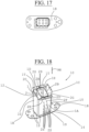
figure 17 is a view from below of a preferred embodiment of a metal fixing plate according to the present invention; -
figure 18 is a perspective view from above of the left side elevation of a preferred embodiment of a metal shock absorption element according to the present invention; -
figure 19 is a view from above of a preferred embodiment of a bumper structure for a motor vehicle according to the present invention; -
figure 20 is a view of the right side elevation of a detail of the bumper structure offig. 19 , sectioned according to the XX-XX line; -
figure 21 is a view of the right side elevation of a detail of the bumper structure offig. 19 , sectioned according to the XXI-XXI line; -
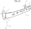
figure 22 is a perspective view from above in left side elevation of the bumper structure offig. 19 . - With reference to the figures, a metal
shock absorption element 10 is shown comprising afirst metal sheet 1 and asecond metal sheet 2, wherein saidfirst metal sheet 1 is shaped in the form of a longitudinally open metal profile and having a substantially "C"-shaped cross-section, and wherein saidsecond metal sheet 2 is shaped in the form of a longitudinally open metal section and having a substantially "C"-shaped cross-section. - According to the invention, said
first metal sheet 1 is folded in the shape of a longitudinally open metal profile, in particular having at least five metal walls, and preferably having an open and substantially rectangular cross-section. - According to the invention, said
second metal sheet 2 is folded in the shape of a longitudinally open metal profile, in particular having at least five metal walls, and preferably having an open and substantially rectangular cross-section. - Preferably, said
first metal sheet 1 comprises a plurality of particularly longitudinal and preferably high-resistance folds, which connect a plurality of adjacent metal walls of the same, and wherein each fold defines an angle or a roughened corner of saidfirst metal sheet 1 shaped in the form of said first longitudinally open metal profile. - Preferably, said
second metal sheet 2 comprises a plurality of particularly longitudinal and preferably high-resistance folds, which connect a plurality of adjacent metal walls of the same, and wherein each fold defines an angle or a roughened corner of saidsecond metal sheet 2 shaped in the form of said second longitudinally open metal profile. - According to the present invention, said
second metal sheet 2 is inserted within a firstlongitudinal channel 1G of saidfirst metal sheet 1, moreover saidsecond metal sheet 2 is made integral in one piece with saidfirst metal sheet 1, in particular in a plurality ofpoints 2S and preferably along at least two opposite sides to each other, to create a metal honeycomb structure having a closed cross-section and having a plurality of metal channels, in particular having at least three metal channels. - According to the invention, said metal honeycomb structure comprises a plurality of metal channels, at least three metal channels, which extend along said direction of
development 98 which is parallel or inclined with respect to alongitudinal direction 95, in particular which is perpendicular to atransverse direction 96, which in turn is perpendicular to avertical direction 97 which is also perpendicular to said longitudinal direction. - According to the invention, said
second metal sheet 2 comprises a secondlongitudinal channel 2G and is inserted within said firstlongitudinal channel 1G of saidfirst metal sheet 1 in a substantially central position for dividing said firstlongitudinal channel 1G into a plurality of metal channels and preferably into at least three longitudinal metal channels for creating said metal honeycomb structure. - Moreover, said
second metal sheet 2 is preferably inserted within said firstlongitudinal channel 1G of saidfirst metal sheet 1 such that a first side opening 1F of saidfirst metal sheet 1 is opposite a second side opening 2F of saidsecond metal sheet 2, in particular with respect to a central point of said cross-section, to create a metal honeycomb structure having a closed and preferably symmetrical cross-section. - According to the invention, this makes it possible to have a metal
shock absorption element 10 having a metal honeycomb structure in a single piece having a closed and preferably symmetrical cross-section with respect to a central point. - Advantageously, this makes it possible to have reduced weight and increased stability during a shock in order to absorb greater energy at the same weight.
- Preferably, said
first metal sheet 1 has external transverse dimensions which are slightly greater than an external transverse dimension of saidsecond metal sheet 2 to allow the insertion of saidsecond metal sheet 2 inside saidfirst metal sheet 1 such that saidsecond metal sheet 2 has the walls of two opposite sides in contact with the walls of two opposite sides of saidfirst metal sheet 1, in other words saidfirst metal sheet 1 has external transverse dimensions which are substantially equal to the sum of twice the thickness of the walls of saidfirst metal sheet 1 added to the external transverse dimensions of saidsecond metal sheet 2. - According to the invention, said
first metal sheet 1 comprises afirst wall 1A, asecond wall 1B and athird wall 1C which extend perpendicularly from saidfirst wall 1A, and further comprises afourth wall 1D which extends perpendicularly to saidsecond wall 1B, and furthermore it comprises afifth wall 1E which extends perpendicularly to saidthird wall 1C, and wherein saidfourth wall 1D and saidfifth wall 1E are parallel to saidfirst wall 1A for creating said open, substantially "C"-shaped cross-section, and wherein saidfourth wall 1D and saidfifth wall 1E define aside opening 1F having in particular a transverse width of 10 mm and in particular of 4 mm. - Preferably said
first metal sheet 1 is a folded metal sheet having a tubular shape with a substantially rectangular cross-section open longitudinally and transversely. - Preferably each wall of said plurality of walls (1A, 1B, 1C, 1D, 1E) has a flat, smooth surface, in particular without protuberances or reliefs or any wavy patterns.
- According to the invention, said
second metal sheet 2 comprises afirst wall 2A, asecond wall 2B and athird wall 2C which extend perpendicularly from saidfirst wall 2A, and further comprises afourth wall 2D which extends perpendicularly to saidsecond wall 2B, and furthermore it comprises afifth wall 2E which extends perpendicularly to saidthird wall 2C, and wherein saidfourth wall 2D and saidfifth wall 2E are parallel to saidfirst wall 2A for creating said open, substantially "C"-shaped cross-section, and wherein saidfourth wall 2D and saidfifth wall 2E define aside opening 2F having in particular a transverse width of 10 mm and in particular of 4 mm. - Preferably said
second metal sheet 2 is a folded metal sheet having a tubular shape with a substantially rectangular cross-section open longitudinally and transversely. - Preferably each wall of said plurality of walls (2A, 2B, 2C, 2D, 2E) has a flat, smooth surface, in particular without protuberances or reliefs or any wavy patterns.
- Preferably said
first wall 1A of saidfirst metal sheet 1 is coupled to said fourth 2D and saidfifth wall 2E of saidsecond metal sheet 2, moreover preferably saidfirst wall 2A of saidsecond metal sheet 2 is coupled to saidfourth wall 1D and saidfifth wall 1E of saidfirst metal sheet 1. - According to the invention, said
second metal sheet 2 is made integral in one piece with saidfirst metal sheet 1, in particular in a plurality ofpoints 2S which are preferably distributed along at least two opposite walls of saidfirst metal sheet 1 and of saidsecond metal sheet 2 which face each other, and in particular are mutually joined, and wherein preferably said plurality ofpoints 2S is a plurality of welding points in particular without the addition of material, i.e. by casting the material of said first metal sheet and saidsecond metal sheet 2 in a plurality of points. - Preferably said plurality of points comprises at least one matrix of
welding points 2S which are preferably made inside said fourth 2D and saidfifth wall 2E of saidsecond metal sheet 2 in order to join the same in a single piece with saidfirst wall 1A, and furthermore, which are made inside saidfirst wall 2A in order to join the same in a single piece with saidfourth wall 1D and saidfifth wall 1E. - Preferably, said metal
shock absorption element 10 comprises a firstopen front end 12 and a secondrear end 14, wherein said firstopen front end 12 is inclined with respect to atransverse direction 96 and in particular is not perpendicular to a direction ofextension 98 of said metal honeycomb structure. - Preferably, said metal
shock absorption element 10 comprises a plurality of notches which are made at said firstopen front end 12 and in particular which are made on saidfirst metal sheet 1 which in particular is more external with respect to saidsecond metal sheet 2. - According to the invention, said
first metal sheet 1 comprises a plurality ofmetal fixing walls 1T which extend from said plurality of walls (1A, 2A, 3A, 4A, 5A) at said firstopen front end 12, to fix said shock absorption element to ametal crosspiece 60. - Alternatively, said plurality of
metal fixing walls 1T can be made on saidsecond metal sheet 2 at said firstopen front end 12. - According to the invention at least a part of said plurality of
metal fixing walls 1T is inclined with respect to a direction ofextension 98 of said metal honeycomb structure to favour the start of a plurality of planned folds of said metalshock absorption element 10, starting from said first openfront end 12. - Preferably said plurality of
metal fixing walls 1T are made in a single piece with saidmetal sheet 1. - Preferably said metal
shock absorption element 10 comprises ametal fixing plate 18 which is made integral, in particular which is welded or brazed, to saidfirst metal sheet 1 at said secondrear end 14 in particular for fixing said secondrear end 14 of said metalshock absorption element 10 to a chassis of a motor vehicle and in particular to a longitudinal beam of a vehicle. - In particular, said
metal fixing plate 18 is welded and preferably brazed to said plurality of walls (1A, 1B, 1C, 1D, 1E) of saidfirst metal sheet 1 in a plurality ofzones 1S. - Preferably, said
first metal sheet 1 and said at least onesecond metal sheet 2 have a thickness lower than 2 mm and in particular lower than 1.6 mm. - Preferably, said
first metal sheet 1 has a thickness lower than 2 mm and in particular comprised between 0.8 mm and 1.4 mm and even more particularly comprised between 1 mm and 1.2 mm. - Preferably, said
second metal sheet 2 has a thickness lower than 2 mm and in particular comprised between 0.8 mm and 1.6 mm and even more particularly comprised between 0.6 mm and 1.4 mm. - Moreover, preferably said
first metal sheet 1 and saidsecond metal sheet 2 are made of steel, in particular a steel having two crystalline phases, a first martensitic phase and a second ferritic phase, preferably a type of steel having an elongation at break of substantially 7%, such as in particular a two-phase steel, for example known with the commercial code DP 1000, in particular a carbon steel having in particular the following composition: - a maximum percentage of Carbon comprised between 0.14% - 0.23% C,
- a maximum percentage of Silicon of 0.80% Si,
- a maximum percentage of Manganese comprised between 2.0% - 2.50% Mn,
- preferably a maximum percentage of Phosphorus of 0.080% P,
- preferably a maximum percentage of Sulphur of 0.015% S,
- preferably a maximum percentage of Aluminium of 2.00% Al,
- preferably a maximum percentage of Chromium and Molybdenum of 1.00% Cr+Mo,
- preferably a maximum percentage of Niobium and Titanium of 0.15% Nb+Ti,
- preferably a maximum percentage of Vanadium of 0.20% V,
- preferably a maximum percentage of Boron of 0.005% B.
- With reference to
figure 2 , preferably saidfirst metal sheet 1 comprises at least one first sheared side 1Z having a profile shaped for making a plurality of metal fixing elements and preferably for making a plurality of notches. - Furthermore, preferably said at least one first sheared side 1Z has a profile shaped to allow the creation of a first open
front end 12 which is inclined with respect to saidtransverse direction 96 and in particular which is not perpendicular to a direction ofextension 98 of said metal honeycomb structure, advantageously to allow the start of a plurality of planned folds starting from said first openfront end 12. - This advantageously makes it possible to avoid making a plurality of metal fixing elements through laser cutting, advantageously reducing the overall cost of said metal
shock absorption element 10. - Moreover, this advantageously makes it possible to create a plurality of notches to avoid the deformation of a plurality of walls of said
first metal sheet 1 following the folding of saidsecond metal sheet 1. - With reference to
figure 4 , preferably saidsecond metal sheet 2 comprises at least one second sheared side 2Z having a profile shaped for making a first openfront end 12 which is inclined with respect to atransverse direction 96 and in particular for making a plurality of notches and/or preferably for making a plurality of metal fixing elements. - Furthermore, preferably said at least one second sheared side 2Z has a profile shaped to allow the creation of a first open
front end 12 which is inclined with respect to saidtransverse direction 96 and in particular which is not perpendicular to a direction ofextension 98 of said metal honeycomb structure, advantageously to allow the start of a plurality of planned folds starting from said first openfront end 12. - This advantageously makes it possible to avoid making a series of cuts with a laser, advantageously reducing the overall cost of said metal
shock absorption element 10 reducing the overall cost of said metalshock absorption element 10. - According to another aspect of the present invention, a production method is provided for a metal
shock absorption element 10 as defined by appended claims 1-11 having an alveolar structure which comprises at least two metalshock absorption elements 10, in particular having one or more previously described characteristics, starting from afirst metal sheet 1, in particular substantially flat and preferably substantially rectangular, and from asecond metal sheet 2, in particular substantially flat and preferably substantially rectangular, wherein said method comprises the following steps: A) bending said first preferably shaped metal sheet 1 a plurality of times to obtain a first longitudinally open metal profile having a substantially "C"-shaped cross-section and in particular having an open rectangular shape, and further comprising a step of B) folding said preferably shaped second metal sheet 2 a plurality of times to obtain a second longitudinally open metal profile having a substantially "C"shaped cross-section, and in particular having an open rectangular shape. - Said step A) comprises a step A1) of creating a plurality of metal walls, at least five metal walls (1A, 1B, 1C, 1D, 1E).
- Said step A1) envisages the creation of a
first wall 1A, asecond wall 1B and athird wall 1C which extend perpendicularly from saidfirst wall 1A, and a furtherfourth wall 1D which extends perpendicularly to saidsecond wall 1B, and furthermore afifth wall 1E which extends perpendicularly to saidthird wall 1C, and wherein saidfourth wall 1D and saidfifth wall 1E are parallel to saidfirst wall 1A, in particular for creating said open substantially "C"-shaped cross-section, and wherein said fourth wall and said fifth wall define aside opening 1F having in particular a transverse width of 10 mm and in particular of 4 mm. - Said step B) comprises a step B1) of creating a plurality of metal walls, in particular at least five metal walls (2A, 2B, 2C, 2D, 2E).
- Said step A1) envisages the creation of a
first wall 2A, asecond wall 2B and athird wall 2C which extend perpendicularly from saidfirst wall 2A, and a furtherfourth wall 2D which extends perpendicularly to saidsecond wall 2B, and furthermore afifth wall 2E which extends perpendicularly to saidthird wall 2C, and wherein saidfourth wall 2D and saidfifth wall 2E are parallel to saidfirst wall 2A, for creating said open substantially "C"-shaped cross-section, and wherein said fourth wall and said fifth wall define aside opening 2F having in particular a transverse width of 10 mm and in particular of 4 mm. - Preferably said step A) comprises a step A2) of creating a plurality of particularly longitudinal and preferably high-strength folds which connect a plurality of adjacent metal walls (1A, 1B, 1C, 1D, 1E), and wherein each fold defines an angle or a roughened corner of said first longitudinally open metal profile.
- Preferably said step B) comprises a step B2) of creating a plurality of particularly longitudinal and preferably high-resistance folds which connect a plurality of adjacent metal walls (2A, 2B, 2C, 2D, 2E), and wherein each fold defines an angle or a roughened corner of said second longitudinally open metal profile.
- Said method comprises a step C) of longitudinally inserting said second metal profile inside said first metal profile, in particular in a first
longitudinal channel 1G of said first metal profile, in particular with a cross-section of said second metal profile rotated 180° with respect to a cross-section of said second metal profile, and in particular comprising a step C1) of positioning afirst side opening 1F of said first metal profile and a second side opening 2F of said second metal profile respectively in diametrically opposed positions with respect to a central point of said cross-section to create a metal honeycomb structure having a closed and preferably symmetrical cross-section. - Preferably, said method further comprises a step C2) of superimposing at least two metal walls of said first metal profile and said second metal profile, in particular for each of the two opposite sides, in particular coupling at least two opposite walls to each other of said
first metal sheet 1 and saidsecond metal sheet 2, which face each other. - Preferably, said method comprises a step C3) of dividing a first
longitudinal channel 1G of said first metal profile in a plurality of metal channels and preferably in at least three longitudinal metal channels and in particular a step C4) of inserting said second metal profile centrally to said firstlongitudinal channel 1G of said first metal profile. - According to the invention, said method comprises a step D) of making said
second metal sheet 2 integral to saidfirst metal sheet 1 in a single piece, in particular in a plurality ofpoints 2S which are preferably distributed along at least two opposite walls of saidfirst metal sheet 1 and saidsecond metal sheet 2 which face each other, and in particular which mutually join together to produce a metal honeycomb structure having a closed cross-section and having a plurality of metal channels, in particular having at least three metal channels. - Advantageously, this makes it possible to have a metal
shock absorption element 10 having a metal honeycomb structure in a single piece having a closed and preferably symmetrical cross-section with respect to a central point. - Advantageously, this makes it possible to have reduced weight and increased stability during a shock in order to absorb greater energy at the same weight.
- Preferably, said step D) comprises a step D1) of welding along a plurality of longitudinal directions in a plurality of
points 2S said first metal profile to said second metal profile, creating a metalshock absorption element 10 in one piece and having a metal honeycomb structure comprising at least three longitudinal channels. - Preferably, said step D1) comprises a step D2) of welding at points, in particular through CO2, said second metal profile to said first metal profile, making a plurality of welds at
points 2S in particular on walls of the same which overlap, and preferably along at least two opposite sides, in particular without the addition of material, and in particular comprising a step D3) of casting said first metal profile to said second metal profile in a plurality ofpoints 2S. - Preferably said step D1) comprises a step D3) of internally welding said first metal profile to said second metal profile, making a plurality of welds at
points 2S. - Preferably, said step D1) comprises a step D4) of creating a matrix of
welding points 2S in particular inside saidsecond metal sheet 2 for joining the same in a single piece with saidfirst metal sheet 1. - Preferably said step D1) comprises a step D5) of welding in a plurality of
points 2S afourth wall 2D and afifth wall 2E of saidsecond metal sheet 2 with afirst wall 1A of saidfirst metal sheet 1 to join the same in one single piece, and further welding in a plurality ofpoints 2S afirst wall 2A of saidsecond metal sheet 2 with afourth wall 1D and afifth wall 1E of saidfirst metal sheet 1 to join them in one single piece. - Preferably, said method comprises a step E) of keeping a plurality of walls of said first metal profile and said second metal profile flat and smooth.
- Preferably, said method comprises a step H1) of shaping said
first metal sheet 1 to obtain a first shapedmetal sheet 1 having along a first openproximal end 12 at least two metal fixing tabs and at least two diagonal lines; wherein said phase H1 is carried out before said phase A), advantageously to reduce production costs, and further comprises a step L1) of shaping saidsecond metal sheet 2 to obtain a second shapedmetal sheet 2 having along a first openproximal end 12 at least two diagonal lines; wherein said phase L1) is carried out before said phase B), advantageously to reduce production costs. - Preferably said step H1) comprises a step H2) of shearing said
first metal sheet 1, simultaneously producing at least one metal fixing element for fixing ametal crosspiece 60 and at least one notch preferably adjacent to at least one metal fixing element. - According to the invention, said step H1) comprises a step H2) of shearing said
first metal sheet 1, simultaneously producing a plurality ofmetal fixing walls 1T for fixing ametal crosspiece 60 and a plurality of notches, each of which is preferably adjacent to at least onemetal fixing wall 1T. - This advantageously makes it possible to avoid making a plurality of metal fixing elements or metal walls through laser cutting, advantageously reducing the overall cost of said metal
shock absorption element 10. - Moreover, this advantageously makes it possible to create a plurality of notches to avoid the deformation of a plurality of walls of said
first metal sheet 1 following the folding of saidsecond metal sheet 2. - Preferably, said step L1) comprises a step L2) of shearing said
second metal sheet 2, simultaneously creating a plurality of diagonal lines to form a first openfront end 12 which is inclined with respect to thetransverse direction 96, and in particular providing a plurality of notches and /or preferably by making a plurality of metal fixing elements for saidmetal crosspiece 60. - This advantageously makes it possible to avoid making a plurality of metal fixing elements through laser cutting, advantageously reducing the overall cost of said metal
shock absorption element 10. - Moreover, this advantageously makes it possible to create a plurality of notches to avoid the deformation of a plurality of walls of said
second metal sheet 2 following the folding of saidsecond metal sheet 2. - Preferably, said first metal profile comprises at least one notch made at two adjacent faces at said first open
proximal end 12. - In particular, said at least one notch is positioned at a corresponding tab or fixing flange for a
metal crosspiece 60. - According to another aspect of the present invention, at least one mould and/or equipment for creating at least one metal
shock absorption element 10 having one or more of the previously described characteristics or according to one or more of the previously described embodiments is provided. - According to another aspect of the present invention, a bumper structure is provided for a motor vehicle which comprises at least two metal
shock absorption elements 10 having one or more of the previously described characteristics or according to one or more of the previously described embodiments, and further comprising ametal crosspiece 60 having a substantially rectangular cross-section and formed by two "C"-shaped metal profiles welded to each other in a manner, and a polymeric outer bumper casing, not shown in the figures, having only an aesthetic function to cover saidmetal crosspiece 60 and said at least two polymericshock absorption elements 10. - Preferably said
metal crosspiece 60 comprises two substantially flat base portions, each of which is fixed to or made integral with a corresponding first openfront end 12 of each metal shock absorption element, and in particular is made integral in one single piece with a plurality ofmetal fixing walls 1T, advantageously avoiding the direct fixing of saidmetal crosspiece 60. - Preferably said
metal crosspiece 60 comprises at each metalshock absorption element 10 one comprising a metal element having a substantially "Ω"shaped cross-section which is welded or in any case made integral within said metal crosspiece to further stiffen in a localised zone saidmetal crosspiece 60, thereby reducing the weight and the overall cost, which would be impossible with extruded metal profiles, for example of aluminium, which have the same section along their entire length. - Advantageously, in this way it is possible to create a metal bumper structure in one single piece with high shock absorption characteristics accompanied by a reduced weight and cost.
- Advantageously, this gives said at least one polymeric
shock absorption element 10 greater stability, and therefore also gives said bumper structure greater stability. - Preferably said
metal crosspiece 60 is made of steel, in particular a type of steel having two crystalline phases, a first martensitic phase and a second ferritic phase, preferably a type of steel having an elongation at break of substantially 7%, such as in particular a two-phase steel, for example known with the commercial code DP 1000, in particular a carbon steel having in particular the composition described above. - According to another aspect of the present invention, at least one mould and one apparatus are provided for making a
crosspiece 60 and for a bumper structure having one or more of the previously described characteristics or according to one or more of the previously described embodiments. - According to another aspect of the present invention, an apparatus is provided comprising a plurality of moulds for making a bumper structure comprising a
crosspiece 60 and a plurality of metal shock absorption elements having one or more of the previously described characteristics or according to one or more of the previously described embodiments. - According to another aspect of the present invention, a chassis for a motor vehicle is provided comprising at least one metal
shock absorption element 10 having one or more of the previously described characteristics or according to one or more of the previously described embodiments and preferably comprising ametal crosspiece 60 having one or more of the previously described characteristics or according to one or more of the previously described embodiments. - According to another aspect of the present invention, a motor vehicle is provided comprising a metal
shock absorption element 10 having one or more of the previously described characteristics or according to one or more of the previously described embodiments, and in particular comprising a bumper structure, preferably front or rear, having one or more of the previously described characteristics or according to one or more of the previously described embodiments. - Moreover, said motor vehicle preferably comprises a chassis, an engine connected to said chassis, at least three wheels, in particular at least four wheels, of which at least one front wheel, and a passenger compartment.
- It has thus been seen that a metal shock absorption element for a motor vehicle and a relative production method according to the present invention accomplish the previously highlighted objects.
- The metal shock absorption element for a motor vehicle and the relative production method of the present invention thus conceived are susceptible to numerous modifications and variations, all of which fall under the same inventive concept, as defined by the appended set of claims.
- Furthermore, in practice the materials used, as well as their dimensions and components, can be of any type according to the technical requirements.
Claims (13)
- A metal shock absorption element (10) comprising a first metal sheet (1) and a second metal sheet (2), wherein said first metal sheet (1) is shaped in the form of a longitudinally open metal profile and having a substantially "C"-shaped cross-section and wherein said second metal plate (2) is shaped in the form of a longitudinally open metal profile and having a substantially "C"-shaped cross section, said second metal sheet (2) is inserted in a first longitudinal channel (1G) of said first metal sheet (1), moreover said second metal sheet (2) is made integral in one single piece with said first metal sheet (1) in a plurality of points (2S) to create a metal honeycomb structure having a closed cross-section and having a plurality of metal channels,said first metal sheet (1) comprises a first wall (1A), a second wall (1B) and a third wall (1C) which extend perpendicularly from said first wall (1A), and further comprises a fourth wall (1D) which extends perpendicularly to said second wall (1B), and further comprises a fifth wall (1E) which extends perpendicularly to said third wall (1C), and wherein said fourth wall (1D) and said fifth wall (1E) are parallel to said first wall (1A) to create said open, substantially "C"-shaped cross-section, and wherein said fourth wall and said fifth wall define a side opening (1F) having in particular a transverse width of 10 mm and in particular of 4 mm, furthermore said second metal sheet (2) comprises a first wall (2A), a second wall (2B) and a third wall (2C) which extend perpendicularly from said first wall (2A), and further comprises a fourth wall (2D) which extends perpendicularly to said second wall (2B), and further comprises a fifth wall (2E) which extends perpendicularly to said third wall (2C), and wherein said fourth wall (2D) and said fifth wall (2E) are parallel to said first wall (2A) to create said open and substantially "C"-shaped cross-section, and wherein said fourth wall and said fifth wall define a side opening (2F) having in particular a transverse width of 10 mm and in particular of 4 mm, characterised in thatsaid first metal sheet (1) comprises a plurality of metal fixing walls (1T) which extend from said plurality of walls (1A, 2A, 3A, 4A, 5A) at said first open front end (12), to fix said shock absorption element to a metal crosspiece (60),at least a part of said plurality of metal fixing walls (1T) are inclined with respect to a direction of extension (98) of said metal honeycomb structure to favour the start of a plurality of programmed folds of said metal shock absorption element (10), starting from said first open front end (12).
- The metal shock absorption element (10) according to claim 1, characterised in that said second metal sheet (2) is inserted within said first longitudinal channel (1G) of said first metal sheet (1) such that a first side opening (1F) of said first metal sheet (1) is opposite a second side opening (2F) of said second metal sheet (2), in particular with respect to a central point of said cross-section, to create a metal honeycomb structure having a closed and preferably symmetrical cross-section.
- The metal shock absorption element (10) according to claim 1 or 2, characterised in that said plurality of points (2S) is distributed along at least two opposite walls of said first metal sheet (1) and said second metal sheet (2) facing each other and wherein said plurality of points (2S) is a plurality of welding points.
- The metal shock absorption element (10) according to any one of claims 1 to 3, characterised in that said metal shock absorption element (10) comprises a first front end (12) and a second rear end (14), wherein said first open front end (12) is inclined with respect to a transverse direction (96) and in particular which is not perpendicular to a direction of extension (98) of said metal honeycomb structure.
- The metal shock absorption element (10) according to claim 4, characterised in that it comprises a plurality of notches which are made at said first open front end (12) and in particular which are made on said first metal sheet (1) which in particular is more external with respect to said second metal sheet (2).
- The metal shock absorption element (10) according to any one of claims 1 to 5, characterised in that it comprises a metal fixing plate (18) which is made integral, in particular which is welded or brazed, with said first metal sheet (1) at a second rear end (14) for fixing said second rear end (14) of said metal shock absorption element (10) to a chassis of a motor vehicle and in particular to a longitudinal beam of a vehicle.
- The metal shock absorption element (10) according to any of claims 1 to 6, characterised in that said first metal sheet (1) and said second metal sheet (2) are made of steel, in particular steel having two crystalline phases, a first martensitic phase and a second ferritic phase, preferably a type of steel having an elongation at break of substantially 7%, such as in particular a two-phase steel, for example known with the commercial code DP 1000.
- The metal shock absorption element (10) according to any one of claims 1 to 7, characterised in that said first metal sheet (1) comprises at least one first sheared side (1Z) having a profile shaped to create a plurality of metal fixing elements and preferably to create a plurality of notches, furthermore preferably said at least one sheared first side (1Z) has a profile shaped to allow the creation of a first open front end (12) which is inclined with respect to a transverse direction (96) and in particular which is not perpendicular to a direction of development (98) of said metal honeycomb structure, advantageously to allow the start of a plurality of planned folds starting from said first open front end (12), furthermore preferably said second metal sheet (2) comprises at least a second sheared side (2Z) having a profile shaped to create a first open front end (12) which is inclined with respect to said transverse direction (96) and in particular to create a plurality of notches and/or preferably to create a plurality of metal fixing elements.
- A bumper structure for a motor vehicle which comprises at least two metal shock absorption elements (10) according to at least one of claims 1 to 8, and further comprising a metal crosspiece (60) having an essentially rectangular cross-section and formed by two "C"-shaped metal profiles welded together, and a bumper with polymeric outer casing, not shown in the figures, having only an aesthetic function to cover said metal crosspiece (60) and said at least two polymeric shock absorption elements (10), furthermore preferably said metal crosspiece (60) comprises two substantially flat base portions, each of which is fixed to or made integral with a corresponding first open front end (12) of each metal shock absorption element, and in particular made integral in one piece with a plurality of metal fixing walls (1T), advantageously avoiding the direct fixing of said metal crosspiece (60), furthermore preferably said metal crosspiece (60) comprises at each metal shock absorption element (10), one comprising a metal element having a substantially "Ω"-shaped cross-section which is welded or otherwise made integral inside said metal crosspiece to further stiffen said metal crosspiece (60) in a localized zone.
- A motor vehicle comprising at least one metal shock absorption element (10) according to any one of claims 1 to 8, and in particular comprising a bumper structure according to claim 9.
- An apparatus comprising a plurality of moulds for making a bumper structure according to claim 9.
- A production method for a metal shock absorption element (10) according to one of claims 1-11 having a honeycomb structure, starting from a first metal sheet (1), and a second metal sheet (2), characterised in that it comprises the following steps: A) folding said first metal sheet (1) preferably shaped a plurality of times, obtaining a first longitudinally open metal profile having a substantially "C"-shaped cross section and in particular having an open rectangular shape; B) folding said second metal sheet (2) preferably shaped a plurality of times, obtaining a second longitudinally open metal profile having a substantially "C"-shaped cross-section and in particular having an open rectangular shape; C) inserting longitudinally said second metal profile inside said first metal profile, in particular within a first longitudinal channel (1G) of said first metal profile, in particular with a cross-section of said second metal profile rotated 180° with respect to a cross-section of said second metal profile; D) making integral in one piece said second metal sheet (2) with said first metal sheet (1) in particular in a plurality of points (2S), which are preferably distributed along at least two opposite walls of said first metal sheet (1) and said second metal sheet (2) which face each other, and are in particular coupled to each other to produce a metal honeycomb structure having a closed cross-section and having a plurality of metal channels, in particular having at least three metal channels,said method comprising comprises a step H1) of shaping said first metal sheet (1) to obtain a first shaped metal sheet (1) having along a first proximal end (12) at least two metal fixing tabs and at least two diagonal lines; wherein said step H1 is carried out before said step A), advantageously to reduce production costs, and further comprises a step L1) of shaping said second metal sheet (2) obtaining a second shaped metal sheet (2) having along a first proximal end (12) at least two diagonal lines; wherein said phase L1) is carried out before said phase B), advantageously to reduce production costs.characterised in that said step H1) comprises a step H2) of shearing said first metal sheet (1) while simultaneously creating at least one metal fixing element for fixing a metal crosspiece (60) and at least one notch, preferably adjacent to at least one metal fixing element, and wherein said step L1) comprises a step L2) of shearing said second metal sheet (2) while simultaneously creating a plurality of diagonal lines to form a first open front end (12) which is inclined with respect to the transverse direction (96), and a plurality of notches and/or preferably creating a plurality of metal fixing elements for said metal crosspiece (60).
- The method according to claim 12, characterised in that said step D) comprises a step D1) of welding along a plurality of longitudinal directions in a plurality of points 2S said first metal profile to said second metal profile, creating a metal shock absorption element 10 in one piece and having a metal honeycomb structure comprising at least three longitudinal channels.
Applications Claiming Priority (2)
| Application Number | Priority Date | Filing Date | Title |
|---|---|---|---|
| IT102017000111991A IT201700111991A1 (en) | 2017-10-05 | 2017-10-05 | Metal shock absorbing element for a motor vehicle and its production method |
| PCT/IB2018/057750 WO2019069281A1 (en) | 2017-10-05 | 2018-10-05 | Metal shock absorption element for a motor vehicle and related production method |
Publications (2)
| Publication Number | Publication Date |
|---|---|
| EP3673186A1 EP3673186A1 (en) | 2020-07-01 |
| EP3673186B1 true EP3673186B1 (en) | 2023-03-15 |
Family
ID=61526879
Family Applications (1)
| Application Number | Title | Priority Date | Filing Date |
|---|---|---|---|
| EP18804385.5A Active EP3673186B1 (en) | 2017-10-05 | 2018-10-05 | Metal shock absorption element for a motor vehicle and related production method |
Country Status (6)
| Country | Link |
|---|---|
| US (1) | US11691580B2 (en) |
| EP (1) | EP3673186B1 (en) |
| CN (1) | CN111183298B (en) |
| IT (1) | IT201700111991A1 (en) |
| MA (1) | MA49958A (en) |
| WO (1) | WO2019069281A1 (en) |
Families Citing this family (2)
| Publication number | Priority date | Publication date | Assignee | Title |
|---|---|---|---|---|
| US11034315B2 (en) * | 2018-04-17 | 2021-06-15 | Tesla, Inc. | Advanced thin-walled structures for enhanced crash performance |
| EP4737276A2 (en) * | 2019-04-02 | 2026-05-06 | Zephyros, Inc. | Reinforcement structure |
Family Cites Families (33)
| Publication number | Priority date | Publication date | Assignee | Title |
|---|---|---|---|---|
| SE383128B (en) * | 1974-07-04 | 1976-03-01 | Saab Scania Ab | CELL BLOCK FOR SHOCK RECORDING |
| US4661030A (en) | 1983-11-28 | 1987-04-28 | General Motors Corporation | Adjustable fastener for bumper bar |
| CN1073402A (en) * | 1991-11-06 | 1993-06-23 | 肯塞特分析公司 | The elastic energy absorption plant that is used for vehicle bumper |
| DE10013527A1 (en) * | 2000-03-20 | 2001-10-11 | Benteler Werke Ag | Steel transverse bumper (fender) cross-bearer making process involves joining narrow strips into bonded element and deforming it by roll deforming process |
| DE10112424A1 (en) * | 2001-03-15 | 2002-09-26 | Daimler Chrysler Ag | Front of a motor vehicle comprises an air guiding part arranged below a bumper and interacting in the event of a front collision with the bumper covering and reinforcing this in a region positioned in front of the bumper |
| CN100351121C (en) | 2003-05-14 | 2007-11-28 | 京洛株式会社 | Shock absorber of car |
| US6923482B2 (en) * | 2003-06-27 | 2005-08-02 | Magna International Inc. | Multiple material bumper beam |
| US6971691B1 (en) * | 2004-06-25 | 2005-12-06 | Shape Corporation | Vehicle bumper beam |
| US7163243B2 (en) * | 2004-12-13 | 2007-01-16 | Netshape International, Llc | Bumper for pedestrian impact having thermoformed energy absorber |
| SE527962C2 (en) * | 2005-09-23 | 2006-07-25 | Gestamp Hardtech Ab | Vehicle bumper beam fixture is fixed in pair of crash boxes, upper and lower sides of each box forming fixture flaps |
| CN101346259A (en) * | 2005-12-27 | 2009-01-14 | 沙普公司 | Vehicle bumper beams made of metal and plastic |
| US20070257497A1 (en) * | 2005-12-27 | 2007-11-08 | Heatherington David W | Vehicle bumper beam constructed of metal and plastic |
| SE529533C2 (en) * | 2006-01-24 | 2007-09-04 | Gestamp Hardtech Ab | Car crash box |
| US7651155B2 (en) * | 2006-11-03 | 2010-01-26 | Gm Global Technology Operations, Inc. | Progressive energy absorber |
| JP5330674B2 (en) * | 2007-11-05 | 2013-10-30 | 豊田鉄工株式会社 | Crash box |
| US8210601B2 (en) * | 2008-09-18 | 2012-07-03 | Mazda Motor Corporation | Vehicle body structure |
| JP5329188B2 (en) * | 2008-11-21 | 2013-10-30 | 株式会社アステア | Bumper reinforcement |
| JP5337067B2 (en) * | 2010-02-02 | 2013-11-06 | 豊田鉄工株式会社 | Hook support device for towing vehicle |
| FR2978410B1 (en) * | 2011-07-29 | 2013-08-09 | Peugeot Citroen Automobiles Sa | LONGERON FOR AUTOMOTIVE VEHICLE OF OCTAGONAL CROSS SECTION AND VEHICLE EQUIPPED WITH SUCH LONGERONS. |
| WO2013106905A1 (en) | 2012-01-18 | 2013-07-25 | Magna International Inc. | Sinusoidal crush can assembly |
| WO2014097398A1 (en) * | 2012-12-18 | 2014-06-26 | トヨタ自動車株式会社 | Structure for end part of vehicle |
| KR101484227B1 (en) * | 2013-07-09 | 2015-01-21 | 현대자동차 주식회사 | Hybrid bumper beam for vehicles and manufacturing method thereof and bumper beam unit for vehicles using this |
| JP6018127B2 (en) * | 2014-06-13 | 2016-11-02 | アイシン高丘株式会社 | Body parts |
| JP6070656B2 (en) * | 2014-09-03 | 2017-02-01 | トヨタ自動車株式会社 | Shock absorption box for vehicles |
| JP2016052859A (en) * | 2014-09-04 | 2016-04-14 | 豊田鉄工株式会社 | Bumper beam for vehicle |
| WO2016089989A1 (en) * | 2014-12-05 | 2016-06-09 | Shape Corp. | Beam incorporating aluminum extrusion and long-fiber reinforced plastic |
| US9731671B2 (en) * | 2015-03-10 | 2017-08-15 | Honda Motor Co., Ltd. | Energy absorber and bumper structural body |
| US9522644B2 (en) * | 2015-04-13 | 2016-12-20 | Benteler Automobiltechnik Gmbh | Bumper arrangement for a motor vehicle |
| JP6215891B2 (en) * | 2015-10-15 | 2017-10-18 | 本田技研工業株式会社 | Body structure with shock absorbing member |
| DE102015117700A1 (en) * | 2015-10-16 | 2017-04-20 | Magna International Inc. | Cross member and method for producing a cross member |
| US10279842B2 (en) * | 2016-08-30 | 2019-05-07 | Ford Global Technologies, Llc | Twenty-eight-cornered strengthening member for vehicles |
| US10507776B2 (en) * | 2017-10-12 | 2019-12-17 | GM Global Technology Operations LLC | Fiber-reinforced composite bumper beam and crush members |
| US10518811B2 (en) * | 2018-01-18 | 2019-12-31 | Honda Motor Co., Ltd. | Front side frame member for a vehicle front frame assembly |
-
2017
- 2017-10-05 IT IT102017000111991A patent/IT201700111991A1/en unknown
-
2018
- 2018-10-05 WO PCT/IB2018/057750 patent/WO2019069281A1/en not_active Ceased
- 2018-10-05 EP EP18804385.5A patent/EP3673186B1/en active Active
- 2018-10-05 MA MA049958A patent/MA49958A/en unknown
- 2018-10-05 CN CN201880064543.6A patent/CN111183298B/en active Active
- 2018-10-05 US US16/647,762 patent/US11691580B2/en active Active
Also Published As
| Publication number | Publication date |
|---|---|
| US11691580B2 (en) | 2023-07-04 |
| WO2019069281A1 (en) | 2019-04-11 |
| US20200262374A1 (en) | 2020-08-20 |
| MA49958A (en) | 2020-07-01 |
| EP3673186A1 (en) | 2020-07-01 |
| IT201700111991A1 (en) | 2019-04-05 |
| CN111183298B (en) | 2022-04-08 |
| CN111183298A (en) | 2020-05-19 |
Similar Documents
| Publication | Publication Date | Title |
|---|---|---|
| US7695052B2 (en) | Front rail having controlled thickness for energy absorption | |
| KR102427578B1 (en) | Reinforcement element for a vehicle, method for producing the same and door assembly | |
| US6591577B2 (en) | Automobile door reinforcing member | |
| CN114364577A (en) | Bumper cross-member for a motor vehicle | |
| EP4035951B1 (en) | Bumper assembly for a motor vehicle | |
| CN102529859A (en) | Bumper Cross Member For A Motor Vehicle, Reinforcement Component For A Bumper Cross Member And Method For Producing A Bumper Cross Member | |
| EP3386846B1 (en) | Vehicle front body structure and method for manufacturing thereof | |
| EP3673186B1 (en) | Metal shock absorption element for a motor vehicle and related production method | |
| EP2877388A1 (en) | B-pillar and method of manufacturing it | |
| EP4035952B1 (en) | Bumper assembly with additional support | |
| US10336271B2 (en) | Bumper beams, rocker panels and methods | |
| DE102009044417B4 (en) | Profile and method for its production | |
| CN110481639B (en) | Subframe for vehicle | |
| CN119789997A (en) | Front longitudinal beam of vehicle | |
| US6964096B2 (en) | Method of manufacturing a structural member and a member provided by such method | |
| JP2005528268A (en) | Y-shaped gusset structure for vehicle support frame | |
| CN119630577A (en) | Vehicle structure | |
| WO2006036065A1 (en) | Energy absorbing member and method for making an energy absorbing member | |
| JP7715739B2 (en) | Metallic structural component having a highly ductile patch and method of manufacturing the same | |
| WO2004113151A1 (en) | Support for a vehicle body | |
| CN110431063A (en) | Motor vehicle construction | |
| JP2025528326A (en) | Vehicle structure | |
| TWI893050B (en) | Expanded tube for a motor vehicle crash box with a working direction in a vehicle's longitudinal axis, the manufacturing method and the use as a crash box for it | |
| DE102012012901B4 (en) | Bumper arrangement for a motor vehicle | |
| WO2018119255A1 (en) | Cast bumper system and method of manufacturing same |
Legal Events
| Date | Code | Title | Description |
|---|---|---|---|
| STAA | Information on the status of an ep patent application or granted ep patent |
Free format text: STATUS: UNKNOWN |
|
| STAA | Information on the status of an ep patent application or granted ep patent |
Free format text: STATUS: THE INTERNATIONAL PUBLICATION HAS BEEN MADE |
|
| PUAI | Public reference made under article 153(3) epc to a published international application that has entered the european phase |
Free format text: ORIGINAL CODE: 0009012 |
|
| STAA | Information on the status of an ep patent application or granted ep patent |
Free format text: STATUS: REQUEST FOR EXAMINATION WAS MADE |
|
| 17P | Request for examination filed |
Effective date: 20200327 |
|
| AK | Designated contracting states |
Kind code of ref document: A1 Designated state(s): AL AT BE BG CH CY CZ DE DK EE ES FI FR GB GR HR HU IE IS IT LI LT LU LV MC MK MT NL NO PL PT RO RS SE SI SK SM TR |
|
| AX | Request for extension of the european patent |
Extension state: BA ME |
|
| DAX | Request for extension of the european patent (deleted) | ||
| RAV | Requested validation state of the european patent: fee paid |
Extension state: MA Effective date: 20200327 |
|
| STAA | Information on the status of an ep patent application or granted ep patent |
Free format text: STATUS: EXAMINATION IS IN PROGRESS |
|
| 17Q | First examination report despatched |
Effective date: 20211013 |
|
| REG | Reference to a national code |
Ref country code: DE Ref legal event code: R079 Ref document number: 602018047279 Country of ref document: DE Free format text: PREVIOUS MAIN CLASS: F16F0007120000 Ipc: B60R0019030000 |
|
| RIC1 | Information provided on ipc code assigned before grant |
Ipc: B60R 19/34 20060101ALI20220530BHEP Ipc: F16F 7/12 20060101ALI20220530BHEP Ipc: B60R 19/03 20060101AFI20220530BHEP |
|
| GRAP | Despatch of communication of intention to grant a patent |
Free format text: ORIGINAL CODE: EPIDOSNIGR1 |
|
| STAA | Information on the status of an ep patent application or granted ep patent |
Free format text: STATUS: GRANT OF PATENT IS INTENDED |
|
| INTG | Intention to grant announced |
Effective date: 20221007 |
|
| GRAS | Grant fee paid |
Free format text: ORIGINAL CODE: EPIDOSNIGR3 |
|
| GRAA | (expected) grant |
Free format text: ORIGINAL CODE: 0009210 |
|
| STAA | Information on the status of an ep patent application or granted ep patent |
Free format text: STATUS: THE PATENT HAS BEEN GRANTED |
|
| AK | Designated contracting states |
Kind code of ref document: B1 Designated state(s): AL AT BE BG CH CY CZ DE DK EE ES FI FR GB GR HR HU IE IS IT LI LT LU LV MC MK MT NL NO PL PT RO RS SE SI SK SM TR |
|
| REG | Reference to a national code |
Ref country code: CH Ref legal event code: EP Ref country code: GB Ref legal event code: FG4D |
|
| REG | Reference to a national code |
Ref country code: DE Ref legal event code: R096 Ref document number: 602018047279 Country of ref document: DE |
|
| REG | Reference to a national code |
Ref country code: IE Ref legal event code: FG4D |
|
| REG | Reference to a national code |
Ref country code: AT Ref legal event code: REF Ref document number: 1553841 Country of ref document: AT Kind code of ref document: T Effective date: 20230415 |
|
| REG | Reference to a national code |
Ref country code: LT Ref legal event code: MG9D |
|
| P01 | Opt-out of the competence of the unified patent court (upc) registered |
Effective date: 20230601 |
|
| REG | Reference to a national code |
Ref country code: NL Ref legal event code: MP Effective date: 20230315 |
|
| PG25 | Lapsed in a contracting state [announced via postgrant information from national office to epo] |
Ref country code: RS Free format text: LAPSE BECAUSE OF FAILURE TO SUBMIT A TRANSLATION OF THE DESCRIPTION OR TO PAY THE FEE WITHIN THE PRESCRIBED TIME-LIMIT Effective date: 20230315 Ref country code: NO Free format text: LAPSE BECAUSE OF FAILURE TO SUBMIT A TRANSLATION OF THE DESCRIPTION OR TO PAY THE FEE WITHIN THE PRESCRIBED TIME-LIMIT Effective date: 20230615 Ref country code: LV Free format text: LAPSE BECAUSE OF FAILURE TO SUBMIT A TRANSLATION OF THE DESCRIPTION OR TO PAY THE FEE WITHIN THE PRESCRIBED TIME-LIMIT Effective date: 20230315 Ref country code: LT Free format text: LAPSE BECAUSE OF FAILURE TO SUBMIT A TRANSLATION OF THE DESCRIPTION OR TO PAY THE FEE WITHIN THE PRESCRIBED TIME-LIMIT Effective date: 20230315 Ref country code: HR Free format text: LAPSE BECAUSE OF FAILURE TO SUBMIT A TRANSLATION OF THE DESCRIPTION OR TO PAY THE FEE WITHIN THE PRESCRIBED TIME-LIMIT Effective date: 20230315 |
|
| REG | Reference to a national code |
Ref country code: AT Ref legal event code: MK05 Ref document number: 1553841 Country of ref document: AT Kind code of ref document: T Effective date: 20230315 |
|
| PG25 | Lapsed in a contracting state [announced via postgrant information from national office to epo] |
Ref country code: SE Free format text: LAPSE BECAUSE OF FAILURE TO SUBMIT A TRANSLATION OF THE DESCRIPTION OR TO PAY THE FEE WITHIN THE PRESCRIBED TIME-LIMIT Effective date: 20230315 Ref country code: NL Free format text: LAPSE BECAUSE OF FAILURE TO SUBMIT A TRANSLATION OF THE DESCRIPTION OR TO PAY THE FEE WITHIN THE PRESCRIBED TIME-LIMIT Effective date: 20230315 Ref country code: GR Free format text: LAPSE BECAUSE OF FAILURE TO SUBMIT A TRANSLATION OF THE DESCRIPTION OR TO PAY THE FEE WITHIN THE PRESCRIBED TIME-LIMIT Effective date: 20230616 Ref country code: FI Free format text: LAPSE BECAUSE OF FAILURE TO SUBMIT A TRANSLATION OF THE DESCRIPTION OR TO PAY THE FEE WITHIN THE PRESCRIBED TIME-LIMIT Effective date: 20230315 |
|
| PG25 | Lapsed in a contracting state [announced via postgrant information from national office to epo] |
Ref country code: SM Free format text: LAPSE BECAUSE OF FAILURE TO SUBMIT A TRANSLATION OF THE DESCRIPTION OR TO PAY THE FEE WITHIN THE PRESCRIBED TIME-LIMIT Effective date: 20230315 Ref country code: RO Free format text: LAPSE BECAUSE OF FAILURE TO SUBMIT A TRANSLATION OF THE DESCRIPTION OR TO PAY THE FEE WITHIN THE PRESCRIBED TIME-LIMIT Effective date: 20230315 Ref country code: PT Free format text: LAPSE BECAUSE OF FAILURE TO SUBMIT A TRANSLATION OF THE DESCRIPTION OR TO PAY THE FEE WITHIN THE PRESCRIBED TIME-LIMIT Effective date: 20230717 Ref country code: ES Free format text: LAPSE BECAUSE OF FAILURE TO SUBMIT A TRANSLATION OF THE DESCRIPTION OR TO PAY THE FEE WITHIN THE PRESCRIBED TIME-LIMIT Effective date: 20230315 Ref country code: EE Free format text: LAPSE BECAUSE OF FAILURE TO SUBMIT A TRANSLATION OF THE DESCRIPTION OR TO PAY THE FEE WITHIN THE PRESCRIBED TIME-LIMIT Effective date: 20230315 Ref country code: CZ Free format text: LAPSE BECAUSE OF FAILURE TO SUBMIT A TRANSLATION OF THE DESCRIPTION OR TO PAY THE FEE WITHIN THE PRESCRIBED TIME-LIMIT Effective date: 20230315 Ref country code: AT Free format text: LAPSE BECAUSE OF FAILURE TO SUBMIT A TRANSLATION OF THE DESCRIPTION OR TO PAY THE FEE WITHIN THE PRESCRIBED TIME-LIMIT Effective date: 20230315 |
|
| PG25 | Lapsed in a contracting state [announced via postgrant information from national office to epo] |
Ref country code: SK Free format text: LAPSE BECAUSE OF FAILURE TO SUBMIT A TRANSLATION OF THE DESCRIPTION OR TO PAY THE FEE WITHIN THE PRESCRIBED TIME-LIMIT Effective date: 20230315 Ref country code: PL Free format text: LAPSE BECAUSE OF FAILURE TO SUBMIT A TRANSLATION OF THE DESCRIPTION OR TO PAY THE FEE WITHIN THE PRESCRIBED TIME-LIMIT Effective date: 20230315 Ref country code: IS Free format text: LAPSE BECAUSE OF FAILURE TO SUBMIT A TRANSLATION OF THE DESCRIPTION OR TO PAY THE FEE WITHIN THE PRESCRIBED TIME-LIMIT Effective date: 20230715 |
|
| REG | Reference to a national code |
Ref country code: DE Ref legal event code: R097 Ref document number: 602018047279 Country of ref document: DE |
|
| PLBE | No opposition filed within time limit |
Free format text: ORIGINAL CODE: 0009261 |
|
| STAA | Information on the status of an ep patent application or granted ep patent |
Free format text: STATUS: NO OPPOSITION FILED WITHIN TIME LIMIT |
|
| PG25 | Lapsed in a contracting state [announced via postgrant information from national office to epo] |
Ref country code: SI Free format text: LAPSE BECAUSE OF FAILURE TO SUBMIT A TRANSLATION OF THE DESCRIPTION OR TO PAY THE FEE WITHIN THE PRESCRIBED TIME-LIMIT Effective date: 20230315 Ref country code: DK Free format text: LAPSE BECAUSE OF FAILURE TO SUBMIT A TRANSLATION OF THE DESCRIPTION OR TO PAY THE FEE WITHIN THE PRESCRIBED TIME-LIMIT Effective date: 20230315 |
|
| 26N | No opposition filed |
Effective date: 20231218 |
|
| PG25 | Lapsed in a contracting state [announced via postgrant information from national office to epo] |
Ref country code: MC Free format text: LAPSE BECAUSE OF FAILURE TO SUBMIT A TRANSLATION OF THE DESCRIPTION OR TO PAY THE FEE WITHIN THE PRESCRIBED TIME-LIMIT Effective date: 20230315 |
|
| REG | Reference to a national code |
Ref country code: CH Ref legal event code: PL |
|
| REG | Reference to a national code |
Ref country code: BE Ref legal event code: MM Effective date: 20231031 |
|
| PG25 | Lapsed in a contracting state [announced via postgrant information from national office to epo] |
Ref country code: LU Free format text: LAPSE BECAUSE OF NON-PAYMENT OF DUE FEES Effective date: 20231005 |
|
| GBPC | Gb: european patent ceased through non-payment of renewal fee |
Effective date: 20231005 |
|
| PG25 | Lapsed in a contracting state [announced via postgrant information from national office to epo] |
Ref country code: LU Free format text: LAPSE BECAUSE OF NON-PAYMENT OF DUE FEES Effective date: 20231005 |
|
| PG25 | Lapsed in a contracting state [announced via postgrant information from national office to epo] |
Ref country code: GB Free format text: LAPSE BECAUSE OF NON-PAYMENT OF DUE FEES Effective date: 20231005 |
|
| PG25 | Lapsed in a contracting state [announced via postgrant information from national office to epo] |
Ref country code: CH Free format text: LAPSE BECAUSE OF NON-PAYMENT OF DUE FEES Effective date: 20231031 |
|
| PG25 | Lapsed in a contracting state [announced via postgrant information from national office to epo] |
Ref country code: GB Free format text: LAPSE BECAUSE OF NON-PAYMENT OF DUE FEES Effective date: 20231005 Ref country code: CH Free format text: LAPSE BECAUSE OF NON-PAYMENT OF DUE FEES Effective date: 20231031 |
|
| PG25 | Lapsed in a contracting state [announced via postgrant information from national office to epo] |
Ref country code: BE Free format text: LAPSE BECAUSE OF NON-PAYMENT OF DUE FEES Effective date: 20231031 |
|
| PG25 | Lapsed in a contracting state [announced via postgrant information from national office to epo] |
Ref country code: IE Free format text: LAPSE BECAUSE OF NON-PAYMENT OF DUE FEES Effective date: 20231005 |
|
| PG25 | Lapsed in a contracting state [announced via postgrant information from national office to epo] |
Ref country code: IE Free format text: LAPSE BECAUSE OF NON-PAYMENT OF DUE FEES Effective date: 20231005 |
|
| PG25 | Lapsed in a contracting state [announced via postgrant information from national office to epo] |
Ref country code: BG Free format text: LAPSE BECAUSE OF FAILURE TO SUBMIT A TRANSLATION OF THE DESCRIPTION OR TO PAY THE FEE WITHIN THE PRESCRIBED TIME-LIMIT Effective date: 20230315 |
|
| PG25 | Lapsed in a contracting state [announced via postgrant information from national office to epo] |
Ref country code: BG Free format text: LAPSE BECAUSE OF FAILURE TO SUBMIT A TRANSLATION OF THE DESCRIPTION OR TO PAY THE FEE WITHIN THE PRESCRIBED TIME-LIMIT Effective date: 20230315 |
|
| PGFP | Annual fee paid to national office [announced via postgrant information from national office to epo] |
Ref country code: DE Payment date: 20241029 Year of fee payment: 7 |
|
| PGFP | Annual fee paid to national office [announced via postgrant information from national office to epo] |
Ref country code: FR Payment date: 20241025 Year of fee payment: 7 |
|
| PG25 | Lapsed in a contracting state [announced via postgrant information from national office to epo] |
Ref country code: CY Free format text: LAPSE BECAUSE OF FAILURE TO SUBMIT A TRANSLATION OF THE DESCRIPTION OR TO PAY THE FEE WITHIN THE PRESCRIBED TIME-LIMIT; INVALID AB INITIO Effective date: 20181005 |
|
| PG25 | Lapsed in a contracting state [announced via postgrant information from national office to epo] |
Ref country code: HU Free format text: LAPSE BECAUSE OF FAILURE TO SUBMIT A TRANSLATION OF THE DESCRIPTION OR TO PAY THE FEE WITHIN THE PRESCRIBED TIME-LIMIT; INVALID AB INITIO Effective date: 20181005 |
|
| VS25 | Lapsed in a validation state [announced via postgrant information from nat. office to epo] |
Ref country code: MA Free format text: FAILURE TO ELECT DOMICILE IN THE NATIONAL COUNTRY Effective date: 20230616 |
|
| PG25 | Lapsed in a contracting state [announced via postgrant information from national office to epo] |
Ref country code: TR Free format text: LAPSE BECAUSE OF FAILURE TO SUBMIT A TRANSLATION OF THE DESCRIPTION OR TO PAY THE FEE WITHIN THE PRESCRIBED TIME-LIMIT Effective date: 20230315 |
|
| PGFP | Annual fee paid to national office [announced via postgrant information from national office to epo] |
Ref country code: IT Payment date: 20251007 Year of fee payment: 8 |